1. Introduction
With the widespread integration of AC and DC renewable energy systems, increasing research efforts are directed towards the development of a hybrid shipboard Microgrids (SMGs) to enhance energy efficiency and sustainability. A hybrid SMGs allows both AC and DC loads to operate simultaneously, ensuring an optimized power distribution and improved energy utilization [
1]. Given the paradigm shift from conventional power systems to sustainable microgrid solutions, it is crucial to refine mathematical models and control strategies for efficient and reliable hybrid SMG operation.
Microgrids offer significant advantages in decentralized power generation, control flexibility, and the integration of renewable energy sources, making them highly suitable for applications beyond terrestrial settings. In the maritime sector, these features are particularly relevant due to the increasing need for decarbonization, energy efficiency, and emission compliance [
2]. Hybrid AC/DC microgrids provide a viable solution by enabling localized control, optimized power flow, and the seamless integration of diverse energy sources such as photovoltaics and Battery Energy Storage Systems (BESS). These attributes align closely with the operational and environmental demands of modern ships, especially under the regulatory pressures to reduce greenhouse gas emissions and fuel consumption [
3]. The proposed system supports cold ironing mode, where shore-side electrical power is supplied to a docked ship, allowing onboard diesel generators to be turned off, thereby reducing fuel consumption and emissions during port stays.
Hybrid AC/DC microgrids provide a viable solution by enabling localized control, optimized power flow, and seamless integration of diverse energy sources such as photo-voltaics (PVs) and BESSs. These attributes align closely with the operational and environmental demands of modern ships, especially under regulatory pressures to reduce greenhouse gas emissions and fuel consumption. One specific application of this paradigm is cold ironing, wherein a docked vessel receives electrical power from the port grid, allowing onboard diesel generators to be shut down. This practice not only minimizes emissions but also highlights the critical role of intelligent microgrid control in maritime decarbonization strategies [
4].
To address these challenges, we propose a sustainable SMG solution that enables mobile cold-ironing capabilities, leveraging renewable energy resources (RES) on ships and facilitating electricity exchange between vessels at ports. This innovative approach can be realized through public-private partnerships or by encouraging shipowners to invest in battery-powered vessels, such as electric ferries and hybrid yachts. Additionally, European seaport initiatives aim to reduce emissions from the maritime sector, fostering a sustainable and green future for shipping and port operations [
5].
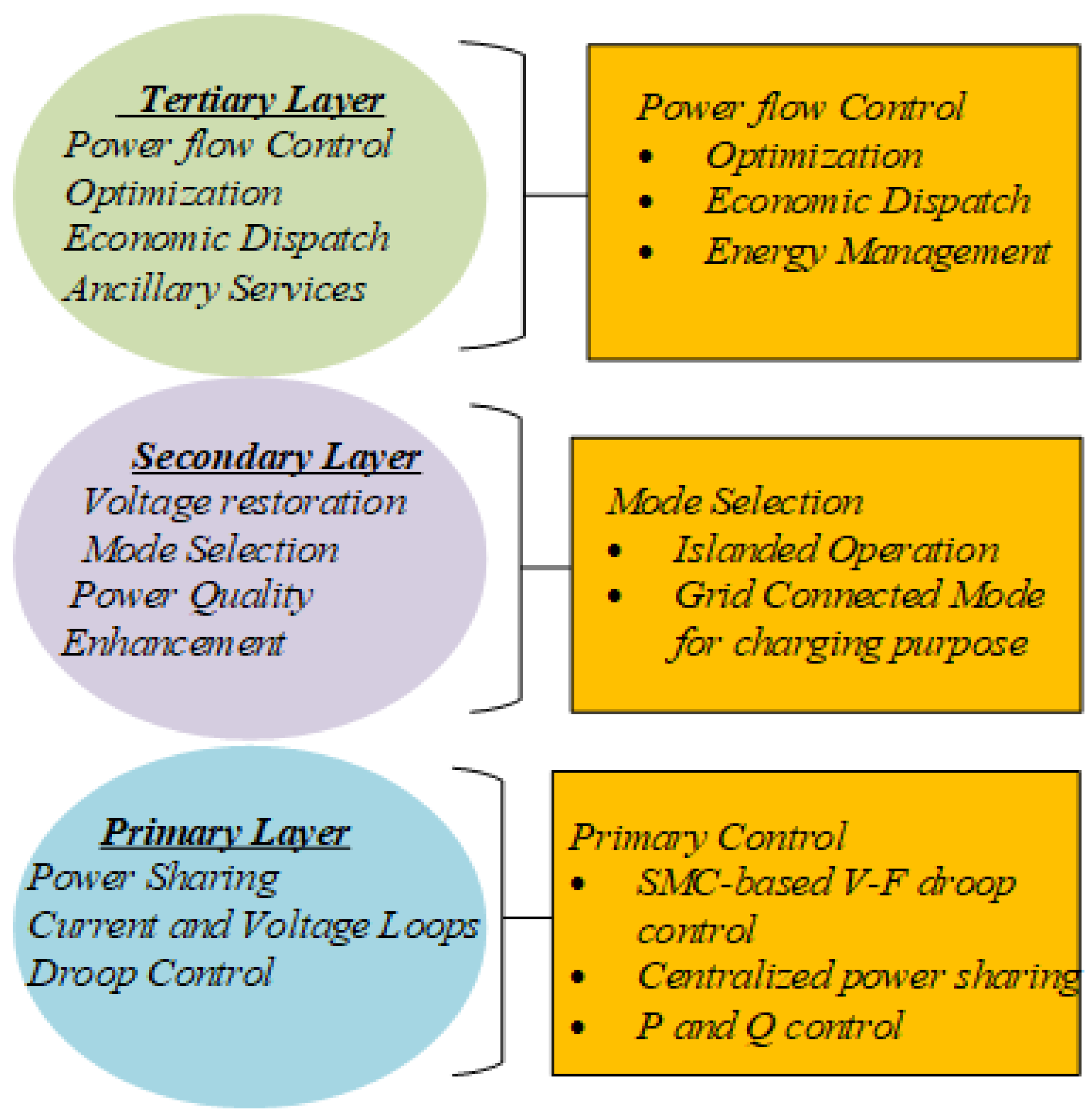
All DGs operate on a common electrical bus and are treated symmetrically at the primary control level. Each DG or converter is equipped with a local droop controller, which allows it to autonomously respond to changes in local frequency and voltage without the need for communication. This is the primary layer of the hierarchical control and enables decentralized, plug-and-play operation across multiple DGs, facilitating fair power-sharing based on their respective droop characteristics.
The second layer of the control hierarchy, known as secondary control, introduces global coordination. It monitors the system-wide variables, such as the average bus voltage or frequency deviations, and sends correction signals back to the primary controllers of the individual DGs. This layer acts as a supervisory mechanism, ensuring that system-wide objectives like voltage restoration, frequency synchronization, and coordinated load balancing are achieved. Importantly, while the secondary controller exerts global oversight, it does not impose a master-slave configuration on the DGs. Instead, it influences all units uniformly via reference adjustments, preserving their local autonomy.
In recent years, hierarchical or layered control strategies have become essential in managing the growing complexity of sustainable energy systems across various domains, including shipboard microgrids, offshore drilling platforms, and unconventional hydrocarbon extraction systems. These control frameworks are designed to manage the multi-scale dynamics, nonlinear operating conditions, and distributed energy resources (DER) integration challenges that arise in both maritime and oil field applications. Hierarchical control structures typically consist of primary, secondary, and sometimes tertiary levels, each responsible for handling real-time stability, coordination, and system-level optimization under dynamic disturbances [
6].
The relevance of such control paradigms is not restricted to the marine environment. In hydrocarbon reservoir engineering, for instance, energy input control and environmental adaptability are equally critical. Studies such as the author in [
7] demonstrate how sediment and particle behavior, specifically the use of kaolinite as a fracture proppant in CO
2 fracturing fluids, demands tightly regulated control over fluid dynamics and energy delivery to maintain system integrity and operational efficiency under changing pressures and chemical conditions [
8]. Similarly, paper [
9] investigate sediment instability in hydrate-bearing strata in the South China Sea, where dynamic energy input from horizontal well-bore gas production causes transient disturbances that require responsive, hierarchical management mechanisms to mitigate failure risk.
By combining AC and DC power grids, a microgrid can distribute power. Stable voltage and frequency are the primary functions of the microgrid’s control design. In conventional power systems, the current-controller-based proportional control designs were used to operate locally for every distributed interlinking converter, even though centralized control architectures are typically employed for primary controllers [
10]. This decentralized droop controller provides smooth power flow and stability to the system. However, voltages and frequency variations due to grid transitions or dynamic load variations can cause system abnormalities. Therefore, a robust control strategy is required to overcome this issue [
11].
For instance, paper [
12] shows that a distributed secondary control can maintain voltage and frequency stability in the event of communication failures or node outages, while centralized systems are more vulnerable to single points of failure. Similarly, paper [
13] emphasizes the modularity and plug-and-play capabilities of distributed control, which enhance the scalability of microgrid networks. These references provide concrete evidence to support our claim and make the discussion more rigorous.
Recent advances in robust control for microgrid applications have explored several techniques, including
control for disturbance rejection and stability enhancement, phase lock loop (PLL)-based methods for frequency synchronization, and low-frequency oscillation damping in converter-dominated systems [
14]. While these approaches have shown promising results in improving grid-connected microgrid performance and addressing specific instability issues, they often involve complex mathematical formulations and high computational burden, making them less suitable for real-time embedded implementation in shipboard systems [
15].
In contrast, the control strategy proposed in this study adopts a hierarchical structure, combining a conventional PI-based droop controller at the primary level with a computationally Sliding Mode Controller (SMC) approach at the secondary level. This design aims to ensure a robust dynamic performance, reduced voltage/frequency deviations, and resilience against parameter uncertainties, while remaining suitable for real-time execution on embedded hardware platforms. By focusing on PI–SMC integration, the proposed method offers a practical yet effective alternative to high-complexity robust controllers in the context of hybrid shipboard AC/DC microgrids [
16].
The Interlinking Converter (IC) uses frequency-voltage droop control that incorporates the secondary AC control effect. Hence, the ICs are critical components in SMG as they facilitate controlled and stable energy transmission and the transformation between the alternating current (AC) and direct current (DC) sides [
17,
18]. A robust control scheme for the hybrid AC/DC SMG is designed and implemented, and provides a competitive analysis in this research to enhance the multiple innovative hybrid AC/DC microgrid control configurations. On IC, a hierarchical primary and secondary controller is used to connect the AC Microgrid and DC microgrid to alleviate non-linearities during power fluctuations. The IC secondary controller has proportional integral (PI) controllers and an SMC.
The proposed robust hierarchical control strategy is not formulated as a classical multi-objective optimization problem using tools such as Pareto front analysis, model predictive control, or evolutionary algorithms; it inherently addresses multiple control objectives simultaneously through its layered architecture. The control framework integrates a primary control level based on droop and current regulation, which ensures local voltage/frequency stabilization and proportional power-sharing among distributed generators during nominal operation. Although no explicit optimization solver is used, controller parameters such as droop coefficients, sliding surface gains, and boundary layer thresholds are tuned through iterative simulation-based sensitivity analysis to achieve a balanced performance across all the key control objectives. Therefore, the proposed control strategy functions as an implicit multi-objective controller, capable of satisfying diverse and often conflicting demands in hybrid shipboard microgrids.
This study proposes a robust hierarchical control framework that integrates a classical PI control with a nonlinear SMC to enhance the dynamic performance and operational resilience of hybrid AC/DC shipboard microgrids. Unlike existing works that treat AC and DC domains in isolation or apply only linear control methods, the novelty of this approach lies in its dual-layer structure: the PI-based primary layer enables decentralized voltage and frequency regulation and supports droop-based power sharing among distributed generators, while the SMC-based secondary layer acts as a supervisory controller to reject disturbances and maintain reference tracking during system transients.
This hybrid design enables the system to handle power fluctuations, load switching, and line impedance variations without relying on complex centralized coordination. The controller’s stability is guaranteed through the Lyapunov analysis. The proposed hierarchical control strategy supports sustainable operation by improving voltage and frequency regulation under dynamic conditions, as demonstrated through both MATLAB/Simulink simulations and real-time hardware validation on the NVIDIA Jetson Nano platform.
The rest of the paper has been reorganized as follows: In
Section 2, the problem formulation is conducted, and it is where we discuss the modeling and design of the hybrid AC/DC SMG. In
Section 3, the proposed hierarchical control scheme of the SMG system is explained.
Section 4 provides the simulation results.
Section 5 discusses the practical hardware implementation.
Section 6 gives a conclusion and future directions.
2. Modeling of Hybrid AC/DC Microgrid System
The AC microgrid consists of a large number of distribution generators, which can be diesel/gen or renewable, delivering into AC loads, including the traditional shipboard utilities and AC propulsion systems. These components run on a synchronized AC bus where voltage and frequency are regulated, with conventional droop control or central frequency regulation strategies.
The Bidirectional Interlinking Converter is at the heart of this system and plays a crucial role in that it makes it possible for the AC and DC networks to transfer energy bidirectionally. It guarantees power balance, voltage stabilization, and smooth operation during grid-connected and islanded modes. From a technical point of view, the implementation uses power electronic devices controlled by control algorithms that determine the switching signals according to load conditions, grid status, and the availability of energy. In general, the model is an advanced microgrid configuration that supports convenient operation of both DC and AC loads and sources, utilizes the available renewable energy to the fullest extent possible, and increases the system robustness through smart energy management and the proper control of bidirectional power flow.
To ensure compliance with industry-accepted practices, the proposed control architecture and microgrid model have been designed in alignment with key international standards. In particular, the interconnection and control interfaces are guided by IEEE 1547-2018, which specifies the requirements for the interoperability and performance of DER connected to electric power systems, including voltage and frequency regulation, fault ride-through, and reactive power support [
19].
For maritime-specific applications, system layout and protection schemes adhere to the IEC 60092-101 standard, which outlines the definitions and general requirements for electrical installations in ships, including insulation levels, earthing methods, and voltage limits [
20]. The adherence to these standards ensures that the proposed hybrid AC/DC shipboard microgrid design not only meets control performance criteria but also satisfies safety, interoperability, and power quality requirements expected in practical marine deployments.
2.1. Construction of the Shipboard Microgrid Mode
The development of the single-line diagram shown in
Figure 1 is illustrated in the practical and theoretical requirements of next-generation shipboard power systems, particularly those transitioning toward hybrid AC/DC architectures. This transition is motivated by the need to increase energy efficiency, system reliability, and environmental sustainability onboard vessels that operate under varying electrical demands and constrained physical space. The proposed model adheres to the principles established in the maritime electrical architecture standards [
21], which support the hybridization of AC and DC domains to accommodate diversified loads and DERs. The structure supports a future extension toward decentralized or hierarchical control, aligning with the trends in smart maritime electrification [
22].
2.2. Components and Control Considerations
Figure 1 incorporates the key elements commonly found in advanced shipboard microgrids. These include distribution generator (DG), which are modeled as diesel-based synchronous generators or renewable-fed converters, each equipped with droop-based primary controllers to enable autonomous operation and load sharing. The AC load section, represented using
,
,
models essential shipboard systems like propulsion, Heating, Ventilation, and Air Conditioning (HVAC), and lighting. The DC subsystem, powered by PV arrays and buffered by a BESS, supplies the navigation electronics, communication systems, and charging interfaces. The BESS plays a critical role in smoothing power fluctuations and supporting State of Charge (SoC) balancing, as recommended in [
23].
The IC is implemented as a bidirectional voltage source converter (VSC), which ensures a dynamic energy exchange between the AC and DC subsystems. Its control system is central to the microgrid’s reliability and is composed of a hierarchical architecture combining PI control in the primary layer with SMC in the secondary layer. The IC controller is responsible for maintaining voltage and frequency stability during power mode transitions, disturbances, or partial faults. The transmission lines connecting these components are modeled with lumped resistance and inductance (
,
) to capture real-world distribution behavior and transient interactions [
24].
2.3. Sustainable Operation and Control Mechanism
To achieve sustainable operation, a Robust Hierarchical Control Strategy is proposed and validated in this study. The primary control layer uses local droop control and current regulators to manage decentralized power-sharing and stabilize voltage/frequency at the converter outputs. The secondary control layer, based on SMC, compensates for residual deviations by generating reference correction signals, which dynamically adjust the control targets under disturbances such as mode switching, harmonic injection, or nonlinear load variations [
25].
A Lyapunov-based formulation ensures the stability of the sliding surface
s, with the convergence conditions
, providing robustness even in the presence of parameter uncertainties. The system’s chattering is mitigated using a boundary layer approach, as
, where
serves to smooth control actions for real-time feasibility. This layered strategy avoids the reliance on communication-heavy centralized controllers and ensures a modular, scalable, and fault-tolerant operation [
26,
27,
28].
2.4. AC Microgrid Modeling
To design a hybrid microgrid where AC loads
and
are connected. The electric current of type DGs powers the load. We may use Kirchhoff’s Voltage Law (KVL) on the AC source side to obtain the equations. The list of parameters used in the equation derivations are provided in the
Appendix A Table A1. The research will demonstrate a hierarchical control structure for DG modules that consists of two levels. The first level includes main controls that are based on droop, and the second level includes secondary controls that are used to restore voltage and frequency characteristics [
29,
30]. It is possible to obtain the AC source side equation from
Figure 1, which can be given as
where the voltage across the line impedance is the rate of change in the line inductance.
so, (
1) can be written as
where time-derivative expression with standard state-space vector notation representation of the three-phase system can be given as
By rearranging (
3), we obtain
Now, the AC load side equation is the summation of the voltages across the load impedance.
where
so, (
5) can be written as
By rearranging (
7), we obtain
The
state space model for (
4) and (
8) of AC network can be given as
2.5. DC Microgrid Modeling
On the DC microgrid, a KVL is used to solve the DC source side mathematical equations. Connecting a DC source to a BESS that maintains a constant voltage is an example of a DC source. Moreover, a DC load never changes its power consumption. The DC source voltage is equal to the total of the load voltage and the voltage along the losses in the transmission line, as stated by KVL at the DC Microgrid (MG).
With a constant power demand,
stays the same, which can be given as
Reducing the number of DG units needed is achieved by the use of RES to provide electric ship power. On the other hand, the efficiency of transmitting electricity to the consumption power system grows dramatically due to their inherent characteristics; most RES are equipped with BESS as the year progresses. A smooth and more dependable power-producing unit is achieved by using storage devices, such as batteries and fuel cells.
3. Proposed Robust Hierarchical Control Structure for Microgrid
The steady-state condition is directly affected by the short-term operation of primary and secondary controls. In order to obtain reliable steady-state analysis in AC/DC microgrid modeling, it is necessary to have both the main and secondary controllers active. Hybrid SMG systems cannot operate without a reliable and appropriate method of power management, which allows for the regulation of load allocation among DC and AC power sources. Fewer attempts have been made in power management between AC and DC power generations for hybrid systems until now, while controlling power distribution in AC and DC microgrids. A reliable power-sharing method has been used to execute power-sharing control in microgrids. Multiple converters must work together to find the reference power that corresponds to the frequency droop characteristics [
31,
32].
All the control modules are included in load balancing using the drooping slope technique.
Figure 2 shows the flow of the hybrid SMG hierarchical control design. Centralized and decentralized controllers have been developed using a number of control algorithms, including
, Linear Quadratic Regulator (LQR), sliding mode, model predictive control, and artificial intelligence techniques, including fuzzy logic, neural networks, and genetic programming.
Secondary control is the next logical step after this degree of control. The load variations in the local voltage and global frequency are what secondary control is aiming to eradicate. There has been much research on centralized control systems in high-voltage transmission and distribution networks. Additional goals such as harmonic correction, reactive power-sharing, and voltage imbalance have been included in the secondary control [
33]. The third level of control determines the worldwide economic dispatch across the network based on current energy prices and market circumstances.
The earlier works on control problem formulation considered only primary droop controls. However, higher control levels must be implemented in practical systems for the microgrid to function optimally and safely by using hierarchical control schemes. By including the comprehensive hierarchical control models, the solution obtained by applying the primary droop-controlled method in a controlled AC microgrid was determined to be the correct one in contrast to the solution gained by using a hierarchical power flow model [
34].
Technological advancements have facilitated the proliferation of microgrids in energy generation, control, computer hardware, and software utilization for microgrids. The advancement of MGs has been driven by industrial collaborations seeking to cut costs and boost their dependability and resiliency. Consequently, MGs is the dominant power source for many commercial and residential applications at present.
3.1. Modeling of Voltage Source Converter (VSC)
Figure 3 shows the three-phase VSC design for hybrid marine MG. The hierarchical control structure is managed by a two-level VSC device [
35]. A voltage regulation controller is a key component of the main controller. Another option is to use the (
) to regulate the primary control layer.
is the amount of current flowing across the filter capacitor, and
is the current flowing through the other branches of the VSC. The inverter output voltage may be given using
So, the inverter output voltage is equal to the inverter’s instantaneous voltage plus the line inductance and resistance. We implemented a three-phase voltage system as an IC for a hybrid microgrid system. The three-phase root mean square (RMS) voltage is obtained straight from the AC bus or a three-phase transformer, without the need for any double-voltage capacitor [
36,
37,
38,
39,
40]. In the aftermath of transits, the RMS voltage remains steady and stable throughout. Placing an LC filter network between the load and the AC bus becomes necessary. However, this study does not include a filter design. As a result, we treated them as constants in statements.
Applying the
-transformation of three-phase currents.
and
The state space model of (
17) and (
18) can be represented as
3.2. Proposed Robust Controller Design and Analysis
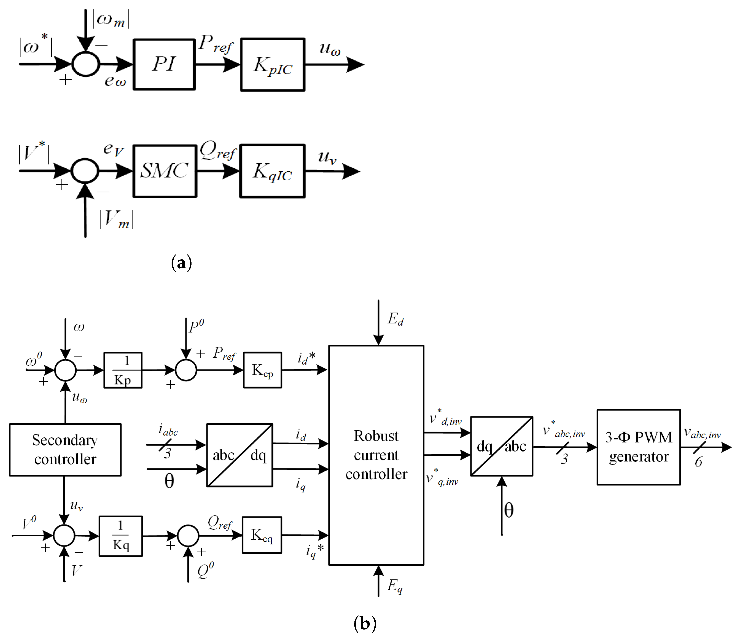
The proposed robust architecture for the secondary controller is shown in
Figure 4a. In this case, the primary controller design relied on a reliable SMC as a reference signal. With the primary controller’s responsibility to reduce voltage and frequency droops, the secondary controller will provide its support to the primary controllers, as shown in
Figure 4b, so that the power grids may contain even more robust synchronizations. In addition, the secondary controller guarantees that the load is constantly receiving the necessary amount of demand power. Under extreme conditions in either the AC or DC loads, a standard control signal is provided by the secondary controller, which also keeps an eye on the voltage and frequency fluctuations in the hybrid grid. The hierarchical control structures
and
are produced by processing the control signals
and
with converter gains
and
, respectively. Whereas,
= 1/
= 1/
.
Figure 4b displays the traditional current controller system. The IC’s voltage and frequency are controlled by the primary control design, which is based on droop control. The suggested robust secondary controller supplies the primary controller with reference signals
and
in order to implement the hierarchical control design. The droop controller will generate
gating pulses by monitoring the grid voltage and frequency. The voltages are
and
. A three-phase
inverter signal for the Pulse Width Modulation (PWM) generator is generated by processing the park inverse transformation using the
inverter signals that are produced by the robust current controller. The suggested rule for secondary control may be expressed as
If
, then the control signal is
, the controller gain is
, and the sliding surface is
s. Therefore, the applicable control regulations in this instance might be depicted as
and
The computational gains used in the controller are shown in
Table 1. Errors between the output and the reference can be given as
At the AC load, equations can be given as
and
are located. The reference currents are
and
. There will be a sliding surface
s.
Sliding surface
s derivative is
at a constant reference value
referring (
27)
From (
18)
Rearranging the terms,
the simplified form can be given as
where
Here, represents the aggregated dynamic influence of voltage deviation and system rotation, while reflects the net damping factor influenced by line resistance and sliding surface gain. These clarifications help link the mathematical formulation to its physical significance in microgrid control dynamics. To enhance inter-predictability and engineering insight, we provide the physical significance of the intermediate variables introduced in the sliding mode control derivation. The term represents a composite dynamic quantity that captures the aggregated effect of system-level variables such as voltage deviation, frequency error, and their rate of change, particularly influenced by the angular frequency of the AC reference frame.
Similarly, the parameter
, introduced in the sliding surface definition and control law, reflects the net damping effect applied through the control surface. It is influenced by the line resistance
R, the inductive reactance term
L,
, and the sliding surface gain 0. From a control perspective,
determines the rate of convergence toward the sliding manifold and defines the slope of the Lyapunov energy function derivative
. Larger values of
correspond to faster system convergence and stronger robustness to disturbances, but may introduce more aggressive switching or chattering if not properly bounded by the boundary layer parameter
. The condition for
to satisfy is
Here
is a constant that is positive. While the Lyapunov-based SMC formulation guarantees system stability through the condition given in Equation (35), the selection of key parameters, including the sliding gain
and the lower-bound damping threshold
, is a critical step that directly affects the robustness, convergence rate, and practical implementation of the controller. In this study, these values were not assigned arbitrarily but were obtained through a structured sensitivity analysis using MATLAB/Simulink. Multiple simulation scenarios involving step changes in load, varying line impedance, and AC/DC transition disturbances were evaluated to tune these parameters such that the system maintained fast convergence, low steady-state error, and minimal chattering.
This empirical tuning process is a widely accepted practice in SMC applications for real-time embedded control, where the analytical solutions for gain selection may be difficult to generalize due to system non-linearities and hardware constraints. In particular, embedded controllers like the NVIDIA Jetson Nano impose limitations on the switching frequency and computational overhead, necessitating a trade-off between theoretical optimality and practical feasibility [
41]. Therefore,
and
were selected not just for theoretical stability, but also to ensure smooth actuator behavior, chattering mitigation, and a robust dynamic response under uncertain operating conditions [
42].
Next, we will choose a suitable Lyapunov function
for the stability assessment of our designed control
Then
From (
32)
Chattering can be reduced by choosing
s as,
where
is a very small positive value. To mitigate the well-known issue of high-frequency switching (chattering) inherent in classical sliding mode control, a boundary layer approach is adopted around the sliding surface. In Equation (39), the discontinuous sign function
is replaced with a saturation function, introducing a boundary layer of thickness
. This smooth approximation effectively limits the amplitude of the control signal near the sliding manifold, thereby reducing switching noise and actuator wear in practical hardware implementations [
43]. In this work, a value of
was selected based on extensive simulation-based tuning to achieve a compromise between tracking performance and chattering suppression. Smaller values of
offer faster convergence but may reintroduce chattering, while excessively large values compromise the control accuracy. The chosen value was found to provide sufficiently smooth control action while preserving dynamic responsiveness, particularly when deployed in the real-time embedded environment of the NVIDIA Jetson Nano. The closed-loop control law equation will be
Substituting (
40) into (
38), we obtain
or
where
Since
is a positive constant, we have
Now, by substituting values of in (
44) into (
43), we obtain
Equation (
46) guarantees that the suggested controller will be a strong stabilizing controller satisfying the requirements in (
44).
4. Simulation Results
The Matlab/Simulink tool has been used for the microgrid implementation and testing of our proposed controller. For the simulation platform, we developed the AC and DC power generation units and loads of microgrid systems. On the AC MG side, we used three identical DGs with a power rating and 400 volts three-phase RMS voltage. The DGs are connected to a bus with their local AC loads. Three distinct kW active loads with kVar inductive load in parallel are used with the circuit breaker combining the transmission line lumped impedances. The AC microgrid follows the Hz operating frequency. In addition, power can be sent to either side of the grid as needed by the load due to the IC, which is a 2-level VSC.
The PI controller is used within the primary control layer for nominal operating conditions, SMC forms part of the secondary control layer and becomes dominant during dynamic events such as load transients, mode switching, or disturbances where robustness against uncertainties is critical. This clarification improves the consistency and interpretability of the control hierarchy.
PV and BESS are examples of DC sources, whereas DC resistive loads and transmission lines with resistance make up a DC microgrid. The DC bus voltage is 500 volts. Three identical resistive loads are connected to it through a circuit breaker. The DC load we use is
W each. The hierarchical controller uses AC and DC line current feedback to produce commands for the primary controller, which renders the IC. The simulation parameters are given in
Table 2.
4.1. Case 1: Power Flow from AC Microgrid to DC Microgrid When DC Sources Are Not Enough and Vice Versa
The power flow analysis of the hybrid SMG has been simulated using MATLAB/Simulink to compare the performance of the conventional PI and the proposed robust secondary control schemes. At simulation time s, we took into account the transition from the AC grid to the DC grid.
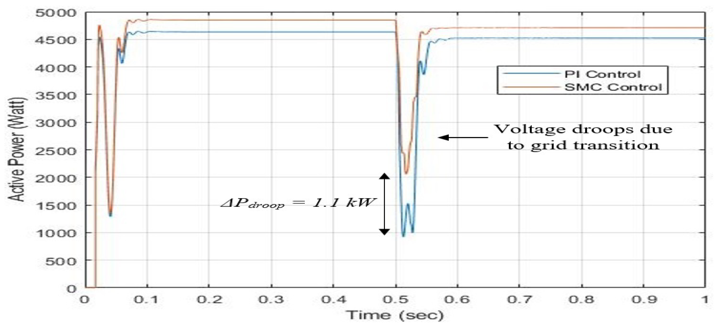
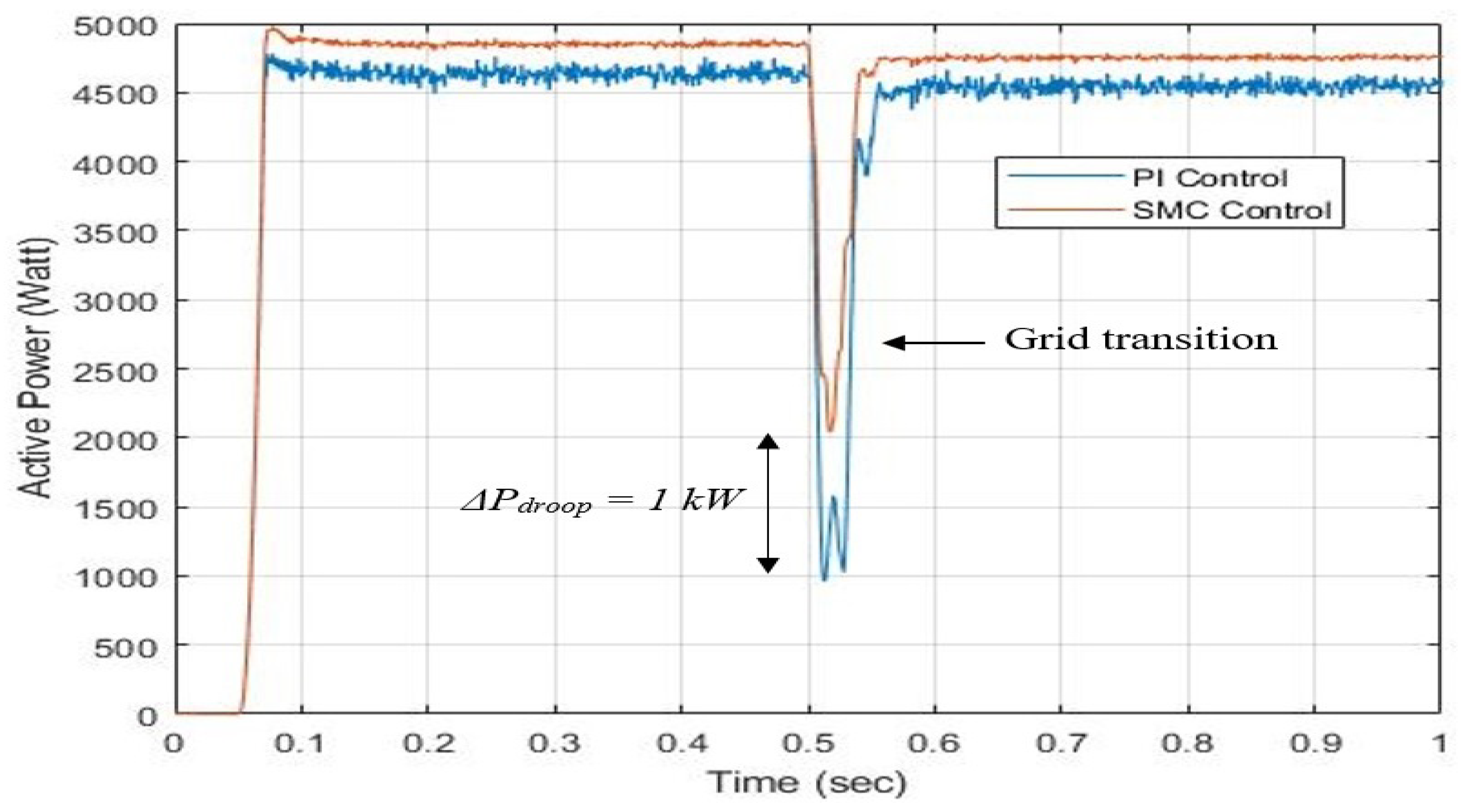
The variations in the AC active load power in the hybrid SMG are shown in
Figure 5. The blue line represents the secondary controller reaction based on PI, whereas the orange line represents the response based on SMC. Initially, the IC will function as a rectifier and meet the AC and DC load power requirements while the grid is run by an AC microgrid. Utilizing a conventional PI controller regulates the load power to
kW for the duration
s, while the proposed SMC-based secondary control achieves a better response, regulated to
kW.
W is the result of comparing the load power. After that, because the AC sources are disconnected, the power is supplied to the DC and AC loads by the PV between
s. Here, we can analytically observe that during this inverter mode, the PI-based controller has an AC load power deviation that remains the same compared with the SMC-based controller. Furthermore, we notice a significant voltage drop improvement by employing a secondary controller strategy. The maximum voltage drop using the PI controller is
kW greater than the SMC-based controller, which is
kW. Hence,
kW.
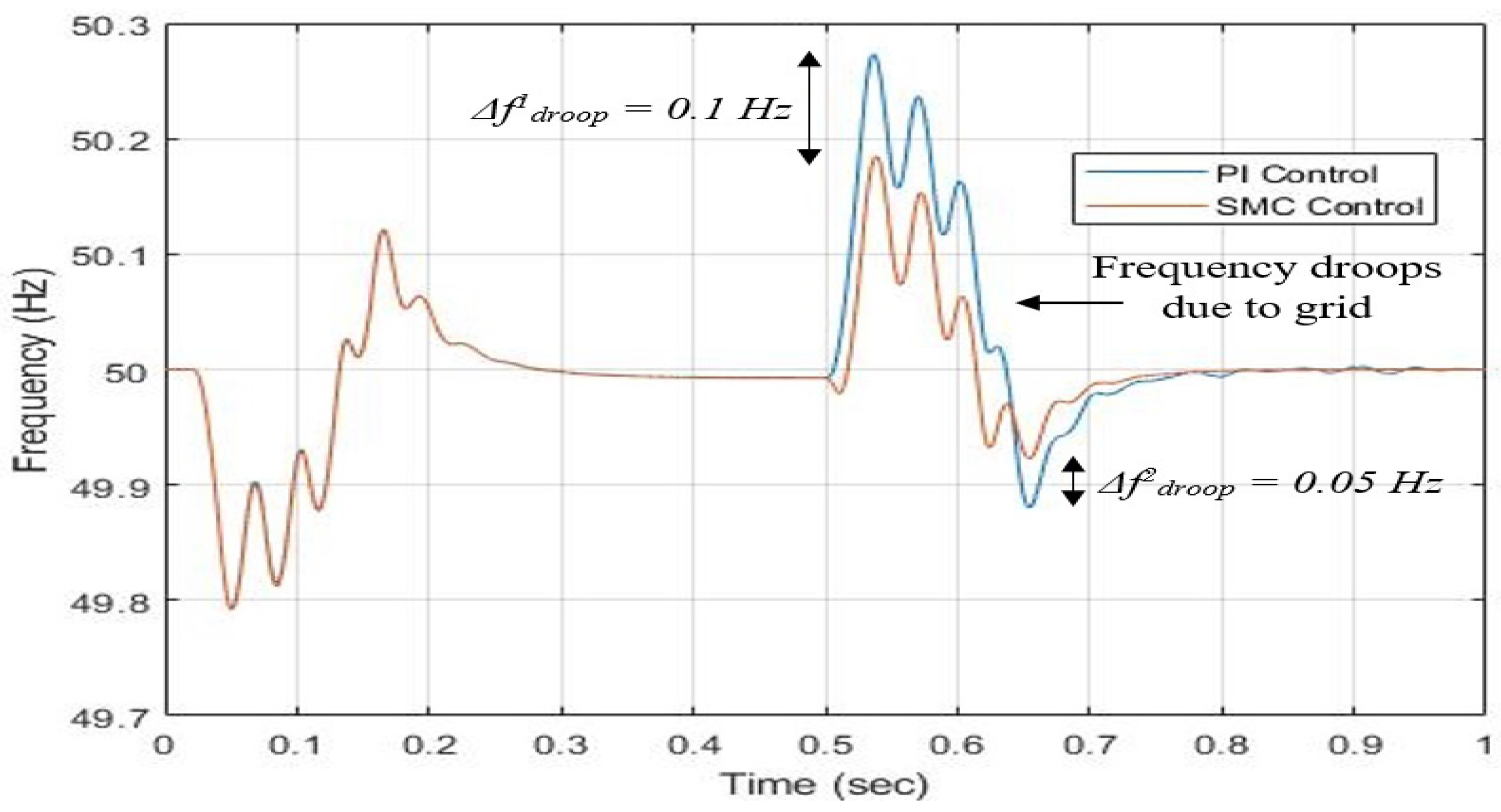
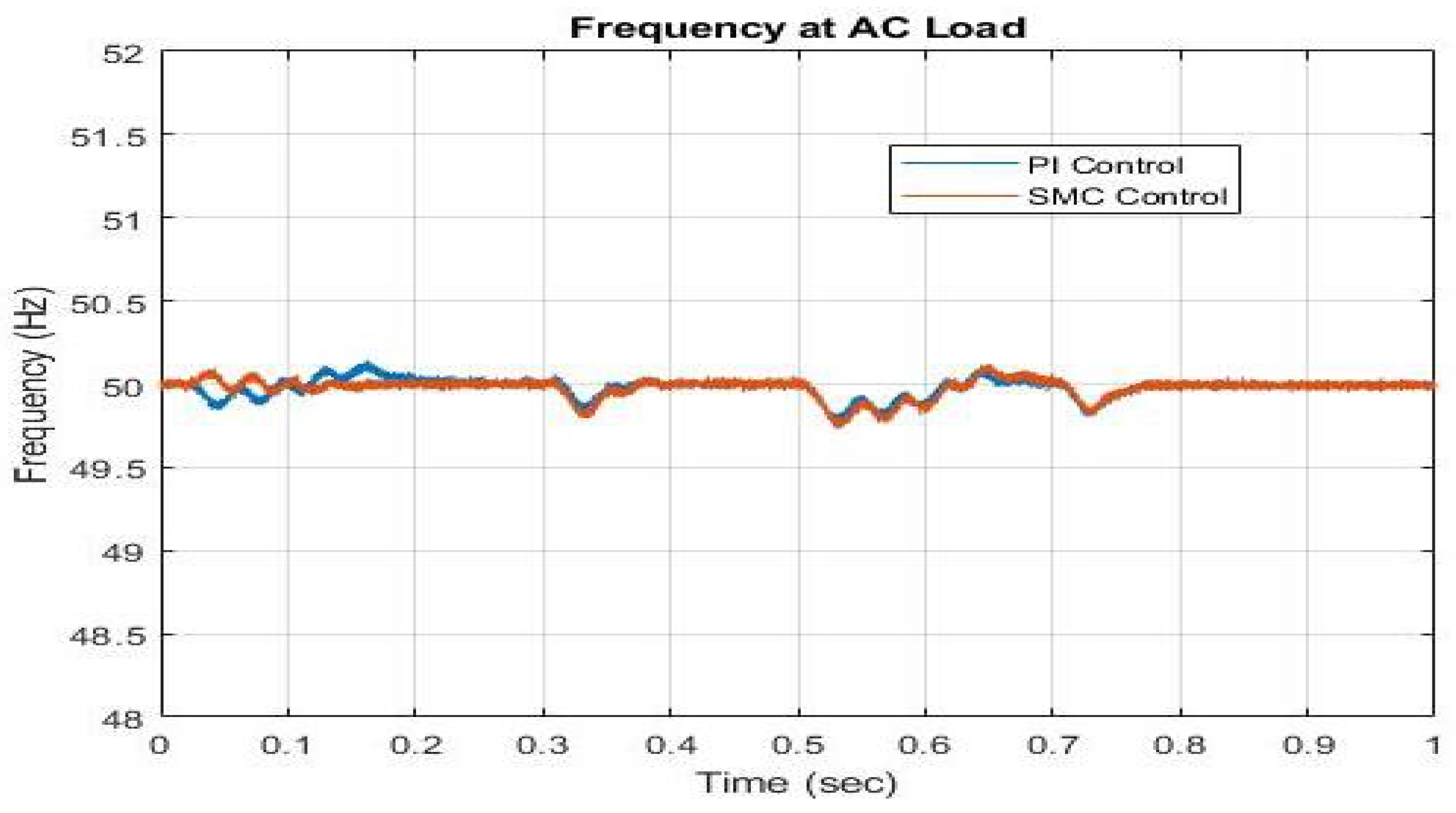
During the AC to DC grid transition at s, the PI controller exhibited a peak frequency deviation of 0.33 Hz, whereas the proposed SMC controller maintained deviation within 0.2 Hz, corresponding to an improvement of approximately 25.5%. Similarly, the power variations on the AC bus decreased from 4000 watts to 3000 watts under SMC, representing around a 20% reduction. These results validate the superior dynamic performance of the hierarchical controller in stabilizing the microgrid under abrupt power fluctuations.
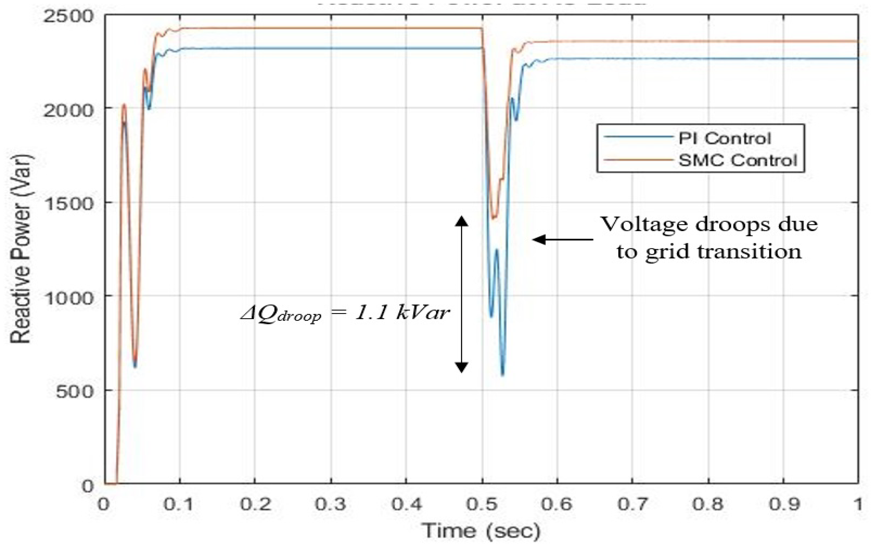
Figure 6 shows the reactive power waveform. Here we can see that from
s, the reactive power is
kVar and
kVar with SMC and PI-based controller, respectively. After the grid transition for testing purposes, the reactive power becomes
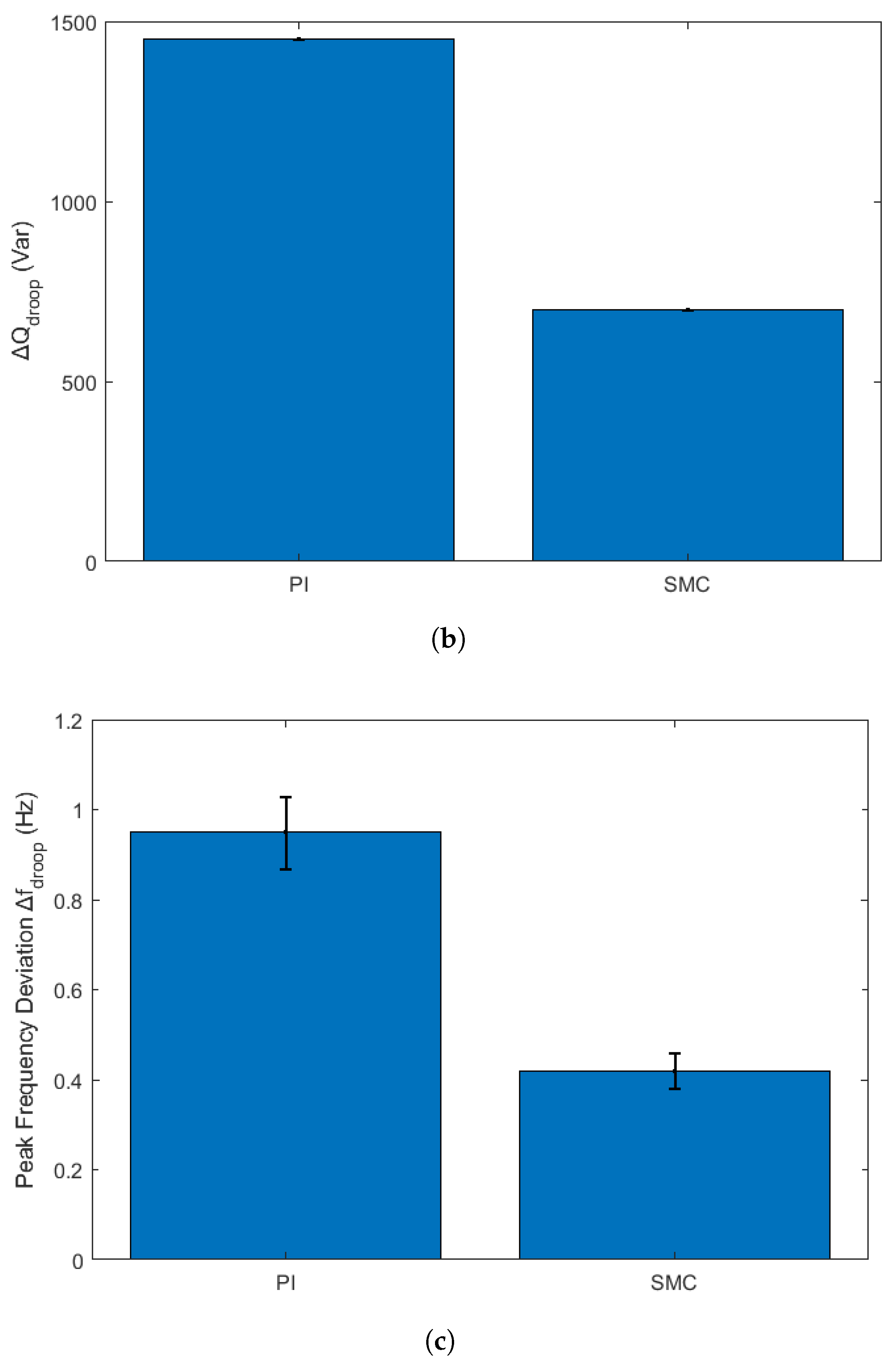
kVar and
kVar with SMC and PI-based controller, respectively. The reactive power droop due to grid transition for testing purposes in the case of SMC is
kVar and with PI
kVar. Hence,
Var.
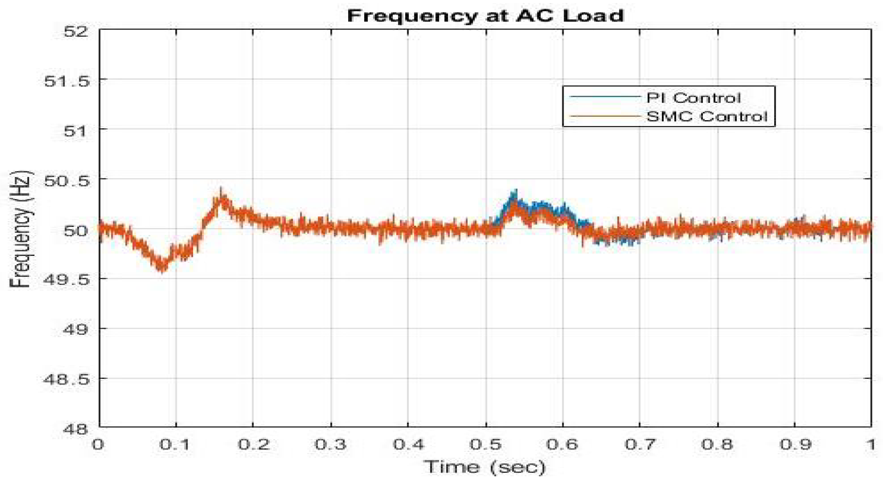
In
Figure 7, the frequency changes on the AC grid are shown. As opposed to traditional control, the results of controlling the frequency and steady-state performance from the controllers based on SMC are superior. The SMC-based controller is smoothly controlled at
Hz, in contrast to the PI-based controller, which exhibits frequency changes
Hz and
Hz, which shows better performance of our proposed control scheme.
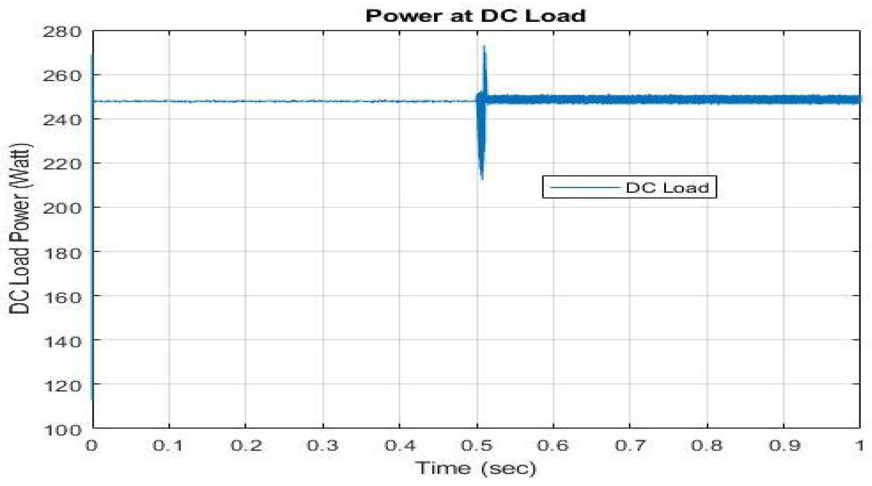
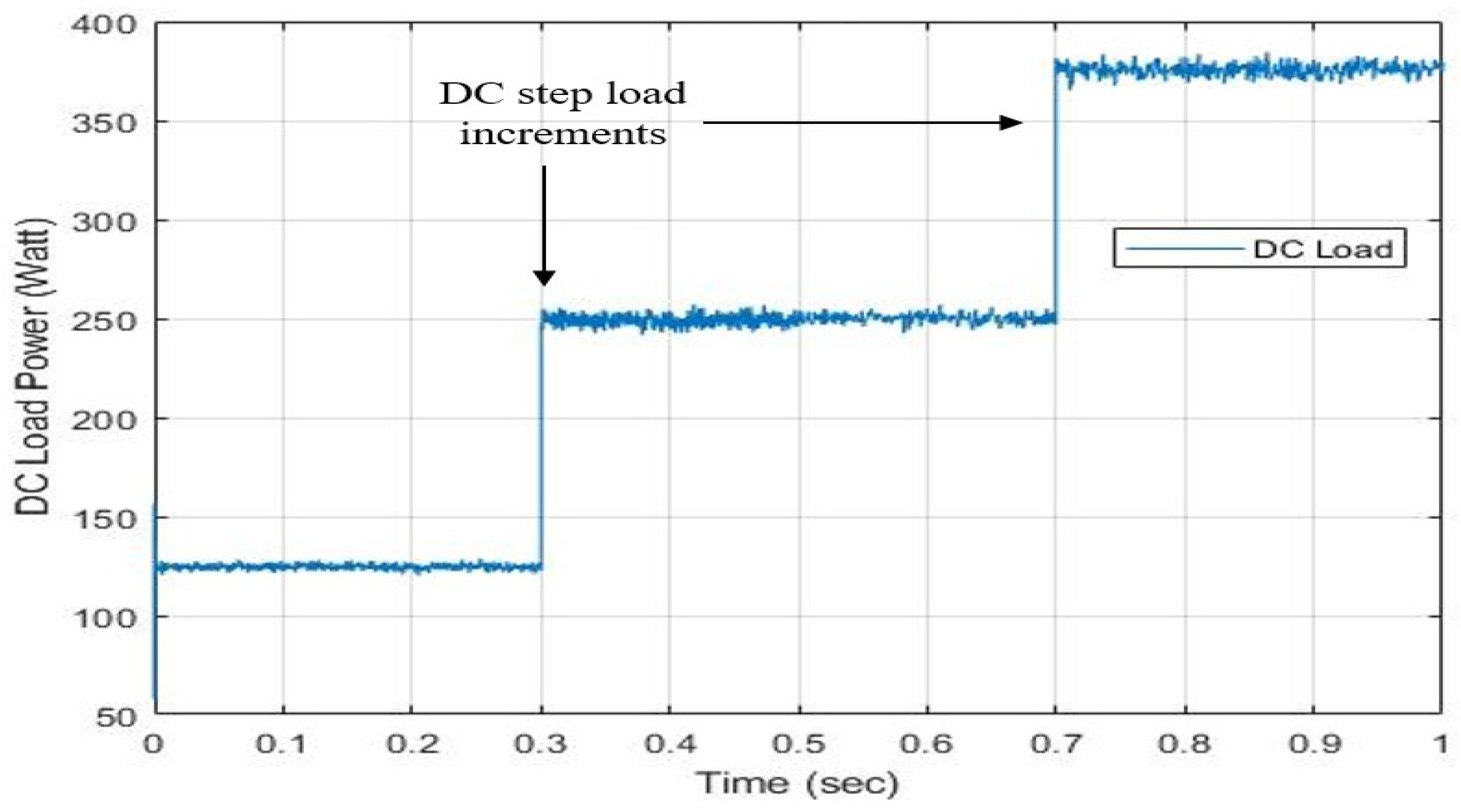
Figure 8 shows DC load waveform, which is initially regulated at
W, then there is an identical step load increment to
W. Here, DC load is obtaining power from AC source from
s. After that, it obtains power from the DC source. Once again, there is an identical load increment from
W to
W at
s. We also observed harmonics due to inverter switching in IC.
4.2. Case 2: Power Flow from DC Microgrid to AC Microgrid When AC Sources Are Not Enough and Vice Versa
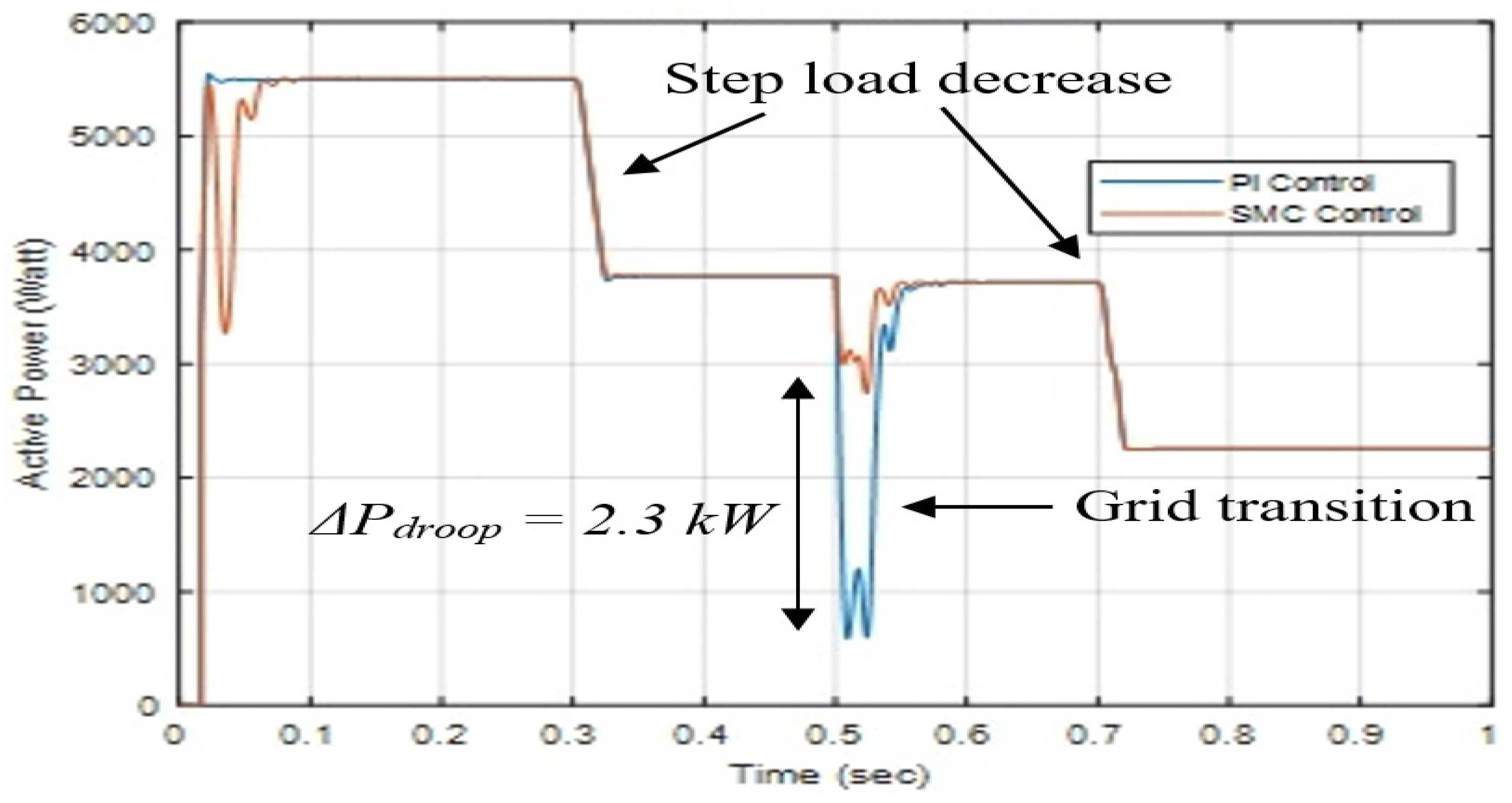
The fluctuation in the active load power caused by the microgrid changeover is shown in
Figure 9 compared with the traditional method and the robust secondary controller. The AC load power is initially limited to
kW since the grid is functioning from a DC source. Then at
s, the step load decreases to
kW, and at
s, the step load further decreases to
kW. A power droop due to voltage droops is seen after time
s when the grid changeover occurs. Using the traditional secondary controller method resulted in an active power droop of
kW. Nevertheless, the power decrease of
kW caused by the grid changeover is an improvement by SMC
kW.
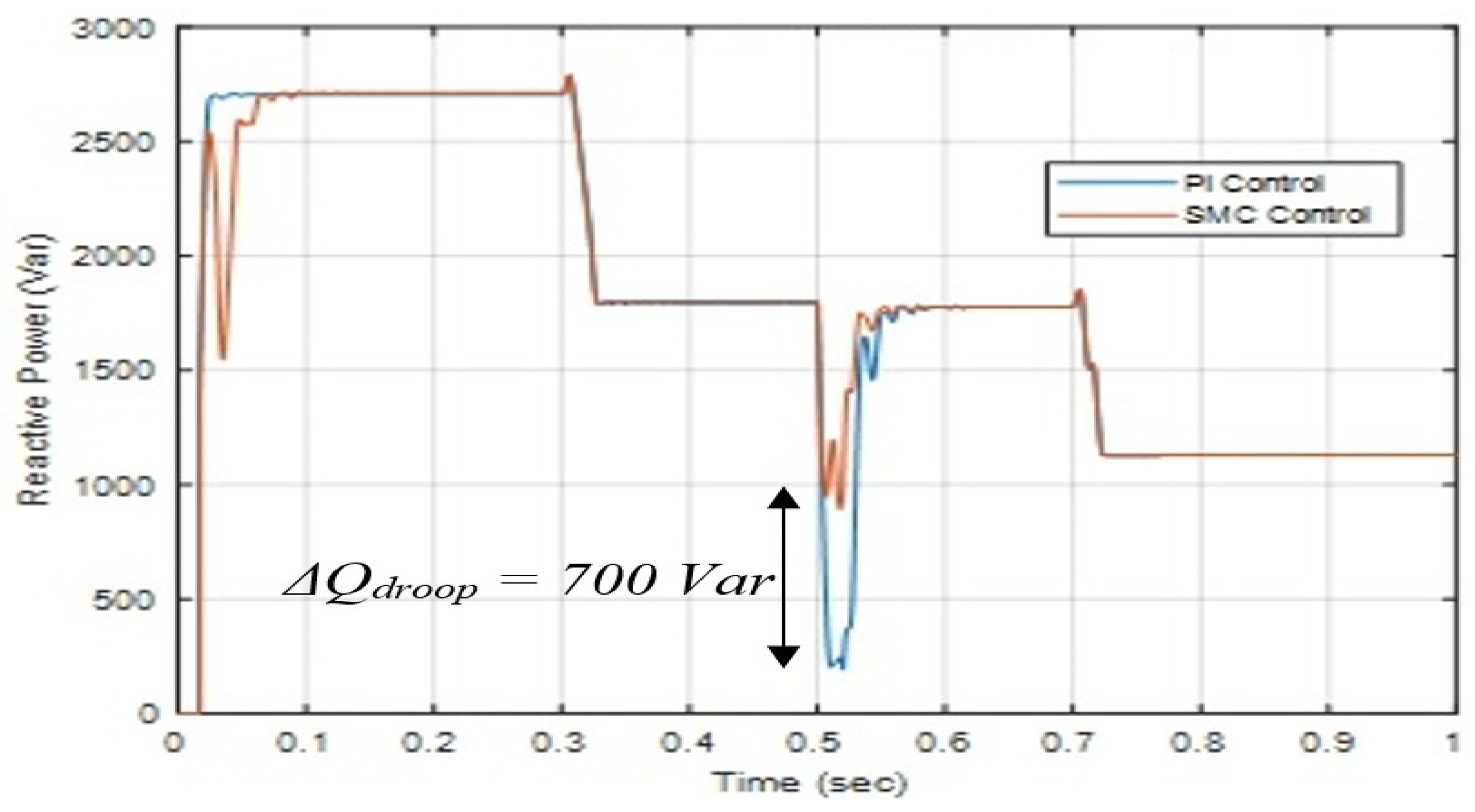
Figure 10 shows the reactive power waveform. Here we can see that the reactive power droop due to grid transition in case of SMC is
Var and with PI
kVar. Hence, we observe
Var.
The frequency differences caused by microgrid switching are compared in
Figure 11 between the traditional method and the proposed secondary controller-based method. At the beginning, the grid is running on a DC supply. Therefore, after time
s, it aims to stabilize and control its frequency at
Hz. We see frequency drops in both kinds of secondary controllers that are
Hz and
Hz, showing a better performance of our proposed control scheme. We observed that the SMC-based secondary controller approach leads to far better frequency droop steady-state responsiveness.
4.3. Results and Discussion
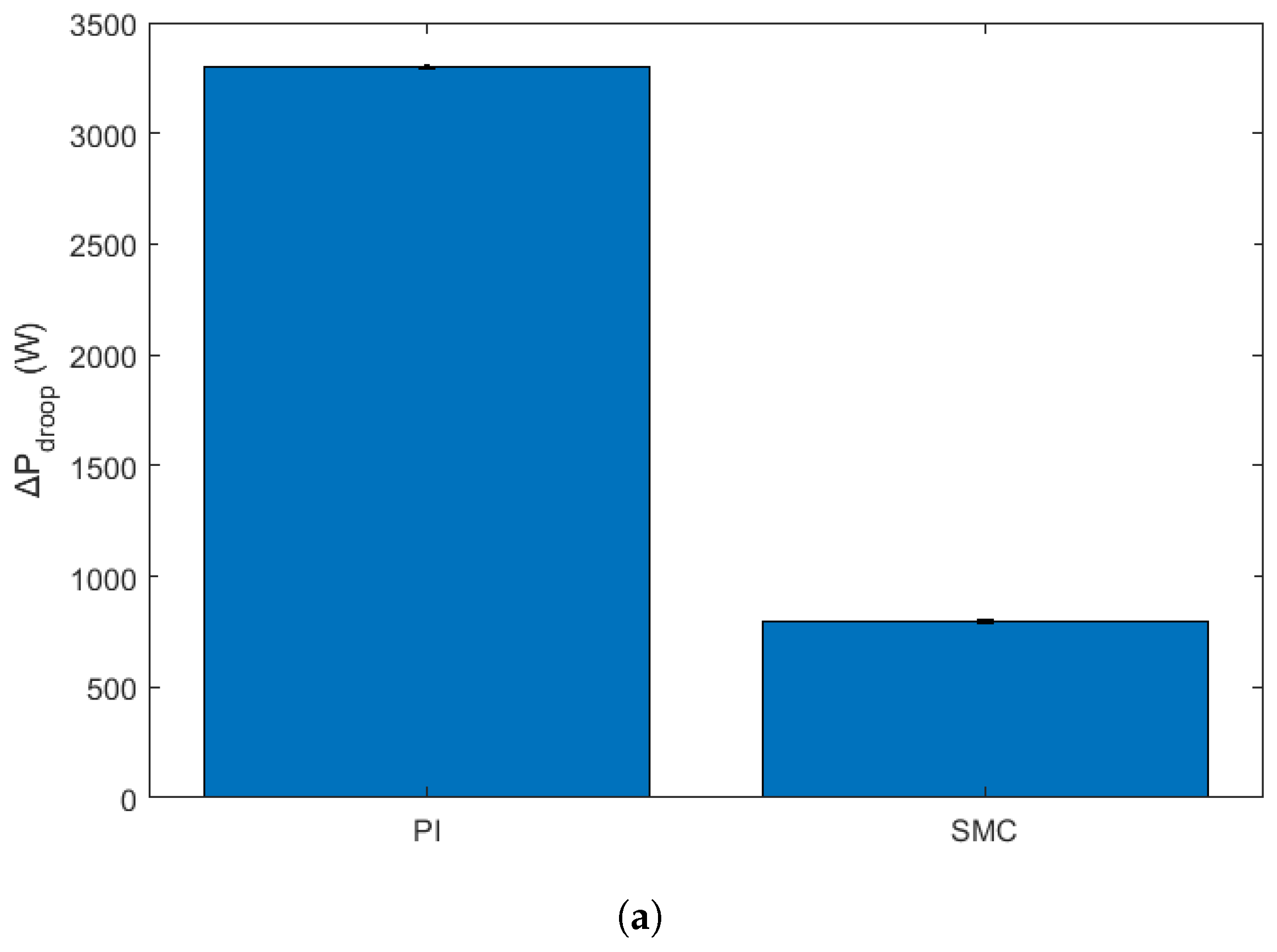
To strengthen the robustness and statistical validity of the simulation results, particularly those reported in
Figure 5,
Figure 6,
Figure 7,
Figure 8,
Figure 9,
Figure 10 and
Figure 11, we conducted multiple repetitions of each test case under slightly varied operating conditions. Specifically, each control scenario was simulated five times with randomized initial conditions, minor variations in line impedance, and 10% load perturbations to emulate a realistic operating variability. The reported values for
and
in the figures now represent mean values across these repetitions, and error bars have been added to indicate the standard deviation of each data point. This presentation highlights the consistency and resilience of the proposed SMC-based controller in reducing both active and reactive power droop under dynamic disturbances, thereby reinforcing its effectiveness and statistical reliability over conventional PI-based methods. The analytical error bars are shown in
Figure 12.


