1. Introduction
With the increasing global reliance on renewable energy, renewable energy technologies such as wind power generation occupy an increasingly important position in the energy mix. However, the intermittent and fluctuating nature of wind and photovoltaic resources is a challenge to the stable operation of power grids and energy efficiency [
1]. Franciele et al. [
2] aimed to integrate research, investment and policy making to make it possible for renewable energy systems to sustainably meet and exceed future energy demands. Selvam et al. [
3] proposed a new type of single-phase five-level transformerless photovoltaic inverter, providing a new direction for the large-scale application of distributed photovoltaic systems. Zhu et al. [
4] proposed a structural parameter optimization method for a hydrogen cooling system, achieving efficient heat dissipation while reducing the need for complex cooling equipment and lowering equipment investment costs. Badwawi et al. [
5] analyzed different methods and locations to understand and evaluate the complementarity between solar energy and wind energy systems. Younas et al. [
6] proposed a new strategy for hydrogen production and separation through micro-plasma and micro-bubble-mediated mass transfer, which has the advantages of low power consumption, reduced equipment size, and reduced principal cost. Zainal et al. [
7] comprehensively evaluated the major hydrogen production methods based on cost, environmental impact, and technological maturity. Among these, the efficiency, cost competitiveness, and scalability of green hydrogen production technology were confirmed to have been enhanced. Squadrito et al. [
8] analyzed and compared the unique advantages and disadvantages of various green hydrogen technologies, highlighting the advantages of electrolyzers in terms of distributed consumption and integration with the power grid.
Currently, although there are various ways to produce hydrogen, the most effective way to synergize with a grid connection and to consume renewable energy is still to produce hydrogen through water electrolysis in electrolysis tanks. Currently, the common electrolyzers are AWE [
9], PEM [
10], and high-temperature solid oxide electrolyzers (SOEC) [
11]. In order to investigate the coupling characteristics of hydrogen production from water electrolysis and renewable energy generation, Meng et al. [
12] constructed a simulation model for the wind–hydrogen coupling energy storage power generation system (WHPG), which not only reduced the power consumption of the electrolyzer but also increased the hydrogen production. Jiang et al. [
13] constructed an optimal size model for the wind–hydro coupling system (CWHS), calculated the fluctuation cost of wind power by using the “equal-kWh following load” method, and introduced chance-constrained programming to handle the uncertainties generated by wind power. Moreover, a thorough economic analysis and evaluation were conducted. Dai et al. [
14] proposed a predictive control strategy for a micro-scale wind–hydrogen coupling system. By applying the combined sigmoid function and the particle swarm algorithm to adaptively optimize the system parameters, the fluctuation in the power output of the wind–hydrogen integrated system was alleviated. However, the instability of renewable power generation still poses a formidable challenge to the efficient operation of electrolyzers. For AWE electrolyzers, the higher input fluctuation of power seriously affects the electrolysis efficiency as well as the service life of the electrolyzer [
15]. For this reason, Liu et al. [
16] proposed an optimal coordinated configuration method for electric energy storage and hydrogen storage, which fully exploits the complementary power and capacity of battery energy storage (BES) and generalized hydrogen storage to compensate for the imbalance of power and energy and takes into account the additional capacity configuration of BES to alleviate the drastic fluctuations in electrolysis power. Xu et al. [
17] achieved an enhancement in the stability of the input power of the AWE electrolyzer by integrating it with an energy storage system and utilizing supercapacitors (SCs). In addition, Babaei et al. [
18] applied a new approach that integrates fuzzy logic and rule-based systems. This method enhances the utilization rate of supercapacitors while maintaining power stability, thereby prolonging the battery life. However, the increase in short-term energy storage devices can complicate the system configuration and energy conversion process, as well as causing more energy loss and increasing the maintenance cost of the system. Giuseppe et al. [
19] established a dynamic simulation model in the Simulink environment and determined the optimal working current range by reasonably setting the parameters such as inductance and capacitance to improve efficiency. Liu et al. [
20] applied an active regulation strategy that combines heat storage and hydrogen storage to effectively mitigate the random fluctuations of wind and solar power generation and reduce power supply losses. Raul et al. [
21] studied a hybrid system in which four different proton exchange membrane electrolyzer models were coupled with a doubly fed induction generator-driven wind turbine, and evaluated its dynamic performance under fluctuating wind speeds and variable grid demands. During the operation of the electrolytic cell, the electrode materials will continuously decrease. Li et al. [
22] proposed an effective strategy for homogeneous synthesis of molten salt, which effectively reduces the voltage loss of the electrolytic cell and reduces electrode loss by virtue of high current tolerance.
In order to overcome the limitations of a single electrolyzer under renewable energy volatility as well as the cost, researchers have proposed the concept of a hybrid electrolyzer system [
23,
24]. This type of system combines the advantages of different types of electrolyzers to achieve the efficient consumption of renewable energy through the rational allocation of power. Combining AWE and PEM electrolyzers can fully utilize the stability advantage of AWE under low-frequency power fluctuations, while utilizing the fast response characteristics of PEM under high-frequency power fluctuations [
25,
26]. Zheng et al. [
27] proposed a complementary application structure integrating the operating characteristics of different electrolyzer types. The capacity configuration of electrolytic hydrogen production equipment was optimized using the non-dominated sorting genetic algorithm-II (NSGA-II), aiming to enhance the hydrogen production capacity and system stability. Wang et al. [
28] focused on three types of electrolyzers and systematically analyzed the scheduling strategies, presenting the information in multiple dimensions to fill the gap in this research scenario where the characteristics of renewable energy affect the operation of the electrolyzers. Yang et al. [
29] proposed a novel optimization scheduling method that combines the power prediction based on variational mode decomposition–backpropagation with the multi-objective weighted rolling algorithm, and this method reduced the switching actions and improved the system performance. However, the optimized configuration and operation control of the hybrid electrolyzer system still faces many challenges. First, how to reasonably allocate the capacity of AWE and PEM electrolyzers to minimize the annual cost and maximize the renewable energy consumption rate is a complex multi-objective optimization problem. Second, the dynamic operating characteristics of the system need to match the fluctuating characteristics of renewable energy, which requires an in-depth analysis of the response characteristics of the electrolyzer.
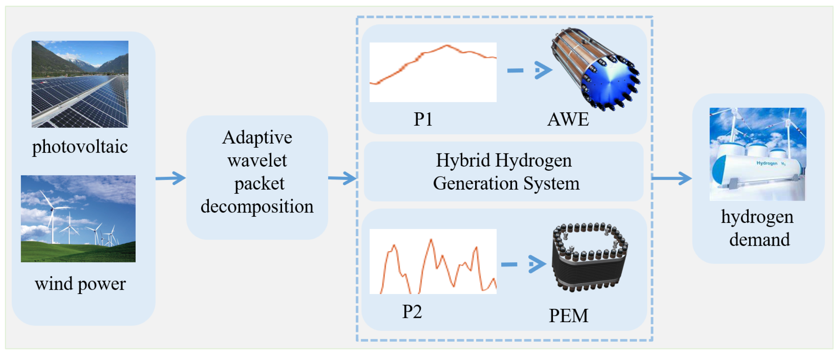
In order to improve the utilization rate of renewable energy, this research, starting from the volatility and complementarity of wind and photovoltaic power generation, creatively proposes a capacity optimization method based on bi-layer optimization for the cooperative operation of hybrid electrolysis tanks by taking advantage of the difference in the response speed of AWE and PEM electrolysis tanks to the fluctuating power. The main contributions of this paper are summarized as follows:
(1) In the hybrid electrolyzer operation process, according to the electrolyzer’s response speed to fluctuating power, it is proposed to use the adaptive wavelet packet decomposition method to decompose and reconstruct the wind power generation power, so that the AWE and PEM electrolyzers can be differentiated for power utilization.
(2) Based on the results of adaptive wavelet decomposition and reconstruction, a bi-layer optimization method is constructed. The objectives are minimizing the annual comprehensive cost of the hybrid hydrogen system in the upper layer and maximizing the consumption rate of the input power in the lower layer to configure the capacity of the hybrid electrolyzer. This allows the electrolyzers to match the volatility of the renewable energy generation power and fully utilize the characteristics of the respective electrolyzers.
The reminder of this paper is organized as follows:
Section 2 introduces the working principle of adaptive wavelet packet decomposition, as well as the process of adaptive decomposition and reconstruction.
Section 3 describes the bi-layer optimization model for the hybrid electrolyzer, and
Section 4 presents an arithmetic example of a city in Liaoning Province for optimization analysis. By solving the optimization model, it is verified that this method not only improves the adaptability of renewable energy power generation but also significantly reduces the hydrogen production cost, improves the efficiency of renewable energy utilization, and enhances the coupling effect of wind–solar complementary power generation and electrolytic cells.
3. Wavelet Packet Decomposition
3.1. Principle of Wavelet Packet Decomposition
Wavelet packet [
33,
34] decomposition uses orthogonal wavelet basis functions to decompose the signal into components at different frequencies and time locations. In the decomposition process, the renewable energy generation power is decomposed into low- and high-frequency components; the low-frequency components are further decomposed while the high-frequency components are used as detail coefficients for the current level. The process is carried out recursively until the desired number of decomposition levels is reached. After that, it is reconstructed according to the decomposition coefficients to obtain the data that satisfy the conditions.
The wavelet packet decomposition coefficient’s expression is given below:
where
is the wavelet packet basis function,
n is the number of layers, and
k is the coefficient.
The low-frequency component and high-frequency component coefficient expressions are as follows:
where
and
are the low- and high-frequency coefficients, respectively,
is the scale function, and
is the wavelet function.
The low-frequency renewable energy generation power obtained by data reconstruction of the layer coefficients is as follows:
The high-frequency power is as follows:
N denotes the maximum number of decomposition layers.
3.2. Adaptive Wavelet Packet Decomposition
When applying wavelet packet decomposition technology for renewable energy power generation, one of the key challenges lies in the determination of the optimal number of decomposition layers and filter scales. If the number of decomposition layers is insufficient, the system will not be able to meet the variable power input requirements of the AWE electrolytic cell. Conversely, selecting an excessively large number of decomposition layers may result in capacity constraints for the auxiliary energy storage system, as the system may no longer be able to accommodate the decomposed power effectively. Similarly, the choice of filter scale also presents its own set of challenges: a filter scale that is too small may lead to excessive noise interference, whereas a filter scale that is too large may result in the loss of fine details in the signal. To address these issues, an adaptive wavelet packet decomposition method has been developed, which dynamically adjusts both the decomposition level and filter scale based on the fluctuation limits of the AWE electrolyzer’s input power. This adaptive approach involves decomposing the wind and photovoltaic power signals into low-frequency and high-frequency components. If the low-frequency component does not meet the input requirements of the AWE electrolyzer, the decomposition process is repeated with adjusted parameters until the optimal solution is achieved. The flowchart illustrating this adaptive wavelet packet decomposition algorithm is shown in
Figure 2.
The specific steps are as follows:
Step 1: Based on the time series characteristics of renewable energy power generation data, the initial filtering scale ( min) and the initial decomposition layer () number are set.
Step 2: Based on the technical parameter documentation of the AWE electrolyzer, determine whether the power output of renewable energy generation, denoted as , meets the power fluctuation limit of the AWE electrolyzer: if it meets this criterion, input the renewable energy generation power into the AWE electrolyzer, and if it does not meet it, then perform step 3.
Step 3: The input power is characterized, followed by layers of wavelet packet decomposition to obtain the low-frequency component coefficients and high-frequency component coefficients .
Step 4: From the wavelet packet decomposition result obtained in step 3, extract the low-frequency component coefficients and high-frequency component coefficients of the nth layer for reconstruction.
Step 5: Judge whether the low-frequency component after reconstruction by n-layer wavelet packet decomposition satisfies the AWE electrolyzer power fluctuation limit: if not, then make the low-frequency component . Repeat step 2 to carry out the wavelet packet decomposition of layers, and when the fluctuation limit is satisfied, the optimal number of layers of the wavelet packet decomposition is adaptively determined to be n, and step 6 is executed.
Step 6: Roll the filter scale and repeat steps 2, 3, 4, and 5 until all data are covered. Splice the power of all windows into a complete sequence. Determine whether the AWE electrolyzer power fluctuation limit is satisfied: if so, proceed to step 7, and if not, , and return to step 2.
Step 7: Allocate this power to the AWE electrolyzer.
Through adaptive wavelet packet decomposition, the obtained low-frequency component
is the power
of the AWE electrolytic cell, and the high-frequency component
is the fluctuating power
of the PEM electrolytic cell. That is,
Through the adaptive wavelet packet decomposition, the optimal number of layers of wavelet packet decomposition can be determined even in the face of different regions of renewable energy generation power output, avoiding other problems caused by the fixed number of decomposition layers and enhancing the general applicability of the wavelet packet decomposition method in the decomposition of renewable energy generation output power.
4. Hybrid Electrolyzer Bi-Layer Optimization Model
For the capacity optimization of a hybrid electrolytic water-to-hydrogen system for wind and photovoltaic power consumption, we propose a bi-layer optimization model, where the upper optimization objective is to minimize the average annual integrated cost of the hybrid hydrogen system, and the decision variables are the rated capacity sizes of the AWE electrolyzer and the PEM electrolyzer, while the lower model’s optimization objective is to maximize the rate of the input power consumption of the hybrid hydrogen system, and the decision variables are the respective operating power of the AWE and PEM. The decision variables are the operating power of the AWE and PEM electrolyzers. The upper and lower optimization models constrain and influence each other, and the model structure is shown in
Figure 3.
4.1. Initial Investment Cost
The main installations in a hybrid electrolyzer hydrogen production system include an AWE electrolyzer and a PEM electrolyzer. The initial investment cost of the electrolyzers is proportional to the installed electrolyzer capacity. In order to simplify the calculation, the initial investment cost of the remaining devices in the system is calculated as 10% of the investment cost of the electrolyzers. Then, the investment cost calculation formula is as follows:
where
is the total investment cost of the system;
is the initial investment cost of the electrolyzer;
is the initial investment cost of the remaining units;
and
are the rated capacities of the AWE and PEM electrolyzers; and
and
are the unit capacity costs of the AWE and PEM electrolyzers.
4.2. System Operating Costs
The hybrid hydrogen system consumes mainly electricity and water to produce hydrogen during operation, so the operating costs are modeled as follows:
where
is the total cost of operating the system;
and
are the operating costs of the AWE and PEM electrolyzers, respectively;
and
are the prices of electricity and water at that moment in time, respectively;
and
are the electricity consumed by the AWE and PEM electrolyzers at that moment in time, respectively; and
and
represent the water consumed at that moment in time, which have the following relationship with the electricity consumed:
where
and
are the ratios of water to electrical energy consumed for hydrogen production by the electrolysis of water in the AWE and PEM electrolyzers.
4.3. Control Costs
Since the power input to the electrolyzer has a certain fluctuation, when the input power is greater than the dynamic response characteristics of the electrolyzer, the AWE electrolyzer can accept a power fluctuation range of ±20% and the PEM electrolyzer has a good response speed, so it is assumed that the entirety of the input power is acceptable for the fluctuation range of the PEM electrolyzer. Then, the control cost is
where
and
are the segmentation penalty coefficients, with values of 0.5 and 1.2, respectively. The sliding window variance volatility is expressed as
where
is the size of the sliding window, which determines the local scope of the volatility calculation, is the local index within the window to traverse the data points within the window, and
t is the time, which marks the current location of the calculation.
4.4. Revenue from Hydrogen Production Systems
Selling the hydrogen produced by the hybrid hydrogen system is the main source of income for the whole system, and the hydrogen produced can be used in the electric power system, industries, automobiles, etc. The economic model is as follows:
where
is the unit price of hydrogen at moment
t;
is the hydrogen production at moment
t.
4.5. Systematic Bi-Layer Optimization Model
Taking into account the dynamic response characteristics and costs of the two types of electrolyzers, a capacity optimization configuration model for the hybrid electrolyzer hydrogen production system was established. The objective function of the upper-layer optimization model is to minimize the total cost of the hybrid hydrogen production system in the first year, and the decision variables are the rated capacities of the AWE and PEM electrolyzers. The objective function can be expressed as
where
represents the cost calculated using the average life method of depreciation.
The upper-layer objective constraints are
where
denotes the maximum renewable energy generation power.
The lower-layer optimization objective is to maximize the consumption rate of the hybrid hydrogen production system, and the decision variables are the real-time operating power of the AWE and PEM electrolyzers. The objective function expression is as follows:
where
is the total system dissipation rate.
The lower-layer objective constraints are
The net present value (NPV) is used to assess the economic benefits of the system.
where
is the present value of future net cash flows,
is the present value of the original investment,
M is the discount rate, and
T is the life cycle.
4.6. Optimization Process
In the bi-layer optimization model of the electrolyzer capacity for the hybrid hydrogen production system, the upper-layer optimization and lower-layer optimization are mutually nested and coupled. The upper-layer objective function is solved using the differential evolution algorithm, while the lower-layer optimization uses data at a 5-min frequency for optimization, which results in a large amount of data. Therefore, YALMIP in Matlab was used. The specific optimization process steps are as follows:
Step 1: Set the population size N = 50, the crossover rate to 0.8, and the mutation factor to 0.5, with two variables. Initialize the population, where each individual in the population represents the decision variables in the upper-layer optimization objective, namely and .
Step 2: Input the values of the upper-layer decision variables into the lower-layer optimization model. Through the YALMIP optimization toolbox, calculate the real-time operating power of the alkaline electrolyzer and the proton exchange membrane electrolyzer under the configured rated power of the electrolyzer and input it into the upper-layer optimization model to obtain the absorption rate value.
Step 3: Based on the operating power obtained from the lower layer, combined with the upper-layer objective function, calculate the fitness of the individual, and determine whether the termination condition is met. If satisfied, terminate the iteration; if not, continue to step 4.
Step 4: Update the population individuals using the differential evolution algorithm. Then, repeat steps 2 and 3. After reaching the maximum number of iterations, select the individual with the best fitness in the population as the optimal capacity configuration of the hybrid electrolyzer.
5. Analysis and Discussion of Results
Based on the concept of collaborative operation of hybrid electrolyzers, a hydrogen production system based on renewable energy consumption was established. The influence of electrolyzer capacity configuration on the dynamic operation characteristics of the system was discussed, and an in-depth analysis was conducted based on the situation of renewable energy generation in a certain city in Liaoning Province.
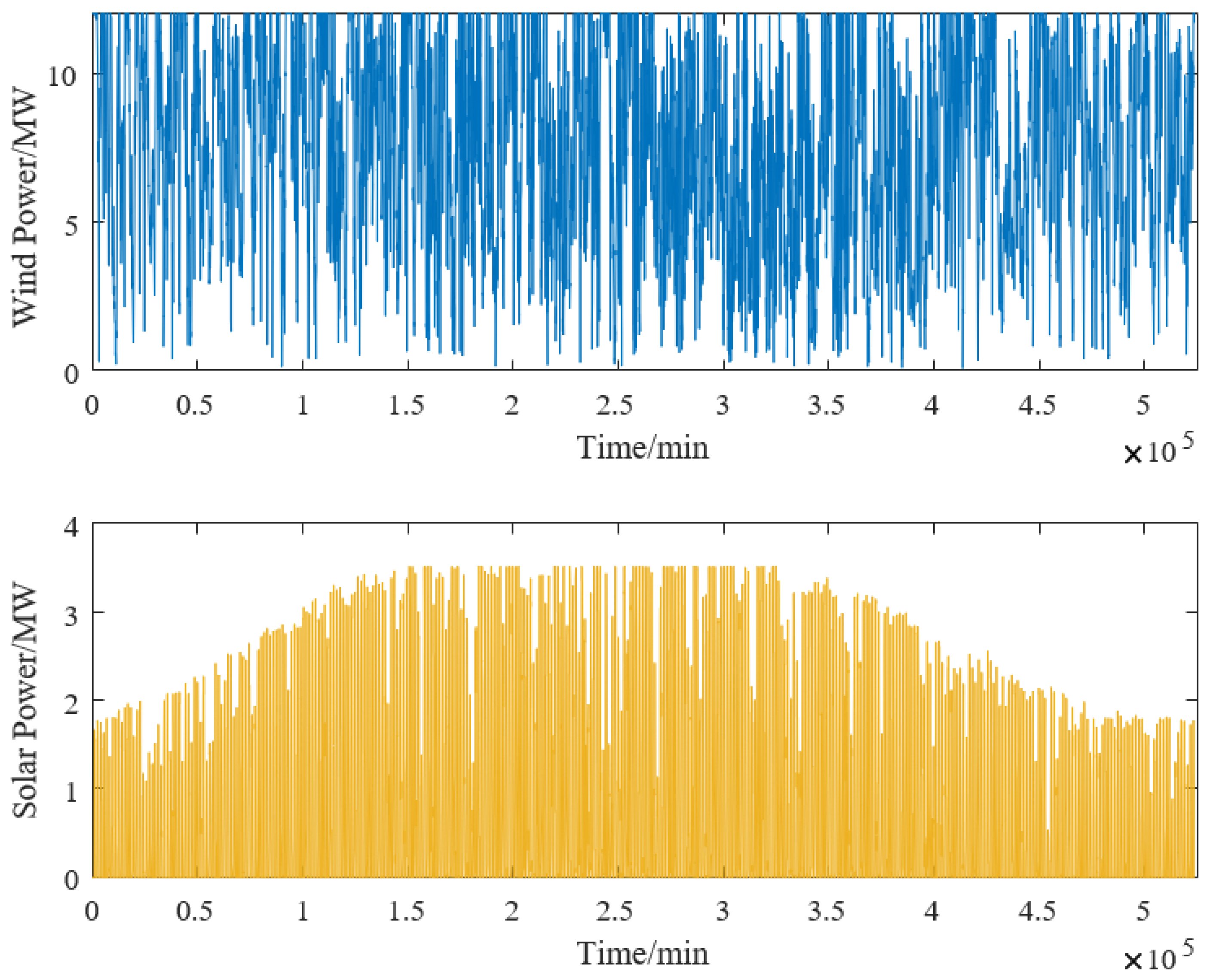
5.1. Analysis of Data Characteristics of Examples
Based on the data of renewable energy power generation in a certain area of Liaoning Province, the characteristics of the power generation were analyzed. The annual power generation situation is shown in
Figure 4.
To simplify the calculation, the K-MEANS clustering algorithm was applied to obtain the renewable energy power generation capacities of four typical days for each season, as shown in
Figure 5.
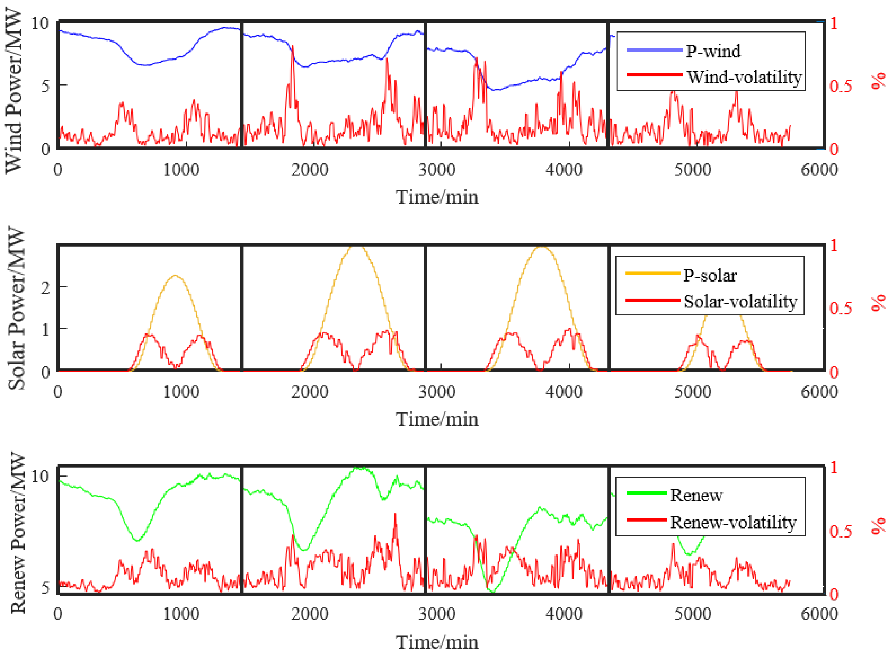
Figure 6 shows the power output of four typical days as continuous input and compares and analyzes the degree of fluctuation.
As can be seen from
Figure 6, the average fluctuation rate of the wind power generation is 31.35%, and the maximum fluctuation rate is 50.01%; the average fluctuation rate of the photovoltaic power generation is 27.25%, and the maximum fluctuation rate is 33.59%; the average fluctuation rate of the complementary power is 29.22%, and the maximum fluctuation rate is 39.32%. The current unit purchase cost price of the electrolytic cell is shown in
Table 1 [
35].
5.2. Adaptive Wavelet Packet Decomposition
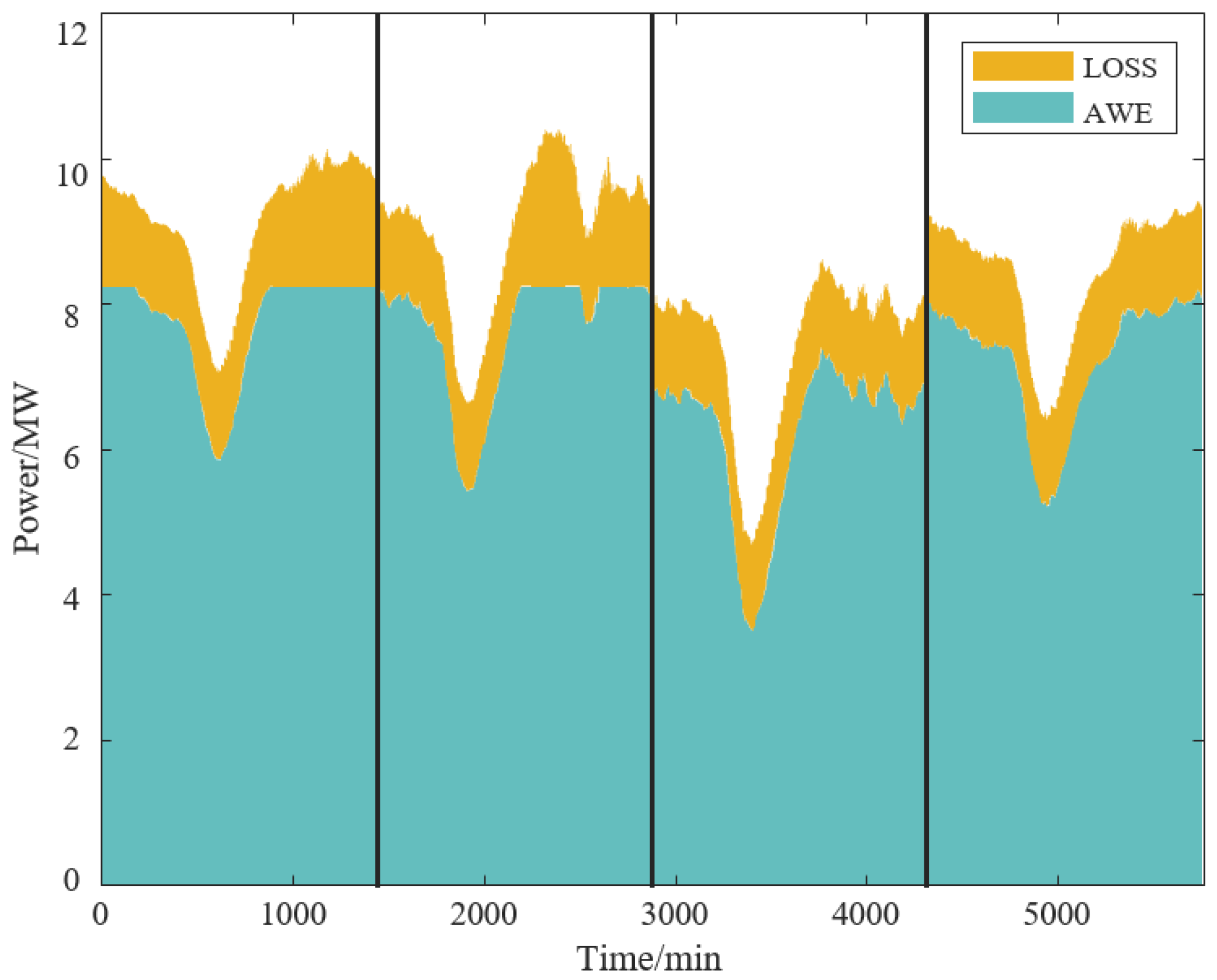
The power decomposition technology of adaptive wavelets precisely adapts to the complex characteristics of non-stationary signals such as renewable energy power generation data by dynamically adjusting the wavelet basis functions and the number of decomposition layers. During the processing, it utilizes the multi-resolution analysis capability to effectively extract signal features from different frequency bands, achieving the separation of power fluctuation details. After performing adaptive wavelet packet decomposition and reconstruction on the original power data, as shown in
Figure 7, it can be clearly seen that the reconstructed data retains the main features of the signal while smoothing out high-frequency noise and severe fluctuations. The fluctuation comparison in
Figure 8 is more intuitively displayed, showing that the processed data has significantly reduced fluctuation amplitude, which better meets the stable operation requirements of equipment such as AWE electrolyzers.
The adaptive wavelet packet decomposition algorithm dynamically adjusts the decomposition parameters to decompose the power signal of renewable energy into multiple frequency bands, effectively extracting and optimizing the low-frequency components. The simulation results are shown in
Table 2. After being processed by the algorithm, the average amplitude of power fluctuations is reduced, and the fluctuation range of the low-frequency components is controlled within the allowable limit of the AWE electrolyzer. Compared with the original data, it fully verifies its significant effect in smoothing power fluctuations and ensuring the stable operation of the AWE electrolyzer.
5.3. Operating Characteristics of Electrolytic Cells
In order to enhance the system’s adaptability to the fluctuations in renewable energy power generation, a comprehensive study was conducted on the dynamic response characteristics of alkaline water electrolysis (AWE) and proton exchange membrane (PEM) electrolyzers. Considering the crucial role of rapid and stable startup behavior in integrating intermittent renewable energy, the cold-start response process of these systems was analyzed [
36]. As shown in
Figure 9, a detailed analysis of the cold-start dynamics laid the foundation for further optimizing the synergy between renewable energy input and electrolyzer operation and is conducive to more efficient utilization of renewable electricity for hydrogen production.
During the cold-start process of the electrolytic cell, the load power of the AWE electrolytic cell responds to the input power with a delay of approximately 30 min and reaches the rated power around 8 min. The load power of the PEM electrolytic cell during the cold start responds to the input power with a delay of approximately 5 min; it reaches the rated power around 30 s.
The response characteristics of the electrolytic cell during the hot start [
37] are shown in
Figure 10.
Based on the simulation of the electrolytic cell model, the dynamic characteristics of different electrolytic cells were obtained. The results are shown in
Table 3.
From the above, AWE electrolyzers have high response energy loss, limiting them to stable loads. PEM electrolyzers are 83.3% faster in cold starts and 96.7% faster in hot starts than AWEs. Leveraging their strengths via differentiated use enables hybrid electrolyzer collaboration.
5.4. Optimization Results of Capacity Configuration
To optimize the matching degree between electrolysis hydrogen production and wind–solar power generation, and to enhance the system’s energy efficiency and benefits, based on the annual meteorological conditions, the capacity of the hybrid electrolyzer is optimized using the differential evolution algorithm. To visually demonstrate the improvement of wavelet packet decomposition on energy efficient utilization and the collaborative economic efficiency of the hybrid electrolyzer, five capacity configuration methods are applied.
- I.
Do not decompose the power generation capacity of renewable energy sources; only configure AWE electrolyzers.
- II.
Do not decompose the power generation capacity of renewable energy sources; only configure PEM electrolyzers.
- III.
Decompose the power generation capacity of renewable energy sources; only configure AWE electrolyzers.
- IV.
Decompose the power generation capacity of renewable energy sources; only configure PEM electrolyzers.
- V.
Decompose the power generation capacity of renewable energy sources, and configure the AWE and PEM hybrid electrolyzers.
The capacity configuration of the hydrogen production equipment in the system and the overall characteristics of the system are shown in
Table 4.
The differential evolution algorithm was used to solve each configuration method, and it was compared with the hybrid electrolytic cell. The results showed that in the case of no power decomposition, the investment cost of a single AWE electrolytic cell was the lowest, but the energy consumption rate was only 82.45%. However, due to the large fluctuation in the input power, the control cost was relatively high, and the unit hydrogen production cost was 34.4 CNY/kg. The investment cost of a single PEM electrolytic cell was higher. Due to its fast response speed, the energy consumption rate reached 90.07%, but the unit hydrogen production cost was the highest, at 40.1 CNY/kg. After the power generated by renewable energy was decomposed via the wavelet packet method, a single AWE electrolytic cell was used for the configuration. Due to the decomposition, the energy consumption rate decreased by 7.08%, but the unit hydrogen production cost also decreased by 6.91%. A single PEM electrolytic cell was applied, and its rated capacity decreased by 3.12%, but the energy consumption rate increased by 17.77%, and the hydrogen production cost also increased by 20.01%. Finally, the hybrid electrolytic cell system achieved a unit hydrogen production cost of only 30.4 CNY/kg, representing an 11.6% reduction compared to the single AWE system and a 24.2% reduction compared to the single PEM system, while significantly outperforming the IEA industry benchmarks (AWE: 22.8 CNY/kg; PEM: 37.6 CNY/kg), thereby demonstrating the lowest cost among the five configuration methods evaluated.
Net present value (NPV) is mainly influenced by cash flow, discount rate, and project lifespan. For this paper, we assumed that the discount rate remained constant at 8% and the project lifespan was 20 years. The study examined the changes in the NPV of various configurations under different cash flow scenarios. The comparison results are shown in
Figure 16.
Due to the insufficient growth rate of future cash flows in each case, the NPV curve shows a downward trend over time. However, from the graph, it can be concluded that among the five configuration methods, the NPV of the mixed electrolytic cell is the largest, while that of the single PEM electrolytic cell without wavelet packet decomposition is the smallest. The other configuration methods fall between these two extremes. Thus, it can be concluded that the capacity configuration of the mixed electrolytic cell has better economic performance compared to the single electrolytic cell.
In order to conduct a thorough study on the influence of the capacity ratio of PEM electrolyzers on the unit hydrogen production cost, by changing the capacity ratio of PEM electrolyzers, the trend of the unit hydrogen production cost was observed. The results are shown in
Figure 17.
From the simulation results, it can be seen that as the proportion of PEM electrolyzers increases, the unit hydrogen production cost decreases. When the proportion reaches around 10.5%, the unit hydrogen production cost is the lowest. After that, due to the influence of the cost of PEM electrolyzers, as the proportion of PEM electrolyzers increases, the unit hydrogen production cost also increases. The impact of electricity price on the unit hydrogen production cost is less than that of the proportion of PEM capacity.
6. Conclusions
Coupling electrolysis water-splitting for hydrogen production is an important technical means to achieve stable and diversified utilization of renewable energy sources. To improve the utilization rate of renewable energy, a hydrogen replenishment system for the coordinated operation of hybrid electrolyzers based on bi-layer optimization was proposed.
(1) Wind and photovoltaic power generation have certain complementarity in their time scales. When wind power generation decreases during the day, photovoltaic power generation can effectively supplement the energy of the hybrid hydrogen production system, preventing the input power of the electrolyzer from being too low and improving the utilization efficiency of the electrolyzer.
(2) Adaptive wavelet packet decomposition technology was used to optimize the distribution of the renewable energy generation power. By dynamically adjusting the wavelet basis functions and the number of decomposition layers, this method can effectively smooth the fluctuations of renewable energy generation power, reducing the volatility from 22.1% to 10.4%, which meets the stable operation requirements of the AWE electrolyzer. The low-frequency components are allocated to the AWE electrolyzer, and the high-frequency components are allocated to the PEM electrolyzer. This differentiated utilization method fully exploits the advantages of the two types of electrolyzers and enhances the adaptability and flexibility of the system.
(3) By establishing a bi-layer optimization model, the system’s absorption capacity for renewable energy generation and hydrogen production efficiency were significantly improved, and the hydrogen production cost was reduced. Through differential evolution algorithm optimization of the capacity of the hybrid electrolyzer hydrogen production system, the results show that the total capacity of the hybrid hydrogen production system is 9.21 MW, with the capacity ratio of the AWE and PEM electrolyzers being 89.5% and 10.5%, respectively. The optimized absorption rate reaches 90.12%, the total hydrogen production is 1293.18 tons/year, and the hydrogen production cost is 30.4 CNY/kg. Compared with the hydrogen production systems of single electrolyzers under four capacity configurations, the hybrid collaborative hydrogen production system shows significant advantages in investment cost, renewable energy absorption rate, and hydrogen production cost, proving the efficiency and economy of the coordinated operation of hybrid electrolyzers.
(4) Future research would focus on developing an electrode wear model and integrating it with dynamic market simulations to further optimize the system.


 ,
, 


