1. Introduction
After the Second World War, the number of gas turbines (GT) grew dynamically in industry and aviation. Thanks to advances in materials technology and modern finite element simulation methods in the past 30 years, gas turbines are now produced with high efficiency and long lifetime [
1]. In the energy sector, heavy-duty gas turbines for power plants cannot be replaced by reciprocating engines because of the high thermal efficiency resulting from their combined cycle use [
2]. Gas turbines used in the energy industry are robust in design, and stationary operation ensures a long lifetime [
3]. In the aviation sector, there is currently no alternative due to the high flight speed and high altitude offered by propulsion engines [
3]. Commercial aviation is a global business of around 160.000 aircraft currently operating on a single fuel product which is presently sourced from fossil fuels, contributing around 3–4% of global carbon emissions. The main criteria for these power plants include high reliability, high performance, and tolerance of numerous starting procedures [
4].
The use of alternative fuels in gas turbines has become a key area of research and development, driven by global efforts to reduce greenhouse gas emissions, enhance energy security, and transition toward sustainable energy systems. Gas turbines, used widely in both power generation and aviation, rely heavily on fossil-based fuels. However, environmental regulations and decarbonization policies are pushing industries to seek viable alternatives [
5].
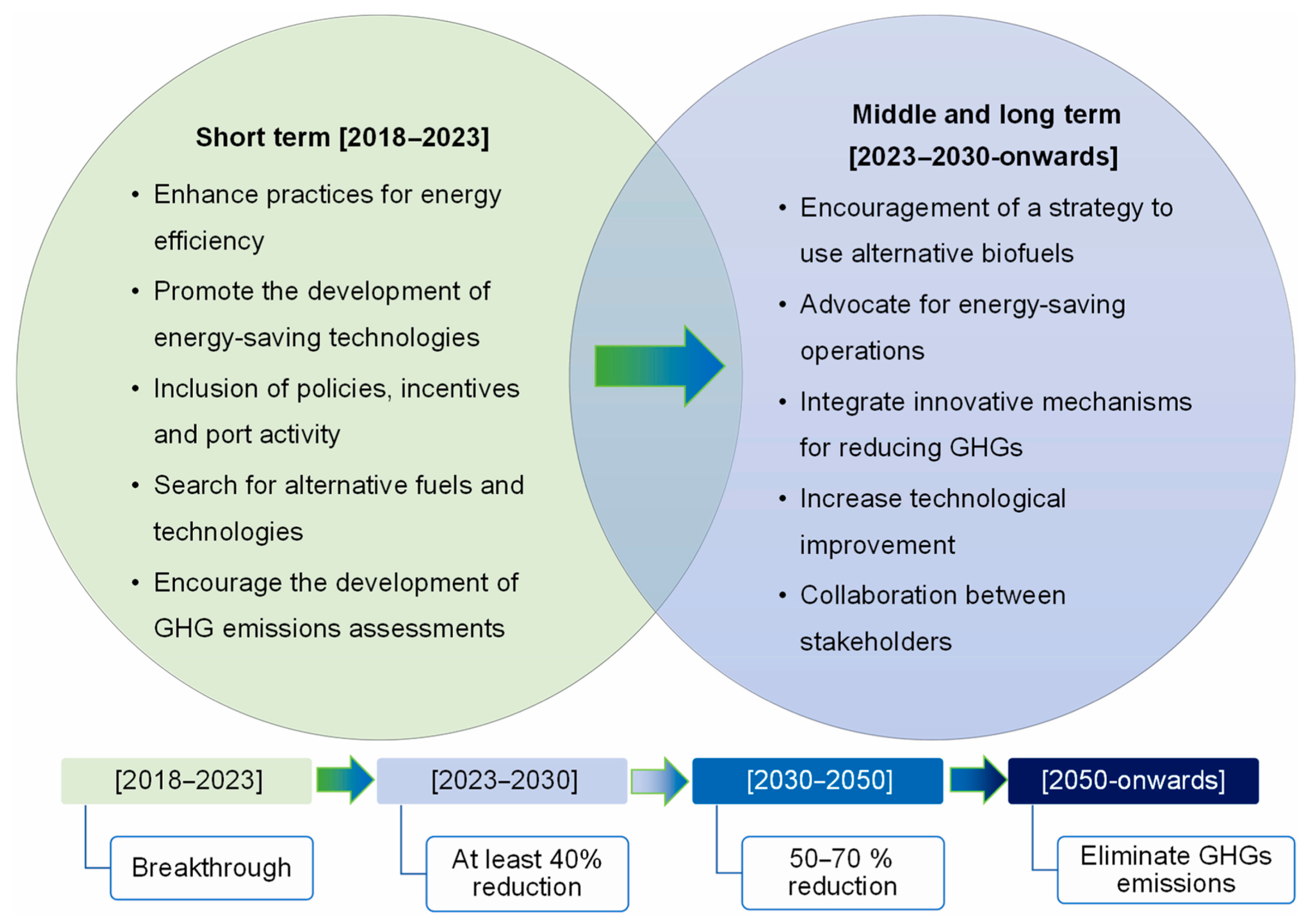
In the international context, governments and organizations such as the International Civil Aviation Organization (ICAO), the International Energy Agency (IEA), and the European Union (EU) have played significant roles in shaping policies and promoting low-carbon fuel use. The Carbon Offsetting and Reduction Scheme for International Aviation (CORSIA), for example, encourages the adoption of sustainable aviation fuels (SAFs), while the EU’s Renewable Energy Directive (RED II) sets mandates for renewable fuel usage across sectors [
6]. The reduction in the rate of greenhouse gas emissions is illustrated in
Figure 1.
Countries like the United States, Germany, China, and Japan are at the forefront of these developments. In the U.S., the Federal Aviation Administration (FAA) supports SAF research through its Continuous Lower Energy, Emissions and Noise (CLEEN) program [
7]. Germany’s “PtL” (Power-to-Liquid) initiatives focus on producing synthetic fuels from renewable electricity, while China is investing heavily in hydrogen infrastructure and biofuel production [
8].
Research trends in recent years have concentrated on various alternative fuels, including biofuels, hydrogen, synthetic fuels (e-fuels), and natural gas derivatives like LNG and CNG. Biofuels, derived from waste and biomass, have been widely tested and approved for blending with conventional jet fuels. Hydrogen, while offering zero-carbon emissions at point of use, poses challenges in storage, safety, and retrofitting existing engines. Synthetic fuels produced from renewable energy sources are gaining attention for their compatibility with existing turbine infrastructure [
9].
Standardization is crucial for widespread adoption. Organizations like ASTM International have approved multiple blends of SAFs under standards such as ASTM D7566, ensuring safety and performance in aviation gas turbines. These standards enable “drop-in” fuel use without engine modifications, which is essential for cost-effective implementation. [
10] The contribution on transport sectors on GHG emissions, air pollutants and progression on CO
2 eq. emissions and projections per sector are shown at the
Figure 2.
Figure 2.
Contribution on transport sectors on (
a) GHG emissions, (
b) air pollutants and (
c) progression on CO
2 eq. emissions and projections per sector. Database: European Environmental Agency, Eurostat. The
Table 1 shows the classification of different fuels according to molecular composition, calorific value and physical state [
11].
Table 1.
Classification of fuels.
Table 1.
Classification of fuels.
| Classification of Fuel | Typical Composition | LHV [MJ/kg] | Typical Specific Fuels |
|---|
| Ultra Low LHV gaseous fuels | H2 < 10% | | Blast furnace gas |
| CH4 < 10% | <11.200 (<300) | Inert gas |
| N2 + CO ˃ 40% | | Biogases |
| High hydrogen gaseous fuels | H2 ˃ 50% | 5.500–11.200 | Refinery gas
Petrochemical gas |
| CxHy = 0–40% | (150–300) | Hydrogen power |
| Medium LHV gaseous fuels | CH4 < 60% | | Weak natural gas |
| N2 + CO2 = 30–50% | 11.200–30.000 | Landfill gas, Coke oven gas, Corex gas |
| H2 = 10–50% | | |
| Natural gas | CH4 = 90%
CxHy = 5%
Inert = 5% | 30.000–45.000 | Natural gas Liquefied natural gas |
| High LHV gaseous fuels | CH4 and higher hydrocarbons
CxHy ˃ 10% | 32.000–45.000 | Liquid petroleum gas (butane, propane) Refinery off-gas |
| Liquid fuels | CxHy, with x ˃ 6 | 32.000–45.000 | Kerosene, Diesel oil, Naptha Crude oils, Residual oils, Bio-liquids |
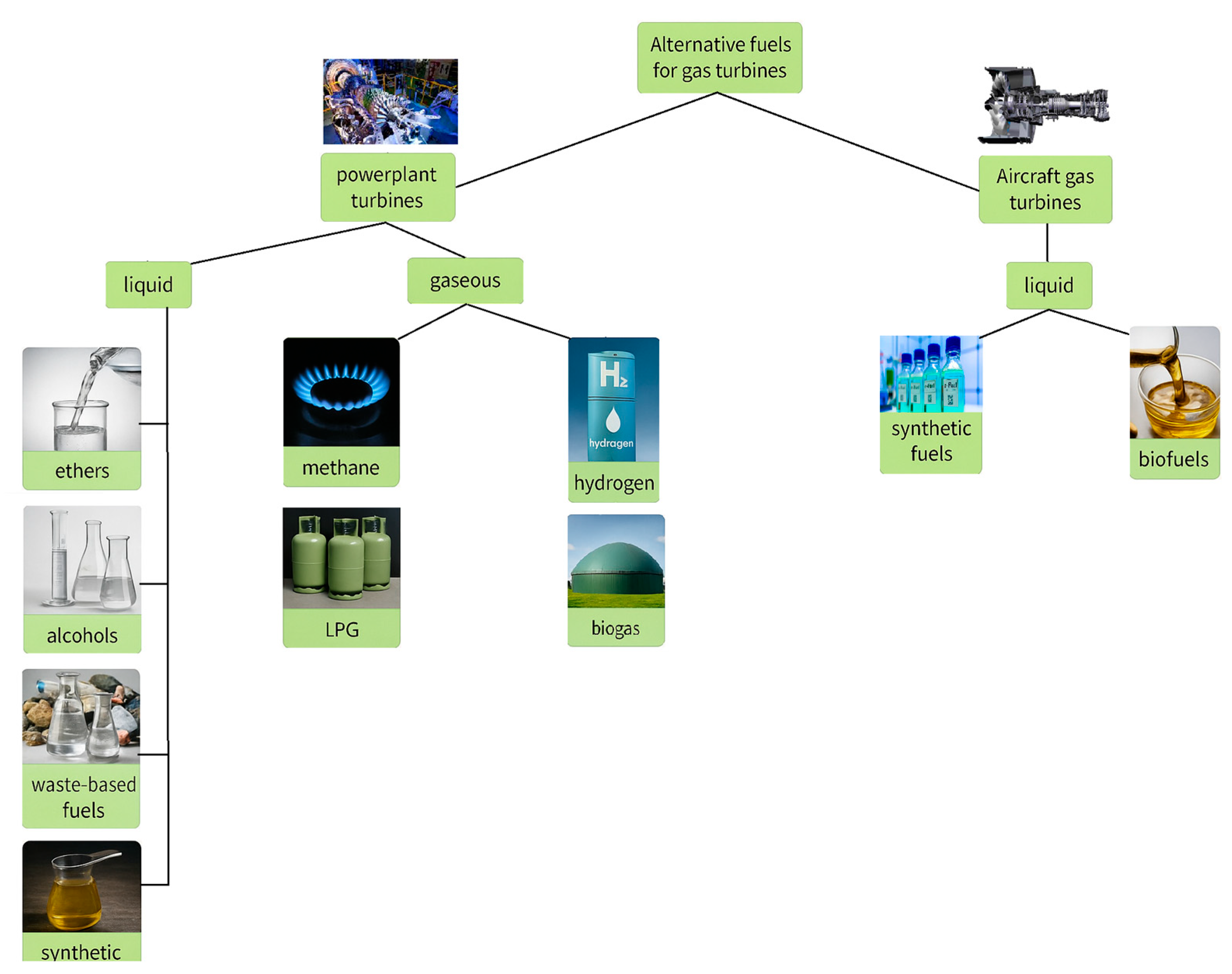
Gas turbines can run on either liquid or gaseous fuels, but only liquid fuels are appropriate for the aviation industry due to their storability. The main types of fuels used in gas turbine power plants are shown in the
Figure 3:
2. Principles and Background of Gas Turbines
Three forms of flame are distinguished in the literature: premixed, non-premixed, and partially premixed combustion. Premixed flames refer to the combustion mode when the fuel and oxidizer are mixed prior to burning. Non-premixed flames or diffusion flames refer to combustion mode when the fuel and the oxidizer are separated before entering the reaction zone where they mix and burn [
12]. In non-premixed or partially premixed combustion, the fuel and oxidizer are transported independently to the reaction zone, primarily by diffusion, where mixing of the fuel and oxidizer occurs prior to their reaction. After the fuel has been injected into the air stream created by the compressor the flow enters the flame area. Premixed fuel injection is a solution that can be used for both higher and lower calorific values of fuels. Such combustion chamber designs are used, for example, in GE’s Dry Low NOx natural gas-fired gas turbines. In lean operation, soot emissions and carbon dioxide emissions increase. Non-premixed or partially premixed fuel injection designs are applicable to all alternative fuels, both liquid and gaseous. This design allows for the combustion of multiple fuels as a stabilized premixed flame can ignite a lower calorific value fuel in the secondary zone [
10]. The design of the combustion chamber and nozzles is based on the fuel used (gas or liquid). If the gas turbine is not fueled with conventional fuels, mainly in industrial applications, a special exhaust of the combustion chamber is required, for example, when operating with low calorific value inert gas or pyrolysis oil [
13].
From the point of view of combustion stabilization, several designs have been used. These aim to reduce NOx emissions and increase fuel flexibility [
14].
According to the properties of the fuel injected, the fuel supply system and, most importantly, the combustion chamber design must be such that the flame distribution is homogeneous and combustion is steady state in the gas turbine at all operating conditions [
15]. Combustion chamber designs for gas turbines today aim to achieve low NO
x emissions. Because there is a constantly high combustion temperature in the reaction chamber, it is conducive to the formation of NO
x emission [
16]. One application for reducing combustion temperature and NO
x emission is the injection of water or steam into the combustion chamber. Another solution that does not require water injection is called ‘Dry Low NOx’ (DLN) or ‘Dry Low Emission’ (DLE) technologies [
17]. The DLN and DLE technologies both are lean premixed or partially lean premixed fuel–air injection systems. DLN technology was specifically developed for natural gas-fired power plant applications to reduce NO
x, while DLE technology is used in all new generation gas turbine combustion chambers, which, in addition to NO
x, also reduces CO
2 and unburned hydrocarbons [
18].
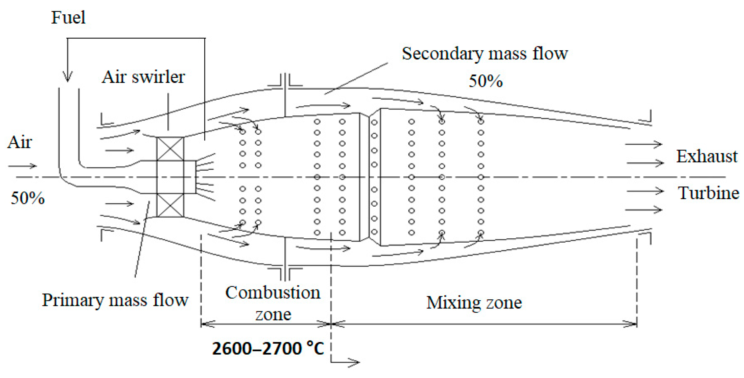
Figure 4 shows a lean premixed combustion chamber.
In aerodynamically stabilized combustors, the flow direction is axial. These combustor designs incorporate return flow zones to stabilize the flame. This method is used for premixed flames by incorporating swirling nozzles. These nozzles create a strong centrifugal flow [
19]. The swirling flow creates a central recirculation zone in which the hot combustion products are recirculated and mixed with the fresh reactants [
20].
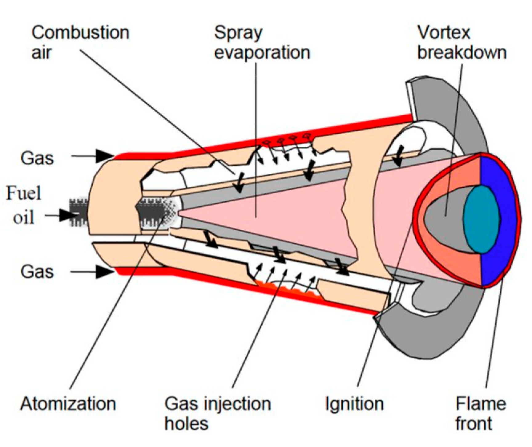
Figure 5. shows the ALSTOM/ANSALDO EV combustor, which operates with a vortex shedding stabilization mechanism.
Three main types of combustors can be distinguished: tubular, tubular ring, and ring design. The tubular design is a reverse-flow design. The airflow is bidirectional. A combustion chamber of this design is shown in
Figure 6. This is a reverse-flow tubular combustor developed by OPRA (Optimal Radial Gas Turbines) Turbines to efficiently burn low-calorific fuels in the OPRA16 gas turbine rated at 1.9 MW [
21]. These gas turbines are specifically designed to burn low calorific value fuels such as pyrolysis oil, biogas, carbon dioxide-rich inert natural gases, etc. [
22] They have centrifugal compressors and axial turbine stages. Compared to the standard burner used for burning fossil fuels in diffusion mode, this design has a larger volume to allow sufficient time for combustion to take place. The air distribution has also been changed to ensure adequate combustion rates for low calorific fuels (such as inert gases, pyrolysis oils, biogases) [
23]. Another significant difference is the flame stabilization technique, which is now only provided by a radial swirler [
24].
Flameless Oxidation (FLOX
TM) is a self-ignition combustion technology. In FLOX or MILD combustion, flue gas (N
2, CO
2, H
2O) is recirculated within the combustion chamber towards the flame front to reduce the O
2 concentration in the oxidant and to heat the reactants above the auto-ignition temperature [
25,
26,
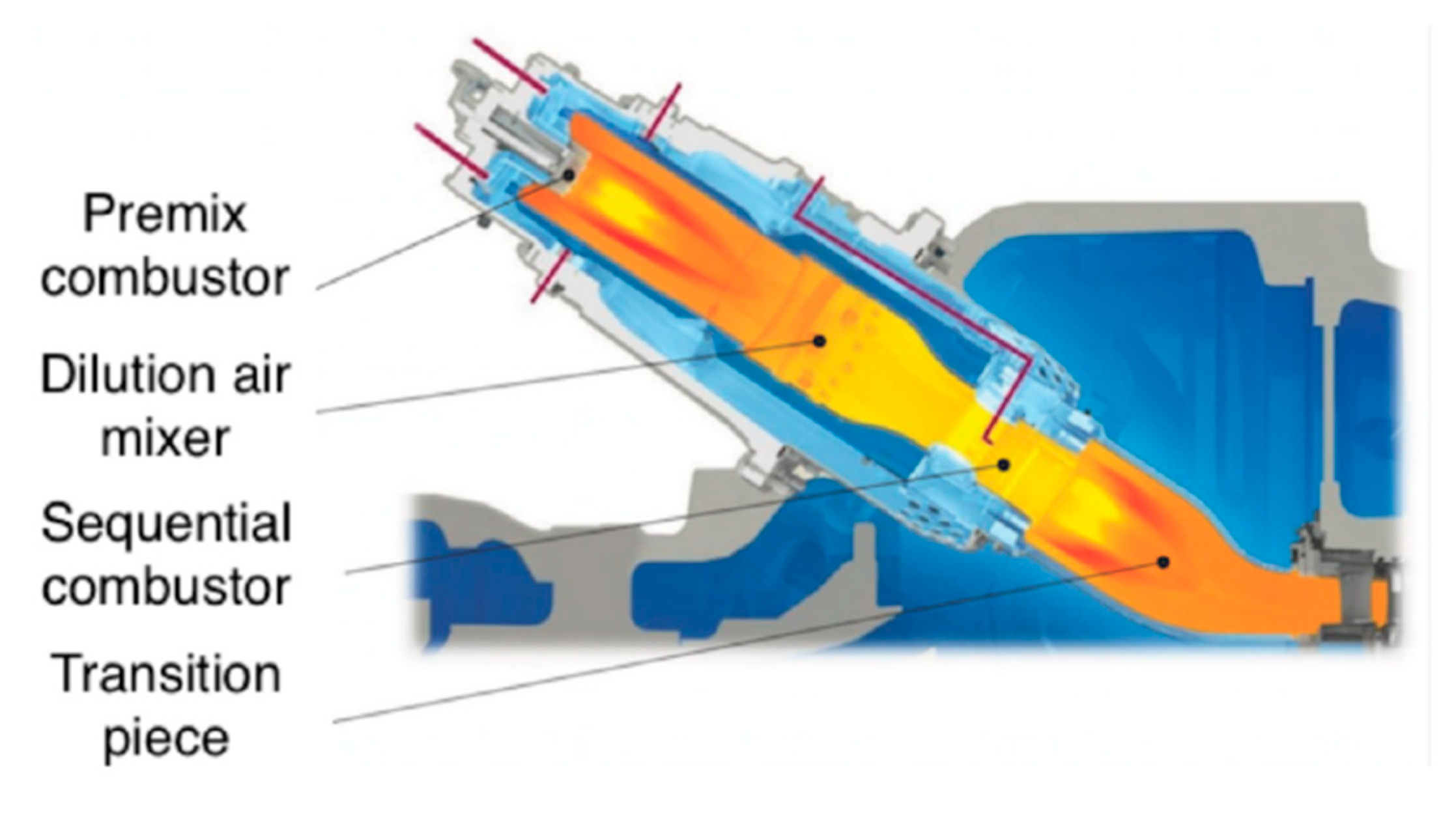
27]. Another solution is to use multi-stage combustion chambers [
28]. In these, the reaction zone is divided into two parts, a zone with a high equivalence ratio (first stage) and a zone where the equivalence ratio is lower (second stage). In the first stage, the average equivalence ratio is 1.4 where no NO
x concentration is formed due to low temperature and oxygen concentration, and then in the second stage, a lean mixture is formed by adding secondary air where NO
x formation can be kept low by controlling the air flow [
29]. Nowadays, longitudinal axial flow combustion chambers are widespread in high power gas turbines [
30,
31,
32,
33].
Figure 7. shows a multistage combustion chamber design; such designs are used in Siemens, Ansaldo, and GE gas turbines.
The impact of different fuel types on atomization and evaporation was examined for kerosene, biodiesel, and biodiesel/bio-oil blends, focusing on how spray characteristics influence combustion performance in a typical gas turbine vortex combustor. Compared to kerosene, biofuels exhibited narrower spray angles and larger droplet sizes, which delayed both evaporation and combustion. This led to increased emissions of soot and unburned hydrocarbons, as well as higher NOx levels due to the fuels’ elevated oxygen content.
Another investigation focused on the combustion performance of viscous sunflower oil as a biofuel, revealing that a blend containing up to 30% vegetable oil in diesel was viable for gas turbine operation, albeit with increased pollutant emissions. An alternative strategy for using pure vegetable oil involves preheating it to 70–130 °C prior to injection. Raising the fuel temperature significantly lowers its viscosity, which enhances spray quality, accelerates droplet evaporation, and improves combustion efficiency. This was confirmed by a study that demonstrated a linear relationship between CO
2 emissions and fuel viscosity during the direct use of preheated vegetable oil in a gas turbine [
34].
In contrast, pyrolysis bio-oil (PBO) cannot be used directly in gas turbine burners due to its unfavorable physical and chemical properties—such as high viscosity, acidity, high oxygen and water content, solid residues, non-volatile components, and chemical instability—which cause elevated particulate matter emissions and deposits from charring and coking. However, blending PBO with ethanol (50% by volume) has been shown to mitigate these issues. Furthermore, thermocatalytic reforming of bio-oil has significantly improved its fuel properties, making it more similar to fossil fuels and enabling its use in modified burners. This reformulated bio-oil has shown much lower CO2 emissions compared to untreated PBO, although it still results in higher NOx emissions due to its nitrogen content.
In conclusion, low-quality liquid biofuels generally require either preheating or blending with fossil fuels to be suitable for gas turbine combustion. To date, no published studies have introduced combustion chamber designs capable of stably burning cold liquid biofuels—such as unheated vegetable palm oil—without blending or pre-treatment, while still meeting acceptable emission standards.
3. Background and Limitations of Traditional Gas Turbine Fuels
For decades, these turbines have relied heavily on traditional fossil-based fuels such as kerosene (Jet A-1) for aviation and natural gas or diesel for industrial turbines. While these fuels offer high energy density and operational reliability, they also pose growing environmental and sustainability challenges.
The primary appeal of traditional gas turbine fuels lies in their well-established infrastructure, global availability, and favorable combustion properties. In aviation, Jet A and Jet A-1 fuels perform reliably across extreme temperatures and altitudes, providing consistent power during takeoff, cruise, and landing. In industrial power generation, natural gas enables rapid startup, high efficiency, and lower emissions compared to coal or oil.
However, the continued use of these fuels comes with significant drawbacks, the most urgent being greenhouse gas (GHG) emissions. Combustion of fossil fuels releases large amounts of carbon dioxide (CO
2), the primary contributor to global climate change. While natural gas emits less CO
2 than coal or oil, it still contributes to the warming of the planet. Moreover, methane leaks during extraction and transportation further exacerbate the problem, as methane is a far more potent GHG than CO
2 over short timescales [
35].
Aviation gas turbines are also major emitters of CO2 and nitrogen oxides (NOₓ), especially on long-haul flights. In addition to GHGs, aircraft engines produce contrails and high-altitude particulates that affect atmospheric chemistry and may amplify global warming. Industrial gas turbines, particularly those running on diesel or heavy fuels in remote locations, also emit NOₓ, sulfur oxides (SOₓ), and fine particulates, contributing to air pollution and human health risks.
Sustainability is another major concern. Fossil fuel reserves are finite, and their continued extraction often causes environmental degradation. The aviation industry currently depends almost entirely on fossil-based jet fuels, which raises serious questions about long-term energy security. In the industrial sector, while some turbines have been adapted to run on biogas or hydrogen blends, full-scale transition remains limited by cost, technology maturity, and infrastructure constraints.
Operational limitations also affect both aircraft and industrial gas turbines. In aviation, strict requirements for thermal stability and low-temperature fluidity limit the range of acceptable fuel compositions. Turbine fouling, coking, and corrosion from fuel impurities lead to reduced efficiency and higher maintenance needs. In power generation, load fluctuations and cycling operations can accelerate wear and tear, especially when burning low-quality fuels.
Additionally, fuel price volatility poses economic risks. Global markets are sensitive to geopolitical instability, which affects both aviation and energy costs. Airlines and utility operators must contend with unpredictable fuel expenses, impacting profitability and long-term planning [
36].
Despite these challenges, efforts are underway to develop more sustainable alternatives. Sustainable aviation fuels (SAFs), synthetic fuels, and hydrogen offer promising pathways, but they face hurdles in scalability, regulatory approval, and infrastructure compatibility. Similarly, industrial turbines are beginning to integrate low-carbon fuels, yet most systems are still optimized for traditional hydrocarbons [
37].
While traditional gas turbine fuels have supported global development for decades, they are no longer compatible with the urgent demands of climate responsibility, energy security, and operational sustainability. A successful transition to alternative fuels requires coordinated innovation, policy support, and investment in new technologies across both aviation and industrial sectors.
4. Liquid Fuels for Gas Turbines
Traditionally, liquid fossil fuels have powered these turbines. In aviation, Jet-A and Jet-A1 kerosene-based fuels are standard because of their high energy density, low freezing point, and well-established global infrastructure. In industrial turbines, diesel and light fuel oils are commonly used, especially in remote or backup applications. However, environmental concerns, especially CO
2 and NOx emissions, have driven interest in alternative fuels [
38]. Biofuels like HEFA (Hydroprocessed Esters and Fatty Acids), FT-SPK (Fischer–Tropsch Synthetic Paraffinic Kerosene), and alcohol-to-jet (ATJ) fuels have emerged as potential replacements. These fuels are derived from renewable sources such as plant oils, waste biomass, and alcohols, and several of them are already approved for use in commercial aviation in blends up to 50%. Research has also focused on synthetic fuels made through gas-to-liquid (GTL) and coal-to-liquid (CTL) processes, offering drop-in alternatives with reduced sulfur and aromatic content. Hydrogen, despite storage and combustion challenges, is gaining attention due to its potential for zero-carbon emissions [
39]. Recent studies investigate hydrogen-blended fuels in industrial turbines, showing promising combustion stability with low NO
x output. Material compatibility, fuel system modifications, and combustion dynamics are key research areas. For example, researchers are studying the effect of biofuels on turbine blade corrosion, thermal efficiency, and flame characteristics [
40].
4.1. Alcohols
Alcohols used as fuels in gas turbines are compounds with carbon numbers ranging from 1 to 4. The most cost-effective among them is methanol (CH
3OH), which is typically produced through the catalytic synthesis of synthesis gas—a mixture of carbon monoxide, carbon dioxide, and hydrogen—derived from natural gas, coal, or biomass. Methanol may contain sulfur, nitrogen, aromatics, and olefins only as trace impurities [
41]. It has a high octane number and a low cetane number. Although it has a low ozone-forming potential, methanol is highly toxic and corrosive. A major drawback is that it forms formaldehyde during combustion, which is also toxic. Other disadvantages include low flammability, high heat of vaporization, poor lubricity, and high volatility. Mixing methanol with conventional fuels requires additives to homogenize the two miscible phases. Its use has the advantage of lower NO
x and particulate emissions, and it also improves co-emissions. Produced from biomass, it reduces carbon dioxide emissions [
42].
Another large group of alcohols is ethanol (ethyl alcohol CH
3-CH
2-OH), one of the oldest fuels used in internal combustion heat engines. It is also often called bioethanol to distinguish it from one obtained by chemical synthesis. Its properties allow it to be used as a fuel in a number of ways: on its own, as a blending component in conventional motor fuels, as an additive, as a bio-derived additive, as a bio-derived blending component, or as a molecular component of additives [
43]. For use as a fuel, biochemical and synthetically produced ethanol have the same quality characteristics. Ethanol has a favorable carbonyl/hydrogen ratio and a high oxygen content. The latter results in a significantly lower stoichiometric air/fuel mass and volume ratio. Its density is more in the range typical of petrol. Its boiling point is closer to that of the light petrol fraction. It has a high heat of vaporization and a lower calorific value than conventional fuels. In contrast to petroleum-based fuels, it has unlimited water solubility. Its high experimental octane number is favorable, but it also has high sensitivity. Its biodegradability is an advantage, making its use as a fuel attractive in the face of tightening environmental regulations. Ethanol’s properties make it closer to gasoline than to kerosene or diesel fuels.
The parameters of ethanol compared to conventional fuels are shown in the
Table 2 [
44].
Ethanol can be produced in two ways. One is chemical synthesis, where ethylene is obtained by direct or indirect hydration, methanol homologation or from synthesis gas [
45]. The other method is biochemical, whereby ethylene is produced from sugars by fermentation or hydrolysis of starch or cellulose. The use of alcohol in gas turbines is not widespread because of their low calorific value and significant differences in their evaporative properties [
46].
4.2. Ethers
Ethers from alternative sources that can be used as engine propellants are used either alone or as blending components. The most important are dimethyl ether (DME), methyl tertiary butyl ether (MTBE), ethyl tertiary butyl ether (ETBE, bio-ETBE), tertiary amyl methyl ether (TAME) [
47].
Dimethyl ether can also be used on its own to power gas turbines. Its main advantages are a high cetane number and lower air/fuel ratio. It mixes well with both diesel and kerosene [
48]. Its production is based on synthesis gas or methanol (conventional process). Its advantages include the fact that it can be produced from both fossil and renewable energy sources (biomass, waste), which increases the security of energy supply. Blending DME produced from natural gas with biomass does not change the properties of the propellant, so the ratio of fossil to bio-derived propellant can be gradually increased in favor of the latter. It has a high oxygen content, a low carbon/hydrogen ratio and no carbon–carbon bonding, so it produces less soot during combustion, i.e., low particulate emissions. It contains no toxic compounds such as pollutants. Its disadvantages include the need for additives to protect the injection system due to its low lubricity. Due to its high vapor pressure, it can cause cavitation in the injection system, which can cause the injection jet pattern to be interrupted, resulting in uneven injections. [
49].
MTBE is produced by the catalytic reaction of isobutene and methanol from various sources. It is at least 98.5% pure, contains no more than 0.1% hydrocarbons (C
4) and about 1.4% other oxygenates [
50].
ETBE, and blended bio-ETBE (produced using bioethanol), can be an excellent substitute for MTBE because of its favorable physical and chemical properties and because it contains ethanol of biomass origin in its structure [
51]. The advantages of bio-ETBE are that it contains molecules from renewable energy sources, lower vapor pressure, less soluble in water than MTBE, less toxic, lower CO emissions, no increase in NO
X emissions, reduced aromatic and olefin content [
52]. Disadvantages include a lower calorific value and the tendency to form peroxide during prolonged storage (which requires antioxidant additive) [
53].
Recent studies explore the feasibility and performance of alternative fuels, particularly dimethyl ether (DME) and methanol, in hybrid power generation systems and gas turbines. Cocco et al. investigated externally reformed solid oxide fuel cell-micro gas turbine (SOFC–MGT) hybrid systems fueled by methanol and DME. These systems aim for high efficiency in small-scale power generation (200–500 kW). External reforming of methanol and DME at lower temperatures (200–350 °C) improves system efficiency and hydrogen yield at the SOFC anode. Optimized reforming conditions achieved efficiencies up to 73% for methanol and 69% for DME [
54]. The study emphasized the importance of controlling the steam-to-carbon ratio (SCR), with optimal values around 1.0 for methanol and 1.5–2.0 for DME. Higher SCRs dilute hydrogen and reduce stack performance, while lower SCRs risk carbon deposition. Simulation results showed that methanol provides slightly better efficiency, while DME yields a higher power output at elevated reforming temperatures [
48]. Lee et al. tested DME in an industrial-scale GE7EA gas turbine. Compared to methane, DME showed good combustion stability and lower NO
x emissions. However, its different combustion characteristics require nozzle modifications. DME burns closer to the nozzle due to higher turbulent burning velocity and injection momentum, affecting flame shape and temperature profiles.
Despite lower combustion temperatures, DME proved to be a viable and cleaner alternative fuel, though further design adjustments are needed for full compatibility with existing turbine hardware. Starik et al. analyzed the environmental impacts of various alternative fuels, including DME, methanol, and biofuels, in gas turbines. DME showed promising reductions in CO and nitrogen oxide emissions compared to conventional Jet-A fuel, though it slightly increased emissions of HNO2 and HNO3.
In terms of CO
2 emissions, DME performed better than biodiesel or biobutanol but worse than cryogenic methane. Overall, DME and methanol offer favorable emissions profiles and efficiency, supporting their potential role in sustainable power generation [
55].
4.3. Biofuels
Vegetable oils and their derivatives belong to a large group of alternative fuels from renewable sources. Within this, they are classified as liquid biofuels (fuels that can be produced from biomass as a permanently renewable energy source). Vegetable oils are used on their own and blended with conventional fuels (diesel, kerosene). Fossil fuels are characterized by higher density and approximately eight times greater viscosity (worse atomization), lower calorific value, higher cold filterability limit temperature, free fatty acid content (corrosive effect), high iodine value, and lower sulfur content. Its advantages include that it can be used as a substitute for conventional fuels without modification, it is completely biodegradable and non-toxic, the efficiency of the engine is practically unchanged, the power output is almost the same, the concentration of sulfur compounds in the exhaust gas is very low (<10 ppm), it has a concentration of a few (5–20) percent, and it practically does not change the quality of conventional fuel, it is a renewable energy source. Disadvantages include that crop production requires significant amounts of chemicals, production requires significant amounts of fossil energy, and its limited availability, high iodine content, high water content causing corrosion, higher CFPP (cold filter plugging point) and higher viscosity; it also deteriorates after 3 months of storage and contains methanol and free OH compounds that cause corrosion [
56].
Enagi et al. emphasized that various liquid biofuels—including biodiesel, bioethanol, bio—oil, hydrogenated vegetable oil (HVO), and Fischer–Tropsch (FT) fuels—can be integrated into both Directly Fired (DFGT) and Externally Fired Gas Turbines (EFGT). Their study outlines biofuel production pathways such as transesterification, pyrolysis, gasification, and catalytic liquefaction, noting that advanced combustion techniques like Colorless Distributed Combustion (CDC), High Temperature Air Combustion (HiTAC), MILD, and catalytic combustion can reduce emissions during biofuel use [
56]. Chiong et al. provided a comparative evaluation of the combustion behavior and emissions of various biofuels in gas turbines. Their review highlighted that while FT fuels and HVO exhibit performance similar to Jet-A fuels and are suitable for aviation turbines, other biofuels such as biodiesel, bioethanol, bio-oil, and straight vegetable oil (SVO) require improvements in atomization and preheating for efficient combustion. High viscosity and low volatility were noted challenges, especially for SVO and bio-oil [
57]. Polatlı et al. conducted a numerical investigation on the use of biodiesel–JP4 mixtures in a high bypass ratio gas turbine engine. They analyzed thrust, energy, and total pressure under varying biofuel ratios. Results showed that increasing biodiesel content raised net thrust and improved efficiency by reducing exergy and pressure losses. The best performance was observed with higher biofuel concentrations, highlighting the viability of biodiesel as a cleaner alternative for aviation propulsion [
58].
4.4. Synthetic Fuels
The production of liquid synthetic hydrocarbon mixtures from synthesis gas has become widespread under the name “Gas to Liquid Technology” (GTL). The basic process is the Fischer–Tropsch (FT) synthesis is a chemical process that converts synthesis gas (CO and H
2) into liquid hydrocarbons. This process was used to produce gasoline from synthesis gas obtained from coal between the two world wars [
59].
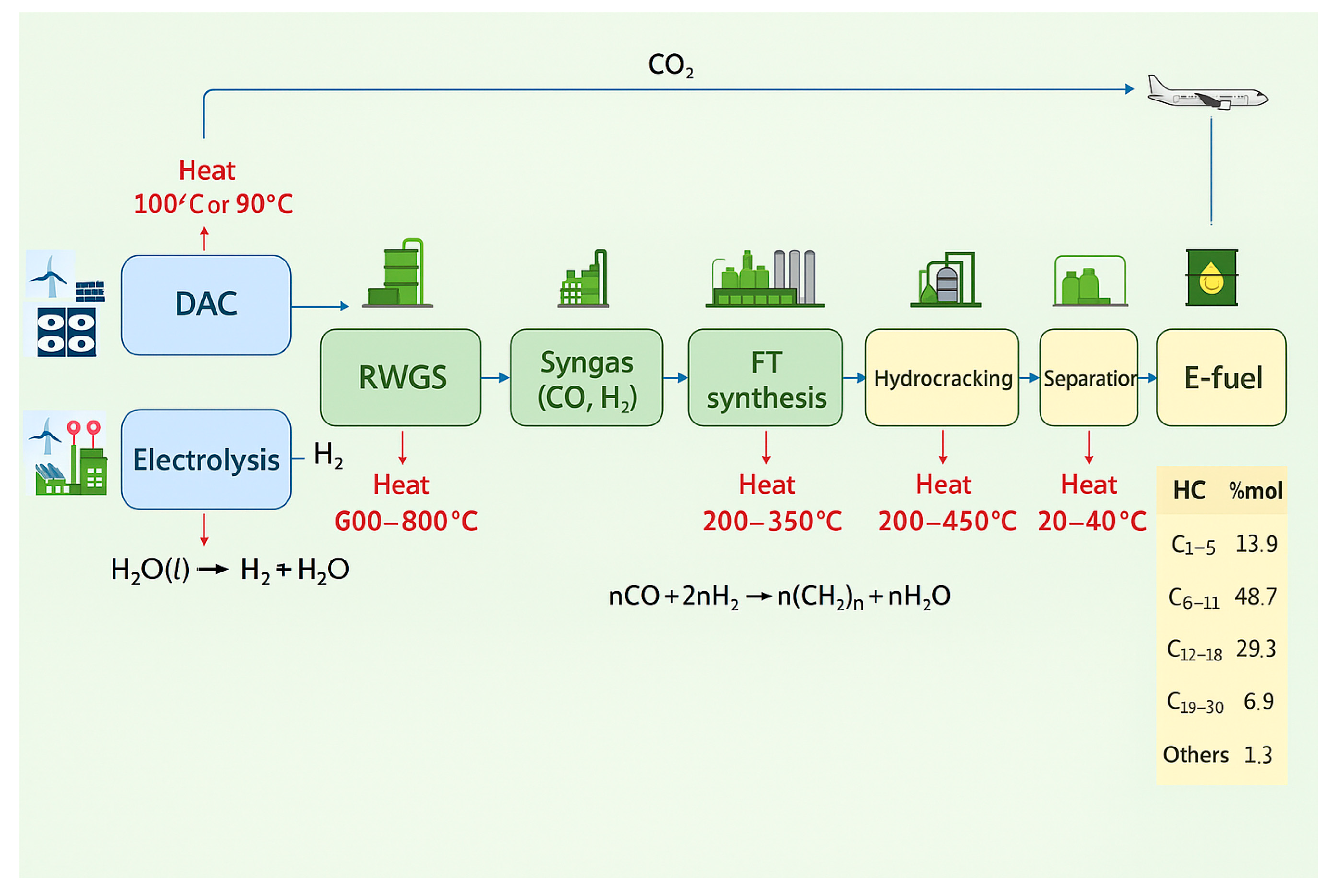
Different types of synthetic fuels (e-fuels) can be used to replace traditional jet fuel (Jet-A1) in gas turbine engines. The most promising e-fuel for gas turbines is SAF (Sustainable Aviation Fuel); they are made from renewable biomass or waste-based feedstock. SAFs are classified based on their carbon feedstock into hydroprocessed esters and fatty acid, Fischer–Tropsch synthetic paraffinic kerosene, alcohol-to-jet, and pyrolysis oil-to-jet. Since 2011, nearly 500,000 commercial flights have operated using e-fuel [
58]. The emission parameters show a significant reduction in SO
x emissions and PM compared to conventional kerosene [
57]. The number of UHC and CO also shows an overall downward trend. The number of nitrogen oxides is only minimally reduced. The production process of SAF is shown in
Figure 8.
The direct air capture (DAC) technology extracts CO
2 directly from the atmosphere to create aviation SAF, which forms a closed-loop system.
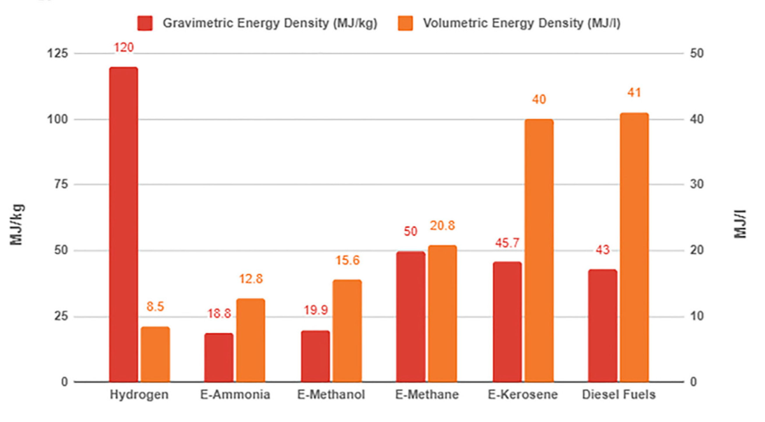
Figure 9. shows the volumetric and gravimetric energy density of different types of e-fuels [
60].
Compared to traditional fossil fuels, e-fuel is a more environmentally friendly alternative because it is produced using renewable energy sources such as wind, solar and hydroelectric power.
Table 3 summarizes the environmental impacts of alternative fuels from different sources [
61].
One of the key pillars of making aviation more sustainable is the use of Sustainable Aviation Fuel (SAF). According to a recent forecast by IATA, the global production of SAF will reach 2 million tons in 2025. Although this is double the amount produced the previous year, it still represents only 0.7% of the total fuel consumption of airlines. Despite this small share, it is expected to increase global fuel costs by $4.4 billion. The green transition comes at a significant price—one that passengers ultimately pay through higher ticket prices. Without coordinated efforts and state support, the cost could escalate further due to the limited availability of SAF on the market.
From 2025, the EU and the UK are implementing mandatory SAF blending requirements. While the intention behind these regulations is commendable, the lack of sufficient SAF supply has led to price surges in Europe, in part due to added compliance costs. As a result, SAF has become five times more expensive than conventional kerosene. IATA estimates that acquiring 1 million tons of SAF in 2024 would cost $1.2 billion, with an additional $1.7 billion in compliance-related expenses—resources that could otherwise reduce 3.5 million tons of CO2 emissions through alternative means. IATA warns that current EU regulations may actually hinder SAF adoption instead of encouraging it, placing unnecessary burdens on airlines.
As a global industry body, IATA proposes solutions. The organization has launched two initiatives to enhance transparency and efficiency in the SAF market: CADO (Council on Aviation and Decarbonization Oversight)—a global, transparent registry to track SAF purchases, usage, and related emission reductions, avoiding double-counting. The other initative is the SAF Matchmaker—a digital platform that connects airlines with SAF producers to better match supply and demand and prevent exclusive deals that could restrict market access and inflate prices.
While Europe grapples with high costs, India is making progress. With a population of 1.4 billion and now the fourth-largest civil aviation market, India has a vast base of agricultural waste and ethanol. The country aims to produce enough SAF not only for its own market but to become a net exporter as well.
Interestingly, India has also introduced SAF mandates for its airlines, but these are seen as more reasonable than those in the EU. Starting in 2027, India will require a 1% SAF blend for international flights, rising to 2% in 2028. The government is supporting this transition through price guarantees, capital investments, and supportive regulations.
SAF is indispensable for decarbonizing aviation, but given current production levels and cost structures, a rapid breakthrough is unlikely. IATA urges governments to redirect fossil fuel subsidies toward SAF, implement comprehensive energy strategies, and support the success of the CORSIA framework. India’s approach demonstrates that with the right feedstock, forward-thinking policies, and industrial collaboration, sustainable aviation can be more than just an environmental ideal—it can be an economically viable opportunity. The future of aviation is taking off in a new direction, though for now, the sector remains in a turbulent phase.
Rohkamp et al. analyzed gaseous and particulate matter emissions from a turboshaft engine running on HEFA-SAF blends. Their results demonstrated that 100% SAF reduced non-volatile particulate matter (nvPM) emissions by up to 81% and shifted particle sizes toward smaller diameters, resulting in up to 76% lower mass emissions compared to Jet A-1 [
62]. Durdina et al. confirmed similar findings using a small business jet engine. SAF use significantly reduced soot particle numbers and mass without compromising regulated emissions like NOx, CO, or UHC. Their study supports SAF’s effectiveness in improving local air quality and reducing contrail formation [
61]. Brodzik et al. reviewed fuel technologies and found that the environmental benefits of SAFs depend strongly on the raw materials and processing methods. For instance, HEFA from waste oils and fats results in much lower life-cycle emissions than conventional fuels. The authors also emphasized the role of hydrogen as a future zero-carbon option, though its current application is limited by infrastructure and technological readiness [
63].
5. Gaseous Fuels
Industrial gas turbines commonly operate on natural gas due to their high availability, clean combustion, and lower CO
2 emissions compared to liquid fuels. Natural gas-fired turbines are widely used in power plants, combined heat and power systems, and mechanical drives. However, the transition toward more sustainable energy sources has driven interest in alternative gaseous fuels. Hydrogen is a leading candidate because it produces zero-carbon emissions during combustion. Research shows that hydrogen can be used in gas turbines either in pure form or blended with natural gas. However, its high flame speed and low ignition energy raise challenges in combustion stability and NOx formation. To address this, researchers are developing advanced combustion techniques such as dry low NO
x (DLN) burners and lean-premixed systems. Other alternatives include syngas, produced from biomass or waste gasification, and biogas, derived from anaerobic digestion [
62]. These fuels vary in composition and heating value, requiring adaptive control systems and modified combustion hardware. Studies focus on combustion efficiency, emissions reduction, and turbine material resistance to impurities in these gases.
5.1. Hydrogen
As the lightest element, hydrogen exists as a diatomic gas (H2) under standard conditions and is characterized by a high energy content per unit mass (about 120 MJ/kg), though its volumetric energy density is low. Chemically, hydrogen is highly reactive and burns cleanly in the presence of oxygen, forming only water vapor as a byproduct, which makes it an attractive zero-carbon fuel. Its combustion involves fast radical chain reactions, often resulting in high flame speeds and broad flammability limits. These features make hydrogen suitable for stable combustion in lean premixed gas turbine systems. Advantages include its non-toxic nature, zero CO2 emissions, and potential production from renewable sources via electrolysis. However, challenges remain, such as NOₓ formation at high flame temperatures, storage difficulties due to low density, and material compatibility issues due to hydrogen embrittlement. Recent scientific and industrial research focuses on adapting turbine combustors to handle hydrogen blends or pure hydrogen, optimizing flame stability, reducing NOₓ emissions, and developing advanced storage and injection technologies. Companies like Siemens Energy and GE are already testing hydrogen-capable turbines, marking a critical step toward a hydrogen-powered future in aviation and power generation.
Using hydrogen as fuel releases minimal pollutants into the air. When combusted in an internal combustion heat engine, the main combustion product is water; no CO
2 is produced, and small amounts of NO
x compounds are produced [
64]. The environmental impact of hydrogen as a propellant is determined by the way it is produced. This distinguishes green hydrogen, which is produced from renewable energy sources such as solar or wind energy. The electrolysis method is used, where water is decomposed into hydrogen and oxygen by an electric current. The production of green hydrogen is environmentally friendly and sustainable as it does not emit carbon dioxide [
65].
There are basically three types of electrolyzers: alkaline electrolyzers, proton exchange membrane (PEM) electrolyzers, high temperature electrolyzers (HTE). The third type is sometimes called ‘solid oxide electrolyzers’ (SOE). Most of the electrolyzers currently used are alkaline (KOH) electrolyzers, as this is historically the earliest technology. PEM electrolyzers are even less widespread now, but they are showing dynamic development today. They actually correspond to the reverse operation of PEM fuel cells. High-temperature (HTE) electrolyzers represent the technology of the future, because in their case, basic research is still needed and they currently only exist on a laboratory scale. A common feature of electrolyzers is that to achieve the H2 production capacity, several “elementary” cells are connected, which together form a module, a so-called stack, similar to fuel cells. Thanks to the modular structure, it is theoretically possible to build larger systems by connecting several modules.
Gray hydrogen is the traditional method of producing hydrogen and the most common type of hydrogen used today, in which natural gas or other fossil fuels are reformed to produce hydrogen. This process emits significant amounts of carbon dioxide, which has a negative impact on the environment and climate change. Steam reforming produces hydrogen by reacting hydrocarbons with water vapor [
66].
The general form of the reaction equation:
Another method is partial oxidation (POX), in which hydrogen is produced by the partial oxidation of various hydrocarbons. The process involves the reaction of various hydrocarbons with oxygen at high temperatures:
In addition to gray and green hydrogen, the third method is blue hydrogen. Blue hydrogen is an intermediate solution between green and gray hydrogen [
67]. In the production of blue hydrogen, carbon dioxide is captured and stored, thus minimizing emissions. This method is more environmentally friendly than producing gray hydrogen, but it is not fully sustainable as fossil fuels are still used to produce hydrogen.
The combustion of hydrogen does not produce the typical hydrocarbon reaction intermediates, such as CO, and other more complex molecules, some of which are harmful and very reactive.
Valera-Medina et al. investigated ammonia–hydrogen and ammonia–methane blends in swirl-stabilized burners under gas turbine-relevant conditions. Their findings confirmed that stable combustion could be achieved, especially with hydrogen blends, although the flame behavior and NO
x emissions varied depending on the equivalence ratio and fuel composition [
68]. Nazari et al. provided a comprehensive review of hydrogen utilization in gas turbines, emphasizing its advantages such as high energy density and zero-carbon emissions. However, challenges include increased NOx emissions due to higher flame temperatures and flashback risks. They highlighted solutions such as fuel dilution with nitrogen or steam, exhaust gas recirculation, and advanced combustor designs to mitigate these issues [
67]. Meziane et al., Yoshimura et al. showed that even small additions of hydrogen to natural gas (e.g., 10%) can reduce CO and NOx emissions significantly while enhancing flame stability and system efficiency. Exergy analyses revealed that while hydrogen increases thermal performance, it may reduce exergy efficiency slightly and raise production costs, underlining the need for economic optimization [
69].
Nowadays, there are few gas turbine developments that are purely hydrogen powered. In CHP gas turbines, in traditional combustion chamber designs, 30% hydrogen can be mixed in the DLE combustion chamber in natural gas operation. For pure hydrogen combustion, the Multi Cluster Combustor combustion chamber design is currently being developed for the Mitsubishi H-25 gas turbine, which allows the combustion of ammonia in addition to hydrogen.
5.2. Methane
Methane (CH4) is the primary component of natural gas and a widely used fuel in gas turbine applications due to its availability, energy content, and clean-burning properties. It is a simple hydrocarbon with a high hydrogen-to-carbon ratio, resulting in relatively low CO2 emissions per unit of energy released. Physically, methane is a colorless, odorless gas at ambient conditions and requires compression or liquefaction for efficient storage and transport. Chemically, it is stable yet highly combustible, with a high autoignition temperature and narrow flammability limits. During combustion, methane primarily produces carbon dioxide and water, with minimal soot formation due to its molecular simplicity. Advantages of methane in turbines include high efficiency, established infrastructure, and lower pollutant emissions compared to heavier hydrocarbons. However, it is still a fossil fuel, contributing to greenhouse gas emissions, and methane leaks pose a significant environmental risk due to its high global warming potential. Current research efforts focus on increasing the efficiency of methane combustion, reducing NOₓ emissions through advanced lean premixed technologies, and blending methane with hydrogen or bio-methane. Industry leaders like General Electric and Mitsubishi Power are advancing methane-fueled turbine designs that aim to balance performance, emissions, and long-term sustainability in the transition to cleaner energy systems.
Methane (CH
4) is mainly used as an alternative fuel in compressed (200 bar) form known as Compressed Natural Gas (CNG). Another storage option is LNG (Liquefied Natural Gas), it should be stored at an operating pressure of 4–5 bar at −162 degrees Celsius. In both applications, the main constituents are low-carbon compounds of the methane and paraffinic hydrocarbon series, together with nitrogen, helium, carbon dioxide, sulfur compounds and mercury. Wet natural gas contains, in addition to methane, propane, butane, pentane and even higher-carbon hydrocarbons. Several studies have investigated the combustion of methane in gas turbine combustion chambers. O
2, CO
2, or N
2 have been added as oxidants for the combustion of methane. The studies have looked at different operating conditions and concluded that, in terms of emission parameters, it results in low nitrogen oxide emissions and higher CO emissions. Emissions are also affected by changing the oxidant composition. Several studies have investigated methane–ethane, methane-propane, and methane–hydrogen mixtures. In a methane–hydrogen mixture, hydrogen was found to reduce significantly the ignition delay time. The second observation is that the hydrogen addition did not seem to shift the dominant kinetic regimes for the range of mixtures. When testing methane–ethane mixtures, they found decreased ignition times but with similar activation energies as the CH
4-only mixtures. When testing methane-propane mixture the propane addition again speeds up the ignition process but with the same temperature dependence [
70].
The advantages of natural gas are that it is available in large quantities, is virtually sulfur-free, has very low particulate emissions (low C/H ratio), has negligible evaporation losses, and as a result of the low carbonyl/hydrogen ratio, the fuel produces less carbon dioxide per GJ of energy than kerosene or diesel, is flammable and therefore a leaner mixture will result in stable combustion, and is relatively cheap. Its disadvantages include being a fossil energy source, storage in compressed or liquefied form, and absorption of water vapor.
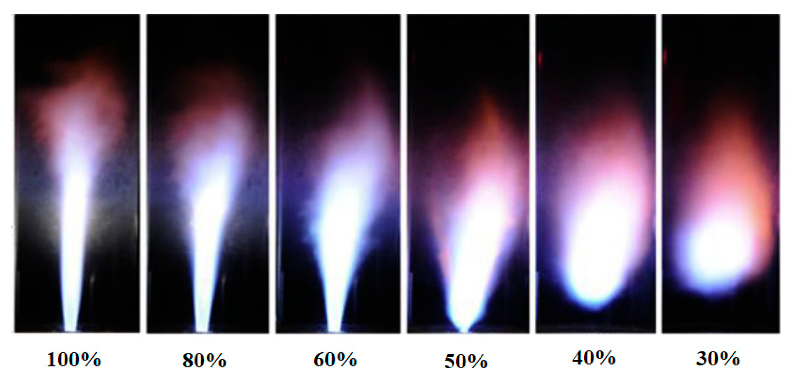
In many cases, low calorific value gases called inert gases have to be burned in gas turbines. In such cases, the carbon dioxide content of the oxidizing substances (oxygen, carbon dioxide) increases, resulting in a reduction in the flame length and stability in the combustion chamber [
71].
Figure 10 shows the decrease in oxygen content from left to right and the change in flame length and shape as the carbon dioxide component increases.
5.3. Propane-Butane Gas
Propane (C
3H
8) and butane (C
4H
10) are liquefied petroleum gases (LPGs) commonly used as alternative fuels in gas turbine systems. Both are hydrocarbons with high energy content and can be easily stored and transported in liquid form under moderate pressure. They exhibit clean-burning characteristics, producing mainly carbon dioxide and water during combustion, with low soot formation due to their relatively simple molecular structure. Their combustion involves chain reactions similar to other alkanes, with efficient energy release and stable flame behavior. Advantages include good availability, established infrastructure, and higher volumetric energy density compared to methane. However, they are fossil-based, contributing to CO
2 emissions, and may present challenges with cold-start operation and fuel–air mixing in turbines. Recent research focuses on optimizing LPG combustion for low-NOₓ emissions and improving turbine performance with variable LPG compositions. Industrial projects are exploring hybrid systems using LPG with hydrogen or biofuels to enhance sustainability in power generation [
72]. LPG is gaseous under normal atmospheric conditions, but liquefiable at low pressures (4–5 bar). Advantages include low sulfur content, capability of being stored in liquid form, negligible evaporation loss, negligible toxic components, and low particulate emissions. Disadvantages: low energy content per unit volume, heavier than air, high thermal expansion (container should not be filled to more than 80% of its full capacity) [
73].
5.4. Biogas
Biogas is a renewable fuel primarily composed of methane (CH
4) and carbon dioxide (CO
2), produced through the anaerobic digestion of organic matter such as agricultural waste, sewage, and food residues. Physically, it is a low-pressure gas with variable composition, typically containing 50–70% methane, making its energy content lower than that of pure natural gas. Chemically, the presence of CO
2 and trace impurities like hydrogen sulfide (H
2S) affects combustion characteristics and material compatibility. The combustion of biogas in gas turbines involves the oxidation of methane, releasing energy and producing CO
2 and H
2O, with combustion efficiency influenced by its methane concentration and impurities. Biogas offers advantages such as carbon neutrality, waste reduction, and local energy production. However, its variable composition, lower calorific value, and the need for gas cleaning present technical challenges in turbine systems. Biogas combustion can also lead to increased NOₓ emissions if not properly managed. Current research focuses on improving turbine combustion stability using biogas, upgrading biogas through CO
2 removal, and blending it with hydrogen or natural gas for enhanced performance. Industrial advancements include biogas-fueled microturbines and combined heat and power (CHP) systems, which are being implemented in agricultural and wastewater treatment facilities to promote sustainable energy generation [
39]. During biogas formation, simple sugars (e.g., glucose C
6H
12O
6) are formed from polysaccharides. Glucose is mainly converted into butyric acid, carbon dioxide and hydrogen:
The butyric acid forms acetic acid and methane, the resulting acetic acid forms methane and carbon dioxide, and the carbon dioxide and hydrogen form methane and water:
The gas produced is 60–70% methane, the rest is mostly CO2, with some hydrogen and hydrogen sulfide. Biogas has an energy content of 20–26 MJ/Nm3, depending on the methane content (methane has a calorific value of 35 MJ/Nm3). The energy content can be increased by removing carbon dioxide.
Several studies have investigated and compared the combustion of different gases in the combustion chamber of a gas turbine.
Table 4 below compares the physical and chemical properties of hydrogen, propane and methane with conventional Jet A1 kerosene [
74]
Valera-Medina et al. conducted experimental and numerical studies on the combustion of emulated biogas in a swirl burner under gas turbine-relevant conditions. Their results showed that stable combustion is achievable even with high CO
2 content (up to 60%), and emissions of CO and NO
x can remain below 10 ppm when normalized to 15% O
2. Importantly, thermal load variations did not significantly degrade combustion performance, demonstrating the flexibility of biogas in dynamic grid conditions [
75]. Rahman et al. performed validated 3D CFD simulations to compare biogas and natural gas combustion in a gas turbine combustor. Their findings indicated that, despite biogas’ lower LHV, proper tuning of swirl numbers and fuel injector diameters can yield combustion efficiencies and pattern factors comparable to natural gas. Biogas showed significantly lower NO emissions but higher CO emissions, suggesting that biogas is a viable alternative fuel if CO mitigation strategies are implemented [
76]. Lafay et al. experimentally investigated lean premixed biogas combustion in a gas turbine-like chamber using optical diagnostics. The flame behavior, structure, and instabilities were strongly influenced by laminar flame speed and fuel composition. CO
2 addition was found to decrease flame temperature and increase the likelihood of local extinction, leading to higher CO emissions. Hydrogen enrichment was shown to stabilize the flame and reduce CO, though at the cost of increased NO
x formation [
77].
Biogas, especially when optimized via hydrogen enrichment or flameless combustion, demonstrates strong potential as a renewable fuel for gas turbines. Its successful implementation depends on resolving challenges related to low LHV, emissions control, and flame stability. Advanced combustor designs, improved fuel injection strategies, and better emission mitigation techniques are key to unlocking the full potential of biogas in industrial CHP applications [
78].


