Article

Integrating Hydrogen into Power Systems: A Comprehensive Review

by
Javier Barba
1,
Miguel Cañas-Carretón
2,
Miguel Carrión
2,*,
Gabriel R. Hernández-Labrado
2,
Carlos Merino
3,
José Ignacio Muñoz
4 and
Rafael Zárate-Miñano
1
1
Escuela de Ingeniería Minera e Industrial de Almadén, Universidad de Castilla-La Mancha, 13400 Almadén, Spain
2
Escuela de Ingeniería Industrial y Aeroespacial de Toledo, Universidad de Castilla-La Mancha, 45071 Toledo, Spain
3
Centro Nacional del Hidrógeno, 13500 Puertollano, Spain
4
Escuela Técnica Superior de Ingeniería Industrial de Ciudad Real, Universidad de Castilla-La Mancha, 13001 Ciudad Real, Spain
*
Author to whom correspondence should be addressed.
Sustainability 2025, 17(13), 6117; https://doi.org/10.3390/su17136117
Submission received: 15 May 2025 / Revised: 13 June 2025 / Accepted: 28 June 2025 / Published: 3 July 2025
(This article belongs to the Special Issue The Role of Hydrogen in Future Renewable Power Systems)

Abstract

Hydrogen is widely recognized as a versatile energy carrier with significant potential to support the decarbonization of the power, transport, and industrial sectors. This paper analyzes the integration of hydrogen into power systems and offers an overview of the operation of electrolyzers and fuel cells for readers with limited background in these technologies. Applications of hydrogen beyond the scope of power systems are not considered. Then, this paper explores the mathematical modeling of hydrogen-related technologies, including electrolyzers and fuel cells, to assess their impact on hydrogen production and electricity generation. The paper also reviews recent developments in electricity storage through power-to-gas systems and examines planning models for integrating hydrogen into power systems. Furthermore, the role of hydrogen facilities in power system operations is analyzed in depth. The integration of hydrogen vehicles into power grids is also discussed, emphasizing their diverse applications. Additionally, the paper examines the production of ammonia, which can be used as a fuel for electricity generation. Finally, the most important conclusions of the literature review are summarized, offering an overview of the main findings and identified research gaps.

1. Introduction

The European Union is immersed in an ambitious plan to replace the use of fossil fuels with cleaner energy sources and achieve total decarbonization by the year 2050. Since the first decarbonization strategy, called Strategy 2020 [1], launched by the European Commission in 2010, to the Clean Energy for All Europeans strategy [2], adopted in 2019, the European Union’s commitment to drastically reduce the use of fossil fuels has been unequivocal. The goal of the Clean Energy for All Europeans strategy is to establish the necessary mechanisms to meet the greenhouse gas emission reduction targets set for the European Union that were defined in the Paris Agreement. In this regard, in May 2022, through the REPowerEU plan [3], the European Commission proposed the ambitious common goal of achieving 45% renewable energy regarding the total energy consumption of the European Union by the year 2030.
Explicitly, this plan highlights that hydrogen will be key to achieving the decarbonization goal set. Hydrogen is a gas that, until now, has been used for practical purposes to manufacture mainly ammonia, refine oil, and obtain steel. However, hydrogen is also a fuel that can be used to directly replace fossil fuels, for example in combustion engines and turbines, as well as being used in fuel cells to produce electricity. In this sense, the REPowerEU plan exclusively promotes the production of hydrogen through low-pollutant-emission procedures, preferably via electrolyzers electrically powered by wind and solar production. In this way, this plan encourages the installation of at least 6 GW of electrolyzers in the European Union between 2020 and 2024, and 40 GW from 2025 to 2030.
For its part, the United States has launched an incentive strategy called 45 V, which provides a significant economic stimulus for the generation of low-emission H 2 over a 10-year period from the date the facility is put into service. This incentive can reimburse up to USD 3/kg of hydrogen produced for projects with a greenhouse gas emission rate during their life cycle of less than 0.45 kgCO 2 e/kg H 2 (USC 45 V: credit for production of clean hydrogen (https://www.law.cornell.edu/uscode/text/26/45V) (accessed on 18 August 2024). This measure is in line with the U.S. National Clean Hydrogen Strategy and Roadmap (U.S. National Clean Hydrogen Strategy and Roadmap (https://www.hydrogen.energy.gov/library/roadmaps-vision/clean-hydrogen-strategy-roadmap) (accessed on 18 August 2024) that seeks the production of one trillion tons of H 2 by 2050.
In 2020, China announced its goal to achieve carbon neutrality by 2060, identifying hydrogen as a key player of this transition. The roadmap for achieving its 2030 green hydrogen targets is outlined in [4]. However, it should be emphasized that the promotion and growth of green hydrogen is not limited to Europe, the United States, and China as it reflects a global movement. For example, Morocco has approved USD 32.5 billion in green hydrogen projects; the Nigerian government is actively pursuing opportunities in the rapidly expanding global hydrogen economy, which is projected to exceed USD 200 billion by 2030; and Egypt has launched a national low-carbon hydrogen strategy aiming to capture 5–8% of the global tradable hydrogen market by 2040, alongside a cooperation agreement with France to develop green energy infrastructure [5,6]. Similarly, Australia released its National Hydrogen Strategy in September 2024, aiming to position the country as a global leader in renewable hydrogen, while New Zealand has set targets to incorporate 1.5 GW of electrolyzer capacity by 2035, increasing to 4.5 GW by 2050 [7]. Finally, Latin America and the Caribbean hold significant potential for low-emission hydrogen production thanks to their abundant renewable energy resources and decarbonized electricity mix. Countries such as Brazil, Chile, and Mexico have already announced green hydrogen initiatives that are beginning to move forward [8]. It is important to note that the reduction in hydrogen incentive programs could severely disrupt the development of the hydrogen economy. Given that low-emission hydrogen technologies are still in their early stages, a lack of financial support would lead to fewer hydrogen projects. This could stop the deployment of electrolyzers and slow technological progress. Furthermore, delays in hydrogen adoption would also hinder decarbonization in key sectors such as heavy industry and long-distance transport. Policy stability is crucial to maintaining investor confidence.
The use hydrogen holds great promise for the future decarbonization of the power, transport, and industrial sectors. However, the future role of hydrogen in the decarbonization of power systems is especially challenging and uncertain. Hydrogen can be burned in gas turbines, similar to natural gas, to generate power without producing CO 2 emissions, or be used in fuel cells to produce electricity. However, producing hydrogen presents challenges as it is usually generated by a non-clean process based on natural gas steam reforming. Natural gas reforming involves the reaction of methane ( CH 4 ), the primary component of natural gas, with steam ( H 2 O) to produce hydrogen ( H 2 ) and carbon monoxide (CO). This is conducted under high temperatures (700–1000 °C) and moderate pressure (3–25 bar). The chemical reaction is as follows:
C H 4 + H 2 O C O + 3 H 2
This reaction is endothermic, requiring a significant quantity of heat. The carbon monoxide produced in the previous process then undergoes the so-called water–gas shift reaction, where it reacts with additional steam to produce more hydrogen and carbon dioxide ( CO 2 ):
C O + H 2 O C O 2 + H 2
This reaction is exothermic, releasing heat. Note that this process emits CO 2 , necessitating the use of methods to prevent the release of this gas into the atmosphere, such as chemical absorption.
An alternative method for producing hydrogen without relying on fossil fuels is through electrolysis. Producing hydrogen via electrolyzers requires significant amounts of electricity. This electricity should come from green sources if hydrogen is to be produced by non-polluting methods. The generation of electricity through electrolyzers and its consumption in hydrogen turbines or fuel cells might be of interest in renewable energy-dominated systems. Excess renewable energy can be utilized to produce hydrogen, which can then be stored and later used to generate electricity during periods when renewable sources are not available. For example, Ref. [9] discusses recent advancements in hydrogen production, with a particular focus on green hydrogen generated using solar power. The key factors for the future development of hydrogen-based power plants include reducing the capital costs of electrolyzers and fuel cells, improving their efficiency and lifespan, and advancing economical hydrogen storage solutions.
It is also interesting to emphasize that the development of international hydrogen trade networks, whether via pipelines or chemical carriers such as liquid organic hydrogen carriers (LOHCs) or ammonia, has the potential to significantly reshape global energy geopolitics. Countries with abundant renewable resources, such as Spain, Chile, or Australia, may emerge as strategic exporters of green hydrogen, thereby enhancing their geopolitical relevance. This shift could reduce dependency on traditional fossil fuel exporters and redistribute global energy flows in a more decentralized manner [10].
Considering the impact that the planned incorporation of a large number of electrolyzers will have on electrical energy systems, and the increase in the availability of hydrogen, which could also be occasionally used for the production of electricity in gas turbines or fuel cells, there exist works aiming to develop decision-making models that allow for the planning and simultaneous operation of power and hydrogen systems, explicitly considering the relationships between both systems. It should be taken into account that hydrogen turbines could also be used to replace a certain number of natural gas turbines, thus maintaining the dispatchability of the electrical systems. In the same way, electrolyzers and fuel cells can be used to provide power reserves for adjustment services in electrical systems, enabling increases or decreases as needed. These two factors can help to increase the flexibility of the operation of electrical energy systems, which, in turn, will allow for an increase in the installed power of non-polluting intermittent technologies, such as wind and solar energy. In this way, greenhouse gas emissions will be reduced without compromising the operation and stability of the electrical system.
It is also worth highlighting that numerous projects related to H 2 are emerging globally, showing the increasing interest and investment in hydrogen technologies. First, one of the most outstanding projects is NorthH2, which was launched in 2020 to assess the technical and economic feasibility of large-scale green hydrogen production in the northern Netherlands, leveraging multi-stakeholder collaboration [11]. The initiative aims to integrate offshore wind-generated electricity with electrolysis to produce green hydrogen, which will subsequently be compressed, stored, and transported for industrial and heavy mobility applications across the Netherlands and neighboring markets. With its planned capacity and cross-sectoral scope, NortH2 ranks among Europe’s most strategically significant hydrogen ventures. Over a three-year research phase, the consortium—comprising RWE, Shell, Equinor, and Eneco—has validated the technical viability of gigawatt-scale hydrogen production in the region. The findings confirm the robustness of the proposed value chain, enabling the consortium to proceed with engineering and planning for the project’s next phase. Another notable large-scale project is the H2Go Energy Park Oude-Tonge [12]. This initiative seeks to repurpose Business Park Oostflakkee into a hub for producing renewable energy carriers, including green hydrogen, ammonia, and renewable gas. By localizing production, the project aims to enhance regional sustainability while creating synergies with nearby industries and infrastructure. Initially focused on constructing a pilot facility for hydrogen and renewable ammonia, the project has expanded into a comprehensive energy park development. Its strategic location offers direct access to potential hydrogen consumers. Finally, a list of 15 hydrogen projects, providing the following information for each—project name, status, technology, type of electricity, size, end use, and grid services—is presented in [13].
The successful deployment of hydrogen projects critically depends on the establishment of robust safety standards and coherent regulatory frameworks that ensure the safe production, storage, and distribution of hydrogen while fostering public trust and market scalability. Internationally, hydrogen safety is governed by technical standards developed by organizations such as the International Organization for Standardization (ISO) and the International Electrotechnical Commission (IEC). The ISO, a global non-governmental body, has issued standards like ISO 19880, which addresses the design and operation of hydrogen refueling stations, while the IEC has developed the IEC 62282 series, which outlines safety and performance requirements for fuel cell technologies [14,15]. In Europe, the Standardization Roadmap Hydrogen Technologies, coordinated by the German Federal Ministry for Economic Affairs and Climate Action, seeks to harmonize safety protocols across the hydrogen value chain by promoting pre-normative research, system interoperability, and unified certification systems [16]. Globally, regulatory frameworks are evolving to incorporate certification systems that define greenhouse gas thresholds for hydrogen production, aligning with the climate goals. The International Energy Agency has documented these developments, highlighting the diversity and complexity of the current regulatory approaches [8].
Government subsidies constitute essential instruments to overcome the economic barriers associated with green hydrogen production and to accelerate its integration into power systems. Recent evidence shows that, in the absence of carbon pricing mechanisms, the realization of global green hydrogen projects would require an estimated USD 1.3 trillion in subsidies. This magnitude of financial support underlines the urgent need for well-designed subsidy policies to make the transition towards green hydrogen economically feasible [17]. The Inflation Reduction Act (IRA) has set a global precedent with its tiered tax credits for hydrogen production based on carbon intensity. The 45 V credit offers up to USD 3 per kilogram of hydrogen depending on life cycle emissions, making hydrogen produced via electrolysis using carbon-free electricity and methane reforming with carbon capture and storage cost-competitive with carbon-intensive hydrogen [18]. However, IRA tax incentives alone are not sufficient to reach the cost target of USD 1 per kilogram of hydrogen for blue hydrogen, unless additional factors such as natural gas prices, inflation rates, and learning rates are taken into account [19]. In China, research shows that subsidies for hydrogen based on renewable electricity offer cost-effective CO2-equivalent reductions, while subsidies for grid-based hydrogen may increase greenhouse gas emissions in coal-dominated systems. Projections indicate that, by 2045 to 2050, off-grid water electrolysis systems could become the most cost-effective option for hydrogen production. This milestone could be brought forward within five to fifteen years through the implementation of targeted carbon reduction incentives or production subsidies [20].
The literature identifies three main types of carbon pricing mechanisms with specific applications to hydrogen integration within energy systems: carbon taxes, cap-and-trade systems, and hybrid approaches. A novel dynamic pricing mechanism for hydrogen, linked to the proportion of renewable energy in the power supply, could promote hydrogen production using renewable sources and minimize the operational costs in distributed power stations. Research shows that well-designed carbon pricing mechanisms can lead to significant emission reductions while stimulating innovation and investment in clean technologies [21]. The literature emphasizes the need for comprehensive strategies that integrate carbon pricing with broader economic and environmental policies. Research on low-carbon ammonia production demonstrates that economic feasibility requires policy frameworks including subsidies, carbon pricing, and renewable hydrogen regulations [22]. Also, the implementation of a carbon labeling system for hydrogen, such as the classification into green, blue, turquoise, or pink, may constitute a major component in attracting investment and enhancing market confidence. This classification enables stakeholders to clearly identify the origin and emission profile of hydrogen, thereby facilitating decisions aligned with decarbonization goals and reducing regulatory uncertainty. European initiatives like CertifHy represent important steps toward a unified guarantee-of-origin system [23].
Hydrogen price volatility is a concern for grid-connected installations as production costs are exposed to fluctuating electricity prices. In contrast, off-grid systems with dedicated renewables face less volatility. Power purchase agreements (PPAs) can mitigate this risk by offering long-term, stable electricity prices through bilateral contracts [24,25]. Additionally, the EU Innovation Fund [26] supports large-scale low-carbon technologies and off-grid renewable hydrogen projects, helping to reduce costs and exposure to market volatility, thereby contributing to more stable hydrogen pricing.
This paper provides an updated overview of the state-of-the-art integration of hydrogen in power systems. First, the paper details the mathematical modeling of hydrogen-related devices, including electrolyzers for hydrogen production from electricity and fuel cells for electricity generation using hydrogen. Next, the power-to-gas technology is described in detail. The paper then explores models for planning and operating systems that incorporate both hydrogen and power. The integration of hydrogen vehicles into power systems is also analyzed, as well as the production of ammonia. The structure of the paper is designed to highlight the central role of power systems in the context of hydrogen integration rather than to provide an exhaustive technical description of hydrogen technologies. Furthermore, numerical simulations and quantitative benchmarking are intentionally excluded as they fall beyond the intended scope of this review.

2. Technological Description and Mathematical Modeling of Electrolyzers and Fuel Cells

Electrolyzers and fuel cells are static energy conversion devices in which an energy transformation from electricity to chemical energy, or vice versa, takes place. While electrolyzers use electricity to produce hydrogen, in fuel cells, the energy conversion follows the opposite path; i.e., hydrogen as fuel is used to generate electricity.
In recent years, electrolyzer technologies have seen significant advancements, improving efficiency, reducing costs, and increasing their commercial viability. Currently, the commercially available electrolyzers consist of alkaline electrolyzers (AEs), proton exchange membrane electrolyzers (PEMs), and solid oxide electrolyzers (SOEs), which are still in the research and development phase. AE systems have been widely used for decades and are known for their durability and cost-effectiveness. They operate at moderate temperatures (60–80 °C) and pressures and at lower efficiencies than PEM electrolyzers, typically achieving 60–70% efficiency in terms of hydrogen production. AE systems are best suited for large-scale operations but struggle with rapid response times needed for integration with intermittent renewable energy sources [27,28]. On the other hand, PEM electrolyzers operate at moderate temperatures (50–80 °C) and at higher pressures (up to 30 bar). They also offer higher efficiencies than AE systems (up to 80%) and are more flexible in terms of responding to dynamic renewable energy generation. However, they are more expensive due to the need for precious metal catalysts like platinum and iridium. Recent advances in catalyst research are focused on reducing the costs of PEM systems while maintaining or enhancing their efficiency [29]. The scalability of PEM technologies is currently constrained by their reliance on platinum-group metals, such as platinum and iridium, for electrode functionality. Nevertheless, recent research has explored alternative catalysts based on nickel, cobalt, mixed oxides, and nitrogen-doped materials, showing promising results in terms of performance and cost-effectiveness [30]. With sustained investment in R&D, these alternatives could become commercially viable by 2035. SOE systems operate at high temperatures and are typically coupled with high-temperature heat sources, such as concentrated solar power, to improve efficiency (up to 90%), which allows them to take advantage of waste heat from industrial processes or power plants. Therefore, SOEs offer the highest efficiency compared to AE and PEM electrolyzers as the high operating temperatures help to reduce the energy needed for the electrolysis process. At the same time, the primary limitation of SOEs is the high operating temperature, which requires significant insulation and specialized materials that are highly durable [31]. Additionally, these systems have slower startup times, making them less suitable for rapid load-following applications [32]. The yield of electrolyzers is a key factor in determining their viability for green hydrogen production. Several factors affect the efficiency of electrolysis, including the type of electrolyte, the electrode material, and the operating temperature. For example, PEM electrolyzers, while more efficient, require sophisticated materials that are currently expensive to manufacture at scale. Recent research has focused on improving these systems through innovations in catalyst design, such as using non-precious metals or advanced composite materials to reduce costs [33]. Another underexplored but important issue is the environmental impact associated with the disposal or recycling of catalysts containing precious metals at the end of the system’s life. Given the current limited commercial deployment of PEM systems, there is no widespread infrastructure for efficient catalyst recycling [34]. Life cycle assessments (LCAs) reveal significant differences in the carbon footprint of electrolysis technologies. AE shows a wide emission range (1– 30 kgCO 2 eq/kgH 2 ), while SOE exhibits lower and more stable values (0– 5 kgCO 2 eq/kgH 2 ). PEM presents similar variability to AE (0.5– 30 kgCO 2 eq/kgH 2 ). When powered by renewables, AE emissions drop to 1.19– 4.45 kgCO 2 eq/kgH 2 , and SOE with nuclear energy achieves as low as 0.416 kgCO 2 eq/kgH 2 . SOE stands out for its low average footprint due to high thermal efficiency and compatibility with low-carbon energy. In contrast, AE and PEM are highly dependent on electricity sources: under fossil-based grids, emissions exceed 20 kgCO 2 eq/kgH 2 , but, with renewables, they fall near 2 kg [35].
Electrolyzer technologies can be categorized into four different types. These categories mainly depend on the material of their electrodes, the specific reaction taking place both at the anode and the cathode, and the electrolyte through which ions are transported. These devices are the aforementioned AEs, PEMs, and SOEs, together with the anion exchange membrane electrolyzer (AEME) [36]. On the other hand, fuel cell stacks can be distinguished into proton exchange membrane fuel cells (PEMFCs), direct methanol fuel cells (DMFCs), solid oxide fuel cells (SOFCs), phosphoric acid fuel cells (PAFCs), alkaline fuel cells (AFCs), and molten carbonate fuel cells (MCFCs) [37,38]. Table 1 shows the main characteristics of the electrolyzer and fuel cell technologies mentioned above.
In broad terms, both types of devices (electrolyzers and fuel cells) are basically composed of a cathode, an anode, and an electrolyte, with the reduction reaction taking place at the cathode and the oxidation at the anode. In general, in the overall reaction that happens in an electrolyzer, water is split into oxygen and hydrogen, as shown in Equation (3), whereas, in a typical fuel cell, oxygen and hydrogen combine to produce water and energy (Equation (4)). More complex reactions can be hidden in the generation of the products.
H 2 O + energy H 2 + O 2
H 2 + O 2 H 2 O + energy
Mathematical modeling of electrolyzers and fuel cells has become crucial in the development and optimization of these technologies for their application within sustainable energy systems. For electrolyzers, theoretical, semi-empirical, and empirical models typically focus on predicting the hydrogen production rates and the efficiency of the device [39], as well as physical phenomena like electrochemical and thermal processes [40]. On the other hand, modeling of fuel cells mainly focuses on optimizing the amount of heat and electrical energy that the stacks may produce [38].
Both electrolyzer and fuel cell models have benefited from recent advances in computational techniques, allowing for more accurate and computationally efficient simulations. These models have been instrumental in guiding the design of new materials, optimizing operating strategies, and scaling up systems for commercial applications. They also include mechanistic approaches, providing detailed equations for understanding stack mechanisms and efficiency, and semi-empirical models that require continuous feedback from actual electrolyzer and fuel cell operations.
This modeling not only helps to reduce research time and costs but also enables the analysis and prediction of parameters such as temperature, pressure, or electrical magnitudes, among others, which can affect their efficiency and development [41]. These mathematical models provide valuable insights into a wide variety of complex physical processes, such as heat and mass transfer phenomena, electrochemical processes, or thermodynamical and thermal effects. All this modeling is established with a view to being used in other more specific applications, such as hydrogen production or power generation within electricity markets.
Next, the electrochemical modeling of electrolyzers and fuel cells is presented, followed by an overview of the latest advances in electrocatalyst materials and low-energy anodic reactions, as well as the formulation of applied models used in power system planning and operation. The thermal and mass transport and consumption/production of species models for electrolyzers and fuel cells are described in Appendix A.

2.1. Electrochemical Model

Electrochemical processes in electrolyzers and fuel cells could be described in a similar way. Several studies have focused on dynamic modeling to enhance accuracy, efficiency, and reliability, although it is also common to use steady-state modeling, mainly for PEM and AE in terms of electrolyzers. The electrochemical behavior of both types of devices can be modeled by means of the use of the polarization curve, also called I–V characteristic. This polarization curve represents the performance of the cell voltage as a function of the current density crossing the cell.
In electrolyzers, the operating cell voltage V cell , el can be obtained as the sum of different contributions. As shown in Equation (5), these terms are the reversible voltage V rev , the activation overpotentials at the anode V act , a and the cathode V act , c , the ohmic voltage drop V ohm , and the diffusion overpotential V diff [36]. In some studies [42,43,44], the whole Equation (5) is considered for their theoretical and experimental modeling. However, in other works, the diffusion voltage drop has been neglected and another simplified equation has been taken into account [45]. For fuel cells, the cell potential is given as the subtraction of the reversible voltage minus the different voltage drops and overpotentials [46]. The total potential of a stack, both in electrolyzers and fuel cells, could be obtained by multiplying the number of cells in the stack by the voltage of a single cell.
V cell , el = V rev + V act , a + V act , c + V ohm + V diff
Reversible potential V rev , also called open-circuit potential, represents the minimum electrical energy needed to cause the reaction in a reversible electrochemical process. In the case of electrolyzers, it refers to the minimum energy required to split water molecules, and, in the case of fuel cells, the minimum energy to combine the hydrogen and oxygen molecules. This magnitude can be obtained from the change in the Gibbs free energy ( Δ G ), as shown in Equation (6), where z is the amount of charge transferred in the reaction to produce 1 mol of hydrogen (in this case, z = 2 ) and F is the Faraday constant, 96,485 C/mol. On the other hand, the reversible potential can also be derived from the Nernst equation for water electrolysis in electrolyzers [36] or hydrogen oxidation in fuel cells [47], following an empirical and strongly temperature-dependent relationship at atmospheric pressure [48,49,50]. The open-circuit potential differs from the thermoneutral cell voltage V th , which is related to the total amount of energy needed to produce the electrolysis of water and which is associated with a change in enthalpy ( Δ H ), as shown in Equation (7) [40], and is also strongly affected by temperature [51]:
V rev = Δ G z F
V th = Δ H z F
Activation overpotentials V act , a and V act , c are related to the energy involved in the charge transfer processes from the reactants to the electrodes, which initiate the reaction at both locations. This magnitude is usually higher at the anode than at the cathode [51] and strongly depends on the electrocatalyst activity, the morphology of the electrode material, as well as the pressure and temperature of the device, among other factors [49]. Activation overpotential on each electrode can be derived from the Butler–Volmer equation [52], obtaining Equation (8), although a more simplified expression for this magnitude (Equation (9)) can be obtained when a high current density is considered [36]. In these formulas, R represents the gas constant, T the temperature, α k the charge transfer coefficient at the anode or cathode, i k and i 0 , k the current density and exchange current density at each electrode, and k each one of both electrodes (anode or cathode).
V act , k = R T α k F sinh 1 i k 2 i 0 , k
V act , k = R T α k z F ln i k i 0 , k
Ohmic voltage drop V ohm is related to ohmic losses inside the device, which are produced by both electronic and ionic effects. These losses can be expressed from Ohm’s law as the sum of different potential drops related to each element of the device. These voltage drops are proportional to the electric current I flowing through the electrolyzer or fuel cell and the equivalent electrical resistance of each element. The electrical resistances considered are similar for all models, although they slightly depend on the elements that comprise each device.
For instance, in an AE, the ohmic resistance includes the electrode resistance (i.e., anode R an and cathode R cat ), the electrolyte resistance R elec , and the diaphragm resistance R dia (Equation (10)) [36]. However, in a PEM, the diaphragm resistance in Equation (10) is replaced by the electrolyzer membrane resistance R mem , and the plate resistance can also be included [49]. Each of these parameters can be described based on the electrical conductivity or resistivity of the materials they are composed of, as well as their physical dimensions, such as thickness and area [53].
Moreover, some studies consider only the membrane and electrolyte resistances [54], whereas other models also include the resistance of the bubbles produced within the device or the contact resistance of the electrodes. Generally, R dia is the main cause of the ohmic voltage drop in AEs [36], whereas R mem is the dominant resistance in PEMs [43].
V ohm = ( R an + R cat + R elec + R dia ) I
Diffusion overpotential V diff , also called concentration overpotential [36] or gas propagation voltage drop [43], refers to the energy lost during the mass transport processes throughout the device. This voltage drop is caused by the movement of products and the supply of reactants near the electrodes or throughout the existing media in the core of the device, directly affecting the flow of electrical current through the electrolyzer or fuel cell. As mass flows through a porous media such as in a PEM [42], or simply the flow of species caused by concentration gradients [52], the transport phenomena can mainly be described by means of equations derived from Fick’s laws [53]. However, diffusion overpotentials at the anode and cathode can also be estimated by applying the Nernst equation in the vicinity of each electrode and expressed from the concentration of species, obtaining Equations (11) and (12) [53,55,56]:
V diff , an = R T 4 F ln C O 2 C O 2 , 0
V diff , cat = R T 2 F ln C H 2 C H 2 , 0
In Equations (11) and (12), C O 2 and C H 2 represent the respective molar concentrations of oxygen and hydrogen at the electrode–electrolyte interface of the anode and cathode, whereas C O 2 , 0 and C H 2 , 0 are the concentrations of each species close to the electrodes under reference working conditions. Another derived expression for describing diffusion overpotential, which has also been used to model both PEM [43] and PEMFC [57], is shown in Equation (13), in which concentration overpotential is directly related to the operating current density of the device and the maximum current density that can be provided and is limited by diffusion i lim . Nevertheless, taking into account the current densities operating inside the electrolyzers and fuel cells, this voltage drop is usually neglected [58].
V diff = R T z F ln 1 + i i lim
For the sake of simplicity, empirical and semi-empirical models have been developed to represent the electrochemical performance of the devices, particularly the behavior inside the electrolyzers. These models describe the cell voltage as a function of a reduced number of parameters, and some of them have been applied in practical situations. In [59], a simple expression for cell voltage has been implemented, which only depends on the current density i and parameters A 1 and A 2 reliant on the temperature. This relationship is shown in Equation (14). Similarly to this model, in [40], a more detailed polarization curve model has been developed, which takes into account the temperature dependence of the different ohmic resistance parameters r i and other coefficients related to activation overpotentials, such as s and t i . This model is shown in Equation (15), where A represents the area of the electrode. On the basis of the scheme proposed in [40,60], a new model is presented, including additional variables such as the distance between electrodes and the electrolyte concentrations. In this last work, the influence of different operating parameters for hydrogen production in the electrochemical modeling of an AW was studied. Moreover, from the model proposed in [60] and by adding new parameters depending on the pressure, the performance of a 15 kW AW was validated [61], and a new model for an alkaline electrolysis plant has also been proposed [62].
V cell , el = V rev + A 1 i + A 2 log ( i )
V cell , el = V rev + ( r 1 + r 2 T ) A i + s log t 1 + t 2 / T + t 3 / T 2 A i + 1
On the other hand, simplified empirical and semi-empirical descriptions for I–V curves in fuel cells can also be found in the literature. In [63], a simple relationship to describe the evolution of cell voltage as a function of current density for a PEMFC, which has been derived from the Tafel equation, is shown by means of Equation (16). In this expression, V cell , fc is the cell voltage of the fuel cell, i 0 represents the exchange current density at the reference concentration, parameter b is the Tafel slope for oxygen reduction, and R is the ohmic resistance of the polymer electrolyte. Slight variations of the model proposed in [63] can be found in [64,65] by adding new terms related to the mass transport overpotential and cell pressure, which have been used to validate the electrochemical behavior of DMFCs. Similarly to those works, Equation (17) represents the model proposed in [66] for the cell voltage of PEFCs, in which a new term added on the right side is interpreted as an additional voltage drop due to mass transport limitation, and where α , β , and γ are parameters to be fitted. A similar expression to Equation (17) was also proposed in [67], and a slightly more complex interpretation including new parameters and constants in [68].
V cell , fc = V rev + b log ( i 0 ) b log ( i ) R i
V cell , fc = V rev + b log ( i 0 ) b log ( i ) R i + α i γ ln ( 1 + β i )

2.2. Description of Latest Advances in Electrocatalyst Materials and Lower-Energy Anodic Reactions

Materials involved in electrocatalyst processes play a central role in the development, optimization, and evolution of both electrolyzers and fuel cells as viable technologies for clean energy production. Both kinds of devices rely on electrocatalysis to accelerate sluggish interfacial reactions at the electrodes, particularly the hydrogen evolution reaction (HER) and oxygen evolution reaction (OER). Research in this area has been largely driven for years by the need to improve the catalytic activity, durability, efficiency, and cost-effectiveness of devices, especially in the context of HER and OER for electrolyzers, and oxygen reduction reaction (ORR) in fuel cells. In [69,70], the main technical requirements for good electrocatalyst systems are summarized, including good electrocatalytic properties of materials, resistance to mechanical and electrical wear, high electrical conductivity, and good stability under open-circuit conditions, among other properties. Other key performance indicators related to catalytic performance, like selectivity or availability, are detailed in [71].
Durability and stability have been recurring issues of concern in most electrocatalyst families of materials. Carbon corrosion, dissolution of active metals, agglomeration of nanoparticles, and restructuring under operating conditions often lead to performance degradation of electrocatalysts over time. Several materials, as well as strategies for the improvement of their properties, such as core–shell architectures, heterostructures, and surface passivation, have been studied and developed to mitigate these negative effects. Additionally, the development of in situ operation and characterization techniques enhances the mechanistic understanding of degradation pathways, guiding the rational design of more robust and reliable catalysts.
Precious and noble metals like platinum (Pt), iridium (Ir), ruthenium (Ru), and their oxides (for instance, IrO2 or RuO2) have dominated this field due to their excellent catalytic activity and stability under harsh electrochemical conditions [72]. However, their scarcity, low scalability, high cost, and poor durability have limited their practical applications [73]. To mitigate these drawbacks, transition metal-based materials have also been explored as promising catalyst substitutes, including oxides, hydroxides, sulfides, phosphides, and nitrides of nickel (Ni), cobalt (Co), iron (Fe), and molybdenum (Mo). For instance, NiFe has been studied for its application in OERs taking place in alkaline media [74], and MoS2-based materials as catalysts in HERs by splitting water [75]. Bimetallic and trimetallic alloys such as Pt-Co, Pt-Ni, and Pt-Ni-Fe have also been investigated as alternatives to catalytic materials used, among others, in PEMFCs [76,77]. Carbon-based materials, such as nitrogen-doped graphene or carbon nanotubes, have also gained interest and been considered as both supports and active sites in catalysis for hydrogen water electrolysis due to their exceptional properties, such as thermal stability, improved electrical conductivity, and surface resistance to both acidic and basic media, among others [78].
The latest breakthroughs in water electrolysis catalysis have focused on improving activity and stability through advanced material design. One prominent strategy is forming protective heterostructures that shield the active sites of materials from harsh conditions. For example, in [79], a Pt-Ni3N catalyst coated with a thin V2O3 layer was proposed, which acts like “armor” to protect the electrodes from chloride and impurities during alkaline seawater electrolysis. This protection enabled the achievement of industrial-level current densities (1 A/cm2) with sustained and stable hydrogen production for 500 h, minimizing corrosion and extending catalyst lifetime. Another impactful improvement relates to the design of nanostructured alloy catalysts on conductive supports to maximize active surface area and synergistic effects. In [80], a core–shell nanoreactor consisting of Ni-Fe alloy nanoparticles confined within graphene layers was proposed. This catalyst leverages the high conductivity and chemical stability of graphene to enhance the Ni–Fe active sites. In alkaline water electrolysis, this alloy required only between 1.50 and 1.60 V to achieve current densities between 10 and 100 mA/cm2, maintaining remarkable stability over 1000 h of continuous operation. These results highlight that integrating bimetallic catalysts with carbon-based scaffolds improves both performance and durability.
Similarly, other structures based on porous and high-surface-area architectures have also shown great promise. In [81], a self-limited synthesis of nanoporous Ni heterostructures is reported, yielding a highly accessible network of active sites. The resulting electrode exhibited enhanced hydrogen evolution kinetics comparable to precious and noble metals, attributed to its large electrochemical surface area and efficient mass transport pathways.
In order to reduce the use of precious metals, some researchers have explored atom-efficient catalyst designs and robust earth-abundant materials. For instance, in [82], ultrafine noble metal nanoclusters dispersed on transition-metal oxides were proposed. In this work, the authors demonstrated that incorporating CoOx oxides with ruthenium (Ru) produces an OER electrocatalyst with improved intrinsic activity and stability. This Co–Ru composite achieves high oxygen evolution rates in alkaline media.
On the other hand, in acidic environments, it was demonstrated in [83] that a cobalt phosphate hydrate catalyst supported on carbon nanofibers approaches the acidic HER performance of Pt, operating stably for 24 h at 10 mA/cm2 without significant activity loss.
Finally, in a recent work [84], a tungsten sulfide catalyst with an unconventional coordination environment was reported. A tetra-coordinated W2S3 catalyst was synthesized and proved to be effectively active for HERs across both acidic and alkaline electrolytes. The atomic structure and electronic properties of this material conferred it with excellent dual-pH hydrogen evolution activity and corrosion resistance, addressing the challenge of catalyst versatility.
Ongoing research is expected to build on these advances, focusing on increasing catalyst longevity, reducing reliance on critical metals, and understanding degradation mechanisms to inform next-generation catalyst designs.
Replacing the conventional OER with alternative low-energy anodic reactions has emerged as a compelling approach to reduce the energy consumption of electrolytic hydrogen production. In water electrolysis, the OER at the anode is thermodynamically demanding, with a standard potential of 1.23 V. By contrast, oxidizing certain compounds or waste molecules at the anode allows reactions to occur at much lower potentials while co-producing value-added or benign products.
For instance, the urea oxidation reaction (UOR) has a theoretical potential of only 0.37 V vs. the reversible hydrogen electrode (RHE) owing to the favorable decomposition of urea into N2 and CO2. In [85], the authors highlighted that complete urea electrolysis can deliver hydrogen at a cell voltage roughly 0.15–0.20 V lower than pure water electrolysis with an appropriate UOR catalyst, reaching 100 mA/cm2 at 1.51 V using urea as the anodic fuel. Similarly, ammonia oxidation to N2 (in alkaline media) is even more energetically favorable, with a thermodynamic requirement close to 0 V, while methanol and glycerol oxidations proceed around 0.0–0.1 V. In [86], the authors reported that, during the ammonia oxidation reaction (AOR), it is possible to drive H2 production at cell voltages below 0.7 V, representing more than a 50% reduction in voltage compared to conventional water electrolysis. Exploiting one of these reactions (UOR or AOR) in a so-called “hybrid electrolyzer” drastically reduces the cell voltage for hydrogen generation. In practical terms, switching from OER to UOR can decrease the anodic overpotential by 0.5 to 0.8 V, translating to substantial energy savings [87]. Nevertheless, some authors also highlight the influence of the catalyst used in the device on the cell voltage obtained [88,89]. Moreover, these alternative anodic processes simultaneously address environmental and economic goals. For instance, urea and ammonia electrolysis can remediate water pollution by converting waste into N2, while oxidizing biomass-derived alcohols (e.g., methanol, ethanol, propanol, or glycerol) yields valuable chemicals like formate or formic acid as co-products [86]. This dual benefit—hydrogen production with waste valorization—makes low-energy anodic reactions highly attractive for sustainable hydrogen systems.
In summary, low-energy anodic reactions such as UOR, AOR, and alcohol oxidations represent a transformative approach to boost the efficiency of hydrogen electrolysis by substituting the OER with more energetically favorable oxidation reactions. This enables future hydrogen generators to operate at much higher efficiency while simultaneously converting waste streams into useful outputs. Despite the clear thermodynamic and environmental benefits, these alternative anodic reactions introduce new research challenges, such as slower reaction kinetics and catalyst stability. This approach aligns perfectly with circular economy principles and could greatly enhance the sustainability of hydrogen energy systems.

2.3. Applied Models for Electrolyzers and Fuel Cells in Power System Planning and Economic Dispatch

The integration of hydrogen technologies, such as electrolyzers and fuel cells, in power systems is gaining more and more interest in the study of electricity systems and market planning. Although these models are mainly focused on economic issues, some magnitudes and technical features, such as power limits, operation states, device efficiencies, or production/consumption fuel rates, are also considered.
In [90], a mathematical model for a dynamic economic dispatch of a microgrid is proposed, in which a fuel cell is included. The fuel cell is modeled by means of the gas consumption cost, which depends on the output power during the period of calculation, the efficiency of the fuel cell, the net thermal value of gas, and the price of gas. In [91], a techno-economic assessment of a hybrid system consisting of wind, photovoltaic, and hydrogen energies, including fuel cells and electrolyzers with a reverse osmosis desalination system, was proposed. To model both the fuel cells and the electrolyzers, the authors used as the only variable the amount of hydrogen stored in the hydrogen tanks, produced by the electrolyzers and consumed by the fuel cells. This magnitude depends on the efficiency of the devices involved and is limited by both minimum and maximum values of capacity. Moreover, to optimize costs, this work also considers the capital and the annual maintenance costs of both devices.
An AC-linked hybrid wind/photovoltaic system including a fuel cell and electrolyzer combination as a backup and a long-term storage system was studied in an incipient work about applied electrolyzer modeling [92]. In this work, the mathematical model of the electrolyzer refers to the cell potential described by Equation (17), whereas the references to both electrolyzers and fuel cells in the proposed model are related to the inclusion in the power balance equation as the electric power consumed by the electrolyzer and the power generated by the fuel cell. In [93], a techno-economic model involving a large-scale multi-MW installed electrolysis plant was proposed. This model was applied in a case study to provide grid services and determine the minimum demand required from a fuel cell electric vehicle market. In this work, an optimal economic dispatch of an electrolysis plant was explored in which the aim was to maximize the economic benefits. Related to the electrolyzer model, in addition to the incomes and costs, three variables were calculated and used to maximize the benefits. One of them is the load factor of the electrolyzer r h , which represents the percentage of power demand related to the nominal power. The other variables are binary variables related to the operation states of the electrolyzer considered in this work, which are production, referring to the state in which the device produces hydrogen when the input power is applied, and standby, in which no hydrogen production is generated but electricity consumption is required by the electrolyzer to maintain specific temperature and pressure conditions within the device. These authors increased the number of operational states for the electrolyzer in a later work [94], including the new state (idle), in which the electrolyzer is turned off and only low power consumption for control units and anti-freezing systems is required. This new state was also modeled with an additional binary variable. To maximize the benefits, this last model also considers the costs related to the transition between the idle and production states (cold start time) and the standby to production (hot start time). On the other hand, the revenues are related to the hydrogen sold during the production state of the electrolyzer R h , depending, as shown in Equation (18), on the rated power P, the remuneration for the hydrogen sold R H , the load factor of the device r h , and its efficiency η in kWh/kg. Similarities with the three-state model proposed in this study can also be observed in [95]. The three-state model was also considered in [96], where two additional binary variables were included to compute the startup and shutdown cycles of the electrolyzer, and one only binary variable to represent the transition from standby to production state. Considered constraints in this work related to electrolyzer modeling include capacity, hydrogen production, and ramp-up and ramp-down rate constraints.
R h = R H P η r h
In [97], an optimal operation problem of an energy hub including a hydrogen production plant and fuel cell was studied. In this work, references to the electrolyzer and fuel cell were considered in terms of power and efficiency within the power balance equation, as well as binary variables to define power flows into or out of the devices. A model proposed to couple the power-to-heat and power-to-hydrogen processes in an electrolyzer was also studied [98]. The authors defined the technical characteristics of the electrolyzer from the electrochemical and heat transfer processes and equations defined above, mainly considering the relationship between the electric energy consumed by the electrolyzer and the power converted to heat and hydrogen energy for the proposed model. These magnitudes are related by means of the efficiency of hydrogen generation η t n , defined in this study as shown in Equation (19).
η t n = V t h V c e l l , e l
A techno-economic analysis of a system based on wind energy, hydrogen producers, and fuel cell vehicles was presented in [99]. The reference to the electrolyzer in this economic model was included in terms of the annual revenue from the sale of hydrogen, provided as the product of the market price of hydrogen and the annual production of the electrolyzer. Equation (20) was used by these authors to quantify the hydrogen production Q H 2 , e l , which is derived from Equation (A15) (included in Appendix A) and written in terms of hydrogen production power P e l and the voltage of the device V e l . Other expressions for hydrogen production derived from Faraday’s law and based on the lower heating value of hydrogen have also been used in other economic studies on power systems and microgrids to describe hydrogen production from electrolyzers [100,101]. Similar expressions were also used to model electrolyzers and fuel cells for hydrogen production and consumption in [86,102]. More detailed expressions of hydrogen generation by electrolyzers depending on the operation temperature of the cells can be found in [103]. This last research work focused on the optimization of electrolyzers and fuel cells capacity, including in wind/photovoltaic coupled hydrogen energy grid-connected systems. Moreover, to describe the hydrogen consumption rate Q H 2 , f c in the fuel cells, Equation (21) has frequently been used, where n c , f c is the number of fuel cells, P f c is the power provided by the fuel cell, and V f c is the stack voltage. For the sake of the economic analysis, the authors also took into account capacity constraints in terms of power of both electrolyzers and fuel cells, as also considered in [104].
Q H 2 , e l = η F n c , e l P e l z F V e l
Q H 2 , f c = n c , f c P f c z F V f c
In [105], a mathematical model of a renewable power plant coupled with a battery storage and a hydrogen facility for trading in energy markets of electricity, natural gas, and hydrogen was proposed. Related to hydrogen facilities, an operational scheduling for simultaneous use of an electrolyzer and a fuel cell was covered. Electrolyzer and fuel cell constraints considered in this work are related to the reserve provision and the operation power of the devices, which is limited between a minimum and a maximum value. These constraints were also used in [106] to model the electrolyzer stack. The authors in [105] used binary variables to indicate the operation state of the equipment. On the other hand, electrolyzer hydrogen generation and fuel cell consumption constraints were also considered, assuming for both devices no constant efficiency but linear dependence with power. Nevertheless, both efficiency and hydrogen production do not show a linear dependence on the consumed power by the electrolyzer. Derived from Equation (A15), the expression shown in Equation (22) was used in [107] to model the hydrogen production curve of an electrolyzer. In this equation, h ( i ) represents the hydrogen production rate and M H 2 the molar mass of hydrogen; η F ( i ) is the Faraday efficiency written as a function of current density, defined as Equation (23) from [40], with f 1 and f 2 parameters that can be modeled dependent on the temperature [61]. On the other hand, the electrolyzer efficiency has been defined as the ratio between the hydrogen production and the power consumed by the electrolyzer, both magnitudes dependent on the current density, as shown in Equation (24). These production and efficiency curves have been used in the three-state model solved in [107], although considering a piecewise linear formulation. In [108], two new models to describe the hydrogen production curve were proposed.
h ( i ) = η F ( i ) M H 2 i A 2 F
η F ( i ) = i 2 f 1 + i 2 f 2
η ( i ) = h ( i ) P e l ( i )
Next, a complete mathematical formulation is provided for the operation of electrolyzers, incorporating minimum power consumption, a standby operation mode, and a piecewise linear representation of hydrogen production for a time period. Figure 1 illustrates the piecewise linear approximation of an electrolyzer’s hydrogen production, taking into account a quadratic efficiency curve [109].
P min u ON + P SB u SB p P max u ON + P SB u SB ,
u ON + u SB 1 ,
p = j J p j J + P min u ON ,
P j 1 u j J p j J P j u j J , j
j J u j J u ON ,
h = Δ j J p j J η j H + H min u ON ,
where variable p represents the power consumed by the electrolyzer (kW). Parameters P min , P max , and P SB denote its minimum, maximum, and standby power consumption, respectively (kW). Binary variables u ON and u SB indicate whether the electrolyzer is operating or in standby mode. The electrolyzer is considered to be turned off if variables u ON and u SB are simultaneously equal to 0. Variable h corresponds to the hydrogen production of the electrolyzer (kg), while auxiliary variables p j J are used to compute the piecewise linear approximation of the electrolyzer’s efficiency (kW). Parameter H min defines the minimum hydrogen production (kg), and P j indicates the maximum power consumption associated with block j of the piecewise linear function (kW). Binary variables u j J indicate whether the power consumption belongs to block j of the piecewise linear efficiency model. Parameter η j H represents the power consumption associated with block j (kWh/kg), and Δ denotes the duration of the considered time period (h).
Figure 2 shows the hydrogen consumption (in kg/kWh) of a fuel cell across different capacity factors [110]. The consumption exhibits an almost linear relationship with the power capacity.
The mathematical formulation for the operation of a hydrogen fuel cell, incorporating minimum hydrogen consumption and a piecewise linear representation of hydrogen consumption, is the following:
H min u ON h H max u ON ,
p = j J p j J + P min u ON ,
P j 1 u j J p j J P j u j J , j
j J u j J u ON ,
h = Δ j J p j J η j FC + H min u ON ,
where variable p represents the power generated by the fuel cell (kW). Parameters H min and H max denote the minimum and maximum hydrogen consumption, respectively (kg). Binary variable u ON indicates whether the fuel cell is operating (equal to 1) or shut down (equal to 0). Variable h corresponds to the hydrogen consumption of the fuel cell (kg), while auxiliary variables p j J are used to compute a piecewise linear approximation of the fuel cell’s efficiency (kW). Parameter P j defines the maximum power generation associated with block j of the piecewise linear function (kW). Binary variables u j J indicate whether the power output falls within block j of the piecewise linear efficiency model. Parameter η j FC represents the hydrogen consumption associated with block j (kg/kWh), and Δ is the duration of the time period under consideration (h).
Economic data pertinent to the incorporation of electrolyzers in power system planning and operation are provided below. Recent projections estimate that the CAPEX for alkaline electrolyzers may decline from the current range of USD 1100–1300/kW to approximately USD 500–700/kW by 2030. PEM systems are also expected to reach USD 700–900/kW within the same timeframe [111,112]. The levelized cost of hydrogen (LCOH) is projected to be between USD 1.5 and 2.5/kg by 2030 in regions with high renewable potential, possibly decreasing to nearly USD 1/kg by 2050 due to scale effects and technological advancements [111].
The startup conditions of electrolyzers, whether operating in idle, standby, or full production modes, have a significant impact on both the overall efficiency of the system and the way CAPEX is planned and allocated. From an efficiency standpoint, these technologies often operate most effectively at steady state, particularly at or near full load. However, when systems are frequently starting up or idling, their efficiency drops. This is because energy is still being consumed, for example to keep components warm, to run control systems, or to maintain pressure, even when hydrogen or electricity production is minimal or zero. These so-called parasitic losses add up over time and reduce the net efficiency of the system. Cold starts are particularly inefficient and can be challenging for components. For instance, SOFCs and SOEs operate at very high temperatures and require significant time and energy to heat up from a cold state. Repeated cycling between startup and shutdown can also degrade materials, leading to more frequent maintenance or shorter useful life of equipment. These operational realities also have implications for CAPEX sizing. Systems that are slow to start or require long warm-up periods often need to be oversized to ensure they can meet peak demand or respond quickly to fluctuations, especially if they are integrated into renewable energy systems with variable supply. Alternatively, designers may include redundancy, which is the installation of multiple units so that at least one is always ready to operate, increasing upfront costs. Moreover, keeping a system on standby (for example, maintaining temperature or pressure) to reduce the startup time adds complexity. It may require additional thermal management equipment, advanced control systems, and continuous low-level energy consumption, all of which raise capital and operational costs. In short, the startup behavior of these devices introduces a trade-off: keeping systems ready to operate quickly often means higher energy losses and more complex infrastructure, while cold-starting them to save energy requires either more capacity or greater tolerance for delays and efficiency losses. These trade-offs directly influence both how efficiently the system operates and how much it costs to build and manage over time. Designers should carefully account for factors, especially when integrating fuel cells or electrolyzers into larger energy systems where reliability, responsiveness, and cost control are important.

3. Power to H2 Plants

Presently, electricity storage methods encompass electrochemical storage [113], batteries [114], pumped hydro [115], compressed air energy storage [116], and power-to-gas (P2G) systems, among others. However, the elevated costs associated with electrochemical and compressed air energy storage, along with the specific geographic requirements for pumped hydro, have hindered their advancement.
The characteristics of the electricity storage systems indicated above are illustrated in Figure 3 [117]. As a function of discharge time, these systems can serve a range of grid applications, from frequency regulation and load following, which require rapid response times, to peak shaving and load shifting, both of which enhance grid reliability, stability, and cost efficiency. Electricity storage using hydrogen in P2G facilities offers several advantages. One of the most significant benefits is its ability to provide large-scale and long-term energy storage, unlike batteries, which are typically limited to shorter durations. Underground hydrogen storage (UHS) offers a practical and scalable alternative to lithium-ion batteries for seasonal load balancing, particularly in applications requiring multi-week to multi-month energy storage. While lithium-ion batteries provide high round-trip efficiencies (80–90 percent) and rapid response times, they are not economically or technically viable for seasonal-scale storage due to high capital cost per MWh stored, limited energy capacity scalability, and degradation over time and with cycling. However, hybrid systems such as hybrid hydrogen + battery or supercapacitor systems can outperform pure hydrogen storage under the right conditions. They make use of complementary strengths: batteries and supercapacitors provide fast and efficient power for short-term needs, while hydrogen offers long-lasting high-capacity energy storage. From an economic point of view, CAPEX costs are higher in hybrid systems, although they present higher efficiencies. Hybrid systems can be more economically viable than pure hydrogen storage in applications where energy flexibility, efficiency, and multiple revenue streams are important. Although initial costs are higher, operational savings, increased efficiency, and value-added services can lead to better economic performance over time.
Therefore, P2G has garnered significant interest due to its capacity for long-term and large-scale energy storage. Furthermore, the production of hydrogen through P2G systems allows for the integration of renewable energy sources such as wind and solar, providing stability to energy grids by absorbing excess power when demand is low [118]. In fact, Luis et al. [119] demonstrated that incorporating a hydrogen production system powered by renewable energy into the grid can significantly boost the proportion of renewable energy in electricity generation. However, challenges remain in scaling up P2G systems to make them economically viable for large-scale deployment. Therefore, the capital costs of electrolyzers and the efficiency of hydrogen conversion processes must improve for P2G systems to be more competitive with other energy storage technologies, such as batteries [120].
Electrolysis offers the advantage of being highly adaptable to renewable energy sources, which can provide the electricity necessary to split water without producing direct carbon emissions. Once the hydrogen is produced by the electrolyzers, one of the key challenges for P2G systems’ viability is hydrogen storage and transportation. As known, hydrogen has a low volumetric energy density, which requires advanced storage techniques to make it feasible for large-scale use. Hydrogen storage can be broadly categorized into four types: compressed hydrogen gas, liquid hydrogen, solid-state hydrogen storage (metal hydrides), and chemical hydrogen storage. The suitability of each method depends on factors such as energy density, storage pressure, temperature, and cost. Compressed hydrogen is typically stored at pressures of 350–700 bar and ambient temperature, which requires high-strength composite tanks. This method is widely used for small-scale applications such as fuel cell vehicles due to its relative simplicity, providing high storage capacity. On the contrary, compression requires energy, which also reduces overall system efficiency [121]. Liquid hydrogen, stored at cryogenic temperatures (around −253 °C), offers higher energy density by volume but requires significant energy for liquefaction, which reduces its overall efficiency [122]. Metal hydrides offer high volumetric energy densities and operate at relatively lower pressures and temperatures compared to compressed or liquid hydrogen. This method is also considered safer as hydrogen is stored in a non-volatile form. The major limitations include high material costs, slow hydrogen absorption and desorption kinetics, and the requirement for heating to release hydrogen [123]. Finally, chemical hydrogen storage involves the use of chemical compounds, such as ammonia or LOHC, which can store hydrogen in a chemically bound form. Hydrogen can be released from these carriers through chemical reactions when required. This method has a high energy density and can be used for long- term storage and transportation. However, the processes of hydrogen release and recharging often require complex chemical reactions, which can be energy-intensive. The regeneration of chemical carriers also introduces additional challenges in terms of system complexity and efficiency [124]. An alternative method to store and transport hydrogen is through chemical conversion into methane ( CH 4 ). This method, known as power-to-methane, involves combining hydrogen with CO 2 in a catalytic reaction known as the Sabatier process. The resulting synthetic methane can be stored in existing natural gas infrastructure, facilitating long-term storage and transport using current pipelines and distribution systems. Furthermore, this process offers the dual benefit of hydrogen storage and the potential for reducing CO 2 emissions if the carbon dioxide used in the reaction is captured from industrial processes or the atmosphere [125]. All this information is summarized in Table 2.
Retrofitting existing natural gas infrastructure to accommodate hydrogen blends is a strategy under consideration. Studies have indicated that blending up to 20 percent hydrogen into natural gas pipelines is feasible without significant modifications. However, transporting pure hydrogen from production sites to end users presents a series of technical, economic, and regulatory challenges that are critical to the development of a robust hydrogen economy, which involves substantial capital investments. Pipelines are considered the most efficient method for large-scale hydrogen transport compared to road transport or maritime shipping. However, both hydrogen’s small molecular size and its high diffusivity lead to increased leakage risks, and its propensity to cause embrittlement in metals necessitates the use of specialized materials or significant modifications to existing natural gas pipelines. For instance, hydrogen embrittlement can compromise the integrity of steel pipelines, leading to potential failures. Moreover, the energy required to compress hydrogen for pipeline transport is substantially higher than that for natural gas, with estimates suggesting that hydrogen compression may require up to five to six times more power [126]. Hydrogen’s low volumetric energy density necessitates compression to high pressures for efficient transport. This compression process is energy-intensive, consuming approximately 10–15 percent of hydrogen’s energy content [127]. Additionally, the compressors must be designed to handle hydrogen’s unique properties, including its tendency to cause embrittlement and its high diffusivity, which can lead to leaks. The development and deployment of such specialized compression equipment add to the complexity and cost of hydrogen transportation infrastructure. Hydrogen’s flammability, wide explosive range, and low ignition energy necessitate stringent safety measures during transportation. Regulatory frameworks vary across regions, leading to inconsistencies in safety standards and permitting processes. Moreover, the lack of standardized protocols for hydrogen leak detection and emergency response further exacerbates safety concerns [128]. Chemical carriers, such as ammonia and LOHCs, are emerging as alternative methods for hydrogen transport. These carriers can be transported using existing fuel infrastructure, but they require energy-intensive processes for hydrogen release at the destination and pose their own safety and environmental risks. In the literature, some studies of P2G global efficiency are observed depending on the electrolyzer used and the final application of hydrogen. As examples, Antonio et al. [129] introduced a P2G system that employs renewable electricity through an alkaline electrolyzer to generate hydrogen, which is then utilized by a micro gas turbine (MGT) to produce electricity. Their study revealed that the optimal round-trip efficiency is 28%, mainly constrained by the low efficiency of the electrolyzer. With similar technology, Alexandros et al. [130] explored a P2G system combining an electrolyzer with 58% efficiency and a gas turbine (GT) with 29.8% efficiency, resulting in a round-trip efficiency of only 16.8%. Studies have also been carried out using a gas turbine instead of a fuel cell to obtain electricity. As an example, Giulio et al. [131] proposed a P2G system by integrating an electrolyzer with a fuel cell (FC), achieving an electrolyzer efficiency of 49.9% and a round- trip efficiency of 23.6%. Nikolas et al. [132] also designed a P2G system with an electrolyzer and FC, where the electrolyzer efficiency reached 60%, leading to a round-trip efficiency of 36%. Finally, as an alternative to using electrolyzers in P2G systems, electrifying methane reforming could significantly enhance both the efficiency and economics of electricity-to-hydrogen conversion [133]. Liu et al. [134] introduced a novel hydrogen production method that combines renewable electricity with methane reforming, known as electrified steam methane reforming (ESMR). This method does not provide pure hydrogen, so its usefulness will depend greatly on the final application.
In summary, hydrogen has the potential to become a relevant storage technology in power systems with a high share of intermittent renewable generation, particularly under scenarios that require long-duration, seasonal, or large-scale energy storage. While pumped hydro storage is currently the most efficient and cost-effective method for storing large amounts of electricity, its deployment is geographically constrained. It requires specific topographical and hydrological conditions, such as elevation differences and water availability, that are not present in all power systems. In regions where such conditions are absent and long-term storage is still needed, hydrogen is a technically viable and flexible alternative. Although batteries offer several advantages, including high energy density, decreasing costs, and modularity, they are generally not suitable for long-duration storage due to their limited discharge times and higher cost at scale.
Therefore, the integration of P2G systems, renewable energy, and electrolyzer technologies represents a promising pathway toward achieving a low-carbon-energy future. Electrolyzers, particularly PEM systems, are increasingly efficient and adaptable to renewable power generation, although further cost reductions and efficiency improvements are needed. P2G systems have the potential to provide significant benefits in terms of energy storage and grid stabilization, but scalability and economic challenges remain. Hydrogen storage and transportation, along with methane integration, are key areas of ongoing research, offering solutions to the logistical challenges of hydrogen energy.
Public acceptance of hydrogen infrastructure, particularly in urban or residential areas, will be crucial for its successful deployment. Although few specific studies currently exist on public perceptions of hydrogen, insights from other energy infrastructures, such as high-voltage power lines or gas pipelines, suggest that public engagement, transparent communication, and sensitive spatial planning are key to mitigating social opposition [135].
The implementation of large-scale hydrogen production via electrolysis in desert-like regions raises valid concerns about water scarcity. However, recent research, such as that by [136], shows that, while the requirement for water for electrolysis is significant, it remains manageable relative to the broader regional use of water. For example, according to the study conducted in [136], the water needed to produce hydrogen is about 9 L per kilogram, which, even at high production levels, constitutes only a small percentage of the overall water consumption of the island. Furthermore, the adoption of renewable energy-powered desalination is suggested as an effective way to address freshwater shortages, ensuring that hydrogen production does not conflict with domestic or agricultural water demands. This strategy supports the goals of sustainable development by pairing green hydrogen production with comprehensive water management practices, allowing for an energy transition in regions with limited water resources without intensifying local resource pressures.

4. Planning of Electrical Systems Considering Hydrogen Systems

The capacity expansion problem (CEP) is a key challenge in power system planning analysis [137]. The CEP aims to identify the optimal investments in power system infrastructure, which includes generation units, storage, and transmission and distribution assets. These investment decisions are typically made with various objectives, such as maximizing profits, minimizing generation costs, reducing load-shedding costs, or increasing the share of renewable energy resources. The CEP can be approached in two main ways: the central approach, which determines the optimal capacity expansion plan for the entire power system, and the market approach, where private investors make decisions to maximize their own profits. The central approach is the most common, wherein a central planner decides on the investment in capacity facilities, focusing on minimizing both operational and capital expenditures. In this approach, capacity investments are then directed toward the most appropriate locations and technologies, with private profit-driven investors taking responsibility for implementation. A relevant aspect of determining the capacity investment decisions is the consideration of uncertainties. The power system planner has to decide the capacity to install in each decision stage of each available technology considering the uncertainties related to, for instance, the annual demand growth (including the electricity consumption for hydrogen production), the evolution of the investment costs of solar, wind, and storage technologies, and the evolution of the natural gas prices. The decision framework for this problem is illustrated in Figure 4. This figure depicts a static investment model, where all investment decisions are made in a single stage, followed by operational decisions.
Alternatively, decisions can be considered over multiple time periods or stages, leading to a multi-stage problem, as shown in Figure 5.
Two main strategies are typically used in the literature to model uncertainties in capacity expansion problems. One approach involves the use of scenarios, employing scenario-based stochastic programming [138], as seen in [139,140]. However, a significant limitation of stochastic programming is the requirement for a large number of scenarios to accurately represent uncertain variables, which can lead to computationally intensive and potentially intractable problems. An alternative is to model uncertainties using confidence bounds, enabling a robust optimization approach [141], as demonstrated in [142]. However, it is important to note that many capacity expansion problems employ deterministic approaches, often neglecting the modeling of uncertainty. This is primarily because the complexity and size of the resulting mathematical formulations make it challenging to incorporate uncertainty effectively.
The integration of electric power systems with hydrogen energy systems has emerged as a vital research area in pursuit of deep decarbonization and enhanced energy flexibility. Numerous studies have jointly planned electricity and hydrogen infrastructures, examining the role of hydrogen as a long-duration energy storage medium, a clean fuel for transportation and industry, and a facilitator for renewable energy integration. This body of literature explores how hydrogen can absorb excess renewable generation, alleviate grid constraints, provide backup power, and couple sectors (such as power, transport, and gas) to improve overall system efficiency. Collectively, these works highlight the importance of hydrogen in achieving carbon neutrality targets, illustrating its potential to reduce renewable curtailment, lower system costs, and decarbonize hard-to-electrify sectors when strategically integrated into energy networks. Studies specifically addressing the planning of integrated energy hubs were not included in this review as the selected literature focuses primarily on the joint optimization of electric power and hydrogen systems at system-wide or sectoral levels rather than on localized multi-energy node planning. The following subsections summarize the research objectives and key findings, the scope of planning decisions, and the characteristics of the optimization framework applied in recent (2017–2024) published studies on the topic.

4.1. Research Objectives and Key Findings

In an integrated European context, Ref. [143] examined hydrogen as a long-term electricity storage solution within a continental energy system model. It showed that hydrogen storage had limited cost-effectiveness under base conditions but became viable in wind-dominated scenarios or with cheaper storage options like underground caverns. The study highlighted the scalability of hydrogen and its potential to complement renewable energy integration in high-wind systems, with policy measures (e.g., higher CO 2 costs) further improving its viability. Likewise, Ref. [144] explored the role of hydrogen in the energy transition of Germany, focusing on production via electrolysis and storage in salt caverns. That work evaluated applications of hydrogen across mobility, industry, natural gas grid injection, and power generation, identifying transportation as the most economically viable initial market due to favorable costs and pricing. It highlighted PEM electrolysis as a cost-efficient technology and noted salt caverns as ideal for large-scale long-term hydrogen storage, providing substantial capacity, reducing renewable curtailment, and lowering peak power demand. While hydrogen showed promise for decarbonization in Germany, the study noted challenges aligning microeconomic profitability with macro-level system benefits, especially given regional limitations in suitable storage sites.
In a different context, Ref. [145] developed an optimization framework for a renewable-based hydrogen supply system on a Korean island. This mixed-integer linear program integrated wind, solar, and biomass resources to minimize costs and demonstrated the value of hydrogen as a sustainable energy carrier for transportation (fuel cell vehicles) and regional energy supply. The key findings from the island case included economic benefits from multi-resource integration and wind-driven electrolysis, reducing hydrogen production costs, although high capital costs remained a barrier. Overall, the 2017 studies underscored the potential of hydrogen to support renewable-heavy power systems and identified early economic and technical challenges in its deployment.
Moving to 2018, Ref. [146] analyzed the integration of high shares of renewables in Europe through sector coupling and transmission expansion using a continental model. In this scenario, hydrogen served as a versatile storage medium for synoptic-scale balancing, a transport fuel, and a feedstock for power-to-gas applications, such as synthetic methane production. However, the study found that direct electrification was generally more efficient and cost-effective than using hydrogen for transportation, relegating hydrogen to niche applications requiring high energy density, e.g., long-haul or heavy-duty vehicles. Hydrogen did complement other flexibility options like batteries and thermal storage, and remained a key part of a holistic decarbonization portfolio, aiding in achieving deep CO 2 reductions when combined with robust grid infrastructure. Meanwhile, Ref. [147] explored the decarbonization of the Japanese power sector by 2050, focusing on cost-optimal generation mix and system flexibility. This study highlighted hydrogen-fired power generation as essential for balancing renewable intermittency, significantly reducing overall system costs compared to scenarios without hydrogen. At the same time, it noted that using hydrogen for large-scale grid energy storage was inefficient due to conversion losses, and cross-sector hydrogen usage provided only modest cost benefits at impractical scales. Nonetheless, the authors underscored the need for developing affordable zero-emission thermal technologies, including hydrogen, to meet the climate goals of the country given the limitations of other flexibility options.
Another 2018 study [148] introduced a multi-objective optimization model to design hydrogen infrastructure (production, storage, and transport) integrated with electricity, gas, and syngas systems. In their framework, hydrogen was considered for multiple uses: as a transport fuel, for heating, for power generation via fuel cells, and as an energy storage/transmission medium. The results demonstrated the viability of hydrogen in decarbonizing transport and heat simultaneously, with cost-optimal infrastructure requiring a hydrogen price around EUR 68/MWh to break even. Spatially, the model suggested concentrating hydrogen production in high-wind regions (e.g., Scotland or northern England) with pipeline distribution, while fully renewable scenarios without natural gas relied more on electricity and syngas for stationary energy needs. Overall, this work emphasized that the role of hydrogen is highly context-dependent, achieving substantial CO 2 reductions but requiring tailored deployment strategies aligned with regional resources and policy goals.
In 2019, a European-wide analysis by [149] assessed the potential contributions of hydrogen to reaching carbon neutrality in the EU by 2050. This study used an enhanced energy system model to evaluate hydrogen as a storage medium, energy carrier, and industrial feedstock. It found that an optimal decarbonization pathway includes hydrogen deployment in heavy-duty transport, industrial processes, and as chemical storage, maximizing renewable integration while containing infrastructure costs. Hydrogen was highlighted as a key enabler of sector coupling, providing system-wide benefits like CO 2 reduction and cost savings, assuming technology maturation and scaling. However, achieving these benefits required significant investments in electrolyzer capacity and hydrogen infrastructure, alongside supportive policies to overcome technological and market uncertainties. At the national level, Ref. [150] presented a multi-modal energy model for Germany, emphasizing cross-sector integration and flexibility options including hydrogen. In this framework, hydrogen acted as a crucial energy storage medium, produced via electrolysis primarily in wind-rich northern regions. The use of electrolysis helped to reduce renewable curtailment, improved the electricity trade balance, and relieved grid congestion by converting excess power into hydrogen. Hydrogen was also utilized for synthetic fuel production in industrial hubs. The conclusions from the German model indicated that electrolysis and hydrogen are vital in the later stages of the energy transition, enabling higher renewable penetration and decarbonizing sectors that are difficult to electrify.
Another study in 2019 [151] integrated hydrogen as a central energy carrier in a renewable energy planning model, paying special attention to production, storage, and distribution logistics. In their model, hydrogen is produced via electrolysis using surplus renewable electricity and constitutes one of the final energy carriers, primarily to meet transportation demand. Unlike electricity and liquid fuels, hydrogen distribution incurs high transport costs, necessitating a decentralized production strategy with facilities sited near demand centers. The study concluded that the majority of hydrogen infrastructure cost lies in production and transportation, underscoring the importance of localized hydrogen production to maintain economic viability.
The year 2020 saw studies examining hydrogen integration under different regional and technological contexts. For example, Ref. [152] developed a joint electricity–hydrogen planning model for Texas, exploring various CO 2 price and hydrogen demand scenarios. This model demonstrated dual benefits of hydrogen: decarbonizing hard-to-electrify sectors (like industry and heavy transport through synthetic fuels) and providing grid flexibility by absorbing renewable surpluses via electrolyzers. In high-hydrogen-demand cases, flexible electrolysis drastically reduced the need for battery storage (up to 87% reduction), and hydrogen production became cost-competitive at CO 2 prices above USD 30–60/ton. Overall, coordinated planning in Texas indicated that integrating hydrogen infrastructure can lower total system costs compared to treating the power and fuel sectors separately, especially under tighter carbon constraints. Meanwhile, Ref. [153] investigated an innovative Gas Switching Reforming (GSR) technology as a means to flexibly alternate between power generation and hydrogen production. GSR was shown to support renewable integration by operating as either a power generator or hydrogen producer, achieving high utilization and providing clean hydrogen for downstream use. The study found that GSR could produce large quantities of low-carbon hydrogen (potentially meeting 88% of annual electricity demand as hydrogen) at lower cost than dedicated electrolysis, assuming a robust hydrogen market exists. This highlighted the promise of the technology in deeply decarbonized systems, where hydrogen can serve simultaneously as a fuel and a grid-balancing resource.
Other research in 2020 focused on optimally expanding hydrogen infrastructure in tandem with power systems. For instance, Ref. [101] presented a model integrating hydrogen supply chains with electric networks to address spatial and temporal mismatches between renewable generation and hydrogen demand. Hydrogen is considered a key solution for renewable energy integration, transportation applications, seasonal storage, and regional energy balancing. The proposed optimization minimized total costs by strategically locating electrolyzers and storage closer to demand centers, demonstrating improved efficiency and reduced investments compared to uncoordinated planning. Similarly, Ref. [104] proposed a bi-level optimization framework for regional electricity–hydrogen systems aimed at balancing overall investment cost with affordable hydrogen prices for end users. This model treated hydrogen as a complementary secondary energy vector to electricity, providing both short-term grid support and seasonal storage. The results favored local hydrogen production over long-distance transport to reduce costs, and case studies showed that strategic deployment of renewables and electrolysis can achieve economic operation alongside an affordable hydrogen supply, although detailed quantitative outcomes were not provided.
At a continental scale in 2020, studies [154,155] examined the long-term role of hydrogen in the future European energy mix. Using a European energy system model, Ref. [154] projected that meeting EU climate targets by 2050 would require extensive renewable expansion to supply hydrogen at scale, driving marginal costs of electrolytic hydrogen above EUR 110/MWh. They found that electrolyzer flexibility and efficiency are critical, observing that hydrogen production was optimal in less than one-third of the year, and improving efficiency had a larger impact on cost than lowering electrolyzer capital expenditures. The potential for hydrogen production varied by region, with wind-rich countries offering the largest cost-effective output due to abundant resources. While hydrogen use can reduce renewable curtailment and lower the need for other storage, the study noted that excess electricity alone cannot support large-scale hydrogen production, and that targeted renewable deployment and infrastructure planning are necessary. Complementing this, Ref. [155] highlighted hydrogen underground storage as a key long-duration storage technology in a highly renewable European power system. Hydrogen storage, modeled with low energy-specific cost and high energy-to-power ratio, accounted for roughly one-third of annual discharged energy for grid balancing, predominantly in wind-heavy regions such as the UK and central Europe. Its role became even more critical under limited transmission expansion scenarios, where added hydrogen storage offset the need for new power lines. The study concluded that hydrogen storage is essential for integrating renewables, capable of substituting natural gas turbines under favorable cost conditions, and effectively balancing regional energy needs in a decarbonized grid.
In 2021, detailed national studies highlighted the scale of hydrogen infrastructure needed for deep decarbonization. Focusing on Germany, Ref. [156] used an extended energy system model to chart a pathway to climate neutrality by 2050, highlighting hydrogen as a central flexibility resource. Hydrogen was deployed for buffering renewables via flexible electrolysis and seasonal underground storage, and for decarbonizing transport and industry, including synthetic methane production. By mid-century, the model projected substantial infrastructure requirements: on the order of 111 GW of electrolyzers, 53 TWh of hydrogen storage (e.g., in underground caverns), and 35 GW of hydrogen pipelines. Hydrogen emerged as the dominant option for balancing variable renewables, complementing other measures like demand response. The study concluded that timely investment in hydrogen infrastructure and integration with other sectors are essential for a robust energy transition. Similarly, Ref. [157] optimized the hydrogen supply chain for Germany in 2050 under various demand scenarios. This analysis reinforced the critical role of hydrogen in industry, transport, and energy storage, and emphasized the need for north–south pipeline corridors leveraging parts of the existing natural gas network. It identified a reliance on imports, with Norway as a priority supplier, in higher-demand cases and pinpointed “no-regret” investments like central pipeline routes. The study underscored the economic viability of repurposing about 46% of the German gas grid for hydrogen transport and integrating pipelines with trailer delivery for smaller-demand regions.
While the above studies focused on infrastructure scale, Ref. [158] examined the cost-competitiveness of hydrogen and its integration with power systems, particularly for transportation. This high-resolution modeling found that, under moderate carbon prices and lower electrolyzer costs, electrolytic hydrogen can become economically viable for fueling vehicles, especially when leveraging flexible production and mobile storage (e.g., hydrogen delivery trucks) to match supply with demand. The analysis highlighted significant synergies, noting that distributed electrolysis combined with portable storage improved utilization and lowered hydrogen costs. Flexible scheduling of hydrogen production (e.g., producing more when electricity is cheap and storing hydrogen for later use) was shown to reduce infrastructure needs and costs. Moreover, the study explored retrofitting existing pipelines for hydrogen transport, suggesting additional benefits in systems where such repurposing is feasible.
Broader European analyses in 2021 further clarified the role of hydrogen in power sector decarbonization. Ref. [159] incorporated hydrogen technologies (electrolyzers and hydrogen-fired generation units) into an EU power model under tightened emission targets. Hydrogen in this study primarily provided long-duration storage and backup generation capacity. The results indicated hydrogen becomes particularly important in scenarios with limited grid expansion thanks to its ability to store large energy volumes. However, hydrogen deployment was also influenced by the availability of alternative options like bioenergy with carbon capture and storage. Notably, this analysis treated hydrogen as one flexibility option among many, focusing mainly on its impact within the electricity sector. By contrast, Ref. [160] targeted a 100% renewable European power system and found hydrogen to be indispensable for achieving that goal. In their model, hydrogen was essential for long-term storage, firming renewable supply, and as a fuel for transportation and power generation via fuel cells and turbines. The scope included hydrogen production, storage, transport, and imports. The findings showed that integrating hydrogen yields overall cost benefits and is especially critical for countries with low domestic renewable potential by providing supply diversity and allowing energy imports. Hydrogen infrastructure (production and storage) enhanced energy self-sufficiency and long-term balancing, underscoring the importance of hydrogen in the European energy transition when pursuing ambitious renewable targets.
By 2022, at the European level, studies underscored massive hydrogen infrastructure requirements to achieve climate neutrality. Ref. [161] projected hydrogen demand up to 1600 TWh by 2050 in EU scenarios, necessitating extensive infrastructure expansion, including repurposing methane pipelines and building new hydrogen pipelines. The analysis found that hydrogen infrastructure needs depend heavily on demand distribution, renewable resource location, and competition with alternatives (e.g., biomethane for pipeline use), advocating coordinated planning across the electricity, hydrogen, and gas systems. Likewise, Ref. [162] highlighted hydrogen as indispensable for deep decarbonization in Europe, primarily via green hydrogen given the minimal role of blue hydrogen. They identified key hydrogen applications such as balancing variable power, producing synthetic fuels, decarbonizing steel production, and transitioning shipping and heavy land transport to clean fuels. A hydrogen network connecting countries was found to be cost-effective, although keeping production and use somewhat local did not greatly increase costs. Ambitious climate targets (1.5–1.6 °C scenarios) were shown to require rapid scaling of electrolyzer capacity between 2025 and 2035, presenting significant infrastructure challenges. The study suggests prioritizing green hydrogen strategies over blue for effective system-wide optimization. Echoing these themes at a national scale, Ref. [163] emphasized the pivotal role of hydrogen in the German energy transition and the urgency of developing electrolysis, pipeline, and storage infrastructure by 2030 to meet mid-century goals. They noted that, while system-level modeling shows early hydrogen deployment to be economically beneficial, plant-level profitability remains challenging without substantial policy support to close the financing gap and accelerate investments.
Several 2022 works advanced integrated planning of electricity, hydrogen, and transportation networks. Ref. [164] developed a coordinated planning model for hydrogen supply infrastructure, linking renewable electricity generation, power grids, hydrogen pipelines, and refueling stations for fuel cell vehicles. This study positioned hydrogen as a clean transportation fuel and a means to utilize excess renewable energy via power-to-gas conversion. Joint optimization of the power, hydrogen, and transport systems yielded economic benefits, demonstrating that investing in hydrogen pipelines and strategically siting hydrogen refueling stations can lower overall costs while promoting greater renewable utilization. Similarly, Ref. [165] proposed a joint expansion model for electricity transmission and hydrogen transport networks under uncertainty in renewable output, loads, and hydrogen demand. By co-planning grid and hydrogen infrastructure, they found significant cost savings, less renewable curtailment, and better use of transmission assets compared to separate planning. Hydrogen in this framework provided seasonal storage and grid support, including linepack and trucking, helping to achieve carbon neutrality more efficiently. Extending the integrated approach, Ref. [166] examined power-to-hydrogen integration in a multi-energy system with coupled electricity, gas, and hydrogen networks. Using a stochastic programming model, they showed that hydrogen can act as long-duration storage and enable decarbonization of the gas network via hydrogen blending, thereby reducing renewable curtailment and even eliminating load shedding. The study noted practical challenges (e.g., fluctuating electrolyzer efficiency with variable renewables) but overall reinforced the value of hydrogen in enhancing system flexibility and reducing total costs when planned in concert with other energy networks.
Specific regional frameworks were also explored in 2022. Ref. [167] focused on the North Sea energy system for 2050, examining centralized offshore and onshore hydrogen production to integrate vast wind resources. In this scenario, hydrogen serves as a system integrator, absorbing variable offshore wind power via electrolysis, providing feedstock for synthetic fuels, decarbonizing industrial processes, and supplying fuel for transportation. The study found that extensive hydrogen production, mostly via offshore wind-powered electrolysis, can greatly facilitate renewable integration and reduce system costs, especially if hydrogen imports are available to complement domestic production. A follow-up study by the same authors, Ref. [168], investigated offshore hydrogen production in more detail within a North Sea offshore grid context. It concluded that deploying electrolysis platforms at sea to convert excess wind power to hydrogen could significantly lower overall system costs by using otherwise-curtailed energy and repurposing existing offshore assets. Sensitivity analyses indicated that offshore hydrogen production increases in attractiveness when onshore wind expansion is constrained or when hydrogen imports are costly, whereas abundant cheap imports can diminish the need for offshore production. Both studies underscore the value of a coordinated international approach in the North Sea region, where shared hydrogen infrastructure can maximize the use of renewables and reduce costs across countries.
In 2023, some studies focused on specific sectoral integrations of hydrogen. One example is [169], which proposed a coordinated planning framework linking electricity and hydrogen networks to support fuel cell electric vehicle deployment. This approach simultaneously optimized investments in power grid upgrades, hydrogen production by electrolyzers, delivery pipelines, and refueling infrastructure. Hydrogen was treated as both an energy storage medium and a transportation fuel, helping to mitigate renewable intermittency by timing hydrogen production to absorb surplus power and reduce transportation emissions. The results indicated that combining delivery methods, using pipelines for base supply and tanker trucks for peaking flexibility, yields the most robust and cost-effective infrastructure, achieving high returns and short payback periods. Furthermore, synchronizing hydrogen generation with periods of high renewable output improved operational efficiency while maintaining reliability under grid contingencies, providing a roadmap for integrating hydrogen-fueled transport with sustainable power systems.
Another 2023 study, Ref. [106], examined the integration of hydrogen into power system capacity expansion planning. It introduced a stochastic expansion model that optimizes investments in hydrogen-fired power plants, electrolyzers, and hydrogen storage alongside renewable generation and conventional storage technologies. In this framework, hydrogen provides multiple services, such as replacing natural gas in dispatchable electricity generation, storing excess renewable energy for later use, supplying reserve power to the grid, and enabling green fuel production when coupled with clean electricity. Simulations on an island power grid with high renewable penetration demonstrated that hydrogen can effectively compensate for the lack of other storage technologies, enhancing overall system flexibility and reliability. Scenarios with hydrogen showed improved renewable utilization and reduced curtailment, with hydrogen acting as a buffer to stabilize the grid and provide backup capacity. Economically, the inclusion of hydrogen tended to lower total system costs by offering a flexible supply–demand balancing mechanism, underscoring the value of hydrogen for achieving a cost-effective and resilient clean energy transition.
By 2024, analyses of the European energy transition reinforced the central importance of hydrogen in long-term planning. Ref. [170] evaluated a scenario in which hydrogen is widely utilized and the natural gas infrastructure is partially retrofitted for hydrogen transport across Europe by 2050. The study identified hydrogen as a crucial decarbonization vector for sectors that are hard to electrify and as a means of providing long-term storage for the power system. It found that supplying about 60% of EU hydrogen demand via domestic electrolysis would significantly boost renewable energy usage, reduce CO 2 emissions by roughly 35%, and lower overall system costs. Interestingly, the analysis suggested that retrofitting only about 11% of existing gas pipelines for hydrogen transport would be sufficient to enable a core hydrogen network, avoiding extensive new pipeline construction. Overall, the authors conclude that hydrogen is essential for achieving EU decarbonization goals, emphasizing its role in enabling a sustainable and cost-effective energy transition when coupled with targeted infrastructure upgrades. Similarly, Ref. [171] examined pathways for developing a unified European hydrogen infrastructure under various domestic production and import scenarios. This study emphasized the roles of hydrogen in decarbonizing industry, balancing the energy system, and coupling sectors, with production concentrated in renewable-rich regions and strategic imports to meet demand. It found that, while blue hydrogen may serve as a bridge, the economics increasingly favor green hydrogen as renewable capacity expands. The key recommendations included building a well-connected hydrogen transmission grid, expanding storage facilities, and coordinating renewable deployment across countries, with these measures identified as critical for a cost-effective and resilient hydrogen economy in Europe.
Outside Europe, planning tools in 2024 continued to evolve. For example, Ref. [172] introduced the HERA model to optimize hydrogen supply chains, demonstrated in a Brazilian case study to minimize costs under renewable variability and decarbonization targets. The model showed that hydrogen can flexibly serve industrial, transportation, power generation, and residential applications, with region-specific resource considerations. It found that combining multiple renewable sources and incorporating storage improves overall system performance and cost. HERA was presented as a valuable tool for planning cost-effective hydrogen infrastructure tailored to local renewable availability and demand. Meanwhile, Ref. [173] proposed a multi-stage planning model for coupled electricity–hydrogen transport systems, addressing limitations of single-stage expansion approaches and explicitly incorporating carbon emission targets. In their approach, hydrogen produced via renewable-powered electrolysis and distributed by pipelines acts as a clean fuel for vehicles and as an energy storage medium to enhance grid flexibility. The multi-stage analysis showed that iteratively expanding and integrating the power and hydrogen networks over time yields lower costs and better asset utilization than a one-time build-out while supporting greater renewable energy integration. The findings reaffirm the critical role of hydrogen in achieving economical, reliable, low-carbon-energy systems and highlight the need for dynamic modeling of hydrogen networks and transportation demand in future research.
From the above review, it can be concluded that the literature converges on hydrogen as a multifaceted enabler of sustainable energy systems. Across diverse models and scenarios, jointly planning electric and hydrogen infrastructures consistently proves beneficial since hydrogen mitigates renewable intermittency, provides long-duration storage, and links energy sectors in ways that enhance flexibility and reduce costs. At the same time, studies point out the challenges of scaling hydrogen, highlighting the need for significant upfront investment, supportive policies, and coordination across sectors and regions. Together, the analyzed literature provides a comprehensive view of how integrating hydrogen into power system planning is pivotal for achieving deep decarbonization and energy resilience.

4.2. Planning Decisions and Optimization Frameworks

This subsection compiles the technologies included in the investment decisions of the planning models with the essential characteristics of the optimization frameworks of the references analyzed. All this information is presented in Table 3, following the coding system described in Appendix B.

5. Participation of Hydrogen Systems in Electricity Markets and Ancillary Services

Throughout the late 20th century, the electric energy industry transitioned from a centralized operational model to a competitive framework in many countries worldwide. This shift aimed to enhance the operational efficiency of power systems while maintaining a reliable electricity supply and minimizing costs for end users. This restructuring process facilitated the liberalization of the electricity sector and the emergence of competitive electricity markets across the globe. To facilitate energy trading between producers and consumers, various markets have been established under market operators (MOs), including [174].
  • Futures markets;
  • Day-ahead market;
  • Adjustment markets;
  • Balancing market.
The futures market serves as a medium- to long-term platform for trading physical or financial energy products, primarily used to hedge against price volatility in short-term markets. The day-ahead and adjustment markets typically account for the majority of daily energy transactions, ensuring efficient market operations. Adjustment markets are used to refine and optimize energy trading after the day-ahead market closes. Meanwhile, the balancing market plays a crucial role in covering short-term imbalances caused by deviations in demand, unforeseen equipment failures, or the intermittent nature of certain renewable energy sources. Additionally, energy trading can occur through bilateral contracts between suppliers and consumers. These agreements, negotiated outside organized marketplaces, offer flexibility in defining pricing and contractual terms to suit both parties’ needs. In addition to the scheduling of electricity markets, a balance must always be maintained between electricity production and consumption in any power system to avoid blackouts or brownouts. Changes in production, demand, and disturbances affect system balance, leading to grid frequency deviations and variations in the loading of grid components. To ensure stable and reliable system operation, the system operator (SO) manages the so-called ancillary services, which provide the necessary resources for maintaining grid stability. Among ancillary services, frequency control plays a crucial role in stabilizing the power system. Frequency control is necessary to maintain the nominal system frequency (e.g., 50 Hz in Europe and 60 Hz in North America). To achieve this, typically, different types of frequency reserves are employed [175]:
  • Frequency Containment Reserve (FCR):
    Also known as primary reserve, FCR is the first response to sudden frequency deviations caused by imbalances between generation and demand.
    It is fully activated within seconds (typically within 30 s) and is distributed across multiple generators or flexible loads to autonomously stabilize the system frequency.
    FCR operates locally based on frequency deviations without requiring intervention from the Transmission System Operator (TSO).
  • Automatic Frequency Restoration Reserve (aFRR):
    Also called secondary reserve, aFRR is automatically activated to restore the frequency to its nominal value and relieve FCR.
    It typically responds within 30 s to a few minutes, adjusting the power output of generators or flexible loads based on control signals from the TSO.
  • Manual Frequency Restoration Reserve (mFRR):
    Also known as tertiary reserve, mFRR is manually activated by the TSO when additional power adjustments are required beyond what aFRR provides.
    It is typically deployed within several minutes (up to 15 min) and is crucial for handling persistent imbalances in the system.
    mFRR helps to restore the power system to its scheduled state and ensures sufficient reserves are available for new disturbances.
Beyond frequency reserves, additional ancillary services support power system stability as reactive power and voltage control. Figure 6 graphically illustrates the structure of electricity markets and ancillary services. Hydrogen fuel cells and turbines function as dispatchable producers within these markets, while electrolyzers act as electricity consumers. Electrolyzers can participate directly in electricity markets and ancillary services or engage through an intermediary or retailer. In addition to purchasing energy in electricity markets, large consumers such as electrolyzers can provide ancillary services. For example, in the Spanish power system, the Active Demand Response Service (ADRS) is a long-term mFRR market specifically designed for large electricity consumers, allowing them to contribute to system flexibility and stability [176,177].
The integration of electrolyzers into smart grids presents a significant opportunity to enhance grid flexibility and reduce hydrogen production costs. Due to their controllable and flexible load profile, electrolyzers are well-suited for participation in demand response programs and real-time market operations. Electrolyzers can adjust their power consumption in response to real-time electricity prices or grid signals, thereby reducing operational costs and supporting grid stability [178,179]. Recent advances in distributed control strategies and multi-agent systems enable real-time coordination of electrolyzers with other distributed energy resources. These strategies use local data and decentralized decision-making to optimize power flows, frequency regulation, and market participation [180,181]. Smart grid platforms increasingly incorporate real-time pricing signals and automated control algorithms to dynamically schedule electrolyzer operation, including load shifting to periods of low electricity prices or high renewable generation, providing ancillary services such as frequency regulation, and participating in virtual power plants [182]. Despite technical feasibility, challenges remain. Regulatory frameworks are not yet fully adapted to incentivize electrolyzer flexibility. Standardization of communication protocols and control interfaces is needed, and consumer engagement and business models for demand response participation are still evolving [178,181].
Moreover, incorporating hydrogen-based technologies into electrical grids, specifically by substituting gas turbines with fuel cells, poses notable short-term stability challenges due to reduced system inertia and diminished frequency response capabilities. Traditional gas turbines offer system inertia through their rotating components, which assist in stabilizing the frequency in the presence of disturbances. In contrast, fuel cells are based on power electronics interfaces and lack inherent inertia. As noted in [183], this reduction in inertia can result in faster frequency changes and greater risks of instability in low-inertia grids. To mitigate these issues, advanced control methods such as synthetic inertia and rapid frequency response mechanisms have been suggested [184]. These involve grid-forming inverters and hybrid systems that integrate fuel cells with energy storage solutions, designed to mimic the inertial characteristics of synchronous machines and deliver swift active power support during frequency occurrences [185].
System-level modeling is essential to assess the dynamic impacts of hydrogen integration and to co-optimize energy and ancillary service provision [186]. In [187], the need for regulatory frameworks is emphasized that recognize and incentivize synthetic inertia, and fast frequency response from non-synchronous resources is emphasized. As hydrogen-based systems become more prevalent, the development of robust control strategies, market mechanisms, and regulatory standards will be crucial to ensure that fuel cells can effectively support short-term grid stability.
An economic analysis of hydrogen production operators’ involvement in day-ahead and regulation markets within the French transmission system is presented in [188]. This study concludes that, due to the French compensation system, which includes both capacity and energy factors, engaging in the regulation market is not financially rewarding for the electrolyzer in question. Similarly, Ref. [189] investigates multi-MW electrolyzers, with a focus on anticipated electricity markets in Germany, finding that taking part in the reserve market markedly boosts the operator’s profitability.
In [190], a discontinuous operational strategy is proposed for electrolyzers that source electricity from France’s day-ahead market. Although this approach results in heightened degradation and maintenance costs, it contributes to a reduction of approximately 4% in total operating costs. In the adjacent Spanish system, the economic feasibility of a multi-MW electrolyzer dedicated to providing hydrogen to a fleet of fuel cell vehicles is also examined within the framework of discontinuous operation. The findings suggest that achieving profitability is contingent upon a minimum of 1000 vehicles, a condition unlikely to be met due to the limited proliferation of such vehicles. In a similar vein, Ref. [191] presents an analysis of a large-scale electrolyzer serving the mobility sector, which engages in the procurement of energy from the electricity market and participates in ancillary services. Upon evaluating various scenarios, the principal conclusion is that appropriate sizing of the electrolyzer combined with involvement in the reserve market improve revenue streams and reduce the hydrogen break-even price. The break-even price is defined as the point at which the income from hydrogen production and sales is adequate to cover all associated expenditures, including capital costs (such as the construction of the electrolyzer), operational costs (including electricity and maintenance), and additional related expenses (like distribution and storage).
An additional analysis concerning the participation of large electrolyzers in ancillary services is presented in [192], with a focus on the frequency containment reserve market of the Belgian transmission system. The study’s primary conclusion indicates that the profitability of these electrolyzers is contingent upon their engagement in the reserve market.
In [193], the investigation into the feasibility of a hydrogen refueling station entails evaluating its potential involvement in ancillary service markets across various scenarios. The findings suggest that the sizing of the electrolyzer is primarily determined by the peak hydrogen demand from the mobility sector and the level of contracted capacity for delivering ancillary services. Furthermore, expanding the electrolyzer’s capacity solely for the provision of ancillary services is found to be only marginally profitable due to the substantial investments required for a larger electrolyzer size.
In their research [194], a novel stochastic risk-averse mixed-integer linear programming model was proposed to optimize electricity procurement for hydrogen fuel stations with adaptable hydrogen demand. The model accounts for participation in the day-ahead market, bilateral contracts, and ancillary service market. The primary conclusion is that the operational complexity introduced by engaging in ancillary services is justified in terms of profitability and results in a lack of sensitivity to high-electricity-price scenarios. Furthermore, another study employing a stochastic approach, as described in [195], assessed multi-stage stochastic programming considering uncertainties in the day-ahead market, reserve market, and hydrogen demand. The findings reiterate that participation in ancillary services is crucial for the electrolyzer to achieve profitability.
Section 4 introduces the planning of electrical systems incorporating hydrogen systems, highlighting the necessity for such generation to fulfill roles analogous to traditional power plants, particularly concerning frequency control, voltage support, and other ancillary services. Electrolyzers, as flexible assets, are capable of rapidly adjusting their power consumption levels within their operational range with ramp rates of approximately 20% of their nominal power per second, rendering them ideal candidates for ancillary services [107]. Regarding ancillary services, the section addresses the gap between traditional frequency control mechanisms in power systems and emerging challenges due to the significant penetration of renewable energy sources. It examines the decline in system inertia resulting from the substitution of conventional machines with converter-connected renewable energy sources, which leads to an increased rate of frequency changes and greater frequency deviations following disturbances.
Ref. [196] introduces a model that employs electrolyzers as a controllable load and delineates control strategies for both frequency and voltage support. A centralized control framework is assumed for voltage support, while frequency support is based on localized control. Ref. [185] presents, for the first time, a comprehensive dynamic model of the prevalent electrolysis technologies, specifically alkaline and proton exchange membrane, which is appropriate for examining their potential and challenges in delivering virtual inertia response, contingency frequency control ancillary services, and frequency regulation. Proton exchange membrane hydrogen electrolyzer units are identified as promising candidates for virtual inertia response, frequency regulation, and contingency frequency control in future power systems. The primary obstacle in providing primary frequency response from proton exchange membrane hydrogen electrolyzer units is associated with potential constraints arising from the downstream hydrogen buffer or process.
In [197], the objective was to elucidate the significance of flexibility, particularly in the context of electrolyzers. This flexibility value is assessed through a reduction in the levelized cost of hydrogen, accounting for the additional expenses required to unlock such flexibility. It unequivocally demonstrates that the minimal achievable levelized cost is attained by investing in supplementary electrolysis capacity, and, if necessary, hydrogen storage, to fully capitalize on flexibility’s potential, as opposed to the commonly anticipated minimum of approximately 6000 full load hours or more. In [198], the extent to which the profitability of an electrolyzer operating in Denmark could have been enhanced during 2021 and 2022 by offering frequency containment reserve and upward manual frequency restoration reserve services, alongside their primary hydrogen production activities, was analyzed. The authors highlighted that the results are influenced by the atypically high level of ancillary services and their deviation from the historical trends in Denmark, combined with a general absence of uncertainty. Future research is recommended to explore the modeling of price uncertainty and potential correlations among different market prices. Furthermore, concerns over the availability of tube-trailers might introduce an additional layer of uncertainty.
In [199], the increasing challenges and advances in frequency control within power systems as a consequence of the rising integration of renewable energy sources are discussed. This study critically evaluated the advancements and constraints of renewable control technologies, along with the essential role of various energy storage technologies in delivering ancillary services through rapid frequency response. A dedicated section discusses the employment of electrolyzers for ancillary services. The authors asserted that one of the most auspicious energy storage technologies for the potential provision of fast frequency response ancillary services is hydrogen proton exchange membrane electrolyzers, highlighting them as the most apt type of electrolyzer. The study concludes by emphasizing the imperative need for further research that integrates comprehensive techno-economic assessments with the carbon dioxide reduction potential of modular and scalable energy storage technologies, supported by sophisticated network simulation models and comprehensive market analyses to drive future advancements in the domain.
In [13], a thorough examination of the role of electrolyzer systems in supplying ancillary services is presented, encompassing frequency control, voltage regulation, congestion management, and black start capabilities. Furthermore, the technical dimensions, market dynamics, projects, challenges, and future prospects of deploying electrolyzers for ancillary services within contemporary energy systems were analyzed. This review underscores the essential function of electrolyzer systems in the delivery of ancillary services to modern electrical grids, highlighting their potential to enhance grid stability and reliability. Historically utilized for hydrogen production, electrolyzers are now acknowledged as adaptable tools capable of swiftly responding to fluctuations in grid load. These systems are able to consume electricity during periods of surplus supply and to generate electricity during peak demand when combined with fuel cells, thereby contributing to grid stability. Additionally, electrolyzers can simultaneously fulfill two roles: producing hydrogen for end users and providing grid balancing services, thus ensuring increased economic viability. The review meticulously examined technological advancements in electrolyzers, encompassing the development of sophisticated catalysts and innovative materials aimed at enhancing efficiency and durability. It delineates three principal categories of electrolyzers: alkaline, proton exchange membrane, and solid oxide, each possessing unique characteristics and applications. For example, proton exchange membrane electrolyzers are distinguished by their rapid response and high purity of hydrogen production, whereas alkaline electrolyzers are esteemed for their reliability and extended lifespan. The integration of these systems into the global electricity market is experiencing significant expansion, marked by substantial increases in production capacity and the initiation of large-scale projects. Finally, the review addresses the challenges and future prospects associated with employing electrolyzers for ancillary services in power systems. Notable challenges comprise high capital expenditures and the necessity for a robust hydrogen infrastructure. Nonetheless, the potential benefits, such as reduced emissions and enhanced grid stability, are considerable. Numerous international projects attest to the feasibility and efficacy of electrolyzers in practical applications, thereby emphasizing their pivotal role in advancing towards a more sustainable and resilient energy infrastructure. Collaboration among governmental bodies, grid operators, and the private sector will be pivotal in surmounting barriers and fully harnessing the potential inherent in this emergent technology.
Finally, although the notion of decentralized hydrogen production offers an exciting opportunity for distributed energy systems, it is crucial to specify that this approach is not yet regarded as a viable technological deployment pathway for non-industrial producers. Unlike the successful deployment of rooftop photovoltaics, like the cases of Spain [200] and California [201], there is no equivalent in the form of rooftop electrolyzers; these do not yet exist at a commercial or scalable level and face formidable technical, economic, and regulatory challenges. Yet, the broader idea of distributed and modular hydrogen production remains significant, especially when paired with renewable energy sources. Achieving real-time coordination of these systems with national power markets would require sophisticated digital infrastructure, incorporating smart grid technologies, demand response strategies, and dynamic pricing models, which are currently infeasible for residential consumers.

6. Modeling the Integration of Hydrogen Vehicles into Electrical Systems

The modern world is currently facing a significant energy consumption dilemma, primarily due to the dependence on fossil resources to meet global energy demands. The pursuit of renewable alternatives has become a critical solution to address this urgent issue. However, a universal solution applicable to all sectors has not yet been achieved. The integration of hydrogen vehicles into power systems represents a significant advancement in the energy transition toward a more sustainable and efficient model. In a context where energy demand continues to rise and greenhouse gas emissions require immediate solutions, hydrogen emerges as a key energy vector for decarbonizing transportation without overloading electrical grids. Unlike conventional battery electric vehicles, FCEVs offer greater driving range and short refueling times comparable to those of internal combustion vehicles, also having the option to choose internal combustion vehicles that use hydrogen as fuel. However, their widespread adoption requires an adequate infrastructure for hydrogen production, storage, and distribution, which must be efficiently integrated with existing power distribution networks. In this scenario, renewable energy sources such as PV solar and wind power play a crucial role in green hydrogen production through electrolysis, reducing dependence on fossil fuels and optimizing the use of energy resources. This section examines the challenges and opportunities associated with the integration of hydrogen vehicles into electrical systems, considering technical, economic, and regulatory aspects to ensure a sustainable and viable long-term energy transition.
EVs are widely recognized as a green alternative to conventional transport; however, the technology still presents limitations, such as limited driving range, extended battery recharge times, discharge issues, and high investment costs [202]. Hydrogen is emerging as a viable solution in the effort to decarbonize the transport sector. The development of hydrogen-powered vehicles is poised to reduce greenhouse gas emissions quickly and effectively. Additionally, hydrogen holds significant potential as an energy carrier as it can meet global energy demand while reducing CO 2 emissions. It is a clean fuel that produces no waste and has a calorific value of 122 kJ/g, which is approximately 2.75 times higher than other fuels [203].
Several studies have examined hydrogen production across different regions [204,205], concluding that hydrogen has the potential to replace fossil fuels and that it can be generated from renewable sources such as solar and wind energy.
FCEVs offer one of the most promising alternatives, with hydrogen’s energy density providing a greater driving range and refueling times comparable to fossil fuel-powered vehicles. The most common type of fuel cell for transportation applications is the PEM [206]. Its chemical operation can be explained in two main steps. First, hydrogen is introduced into the anode, while oxygen from the air is fed into the cathode. Hydrogen molecules (H2) are split into protons (H+) and electrons through an electrochemical reaction facilitated by a catalyst. The protons pass through the membrane to the cathode, while the electrons travel through an external circuit to perform useful work, such as powering the vehicle’s electric motor. Finally, at the cathode, protons, electrons, and oxygen molecules combine to produce water as the only byproduct. Figure 7 shows the diagram of a hydrogen fuel cell.
The number of FCEVs has increased in recent years and is expected to continue growing [207]. To support this transition with green hydrogen, it will be necessary to expand and properly scale the installed capacity of renewable technologies. The key to this strategy is the widespread and rapid deployment of generation, transmission, distribution, and storage systems. PV panels and wind turbines are seen as the optimal renewable energy sources. Together, these two sources represented more than 72% of the total renewable energy production in 2019 [208], and, by the end of 2022, renewables accounted for 40% of installed global capacity [209].
Hydrogen infrastructure complements the electrical grid, although hydrogen, unlike electricity, does not require a direct physical connection between the source and the consumer. Hydrogen can be transported through pipelines or other means, such as by sea or by road. One potential solution to reduce hydrogen transport costs is the localized production of hydrogen at refueling stations [210]. In such cases, the number of operating hours becomes critical as investment costs, hydrogen production, and compression costs are directly linked to operational time [204].
Techno-economic studies have been conducted in various locations, including Turkey, East Malaysia, and Australia, to evaluate hydrogen costs under different scenarios [211,212,213,214]. HOMER software was employed to perform optimization and sensitivity analyses. A critical aspect in designing hydrogen plants is determining the optimal plant size and configuration. In Sarawak, a study examined the feasibility of a hybrid renewable energy system composed of PV arrays, batteries, and fuel cells and concluded that the PV–battery configuration was the most cost-effective [215]. Similarly, another study in Saudi Arabia found that a hybrid PV–battery–wind–fuel cell system was optimal for hydrogen production [216].
Techno-economic assessments have also analyzed the impact of the electricity grid on hydrogen production costs. In one such study, different amounts of grid-supplied electricity were evaluated for the electrolysis process (low-, mid-, high-, and full-grid scenarios) [217]. In a study conducted using MATLAB, a model consisting of wind generation, hydrogen generation, and hydrogen demand was developed to estimate hydrogen production over time [218]. Stochastic modeling was used to predict the amount of hydrogen dispensed, and an exponential function was introduced to estimate the time intervals between refueling events. Another study using a dynamic model, incorporating a PEM electrolyzer, wind turbine, hydrogen compressor, and storage tank, found that renewable energy costs were the most significant factor in hydrogen production [219].
Electricity prices have been considered when determining the optimal electrolyzer size for hydrogen production at a hydrogen generator for bus fleets. The efficiency of hydrogen plants depends largely on their annual operating time; the more operational hours, the lower the hydrogen cost. One techno-economic model evaluated hydrogen refueling stations with sizes ranging from 80 kW to 1 MW [220].
Research has also focused on different hybrid configurations for hydrogen production and refueling. One study found that a photovoltaic–wind turbine–battery configuration produced the lowest hydrogen cost [221]. Another study conducted a life cycle cost analysis of hydrogen refueling stations with a daily supply capacity of 65 kg. The hydrogen was generated using alkaline water electrolysis powered by a grid-connected solar/wind system [222]. A comparison of grid-connected and off-grid scenarios revealed that the cost of hydrogen fuel was lower in grid-connected scenarios, ranging from EUR 3.5 to 7.2/kg [223].
Other renewable hydrogen production pathways, such as biomass gasification and electrolysis, have been investigated. A study concluded that the cost of hydrogen was EUR 12.71/kg for electrolysis and EUR 5.99/kg for biomass gasification [224,225].
It is also crucial to investigate the energy dynamics during the electrolysis process. One study explored the potential of harnessing excess energy in an on-site hydrogen plant powered by PV and grid-connected systems to maximize hydrogen production and storage [226]. This model focused on optimizing and improving the electrolytic process and integrating photovoltaic energy with the grid.
A planning strategy between the electricity and transport sectors was proposed, using MILP and subgradient methods to solve optimization models [227]. Additionally, a two-stage stochastic planning model was employed to account for the variability in renewable energy and transportation load [228].
The integration of electric and hydrogen vehicles into the grid has also been examined. One study utilized the GUROBI solver, converting the optimization problem into an MILP using the YALPI tool, concluding that, as the number of electric vehicles (EVs) increases, the cost of the integrated energy system rises with the increased number of HFCVs [164,229].
Table 4 summarizes the integration of hydrogen vehicles into electrical systems regarding a main common theme.

7. Industrial Hydrogen Demand: Ammonia Production

It is well known that there is a strong push towards decarbonizing hydrogen production to reduce industrial greenhouse gas emissions. As mentioned above, green hydrogen, produced via electrolysis using renewable energy, is the preferred hydrogen production process by policy-makers to achieve this decarbonization process. The demand for hydrogen for industrial applications is expected to grow significantly in the near future. Technological evolution, cost reductions in electrolysis, and the expansion of renewable energy capacities are crucial for the future growth of green hydrogen for industrial applications. In this line, governments and industries are setting ambitious targets and investing in hydrogen technologies [111].
The industrial hydrogen demand is a significant and growing segment of the global hydrogen market since it plays an essential role in various for petroleum refining and industrial processes. In 2023, the total hydrogen demand reached 97 Mt, with 54 Mt allocated to industrial applications [111]. For instance, hydrogen is extensively used in petroleum refining processes to remove sulfur from fuels, known as hydrodesulfurization. Additionally, hydrogen is used in the synthesis of methanol, which is used for various chemicals and as a fuel. Emerging industrial applications of hydrogen include its use as a reducing agent in steel production, replacing carbon-intensive coke to reduce CO 2 emissions. In the chemical industry, hydrogen is used in producing various chemicals, including hydrogen peroxide and hydrochloric acid [230,231].
One of the most significant applications of hydrogen is in the production of ammonia ( NH 3 ), a critical component in nitrogen-based fertilizers. Ammonia production accounts for 60% of the total hydrogen demand used in industrial applications [111]. Ammonia is versatile, serving not only as a key agricultural input but also as a promising medium for hydrogen storage due to its high volumetric hydrogen density and ease of storage as a liquid [232]. Additionally, ammonia has potential uses as a fuel across the transport, industrial, and power sectors [233]. Ammonia is typically synthesized through the Haber–Bosch process, which involves the combination of nitrogen ( N 2 ) and hydrogen ( H 2 ) in the following exothermic reaction:
N 2 + 3 H 2 2 N H 3
This reaction occurs under high pressures (150–250 atm) and elevated temperatures (400–500 °C) [234]. After synthesis, ammonia is cooled and stored as a liquid under pressure. The required nitrogen is typically obtained from air using air separation units, while hydrogen can be produced via various methods, including steam methane reforming, electrolysis, partial oxidation, and biomass gasification. The most commonly used method for obtaining hydrogen for ammonia production today is steam methane reforming. Ref. [235] described and analyzed an industrial ammonia unit that uses steam methane reforming to produce the needed hydrogen. The technical and economic viability of different ammonia production methods was analyzed in [236]. Specifically, this study considered coal gasification, steam methane reforming with and without carbon capture systems, and electrolyzers powered by renewable units.
When ammonia is produced using renewable energy sources for hydrogen production instead of fossil fuels, it is referred to as green ammonia. Green ammonia production can be achieved through electrolysis, where the electricity used to produce hydrogen is sourced from renewable energy, or through biomass gasification [237,238]. Figure 8 illustrates a simplified schematic of an ammonia production plant that utilizes electrolysis. In this process, nitrogen is sourced from an air separation unit, which extracts nitrogen from the air using a relatively small amount of electricity. The extracted nitrogen is then stored for subsequent use. Hydrogen is produced through the electrolysis of water, a process that requires a substantial amount of electricity, ideally sourced from renewable power. As mentioned above, when renewable electricity is used, the hydrogen produced qualifies as green hydrogen. This hydrogen is also stored. Finally, a Haber–Bosch reactor, supplied with both nitrogen and hydrogen, is employed to synthesize ammonia.
Figure 9 illustrates a simplified schematic of ammonia production via biomass gasification. The process of obtaining nitrogen is identical to the method used in ammonia production through electrolysis, where nitrogen is extracted from air using an air separation unit. In this process, hydrogen is produced through two key stages. First, biomass is introduced into a gasifier, where it undergoes gasification, which is a thermochemical process that partially oxidizes the organic material at high temperatures, converting it into a mixture of gases known as synthesis gas, or syngas. The oxygen supply in the gasifier is carefully controlled to achieve partial oxidation. The resulting syngas primarily consists of hydrogen, carbon monoxide, and carbon dioxide.
To increase the hydrogen content in the syngas, the water–gas shift reaction is employed, which converts carbon monoxide into additional hydrogen by reacting it with water, as shown in Equation (2).
The carbon dioxide ( C O 2 ) produced in this reaction can be removed using standard techniques such as pressure swing adsorption or chemical absorption. The purified hydrogen is then stored and, together with nitrogen, fed into a Haber–Bosch reactor to produce ammonia.
Numerous studies have explored the feasibility and economics of green ammonia production using different technologies. For instance, Ref. [239] estimated the levelized cost of electricity (LCOE) associated with ammonia production via electrolysis by 2040, concluding that green ammonia could be produced at around USD 400/t in many regions. The authors of [240] compared the levelized cost of carbon abatement for ammonia produced from methane reforming versus ammonia produced using renewable-powered electrolysis. Their extensive analysis, focused on Canada, shows that the levelized cost of carbon abatement exceeds current carbon prices, although regions with abundant renewable energy resources can achieve more competitive costs for ammonia production via electrolysis. In [241], the production of green ammonia using PV–wind hybrid units was examined, revealing that green ammonia could be competitively priced in regions with strong solar resources. Remarkably, the study suggested that ammonia produced via PV–wind hybrids could be less expensive than ammonia produced from coal in China. Another key finding is the relatively small cost difference in ammonia production between different locations, which might limit the potential for intercontinental trading. Further, Ref. [242] explored the integration of solar and geothermal energy sources for the cogeneration of power, cooling, and ammonia, from both economic and environmental perspectives. The analyzed system proved to be economically viable, with a payback period of under three years. Lastly, Ref. [243] evaluated the use of a relatively small offshore wind facility for ammonia production, with the electrical grid serving as a backup. The results indicate that the levelized cost of ammonia produced by this setup is not yet competitive with current ammonia market prices.
While ammonia is widely used in industries for applications such as nitrogen fertilizers, chemical production, and refrigeration, it is increasingly being recognized as a versatile energy vector with significant potential for energy storage, transportation, and utilization. This emerging role is supported by two key factors. First, ammonia boasts a high hydrogen density of approximately 120 kg H 2 per cubic meter of NH 3 . Second, ammonia can be easily liquefied, stored, and transported using existing infrastructure.
The hydrogen in ammonia can be efficiently extracted through a process known as ammonia cracking, which decomposes ammonia into nitrogen and hydrogen. Additionally, due to its high hydrogen content, ammonia can be used directly as a fuel in combustion engines and fuel cells. This makes ammonia a promising candidate for applications in maritime transport and even power generation. However, it is important to note that the combustion of ammonia produces NO x emissions, which require mitigation.
The use of ammonia for energy storage is a hot research topic. Refs. [244,245] provide comprehensive reviews on the current understanding of ammonia as an energy storage medium. Specifically, Ref. [244] explored previous studies on the role of ammonia role as a chemical storage solution for renewable energy production and discusses emerging technologies for ammonia synthesis. In contrast, Ref. [245] focused on the production, storage, and utilization of ammonia as a hydrogen storage medium. This review covers the traditional Haber–Bosch process alongside alternative electrochemical and thermochemical production methods. Additionally, the authors of [246] examined the potential of ammonia as both a storage medium and fuel for power generation. They evaluated different scenarios in which the hydrogen required for ammonia production was derived from either biomass gasification or electrolyzers powered by renewable energy. The study concluded that, while biomass gasification can produce a larger quantity of ammonia with higher efficiency, it also involves higher capital costs. The authors of [247] provided a comparison of ammonia-to-hydrogen and ammonia-to-power processes. They evaluated the performance of different ammonia cracking technologies and hydrogen separation methods, highlighting the superior efficiency of high-temperature crackers and the cost-effectiveness of pressure swing adsorption.
The potential of ammonia as a fuel has been extensively studied by many researchers. Ref. [248] examined a combined cycle unit fueled by ammonia, finding that the minimum electricity production cost in the most favorable scenario exceeds EUR 0.2/kWh. In [249], the authors explored the operation of a power system that includes an ammonia-coal co-fired unit. Their analysis concluded that incorporating ammonia reduces total operating costs and renewable energy curtailments compared to a system relying solely on batteries or fuel cells to manage renewable energy variability. Ref. [250] investigated the partial substitution of diesel fuel with ammonia and hydrogen in a diesel engine. The results show that increasing the proportion of ammonia in the fuel mix enhances combustion performance, albeit at the cost of higher emissions of unburned ammonia. However, these undesirable emissions can be significantly mitigated by adding hydrogen to the fuel. The study in [251] explored the future roles of green ammonia, hydrogen, and renewable methanol in power systems. While these fuels face significant challenges, including high investment costs and a lack of international standards and regulations, they hold promise for hard-to-decarbonize sectors, such as long-range transport, heavy industry, and residential heating. Their impact on power generation is expected to be less significant than in these other sectors. Ref. [252] assessed the environmental life cycle impact of electricity generated by combined heat and power units fueled by ammonia. The study concluded that ammonia produced via electrolysis powered by nuclear or renewable energy sources has the lowest equivalent carbon emissions. Lastly, Ref. [253] focused on the application of green ammonia in Singapore’s power sector. It compared the economic and environmental performance of direct ammonia combustion versus ammonia cracking for hydrogen production. The results of this work indicate that direct use of green ammonia is more cost-effective and environmentally favorable, especially when compared to hydrogen derived from coal-based ammonia.
Planning and optimally operating ammonia plants is a promising area of research, particularly for green ammonia production using electrolyzers powered by renewable energy. In this context, it is essential to determine not only the optimal size of the renewable energy units but also the appropriate backup sources (such as batteries or grid connections) and the various components involved in ammonia production, including electrolyzers, air separation units, and storage for nitrogen and hydrogen, as well as the Haber–Bosch reactor. This presents a complex long-term decision-making problem influenced by numerous uncertainties, such as fluctuations in ammonia demand, technological advancements, and economic conditions. In this regard, Ref. [254] proposed a methodology for determining the optimal sizing of renewable power-to-ammonia systems, taking into account the uncertainty of renewable energy generation. The model also considered hydrogen and electricity prices as decision variables. Meanwhile, Ref. [255] introduced a co-planning model aimed at determining the optimal size of wind-power-to-ammonia units alongside the expansion of the existing electrical grid. The numerical results suggest that strategically locating ammonia production units can significantly reduce the need for investment in new grid infrastructure. From an operational standpoint, Ref. [256] presents a model for managing power-to-ammonia plants within power systems that feature a high penetration of renewable energy sources. The study developed an iterative solution procedure, which was then applied to an isolated power system, demonstrating the model’s effectiveness in real-world cases.
Table 5 summarizes the key parameters of green ammonia production via electrolysis. The electrolytic conversion efficiency ranges from 65% to 75%, with electricity consumption of 10–12 MWh per ton of ammonia, highlighting its energy-intensive nature. The carbon footprint varies between 0.34 and 0.95 tons of CO2 per ton of ammonia, depending on energy sources and system efficiency. Observe that the carbon emissions of green energy are much lower than those obtained from the ammonia produced from natural gas, which has a global average emission intensity of 2.1 ton CO2/ton NH3 [257].

8. Conclusions

This paper presents an overview of hydrogen integration in power systems. It begins with the mathematical modeling of hydrogen-related devices, including electrolyzers for hydrogen production and fuel cells. Next, it explores power-to-gas technology. Then, the planning of hydrogen-integrated power systems is analyzed in detail, highlighting their potential for system optimization. The paper also examines power system operations in the presence of hydrogen infrastructure and the integration of hydrogen vehicles, showcasing its diverse applications in the energy sector. Finally, it examines industrial hydrogen demand, with a particular focus on ammonia production, which can also be used as a fuel in power systems.
The key conclusions drawn from this literature review are as follows:
  • Future research is expected to extend catalyst lifespan, thereby decreasing dependence on critical metals and deepening the understanding of degradation mechanisms.
  • Low-energy anodic reactions like UOR, AOR, and alcohol oxidation offer a promising alternative to traditional OER in hydrogen electrolysis, improving efficiency and enabling the conversion of waste into valuable products.
  • P2G systems offer significant benefits for large-scale and long-term energy storage, integrating renewable energy sources like wind and solar. However, challenges such as the high capital costs of electrolyzers and the efficiency of hydrogen conversion processes need to be addressed to make P2G systems economically viable.
  • Hydrogen storage and transportation are critical for the viability of P2G systems. Various storage methods, including compressed gas, liquid hydrogen, metal hydrides, and chemical storage, each have their own advantages and limitations. Efficient and cost-effective storage solutions are essential for large-scale hydrogen use.
  • The integration of P2G systems with renewable energy and electrolyzer technologies is crucial for a low-carbon-energy future. While electrolyzers, especially PEM systems, are becoming more efficient, further improvements in cost and efficiency are necessary. Additionally, alternative methods like electrified steam methane reforming could enhance the efficiency and economics of hydrogen production.
  • Joint planning of electric and hydrogen infrastructures enhances overall system performance as hydrogen mitigates renewable intermittency, enables long-duration storage, and facilitates sector coupling, contributing to greater flexibility and cost reductions.
  • Hydrogen integration in energy systems is crucial for capacity expansion planning. The literature review contains numerous studies dealing with hydrogen production, storage, and transport, impacting sectors like transport, industry, and residential.
  • Hydrogen supply chain planning models study future infrastructure needs under various carbon policy and demand scenarios, integrating power system capacity expansion studies.
  • Integrated energy system planning models are able to optimize national-level electricity–hydrogen systems to meet energy demands while minimizing costs, highlighting the importance of coordinated planning.
  • Electrolyzers are flexible assets capable of rapidly changing their power consumption levels, making them ideal candidates for providing ancillary services. They can bridge the gap between traditional frequency control mechanisms and the challenges posed by high penetration of renewable energy sources, addressing issues such as a decline in system inertia and larger frequency deviations.
  • The flexibility of electrolyzers can significantly reduce the levelized cost of hydrogen. Investing in additional electrolysis capacity and hydrogen storage can unlock the full value of this flexibility, leading to lower production costs. Studies have shown that providing ancillary services, such as frequency control and voltage support, can enhance the profitability of electrolyzers.
  • Technological advancements in electrolyzers, including the development of advanced catalysts and novel materials, have improved their efficiency and durability. The integration of electrolyzers into the global electricity market is expanding, with significant growth in production capacity and large-scale projects. Despite challenges such as high capital costs and the need for robust hydrogen infrastructure, the potential benefits, including reduced emissions and improved grid stability, are substantial.
  • The number of FCEVs has increased in recent years and is expected to continue growing. However, this growth necessitates the rapid and extensive deployment of generation, transmission, distribution, and storage systems, particularly using photovoltaic panels and wind turbines.
  • Hydrogen infrastructure complements the electrical grid and can be transported via pipelines or other means. Localized production of hydrogen at refueling stations can reduce transport costs. The number of operating hours is critical as investment costs, hydrogen production, and compression costs are directly linked to operational time.
  • Several studies have indicated so far that green ammonia production can be economically viable, especially in regions with abundant renewable energy resources. For example, ammonia produced via PV–wind hybrids could be less expensive than ammonia produced from coal in China, and integrating solar and geothermal energy sources for ammonia production can be economically viable, with a payback period of under three years.
  • Ammonia is increasingly recognized as a versatile energy vector due to its high hydrogen density and ease of storage and transportation. It can be used directly as a fuel in combustion engines and fuel cells, making it a promising candidate for applications in maritime transport and power generation. However, NO x emissions from ammonia combustion require mitigation.
  • Planning and operating ammonia plants, particularly for green ammonia production using renewable energy, involves complex decision-making. The optimal sizing of renewable power-to-ammonia systems and strategic location of production units can significantly reduce costs and improve efficiency. Models and methodologies have been proposed to address uncertainties in renewable energy generation and economic conditions. Additional research is needed to optimize the planning and operation of green ammonia plants.
This paper has intended to highlight the potential of hydrogen to enhance the sustainability and flexibility of power systems. By analyzing the operating principles of electrolyzers and fuel cells, as well as their modeling and integration, it shows how hydrogen can support efficient energy storage, system planning, and industrial applications such as ammonia production.

Author Contributions

Conceptualization, J.B., M.C.-C., M.C., G.R.H.-L., J.I.M. and R.Z.-M.; Methodology, J.B., M.C.-C., M.C., G.R.H.-L., C.M., J.I.M. and R.Z.-M.; Writing—original draft, J.B., M.C.-C., M.C., G.R.H.-L., C.M., J.I.M. and R.Z.-M.; Supervision, J.B. and C.M.; Project administration, M.C. All authors have read and agreed to the published version of the manuscript.

Funding

This research was supported in part by Grants PID2021-122579OB-I00 and PID2021-126566OB-I00, funded by the Spanish Ministry of Science and Innovation MICIN/AEI/10.13039/501100011033, by “ERDF A way of making Europe”, Grant SBPLY/21/180501/000154, funded by the Junta de Comunidades de Castilla–La Mancha, by the ERDF via grant PID2023-150286OB-I00, funded by MCIU/AEI/10.13039/501100011033, via grant 2022-GRIN-34260, funded by the Universidad de Castilla-La Mancha under the UCLM Research Group Program, and by the European Commission under the ERDF.

Institutional Review Board Statement

Not applicable.

Informed Consent Statement

Not applicable.

Data Availability Statement

No new data were created or analyzed in this study. Data sharing is not applicable to this article.

Conflicts of Interest

The authors declare no conflicts of interest.

Acronyms

This section defines the acronyms used throughout the paper.
ACAlternating current
ADRSActive demand response service
AEAlkaline electrolyzer
AEMEAnion exchange membrane electrolyzer
AFCAlkaline fuel cell
AMAdjustments market
AORAmmonia oxidation reaction
ASUAir separation unit
aFRRAverage frequency restoration reserve
BMBalancing market
CAPEXCapital expenditures
CEPCapacity expansion problem
DAMDay-ahead market
DMFCDirect methanol fuel cell
ESMRElectrified steam methane reforming
EUEuropean Union
FCFuel cell
FCEVFuel cell electric vehicle
FCRFrequency containment reserve
FMFutures market
GSRGas steam reforming
HBHaber–Bosch unit
HERHydrogen evolution reaction
IECInternational Electrotechnical Commission
IRAInflation Reduction Act
ISOInternational Organization for Standardization
LCALife cycle assessment
LCOELevelized cost of electricity
LCOHLevelized cost of hydrogen
LOHCLiquid organic hydrogen carrier
MCFCMolten carbonate fuel cell
mFRRManual frequency restoration reserve
MOMarket operator
OEROxygen evolution reaction
ORROxygen reduction reaction
P2GPower-to-gas
PAFCPhosphoric acid fuel cell
PEMProton exchange membrane electrolyzer
PEMFCProton exchange membrane fuel cell
PPAPower purchase agreement
PVPhotovoltaic
RHEReversible hydrogen electrode
SOSystem operator
SOESolid oxide electrolyzer
SOFCSolid oxide fuel cell
UHSUnderground hydrogen storage
UORUrea oxidation reaction

Appendix A. Thermal and Mass Transport and Consumption/Production of Species Models for Electrolyzers and Fuel Cells

This appendix describes the thermal and mass transport and consumption/production of species models for electrolyzers and fuel cells. Thermal transport models help to account for heat generated during operation, which affects reaction rates and component degradation. Mass transport models describe how hydrogen moves through the various layers of the device, including channels, membranes, and diffusion layers. These dynamics directly influence efficiency, particularly under high-load conditions where concentration gradients can lead to performance losses. Simultaneously, species consumption and production models capture the stoichiometry and reaction rates of the electrochemical processes. These are needed for understanding how much of each reactant is used and how much product is generated under different operating conditions.

Appendix A.1. Thermal Model

Thermal models are used as key tools for understanding and optimizing the performance, efficiency, and durability of electrolyzers and fuel cells. These models help to predict heat transfer and energy exchanges in- and outside the devices, as well as temperature distributions and thermal dynamics within these electrochemical systems. Both electrolyzers and fuel cells benefit from thermal modeling by enhancing their efficiency, reducing thermal stress, and improving their lifespan for real applications. For electrolyzers, the lumped capacitance method has been widely used for the development of thermal models. The resolution of this model makes it possible to obtain the temperature inside the electrolyzers, which influences not only the state of their components but also the electrolysis process itself and the electric current produced inside the device [51]. As proposed in [40], the overall thermal energy balance within an AW can be expressed by means of Equation (A1). The left-hand side term of Equation (A1) represents the accumulated energy inside the electrolyzer. In this expression, C t is the overall thermal capacity of the electrolyzer, which can be calculated from Equation (A2) as the sum of the thermal capacity of all the electrolyzer components or estimated from experimental heating curves and data acquired from the device [263].
In Equation (A2), ρ j , v j , and c j are the density, volume, and specific heat, respectively, of each component j of the electrolyzer. On the other hand, Q ˙ gen in Equation (A1) represents the internal heat generation inside the electrolyzer and can be obtained from the number of cells in series per stack n c and the difference between cell and thermoneutral voltages, as shown in Equation (A3). Moreover, Q ˙ loss refers to the total heat loss transferred to the ambient by convection and radiation, which can be modeled using the total thermal resistance R t and the ambient temperature inside the electrolyzer container T a , as shown in Equation (A4). This thermal resistance can be calculated from the overall surface area of the elements that comprise the electrolyzer and their corresponding overall convective-radiative heat transfer coefficient [263], or also estimated from the thermal time constant and thermal capacity of the component [40]. Finally, Q ˙ cool represents the total auxiliary cooling demand, which is related to the excess of heat generated inside the electrolyzer and the cooling fluid supplied to chill the electrolyte via a cooling system. This heat flow rate depends on the water mass flow rate m ˙ cw , the thermal capacity of the cooling water C cw , and the inlet and outlet coolant temperatures T cw , i and T cw , o , as shown in Equation (A5). This last heat flow rate can also be expressed using the UA-product U A HX and the log mean temperature difference (LMTD), whose expression is shown in Equation (A6). Although the UA-product depends on the electrical current, for simplicity and resolution of the thermal model, it is usually considered constant.
C t d T d t = Q ˙ gen Q ˙ loss Q ˙ cool
C t = j ρ j v j c j
Q ˙ gen = n c ( V cell V th ) I
Q ˙ loss = 1 R t ( T T a )
Q ˙ cool = m ˙ cw C cw ( T cw , i T cw , o ) = U A HX · LMTD
LMTD = ( T T cw , i ) ( T T cw , o ) ln T T cw , i T T cw , o
Assuming that all terms on the right-hand side of Equation (A1) are constant, a simple analytical expression for the temperature inside the electrolyzer can be derived [40]. On the other hand, from Equations (A5) and (A6), and under certain conditions, another analytical expression for the outlet coolant temperature can be obtained, as shown in Equation (A7).
T cw , o = T cw , i + ( T T cw , i ) 1 exp U A HX C cw
Using Equation (A7) and the set of Equations (A3)–(A5), a time-dependent expression describing the electrolyzer temperature can be derived, as shown in Equation (A8), where T ini is the initial temperature of the stack, τ t is the thermal time constant ( τ t = R t C t ), and parameters a and b are described by Equations (A9) and (A10).
T ( t ) = T ini b a exp ( a t ) + b a
a = 1 τ t + C cw C t 1 exp U A HX C cw
b = n c ( V cell , el V th ) I C t + T a τ t + C cw T cw , i C t 1 exp U A HX C cw
This thermal model defined by Equations (A1)–(A6) has also been used to characterize and validate the thermal performance of a PEM [49]. A more detailed model separating the energy losses by convection and radiation in the term Q ˙ loss has also been used in other works to validate AW thermal behavior [264,265].
On the other hand, in [43], a thermal model is presented in which induced heat sources from chemical reaction, thermodynamics of gases and water, external temperature, and Joule effect are considered, although the auxiliary cooling demand is not explicitly mentioned. Moreover, in [57,266], Equation (A1) is presented in terms of entropy variation, although the different heat transfer terms are developed similarly to the model presented above.
In other works [51,263], the thermal energy balance includes an additional term Q ˙ exch referring to the sensible and latent heat removed with the produced hydrogen and oxygen streams leaving the system, as well as the sensible heat required to warm the deionized water inside the electrolyzer. This contribution has been explained in terms of the enthalpy of streams leaving and entering the electrolyzer [263], although a more detailed expression in terms of mass flux rates m ˙ i , specific heats c i , and temperatures has been developed, as shown in Equation (A11). Using this new term, it has been possible to obtain a more extended time-dependent expression for the temperature inside the electrolyzer [51].
Q ˙ exch = m ˙ H 2 c H 2 ( T T a ) + m ˙ O 2 c O 2 ( T T a ) + m ˙ H 2 O c H 2 O ( T T a )
Concerning thermal models for fuel cells, numerous theoretical and experimental studies can be found in the scientific literature. Due to the complex equations involved, as well as the fact that the models range from zero to three dimensions, many of these studies use numerical simulations based on several modeling techniques like the Finite Difference Method, the Finite Volume Method, or the Finite Element Method, among others. A broad and comprehensive compilation of complex studies about not only thermal but also electrochemical modeling, mainly for PEMFCs, can be found in [267].
Nevertheless, simpler and more resolvable analytical interpretations can be achieved from theoretical, empirical, and semi-empirical techniques, mainly for 0D and 1D models. In [268], an unsteady-state thermal model, as shown in Equation (A12), is proposed to describe the thermal equilibrium in a PEMFC stack. This model refers to an extension of a steady-state model proposed in the same work. In the unsteady-state energy balance, the temperature change in the stack is influenced by the theoretical energy produced during the reaction Q ˙ theo , the sensible heat of the involved streams in the stack Q ˙ sens , the electrical energy produced by the cell and consumed by the load Q ˙ elec , and the heat loss occurring from the whole device Q ˙ loss .
C t d T d t = Q ˙ theo Q ˙ sens Q ˙ elec Q ˙ loss
In line with this model proposed in [268], in several works [269,270,271,272], the equation referring to the overall energy balance for a PEMFC disaggregates the terms referring to the sensible heat of the streams and the heat loss, or includes new terms such as the heat supplied for the initial heat-up of the fuel cell or the latent heat of vaporization.
Other models specifically consider the flow rate of heat removed from the cell by the cooling system [273,274] or the energy exchanges occurring through conduction and convection heat transfer processes across the cell or by means of the coolant [275,276]. These models can be deduced, for instance, by applying the control volume approach to the study of the energy transfer in fuel cell modeling [277]. Nevertheless, simple analytical expressions for temperature distribution in fuel cells can also be found in the literature, obtained either from the resolution of the simplified energy balance equations [278] or from experimental data using fitting techniques [279].

Appendix A.2. Mass Transport and Consumption/Production of Species

The efficient operation of electrolyzers and fuel cells relies meanly on the principles of consumption and generation of the species, as well as the mass transport across the elements of the cells. In these electrochemical systems, mass transport refers to the movement of reactants and products across the electrolyte and electrodes, which is crucial for maintaining high reaction rates and efficiency. The balance between the generation and consumption of species, such as hydrogen ions and electrons, is essential for optimal performance. Improvements in mass transport strategies, such as flow channel design in electrolyzers, and electrolyte or membrane properties, are vital for enhancing the efficiency and durability of these systems.
In electrolyzers, a key aspect is the efficient production of hydrogen for subsequent use. In AW, hydrogen is produced in the vicinity of the cathode as a result of a reduction reaction, combining protons to generate the product. Firstly, and according to [40], the production rate of hydrogen in a single cell of an AW is described by Faraday’s law, being directly proportional to the transfer rate of electrons at the cathode. Considering n c , e l cells in the stack of the electrolyzer, Faraday’s law can be expressed as shown in Equation (A13), where η F is the Faraday efficiency defined in the next section. Protons are generated in the cathode side by the dissociation of water crossing the separator and moving to the cathode region. In this reaction, hydroxide ions are also produced, which move towards the anode throughout the diaphragm and are oxidized, producing oxygen, electrons, and water. The production of oxygen and consumption of water are also determined by Faraday’s law and the reaction stoichiometry, their rates shown in Equation (A14). This model of production/consumption of species has been used to design and validate AEs [62,264].
n ˙ H 2 = η F n c , e l I z F
n ˙ H 2 = n ˙ H 2 O = 2 n ˙ O 2
In other works [53,265,280], models of mass balance for each species in AW cells have been proposed considering dynamic behavior. For instance, in [53], the mole balance equations are differentiated for both anode and cathode compartments. At the anode, the rate of change of water and oxygen are defined by the Equations (A15) and (A16), respectively, where n ˙ H 2 O , a i n , n ˙ O 2 , a i n , n ˙ H 2 O , a o u t , and n ˙ O 2 , a o u t are the anode inlet and outlet molar flow rates of water and oxygen, respectively, whereas n ˙ H 2 O , a g n and n ˙ O 2 , a g n are the molar flow rates of water and oxygen generated during the reaction. On the other hand, the rates of change of water and hydrogen at the cathode are defined by Equations (A17) and (A18), where n ˙ H 2 O , c i n , n ˙ H 2 , c i n , n ˙ H 2 O , c o u t , and n ˙ H 2 , c o u t are the cathode inlet and outlet molar flow rates of water and hydrogen, n ˙ H 2 O , c c o is the molar flow rate of water consumption, and n ˙ H 2 , c g n is the molar flow rate of hydrogen generation. In [265], generalized mass balance is considered in both anode and cathode for oxygen and hydrogen, including new terms representing diffusive fluxes across the diaphragm.
d n H 2 O , a d t = n ˙ H 2 O , a i n + n ˙ H 2 O , a g n n ˙ H 2 O , a o u t
d n O 2 , a d t = n ˙ O 2 , a i n + n ˙ O 2 , a g n n ˙ O 2 , a o u t
d n H 2 O , c d t = n ˙ H 2 O , c i n n ˙ H 2 O , c c o n ˙ H 2 O , c o u t
d n H 2 , c d t = n ˙ H 2 , c i n + n ˙ H 2 , c g n n ˙ H 2 , c o u t
Comparing the mass balance and product/reactant movement in AEs and PEMEs, there are some points of difference due to their inherent constitution. For instance, an important aspect is the material of the separator between the anode and cathode compartments. The generation and consumption rates of species at the electrodes are governed by Faraday’s law, as shown in Equation (A13) [49,57,266], although some authors do not take into account the Faraday efficiency in their formulation for a single cell [42,52].
Regarding the movement of the species, produced oxygen and hydrogen flows leave the cell through the anode and cathode channels, respectively. On the other hand, water enters the cell only through the anode channel and exits through both channels, with a portion permeating through the separating membrane to the cathode. A fraction of the water crossing the membrane is consumed by the reaction and split into oxygen and hydrogen, whereas the rest reaches the cathode channel.
The water transport through the membrane occurs due to three different phenomena: concentration gradient, electro-osmotic drag, and pressure gradient [42]. The first contribution arises due to a concentration gradient of water across the membrane from anode to cathode, and the molar flow n ˙ H 2 O d d can be evaluated for a single cell using
n ˙ H 2 O d d = A D w δ m C H 2 O , m e , c C H 2 O , m e , a ,
where D w is the water diffusion coefficient through the membrane, δ m the membrane thickness, A the membrane area, and C H 2 O , m e , c , C H 2 O , m e , a the water concentrations at the cathode and anode sides, respectively.
The water electro-osmotic drag n ˙ H 2 O e o arises due to protons dragging water molecules to the cathode channel and is defined as
n ˙ H 2 O e o = n d I F ,
where n d is the electro-osmotic drag coefficient. An expression for this coefficient obtained via linear regression is provided in [281].
The third mechanism is water movement from the cathode to the anode channel, caused by the high pressure generated during hydrogen production on the cathode side. This flow of water n ˙ H 2 O p e can be evaluated using Darcy’s law:
n ˙ H 2 O p e = K d a r A ρ H 2 O Δ P μ H 2 O M H 2 O ,
where K d a r is the membrane permeability to water, ρ H 2 O the water density, Δ P the pressure gradient, μ H 2 O the water viscosity, and M H 2 O the molar mass of water.
These mechanisms of water transport across the membrane have been considered in the dynamic modeling of PEM [52], although some works neglect certain effects [57,266,282]. Additionally, hydrogen cross-permeation through the membrane from the cathode to the anode chamber has been studied [281].
Considering the net water flow crossing from the anode to the other side of the membrane, n ˙ H 2 O m , it is obtained by means of mass conservation, as shown in Equation (A22). On the other hand, the mass balance equations at the anode and cathode channels are shown in Equations (A23) and (A24), where n ˙ H 2 O c o is the molar water flow consumed by the electrochemical reaction and related to Faraday’s law. The unsteady-state equations for mass balances of liquid- and gas-phase water in both channels have also been proposed in [64].
n ˙ H 2 O m = n ˙ H 2 O d d + n ˙ H 2 O e o n ˙ H 2 O p e
n ˙ H 2 O , a o u t = n ˙ H 2 O , a i n n ˙ H 2 O m n ˙ H 2 O c o
n ˙ H 2 O , c o u t = n ˙ H 2 O m
Concerning fuel cells, phenomenological discussions about mathematical modeling of mass transport and production/consumption of species can also be found in the literature. Models based on generalized mass conservation equations, Fick’s diffusion laws, and Stefan–Maxwell equations have been proposed to describe mass transfer and transport in AFCs, SOFCs, and PEMFCs [283,284,285,286,287,288,289,290,291]. Related to hydrogen and oxygen consumption, and water production, the molar flows of species are also governed by Faraday’s law [286,287,292]. On the other hand, water transport has been specifically defined along and across some types of fuel cells. Particularly, in PEMFC, water transport through the membrane is mainly dominated by electro-osmotic drag from the anode to the cathode and back diffusion caused by concentration gradients from the cathode to the anode [287,293]. In [293], dynamic modeling of mass conservation inside the anode and cathode sides for all the involved species is also presented.

Appendix B. Description of Table 3

This appendix describes the coding system used to present the information in Table 3:
  • Column 1. Model. This column reports the name of the energy system planning model upon which the study developed in the article is based. If the study does not rely on a pre-existing model, it is indicated as “ad hoc”. Entries are
  • REMix;
  • PyPSA-Eur-Sec-30;
  • PRIMES;
  • Enertile;
  • LIMES-EU;
  • METIS;
  • Balmorel;
  • COMPETES;
  • ad hoc.
  • Column 2: Generation. This column provides the type of energy source underlying the electricity generation technologies considered as investment alternatives in the article. Entries are
  • R: Renewable;
  • C: Coal;
  • N: Nuclear;
  • G: Gas;
  • H2: Hydrogen.
  • Column 3: Grid. This column indicates whether the article considers the expansion of the electricity transmission grid among the planning decisions. Entries are
  • y: considered;
  • -: not considered.
  • Column 4: Storage. This column identifies the technologies considered in the article for the expansion of electricity storage capacity. Technologies are classified under this category when the article specifically applies them in a manner such that the form of energy resulting from the conversion of electricity during storage is subsequently utilized for electricity generation. Entries are
  • PH: Pumped-hydro;
  • B: Batteries;
  • CA: Compressed air;
  • Th: Thermal;
  • H2: Hydrogen;
  • ns: not specified;
  • -: not considered.
  • Column 5: H 2 Prod. This column lists the technologies considered in the article for the planning of hydrogen production. Entries are
  • E: Electrolysis;
  • TW: Thermal water splitting;
  • Bio: Biomass gasification;
  • SMR: Steam methane reforming;
  • -: not considered.
  • Column 6: H 2 Trans. This column provides information regarding the hydrogen transportation technologies considered in the energy system planning proposed in the article. Entries are
  • P: Pipelines;
  • RF: Retrofitting gas pipelines;
  • TR: Trucks;
  • -: not considered.
  • Column 7: H 2 Storage. This column presents the hydrogen storage technologies incorporated in the study as alternatives for system planning. Entries are
  • TA: Tanks;
  • GS: Geological storage;
  • MTR: Mobile storage via trucks;
  • PL: Pipeline linepack;
  • ns: not specified;
  • -: not considered.
  • Column 8: Formulation. This column categorizes the formulation of the optimization problem on which the planning model of the article is based. The categorization considers both the continuous or discrete nature of the variables used to model the decisions and the linearity of the mathematical expressions that define the model. When the entry includes two acronyms, the first refers to the original formulation of the problem, and the second, shown in parentheses, refers to the simplified problem resulting from transformations performed to facilitate its resolution. Entries are
  • LP: Linear programming;
  • MILP: Mixed-integer linear programming;
  • NLP: Non-linear programming;
  • MINLP: Mixed-integer non-linear programming;
  • MISOCP: Mixed-integer second-order cone programming.
  • Column 9: Uncertainty. This column classifies the optimization problem addressed in the article according to whether it explicitly accounts for the uncertainty inherent in energy system planning and/or operation. Entries are
  • D: Deterministic;
  • S: Stochastic.
  • Column 10: Stages. This column categorizes the optimization problem based on the number of planning stages considered in the article and explicitly represented in the problem formulation. A planning stage is defined as a time period during which planning decisions related to long-term investments can be made. Entries are
  • SS: Single-stage;
  • MS: Multi-stage.

References

  1. European Commission. Strategy 2020. Available online: https://eur-lex.europa.eu/legal-content/EN/TXT/?qid=1409650806265&uri=CELEX:52010DC0639 (accessed on 13 May 2025).
  2. European Commission. Clean Energy for All Europeans. 2019. Available online: https://op.europa.eu/en/publication-detail/-/publication/b4e46873-7528-11e9-9f05-01aa75ed71a1/language-en?WT.mc_id=Searchresult&WT.ria_c=null&WT.ria_f=3608&WT.ria_ev=search (accessed on 13 May 2025).
  3. European Commission. Powering a Climate-Neutral Economy: Commission Sets Out Plans for the Energy System of the Future and Clean Hydrogen. Available online: https://ec.europa.eu/commission/presscorner/api/files/document/print/en/ip_20_1259/IP_20_1259_EN.pdf (accessed on 13 May 2025).
  4. World Economic Forum. Green Hydrogen in China: A Roadmap for Progress. 2023. Available online: https://www.weforum.org/publications/green-hydrogen-in-china-a-roadmap-for-progress/ (accessed on 11 June 2025).
  5. Africa Energy Portal. Available online: https://africa-energy-portal.org/ (accessed on 28 May 2025).
  6. Hydrogen Council. The Africa Hydrogen Opportunity. Available online: https://hydrogencouncil.com/wp-content/uploads/2024/03/Hydrogen-Council-Africa-Hydrogen-Opportunity-.pdf (accessed on 28 May 2025).
  7. Global Hydrogen Hub. Global Hydrogen Hub (GH2). Available online: https://gh2.org (accessed on 28 May 2025).
  8. International Energy Agency. Global Hydrogen Review 2024: Latin America in Focus. Available online: https://www.iea.org/reports/global-hydrogen-review-2024/latin-america-in-focus (accessed on 28 May 2025).
  9. Babay, M.A.; Adar, M.; Chebak, A.; Mabrouki, M. Forecasting green hydrogen production: An assessment of renewable energy systems using deep learning and statistical methods. Fuel 2025, 381, 133496. [Google Scholar] [CrossRef]
  10. International Renewable Energy Agency. Geopolitics of the Energy Transformation The Hydrogen Factor 2022. Available online: https://www.spr.pe/wp-content/uploads/2022/02/irena-geopolitics-hydrogen-2022.pdf (accessed on 9 June 2025).
  11. RWE. NorthH2: A Green Hydrogen Hub in Northwest Europe. 2020. Available online: https://www.rwe.com/en/research-and-development/hydrogen-projects/north2/ (accessed on 18 August 2024).
  12. TKI Nieuw Gas. Overview of Hydrogen Projects in The Netherlands. Available online: https://topsectorenergie.nl/documents/81/TKI_Nieuw_Gas-Overview_Hydrogen_projects_in_the_Netherlands_versie_21_-_200801.pdf (accessed on 27 June 2025).
  13. Cozzolino, R.; Bella, G. A review of electrolyzer-based systems providing grid ancillary services: Current status, market, challenges and future directions. Front. Energy Res. 2024, 12, 1358333. [Google Scholar] [CrossRef]
  14. ISO 19880-1:2020; Gaseous Hydrogen—Fuelling Stations—Part 1: General Requirements. International Organization for Standardization: Geneva, Switzerland, 2020. Available online: https://www.iso.org/standard/71940.html (accessed on 27 June 2025).
  15. IEC 62282; IEC 62282—Fuel Cell Technologies. International Electrotechnical Commission: Geneva, Switzerland, 2021. Available online: https://webstore.iec.ch/en/publication/59780 (accessed on 27 June 2025).
  16. Federal Ministry for Economic Affairs and Climate Action (BMWK). Standardization Roadmap Hydrogen Technologies. 2023. Available online: https://www.bundesregierung.de/breg-en/federal-cabinet/federal-minister-for-economic-affairs-and-climate-action-1988594 (accessed on 27 June 2025).
  17. Odenweller, A.; Ueckerdt, F. The green hydrogen ambition and implementation gap. Nat. Energy 2025, 10, 110–123. [Google Scholar] [CrossRef]
  18. Cheng, F.; Luo, H.; Jenkins, J.D.; Larson, E.D. Impacts of the Inflation Reduction Act on the Economics of Clean Hydrogen and Synthetic Liquid Fuels. Environ. Sci. Technol. 2023, 57, 15336–15347. [Google Scholar] [CrossRef]
  19. Wu, W.; Zhai, H.; Holubnyak, E. Technological evolution of large-scale blue hydrogen production toward the US Hydrogen Energy Earthshot. Nat. Commun. 2024, 15, 5684. [Google Scholar] [CrossRef]
  20. Fan, G.; Zhang, H.; Sun, B.; Pan, F. Economic and environmental competitiveness of multiple hydrogen production pathways in China. Nat. Commun. 2025, 16, 4284. [Google Scholar] [CrossRef]
  21. Grubb, M.; Poncia, A.; Drummond, P.; Neuhoff, K.; Hourcade, J.C. Policy complementarity and the paradox of carbon pricing. Oxf. Rev. Econ. Policy 2023, 39, 711–730. [Google Scholar] [CrossRef]
  22. Chyong, C.K.; Italiani, E.; Kazantzis, N. Energy and climate policy implications on the deployment of low-carbon ammonia technologies. Nat. Commun. 2025, 16, 776. [Google Scholar] [CrossRef]
  23. Clean Hydrogen Partnership. Study on Accelerating the Deployment of Guarantees of Origin Schemes for Hydrogen. Available online: https://www.cde.ual.es/wp-content/uploads/2022/05/EG0122072ENN.en_.pdf (accessed on 7 June 2025).
  24. Mendicino, L.; Menniti, D.; Pinnarelli, A.; Sorrentino, N. Corporate power purchase agreement: Formulation of the related levelized cost of energy and its application to a real life case study. Appl. Energy 2019, 253, 113577. [Google Scholar] [CrossRef]
  25. Arellano, J.; Carrión, M. Electricity procurement of large consumers considering power-purchase agreements. Energy Rep. 2023, 9, 5384–5396. [Google Scholar] [CrossRef]
  26. European Commission. EU Innovation Fund. 2025. Available online: https://climate.ec.europa.eu/eu-action/funding-climate-action/innovation-fund_en (accessed on 6 June 2025).
  27. Chang, S.; Rajuli, M. An overview of pure hydrogen production via electrolysis and hydrolysis. Int. J. Hydrogen Energy 2024, 84, 521–538. [Google Scholar] [CrossRef]
  28. Emam, A.; Hamdan, M.; Nabah, B.; Elnajjar, E. A review on recent trends, challenges, and innovations in alkaline water electrolysis. Int. J. Hydrogen Energy 2024, 64, 599–625. [Google Scholar] [CrossRef]
  29. Tawalbeh, M.; Shomope, I.; Al-Othman, A.; Alshraideh, H. Prediction of hydrogen production in proton exchange membrane water electrolysis via neural networks. Int. J. Thermofluids 2024, 24, 100849. [Google Scholar] [CrossRef]
  30. Clean Hydrogen Partnership. Clean Hydrogen JU 2022. Available online: https://www.clean-hydrogen.europa.eu/system/files/2022-02/Clean%20Hydrogen%20JU%20AWP%202022.pdf (accessed on 7 June 2025).
  31. Xu, Y.; Cai, S.; Chi, B.; Tu, Z. Technological limitations and recent developments in a solid oxide electrolyzer cell: A review. Int. J. Hydrogen Energy 2024, 50, 548–591. [Google Scholar] [CrossRef]
  32. Tucker, M. Progress in metal-supported solid oxide electrolysis cells: A review. Int. J. Hydrogen Energy 2020, 45, 24203–24218. [Google Scholar] [CrossRef]
  33. Horry, B.; Ozcan, H. Green hydrogen production by water electrolysis: Current status and challenges. Curr. Opin. Green Sustain. Chem. 2024, 47, 100932. [Google Scholar] [CrossRef]
  34. European Comision. Critical Raw Materials for Strategic Technologies and Sectors in the EU 2020. Available online: https://rmis.jrc.ec.europa.eu/uploads/CRMs_for_Strategic_Technologies_and_Sectors_in_the_EU_2020.pdf (accessed on 9 June 2025).
  35. Shaya, N.; Gloeser-Chahoud, S. A Review of Life Cycle Assessment (LCA) Studies for Hydrogen Production Technologies through Water Electrolysis: Recent Advances. Energies 2024, 17, 3968. [Google Scholar] [CrossRef]
  36. Hu, S.; Guo, B.; Ding, S.; Yang, F.; Dang, J.; Liu, B.; Gu, J.; Ma, J.; Ouyang, M. A Comprehensive Review of Alkaline Water Electrolysis Mathematical Modelling. Appl. Energy 2022, 327, 1–33. [Google Scholar] [CrossRef]
  37. Qasem, N.A.A.; Abdulrahman, G.A.Q. A Recent Comprehensive Review of Fuel Cells: History, Types and Applications. Int. J. Energy Res. 2024, 2024, 1–36. [Google Scholar] [CrossRef]
  38. Hajimolana, S.A.; Hussain, M.A.; Daud, W.M.A.A.W.; Soroush, M.; Shamiri, A. Mathematical Modelling of Solid Oxide Fuel Cells: A Review. Renew. Sustain. Energy Rev. 2011, 15, 1893–1917. [Google Scholar] [CrossRef]
  39. Raheli, E. Physics-Aware Operation of Power-to-X and Natural Gas Systems. Ph.D. Thesis, Technical University of Denmark, Kongens Lyngby, Denmark, 2023. [Google Scholar]
  40. Ulleberg, O. Modeling of Advanced Alkaline Electrolyzers: A System Simulation Approach. Int. J. Hydrogen Energy 2003, 28, 21–33. [Google Scholar] [CrossRef]
  41. Omran, A.; Lucchesi, A.; Smith, D.; Alaswad, A.; Amiri, A.; Wilberforce, T.; Sondré, J.R.; Olabi, A.G. Mathematical Model of a Proton-Exchange Membrane (PEM) Fuel Cell. Int. J. Thermofluids 2021, 11, 1–10. [Google Scholar] [CrossRef]
  42. Marangio, F.; Santarelli, M.; Cali, M. Theoretical Model and Experimental Analysis of a High-Pressure PEM Water Electrolyser for Hydrogen Production. Int. J. Hydrogen Energy 2009, 34, 1143–1158. [Google Scholar] [CrossRef]
  43. Lebbal, M.E.; Lecoeuche, S. Identification and Monitoring of a PEM Electrolyser Based on Dynamical Modelling. Int. J. Hydrogen Energy 2009, 34, 5992–5999. [Google Scholar] [CrossRef]
  44. Asiaban, S.; Bozalakov, D.; Vandevelde, L. Development of a Dynamic Mathematical Model of PEM Electrolyser for Integration into Large-Scale Power Systems. Energy Convers. Manag. X 2024, 23, 100610. [Google Scholar] [CrossRef]
  45. Rahim, A.H.A.; Tijani, A.S.; Shukri, F.H.; Hanapi, S.; Sainan, K.I. Mathematical Modelling and Simulation Analysis of PEM Electrolyzer System for Hydrogen Production. In Proceedings of the 3rd IET International Conference on Clean Energy and Technology (CEAT) 2014, Kuching, Malaysia, 24–26 November 2014; pp. 1–7. [Google Scholar] [CrossRef]
  46. Zhu, L.; Yu, Q.; Huang, Y.; Guan, J.; Wang, Y.; Yan, Y. Mathematical Modelling and Operation Parameters Analysis of Proton Exchange Membrane Fuel Cell. IOP Conf. Ser. Earth Environ. Sci. 2020, 467, 012071. [Google Scholar] [CrossRef]
  47. Janardhanan, V.M.; Deutschmann, O. Modeling of Solid-Oxide Fuel Cells. Z. Phys. Chem. 2007, 221, 443–478. [Google Scholar] [CrossRef]
  48. Harrison, K.W.; Hernández-Pacheco, E.; Mann, M.; Salehfar, H. Semi-Empirical Model for Determining PEM Electrolyzer Stack. J. Fuel Cell Sci. 2006, 3, 220–223. [Google Scholar] [CrossRef]
  49. García-Valverde, R.; Espinosa, N.; Urbina, A. Simple PEM Water Electrolyser Model and Experimental Validation. Int. J. Hydrogen Energy 2012, 37, 1927–1938. [Google Scholar] [CrossRef]
  50. Biaku, C.Y.; Dale, N.V.; Mann, M.D.; Salehfar, H.; Peters, A.J.; Han, T. A Semi-Empirical Study of the Temperature Dependence of the Anode Charge Transfer Coefficient of a 6 kW PEM Electrolyzer. Int. J. Hydrogen Energy 2008, 33, 4247–4254. [Google Scholar] [CrossRef]
  51. Hammoudi, M.; Henao, C.; Agbossou, K.; Dubé, Y.; Doumbia, M.L. New Multi-Physics Approach for Modelling and Design of Alkaline Electrolyzers. Int. J. Hydrogen Energy 2012, 37, 13895–13913. [Google Scholar] [CrossRef]
  52. Awasthi, A.; Scott, K.; Basu, S. Dynamic Modelling and Simulation of a Proton Exchange Membrane Electrolyzer for Hydrogen Production. Int. J. Hydrogen Energy 2011, 36, 14779–14786. [Google Scholar] [CrossRef]
  53. Abdin, Z.; Webb, C.J.; Gray, E.M. Modelling and Simulation of an Alkaline Electrolyser Cell. Energy 2017, 138, 316–331. [Google Scholar] [CrossRef]
  54. Yang, B.; Jafarian, M.; Freidoonimehr, N.; Arjomandi, M. Alkaline Membrane-Free Water Electrolyser for Liquid Hydrogen Production. Renew. Energy 2024, 233, 121172. [Google Scholar] [CrossRef]
  55. Maier, M.; Smith, K.; Dodwell, J.; Hinds, G.; Shearing, P.R.; Brett, D.J.L. Mass Transport in PEM Water Electrolysers: A Review. Int. J. Hydrogen Energy 2022, 47, 30–56. [Google Scholar] [CrossRef]
  56. Seyezhai, M.; Mathur, B.L. Mathematical modeling of proton exchange membrane fuel cell. Int. J. Comput. Appl. 2011, 20, 1–6. [Google Scholar] [CrossRef]
  57. Aouali, F.Z.; Becherif, M.; Ramadan, H.S.; Emziane, M.; Khellaf, A.; Mohammedi, K. Analytical modelling and experimental validation of proton exchange membrane electrolyser for hydrogen production. Int. J. Hydrogen Energy 2017, 42, 1366–1374. [Google Scholar] [CrossRef]
  58. Sandeep, K.C.; Kamath, S.; Mistry, K.; Kumar, A.; Bhattacharya, S.K.; Bhanja, K.; Moran, S. Experimental studies and modeling of advanced alkaline water electrolyser with porous nickel electrodes for hydrogen production. Int. J. Hydrogen Energy 2017, 42, 12094–12103. [Google Scholar] [CrossRef]
  59. Hug, W.; Bussmann, H.; Brinner, A. Intermitent operation and operation modeling of an alkaline electrolyzer. Int. J. Hydrogen Energy 1993, 18, 973–977. [Google Scholar] [CrossRef]
  60. Amores, E.; Rodríguez, J.; Carreras, C. Influence of operation parameters in the modeling of alkaline water electrolyzers for hydrogen production. Int. J. Hydrogen Energy 2014, 39, 13063–13078. [Google Scholar] [CrossRef]
  61. Sánchez, M.; Amores, E.; Rodríguez, L.; Clemente-Jul, C. Semi-empirical model and experimental validation for the performance evaluation of a 15 kW alkaline water electrolyzer. Int. J. Hydrogen Energy 2018, 43, 20332–20345. [Google Scholar] [CrossRef]
  62. Sánchez, M.; Amores, E.; Abad, D.; Rodríguez, L.; Clemente-Jul, C. Aspen Plus model of an alkaline electrolysis system for hydrogen production. Int. J. Hydrogen Energy 2020, 45, 3916–3929. [Google Scholar] [CrossRef]
  63. Srinivasan, S.; Ticianelli, E.A.; Derouin, C.R.; Redondo, A. Advances in solid polymer electrolyte fuel cell technology with low platinum loading electrodes. J. Power Sources 1988, 22, 359–375. [Google Scholar] [CrossRef]
  64. Kim, J.; Lee, S.M.; Srinivasan, S.; Chamberlin, C.E. Modeling of Proton Exchange Membrane Fuel Cell Performance with an Empirical Equation. J. Electrochem. Soc. 1995, 142, 2670. [Google Scholar] [CrossRef]
  65. Lee, J.H.; Lalk, T.R.; Appleby, A.J. Modeling electrochemical performance in large scale proton exchange membrane fuel cell stacks. J. Power Sources 1998, 70, 258–268. [Google Scholar] [CrossRef]
  66. Squadrito, G.; Maggio, G.; Passalacqua, E.; Lufrano, F.; Patti, A. An empirical equation for polymer electrolyte fuel cell (PEFC) behaviour. J. Appl. Electrochem. 1999, 29, 1449–1455. [Google Scholar] [CrossRef]
  67. Argyropoulos, P.; Scott, K.; Shukla, A.K.; Jackson, C. A semi-empirical model of the direct methanol fuel cell performance. Part I. Model development and verification. J. Power Sources 2003, 123, 190–199. [Google Scholar] [CrossRef]
  68. Pisani, L.; Murgia, G.; Valentini, M.; D’Aguanno, B. A new semi-empirical approach to performance curves of polymer electrolyte fuel cells. J. Power Sources 2002, 108, 192–203. [Google Scholar] [CrossRef]
  69. Vandenborre, H.; Leysen, R.; Vermeiren, P. Active Electrodes to Be Used in Advanced Alkaline-Water Electrolysis; Technical Report DE83900365; Centre d’etude d’energie Nucleare: Mol, Belgium, 1982. [Google Scholar]
  70. Janjua, M.; Le Roy, R. Electrocatalyst performance in industrial water electrolysers. Int. J. Hydrogen Energy 1985, 10, 11–19. [Google Scholar] [CrossRef]
  71. Kumar, N.; Aepuru, R.; Lee, S.; Park, S. Advances in catalysts for hydrogen production: A comprehensive review of materials and mechanisms. Nanomaterials 2025, 15, 256. [Google Scholar] [CrossRef]
  72. Wang, J.; Xu, F.; Jin, H.; Chen, Y.; Wang, Y. Non-Noble Metal-based Carbon Composites in Hydrogen-Evolution Reaction: Fundamentals to Applications. Adv. Mater. 2017, 29, 1605838. [Google Scholar] [CrossRef] [PubMed]
  73. Kitiphatpiboon, N.; Chen, M.; Feng, C.; Li, S.; Abudula, A.; Guan, G. Highly efficient electrocatalysts for seawater electrolysis under high current density: A critical review. MetalMat 2024, 1, 1–27. [Google Scholar] [CrossRef]
  74. Huang, F.; Yao, B.; Huang, Y.; Dong, Z. NiFe layered double hydroxide nanosheet arrays for efficient oxygen evolution reaction in alkaline media. Int. J. Hydrogen Energy 2022, 47, 21725–21735. [Google Scholar] [CrossRef]
  75. Gupta, U.; Rao, C. Hydrogen generation by water splitting using MoS2 and other transition metal dichalcogenides. Nano Energy 2017, 41, 49–65. [Google Scholar] [CrossRef]
  76. Kim, S.; Lim, S.; Son, M.; Kim, T. Highly Active and Stable Bimetallic Ordered Catalysts for Oxygen Reduction Reaction Improvement in Polymer Exchange Membrane Fuel Cells. Appl. Surf. Sci. 2024, 656, 159620. [Google Scholar] [CrossRef]
  77. Fang, B.; Wanjala, B.; Yin, J.; Loukrakpam, R.; Luo, J.; Hu, X.; Last, J.; Zhong, C. Electrocatalytic performance of Pt-based trimetallic alloy nanoparticle catalysts in proton exchange membrane fuel cells. Int. J. Hydrogen Energy 2012, 37, 4627–4632. [Google Scholar] [CrossRef]
  78. Salinas-Torres, D.; Navlani-García, M.; Mori, K.; Kuwahara, Y.; Yamashita, H. Nitrogen-doped carbon materials as a promising platform toward the efficient catalysis for hydrogen generation. Appl. Catal. A Gen. 2019, 571, 25–41. [Google Scholar] [CrossRef]
  79. Hu, H.; Zhang, Z.; Liu, L.; Che, X.; Wang, J.; Zhu, Y.; Attfield, J.; Yang, M. Efficient and durable seawater electrolysis with a V2O3-protected catalyst. Sci. Adv. 2024, 10, 1–12. [Google Scholar] [CrossRef]
  80. Gong, Z.; Liu, J.; Yan, M.; Gong, H.; Ye, G.; Fei, H. Highly Durable and Efficient Seawater Electrolysis Enabled by Defective Graphene-Confined Nanoreactor. ACS Nano 2023, 17, 18372–18381. [Google Scholar] [CrossRef]
  81. Qiao, L.; Xi, C.; Li, C.; Zhang, K.; Li, Q.; Han, J.; Ding, Y. Self-Limited Formation of Nanoporous Nickel Heterostructure Catalyst for Electrochemical Hydrogen Production. Adv. Funct. Mater. 2024, 34, 2402286. [Google Scholar] [CrossRef]
  82. Du, J.; Chen, D.; Ding, Y.; Wang, L.; Li, F.; Sun, L. Highly stable and efficient oxygen evolution electrocatalyst based on Co oxides decorated with ultrafine Ru nanoclusters. Small 2023, 19, 2207611. [Google Scholar] [CrossRef] [PubMed]
  83. Ahmed, I.; Biswas, R.; Sharma, R.; Burman, V.; Haldar, K. Access to carbon nanofiber composite hydrated cobalt phosphate nanostructure as an efficient catalyst for the hydrogen evolution reaction. Front. Chem. 2023, 11, 1129133. [Google Scholar] [CrossRef]
  84. Xie, L.; Wang, L.; Liu, X.; Zhao, W.; Liu, S.; Huang, X.; Zhao, Q. Tetra-coordinated W2S3 for efficient dual-pH hydrogen production. Angew. Chem. Int. Ed. 2024, 63, e202316306. [Google Scholar] [CrossRef]
  85. Chen, Z.; Wei, W.; Shon, H.; Ni, B. Designing bifunctional catalysts for urea electrolysis: Progress and perspectives. Green Chem. 2024, 26, 631–654. [Google Scholar] [CrossRef]
  86. Wang, J.; Pan, Z.; Ge, H.; Zhao, H.; Xia, T.; Wang, B. Economic dispatch of integrated electricity-heat-hydrogen system considering hydrogen production by water electrolysis. Electronics 2023, 12, 4166. [Google Scholar] [CrossRef]
  87. Gao, X.; Zhang, S.; Wang, P.; Jaroniec, M.; Zheng, Y.; Qiao, S. Urea catalytic oxidation for energy and environmental applications. Chem. Soc. Rev. 2024, 53, 637–702. [Google Scholar] [CrossRef]
  88. Putri, Y.; Syauqi, M.; Rahmawati, I.; Santoso, R.; Ivandini, T. Advancements in Ni-based catalysts for direct urea fuel cells: A comprehensive review. ChemElectroChem 2024, 11, e202300637. [Google Scholar] [CrossRef]
  89. Łuczak, J.; Lieder, M. Nickel-based catalysts for electrolytic decomposition of ammonia towards hydrogen production. Adv. Colloid Interface Sci. 2023, 319, 102949. [Google Scholar] [CrossRef]
  90. Wu, H.; Liu, X.; Ding, M. Dynamic economic dispatch of a microgrid: Mathematical models and solution algorithm. Electr. Power Energy Syst. 2014, 63, 336–346. [Google Scholar] [CrossRef]
  91. Maleki, A.; Pourfayaz, F.; Ahmadi, M.H. Design of a cost-effective wind/photovoltaic/hydrogen energy system for supplying a desalination unit by a heuristic approach. Sol. Energy 2016, 139, 666–675. [Google Scholar] [CrossRef]
  92. Wang, C.; Nehrir, M.H. Power management of a stand-alone wind/photovoltaic/fuel cell energy system. Renew. Energy 2008, 33, 1931–1942. [Google Scholar] [CrossRef]
  93. Matute, G.; Yusta, J.M.; Correas, L.C. Techno-economic modelling of water electrolysers in the range of several MW to provide grid services while generating hydrogen for different applications: A case study in Spain applied to mobility with FCEVs. Int. J. Hydrogen Energy 2019, 44, 17431–17442. [Google Scholar] [CrossRef]
  94. Matute, G.; Yusta, J.M.; Beyza, B.J.; Correas, L.C. Multi-state techno-economic model for optimal dispatch of grid connected hydrogen electrolysis systems operating under dynamic conditions. Int. J. Hydrogen Energy 2021, 46, 1449–1460. [Google Scholar] [CrossRef]
  95. Matute, G.; Yusta, J.M.; Beyza, B.J.; Monteiro, C. Optimal dispatch model for PV-electrolysis plants in self-consumption regime to produce green hydrogen: A Spanish case study. Int. J. Hydrogen Energy 2022, 47, 25202–25213. [Google Scholar] [CrossRef]
  96. Varela, C.; Mostafa, M.; Zondervan, E. Modeling alkaline water electrolysis for power-to-x applications: A scheduling approach. Int. J. Hydrogen Energy 2021, 46, 9303–9313. [Google Scholar] [CrossRef]
  97. Moazeni, S.; Miragha, A.H.; Defourny, B. A risk-averse stochastic dynamic programming approach to energy hub optimal dispatch. IEEE Trans. Power Syst. 2019, 34, 2169–2178. [Google Scholar] [CrossRef]
  98. Li, J.; Lin, J.; Song, Y.; Xing, X.; Fu, C. Operation optimization of power to hydrogen and heat (P2HH) in ADN coordinated with the district heating network. IEEE Trans. Sustain. Energy 2019, 10, 1672–1683. [Google Scholar] [CrossRef]
  99. Cai, G.; Kong, L. Techno-economic Analysis of Wind Curtailment/Hydrogen Production/Fuel Cell Vehicle System with High Wind Penetration in China. CSEE J. Power Energy Syst. 2017, 3, 44–52. [Google Scholar] [CrossRef]
  100. Cau, G.; Cocco, D.; Petrollese, M.; Kaer, S.K.; Milan, C. Energy management strategy based on short-term generation scheduling for a renewable microgrid using a hydrogen storage system. Energy Convers. Manag. 2014, 87, 820–831. [Google Scholar] [CrossRef]
  101. Li, J.; Lin, J.; Zhang, H.; Song, Y.; Chen, G.; Ding, L.; Liang, D. Optimal investment of electrolyzers and seasonal storages in hydrogen supply chains incorporated with renewable electric networks. IEEE Trans. Sustain. Energy 2020, 11, 1773–1784. [Google Scholar] [CrossRef]
  102. Chen, J.; Xiao, J.; Zhang, B.; Zhang, Z.; Mao, Z.; He, J. Low-carbon economic dispatch model of integrated energy system accounting for concentrating solar power and hydrogen-doped combustion. Sustainability 2024, 16, 4818. [Google Scholar] [CrossRef]
  103. Kong, L.; Li, L.; Cai, G.; Liu, C.; Ma, P.; Bian, Y.; Ma, T. Techno-economic analysis of hydrogen energy for renewable energy power smoothing. Int. J. Hydrogen Energy 2021, 46, 2847–2861. [Google Scholar] [CrossRef]
  104. Pan, G.; Gu, W.; Qiu, H.; Lu, Y.; Zhou, S.; Wu, Z. Bi-level mixed integer planning for electricity-hydrogen integrated energy system considering levelized cost of hydrogen. Appl. Energy 2020, 270, 115176. [Google Scholar] [CrossRef]
  105. Pavic, I.; Covic, N.; Pandzic, H. PV-battery-hydrogen plant: Cutting green hydrogen cost through multi-market positioning. Appl. Energy 2022, 328, 120103. [Google Scholar] [CrossRef]
  106. Gómez-Villarreal, H.; Cañas-Carretón, M.; Zárate-Miñano, R.; Carrión, M. Generation capacity expansion considering hydrogen power plants and energy storage systems. IEEE Access 2023, 11, 15525–15539. [Google Scholar] [CrossRef]
  107. Baumhof, M.T.; Raheli, E.; Johnsen, A.G.; Kazempour, J. Optimization of hybrid power plants: When is a detailed electrolyzer model necessary? In Proceedings of the IEEE Belgrade PowerTech, Belgrade, Serbia, 25–29 June 2023; pp. 1–10. [Google Scholar] [CrossRef]
  108. Raheli, E.; Werner, Y.; Kazempour, J. A conic model for electrolyzer scheduling. Comput. Chem. Eng. 2023, 179, 108450. [Google Scholar] [CrossRef]
  109. Virah-Sawmy, D.; Beck, F.J.; Sturmberg, B. Ignore variability, overestimate hydrogen production—Quantifying the effects of electrolyzer efficiency curves on hydrogen production from renewable energy sources. Int. J. Hydrogen Energy 2024, 72, 49–59. [Google Scholar] [CrossRef]
  110. Ferrara, A.; Jakubek, S.; Hametner, C. Energy management of heavy-duty fuel cell vehicles in real-world driving scenarios: Robust design of strategies to maximize the hydrogen economy and system lifetime. Energy Convers. Manag. 2021, 232, 113795. [Google Scholar] [CrossRef]
  111. International Energy Agency. Global Hydrogen Review 2023. Available online: https://iea.blob.core.windows.net/assets/ecdfc3bb-d212-4a4c-9ff7-6ce5b1e19cef/GlobalHydrogenReview2023.pdf (accessed on 7 June 2025).
  112. Hydrogen Council. Hydrogen Insights 2023. Available online: https://hydrogencouncil.com/wp-content/uploads/2023/05/Hydrogen-Insights-2023.pdf (accessed on 8 June 2025).
  113. Pires, F.; Romero-Cadaval, E.; Vinnikov, D.; Roasto, I.; Martins, J. Power converter interfaces for electrochemical energy storage systems—A review. Energy Convers. Manag. 2014, 86, 453–475. [Google Scholar] [CrossRef]
  114. Elmasides, C.; Kosmadakis, I.; Athanasiou, C. A comprehensive power management strategy for the effective sizing of a PV hybrid renewable energy system with battery and H2 storage. J. Energy Storage 2025, 106, 114790. [Google Scholar] [CrossRef]
  115. Bhayo, B.; Al-Kayiem, H.; Gilani, S.; Ismail, F. Power management optimization of hybrid solar photovoltaic-battery integrated with pumped-hydro-storage system for standalone electricity generation. Energy Convers. Manag. 2020, 215, 112942. [Google Scholar] [CrossRef]
  116. Gasanzade, F.; Witte, F.; Tuschy, I.; Bauer, S. Integration of geological compressed air energy storage into future energy supply systems dominated by renewable power sources. Energy Convers. Manag. 2023, 277, 116643. [Google Scholar] [CrossRef]
  117. Dunn, B.; Kamath, H.; Tarascon, J.M. Electrical Energy Storage for the Grid: A Battery of Choices. Science 2011, 334, 928–935. [Google Scholar] [CrossRef]
  118. Moarref, B.; Mostafa, S.; Modaresi, S. Optimal scheduling of power system integrated with hydrogen vehicles and flexible resources: A hybrid uncertainty management method. Int. J. Hydrogen Energy 2024, 100, 658–667. [Google Scholar] [CrossRef]
  119. Rodrigues, L.; Soares, T.; Rezende, I.; Fontoura, J.; Miranda, V. Virtual power plant optimal dispatch considering power-to-hydrogen systems. Int. J. Hydrogen Energy 2024, 68, 1019–1032. [Google Scholar] [CrossRef]
  120. Wang, Y.; Zhao, J.; Lu, J.; Yang, F.; Wu, T. Towards sustainable energy storage of new low-cost aluminum batteries from fundamental study to industrial applications. J. Power Sources 2025, 630, 236168. [Google Scholar] [CrossRef]
  121. Sadeq, A.; Homod, R.; Hussein, A.; Togun, H.; Mahmoodi, A.; Isleem, H.; Patil, A.; Moghadamm, A. Hydrogen energy systems: Technologies, trends, and future prospects. Sci. Total Environ. 2024, 20, 173622. [Google Scholar] [CrossRef]
  122. Mulky, L.; Srivastava, S.; Lakshmi, T.; Sandady, E.; Gour, S.; Thomas, N.; Priya, S.; Sudhakar, K. An overview of hydrogen storage technologies—Key challenges and opportunities. Mater. Chem. Phys. 2024, 325, 129710. [Google Scholar] [CrossRef]
  123. Kobayashi, C.; Tanabe, K. Electromagnetic-thermal-mass transport triple hybrid model for energy-efficient hydrogen release from metal particles by induction heating. Int. J. Hydrogen Energy 2024, 69, 918–926. [Google Scholar] [CrossRef]
  124. Kirichenko, O.; Kustov, L. Recent progress in development of supported palladium catalysts for dehydrogenation of heterocyclic liquid organic hydrogen carriers (LOHC). Int. J. Hydrogen Energy 2024, 88, 97–119. [Google Scholar] [CrossRef]
  125. Ali, M.; Khan, M.; Tuhin, R.; Kabir, M.; Azad, A.; Farrok, O. Hydrogen energy storage and transportation challenges: A review of recent advances. Hydrog. Energy Convers. Manag. 2024, 9, 255–287. [Google Scholar] [CrossRef]
  126. Khaing, M.; Yin, S. Lifecycle Management of Hydrogen Pipelines: Design, Maintenance, and Rehabilitation Strategies for Canada’s Clean Energy Transition. Energies 2025, 18, 240–266. [Google Scholar] [CrossRef]
  127. Revinova, S. Lazanyuk, I.; Gabrielyan, B.; Shahinyan, T.; Hakobyan, Y. Hydrogen in Energy Transition: The Problem of Economic Efficiency, Environmental Safety, and Technological Readiness of Transportation and Storage. Resources 2024, 13, 92–111. [Google Scholar] [CrossRef]
  128. Solomon, M. Heineken, W.; Scheffler, M.; Birth-Reichert, M. Cost Optimization of Compressed Hydrogen Gas Transport via Trucks and Pipelines. Energy Technol. 2023, 12, 2300785. [Google Scholar] [CrossRef]
  129. Escamilla, A.; Sánchez, D.; García-Rodríguez, L. Assessment of power-to-power renewable energy storage based on the smart integration of hydrogen and micro gas turbine technologies. Int. J. Hydrogen Energy 2022, 47, 17505–17525. [Google Scholar] [CrossRef]
  130. Arsalis, A.; Alexandrou, A.; Georghiou, G. Thermoeconomic modeling of a small-scale gas turbine-photovoltaic-electrolyzer combined-cooling-heating-and-power system for distributed energy applications. J. Clean. Prod. 2018, 188, 443–455. [Google Scholar] [CrossRef]
  131. Guandalini, G.; Campanari, S.; Romano, M. Power-to-gas plants and gas turbines for improved wind energy dispatchability: Energy and economic assessment. Appl. Energy 2015, 147, 117–130. [Google Scholar] [CrossRef]
  132. Schone, N.; Khairallah, J.; Heinz, B. Model-based techno-economic evaluation of power-to-hydrogen-to-power for the electrification of isolated African off-grid communities. Energy Sustain. Dev. 2022, 70, 592–608. [Google Scholar] [CrossRef]
  133. Yang, Y.; Liu, Z.; Zhang, R.Z.; Zhang, J.R.; Ma, X.; Yang, W.W. Design optimization of a molten salt heated methane/steam reforming membrane reactor by universal design analysis and techno-economic assessment. Int. J. Hydrogen Energy 2024, 69, 1236–1245. [Google Scholar] [CrossRef]
  134. Song, H.; Liu, Y.; Bian, H.; Shen, M.; Lin, X. Energy, environment, and economic analyses on a novel hydrogen production method by electrified steam methane reforming with renewable energy accommodation. Energy Convers. Manag. 2022, 258, 115513. [Google Scholar] [CrossRef]
  135. Wustenhagen, R.; Wolsink, M.; Burer, M. Social acceptance of renewable energy innovation: An introduction to the concept. Energy Policy 2007, 35, 2683–2691. [Google Scholar] [CrossRef]
  136. González, J.; Rodríguez, M.; Suárez, P. Generation Capacity Expansion Considering Hydrogen Power Plants and Energy Storage Systems. Int. J. Hydrogen Energy 2023, 48, 5234–5248. [Google Scholar] [CrossRef]
  137. Conejo, A.J.; Baringo, L.; Kazempour, S.J.; Siddiqui, A.S. Investment in Electricity Generation and Transmission: Decision Making Under Uncertainty; Springer: Cham, Switzerland, 2016. [Google Scholar]
  138. Birge, J.R.; Louveaux, F. Introduction to Stochastic Programming, 2nd ed.; Springer: New York, NY, USA, 2011. [Google Scholar]
  139. Baringo, L.; Conejo, A.J. Transmission and Wind Power Investment. IEEE Trans. Power Syst. 2012, 27, 885–893. [Google Scholar] [CrossRef]
  140. Domínguez, R.; Conejo, A.J.; Carrión, M. Toward Fully Renewable Electric Energy Systems. IEEE Trans. Power Syst. 2015, 30, 316–326. [Google Scholar] [CrossRef]
  141. Bertsimas, D.; Sim, M. The Price of Robustness. Oper. Res. 2004, 52, 35–53. [Google Scholar] [CrossRef]
  142. Moreira, A.; Pozo, D.; Street, A.; Sauma, E. Reliable Renewable Generation and Transmission Expansion Planning: Co-Optimizing System’s Resources for Meeting Renewable Targets. IEEE Trans. Power Syst. 2017, 32, 3246–3257. [Google Scholar] [CrossRef]
  143. Gils, H.C.; Scholz, Y.; Pregger, T.; de Tena, D.L.; Heide, D. Integrated modelling of variable renewable energy-based power supply in Europe. Energy 2017, 123, 173–188. [Google Scholar] [CrossRef]
  144. Michalski, J.; Buenger, U.; Crotogino, F.; Donadei, S.; Schneider, G.S.; Pregger, T.; Cao, K.K.; Heide, D. Hydrogen generation by electrolysis and storage in salt caverns: Potentials, economics and systems aspects with regard to the German energy transition. Int. J. Hydrogen Energy 2017, 42, 13427–13443. [Google Scholar] [CrossRef]
  145. Won, W.; Kwon, H.; Han, J.H.; Kim, J. Design and operation of renewable energy sources based hydrogen supply system: Technology integration and optimization. Renew. Energy 2017, 103, 226–238. [Google Scholar] [CrossRef]
  146. Brown, T.; Schlachtberger, D.; Kies, A.; Schramm, S.; Greiner, M. Synergies of sector coupling and transmission reinforcement in a cost-optimised, highly renewable European energy system. Energy 2018, 160, 720–739. [Google Scholar] [CrossRef]
  147. Matsuo, Y.; Endo, S.; Nagatomi, Y.; Shibata, Y.; Komiyama, R.; Fujii, Y. A quantitative analysis of Japan’s optimal power generation mix in 2050 and the role of CO2-free hydrogen. Energy 2018, 165, 1200–1219. [Google Scholar] [CrossRef]
  148. Samsatli, S.; Samsatli, N.J. A multi-objective MILP model for the design and operation of future integrated multi-vector energy networks capturing detailed spatio-temporal dependencies. Appl. Energy 2018, 220, 893–920. [Google Scholar] [CrossRef]
  149. Evangelopoulou, S.; Vita, A.D.; Zazias, G.; Capros, P. Energy System Modelling of Carbon-Neutral Hydrogen as an Enabler of Sectoral Integration within a Decarbonization Pathway. Energies 2019, 12, 2551. [Google Scholar] [CrossRef]
  150. Müller, C.; Hoffrichter, A.; Wyrwoll, L.; Schmitt, C.; Trageser, M.; Kulms, T.; Beulertz, D.; Metzger, M.; Duckheim, M.; Huber, M.; et al. Modeling framework for planning and operation of multi-modal energy systems in the case of Germany. Appl. Energy 2019, 250, 1132–1146. [Google Scholar] [CrossRef]
  151. Han, S.; Kim, J. A multi-period MILP model for the investment and design planning of a national-level complex renewable energy supply system. Renew. Energy 2019, 141, 736–750. [Google Scholar] [CrossRef]
  152. Bødal, E.F.; Mallapragada, D.; Botterud, A.; Korpås, M. Decarbonization synergies from joint planning of electricity and hydrogen production: A Texas case study. Int. J. Hydrogen Energy 2020, 45, 32899–32915. [Google Scholar] [CrossRef]
  153. Cloete, S.; Hirth, L. Flexible power and hydrogen production: Finding synergy between CCS and variable renewables. Energy 2020, 192, 116671. [Google Scholar] [CrossRef]
  154. Lux, B.; Pfluger, B. A supply curve of electricity-based hydrogen in a decarbonized European energy system in 2050. Appl. Energy 2020, 269, 115011. [Google Scholar] [CrossRef]
  155. Moser, M.; Gils, H.C.; Pivaro, G. A sensitivity analysis on large-scale electrical energy storage requirements in Europe under consideration of innovative storage technologies. J. Clean. Prod. 2020, 269, 122261. [Google Scholar] [CrossRef]
  156. Gils, H.C.; Gardian, H.; Schmugge, J. Interaction of hydrogen infrastructures with other sector coupling options towards a zero-emission energy system in Germany. Renew. Energy 2021, 180, 140–156. [Google Scholar] [CrossRef]
  157. Husarek, D.; Schmugge, J.; Niessen, S. Hydrogen supply chain scenarios for the decarbonisation of a German multi-modal energy system. Int. J. Hydrogen Energy 2021, 46, 38008–38025. [Google Scholar] [CrossRef]
  158. He, G.; Mallapragada, D.S.; Bose, A.; Heuberger-Austin, C.F.; Gençer, E. Sector coupling via hydrogen to lower the cost of energy system decarbonization. Energy Environ. Sci. 2021, 14, 4635–4646. [Google Scholar] [CrossRef]
  159. Pietzcker, R.C.; Osorio, S.; Rodrigues, R. Tightening EU ETS targets in line with the European Green Deal: Impacts on the decarbonization of the EU power sector. Appl. Energy 2021, 293, 116914. [Google Scholar] [CrossRef]
  160. Sasanpour, S.; Cao, K.K.; Gils, H.C.; Jochem, P. Strategic policy targets and the contribution of hydrogen in a 100% renewable European power system. Energy Rep. 2021, 7, 4595–4608. [Google Scholar] [CrossRef]
  161. Arduin, I.; Andrey, C.; Bossmann, T. What energy infrastructure will be needed by 2050 in the EU to support 1.5 °C scenarios? F1000Research 2022, 11, 387. [Google Scholar] [CrossRef]
  162. Victoria, M.; Zeyen, E.; Brown, T. Speed of technological transformations required in Europe to achieve different climate goals. Joule 2022, 6, 1066–1086. [Google Scholar] [CrossRef]
  163. Schaffert, J.; Gils, H.C.; Fette, M.; Gardian, H.; Brandstaett, C.; Pregger, T.; Bruecken, N.; Tali, E.; Fiebrandt, M.; Albus, R.; et al. Integrating System and Operator Perspectives for the Evaluation of Power-to-Gas Plants in the Future German Energy System. Energies 2022, 15, 1174. [Google Scholar] [CrossRef]
  164. Gan, W.; Yan, M.; Yao, W.; Guo, J.; Fang, J.; Ai, X.; Wen, J. Multi-Network Coordinated Hydrogen Supply Infrastructure Planning for the Integration of Hydrogen Vehicles and Renewable Energy. IEEE Trans. Ind. Appl. 2022, 58, 2875–2886. [Google Scholar] [CrossRef]
  165. Wang, S.; Bo, R. Joint Planning of Electricity Transmission and Hydrogen Transportation Networks. IEEE Trans. Ind. Appl. 2022, 58, 2887–2897. [Google Scholar] [CrossRef]
  166. Wang, J.; Zeng, P.; Li, Y.; Liu, J. Optimal Capacity Planning of Power to Hydrogen in Integrated Electricity-Hydrogen-Gas Energy Systems Considering Flexibility and Hydrogen Injection. Front. Energy Res. 2022, 10, 845637. [Google Scholar] [CrossRef]
  167. Martínez-Gordón, R.; Sánchez-Diéguez, M.; Fattahi, A.; Morales-España, G.; Sijm, J.; Faaij, A. Modelling a highly decarbonised North Sea energy system in 2050: A multinational approach. Adv. Appl. Energy 2022, 5, 100080. [Google Scholar] [CrossRef]
  168. Martínez-Gordón, R.; Gusatu, L.; Morales-España, G.; Sijm, J.; Faaij, A. Benefits of an integrated power and hydrogen offshore grid in a net-zero North Sea energy system. Adv. Appl. Energy 2022, 7, 100097. [Google Scholar] [CrossRef]
  169. Tao, Y.; Qiu, J.; Lai, S.; Sun, X. Coordinated Planning of Electricity and Hydrogen Networks with Hydrogen Supply Chain for Fuel Cell Electric Vehicles. IEEE Trans. Sustain. Energy 2023, 14, 1010–1023. [Google Scholar] [CrossRef]
  170. Morales-España, G.; Hernandez-Serna, R.; Tejada-Arango, D.A.; Weeda, M. Impact of large-scale hydrogen electrification and retrofitting of natural gas infrastructure on the European power system. Int. J. Electr. Power Energy Syst. 2024, 155, 109686. [Google Scholar] [CrossRef]
  171. Kountouris, I.; Bramstoft, R.; Madsen, T.; Gea-Bermudez, J.; Muenster, M.; Keles, D. A unified European hydrogen infrastructure planning to support the rapid scale-up of hydrogen production. Nat. Commun. 2024, 15, 5517. [Google Scholar] [CrossRef]
  172. da Silva, G.N.; Lantz, F.; Rochedo, P.R.R.; Szklo, A. Developing and applying the Hydrogen Economics and infRAstructure optimization model (HERA). Int. J. Hydrogen Energy 2024, 61, 1170–1186. [Google Scholar] [CrossRef]
  173. Wang, Y.; Liu, J.; Qu, Z. Multi-stage collaborative planning of electricity-hydrogen-transportation coupling network considering carbon emission reduction. Electr. Power Syst. Res. 2024, 228, 110071. [Google Scholar] [CrossRef]
  174. Conejo, A.; Carrion, M.; Morales, J. Decision Making Under Uncertainty in Electricity Markets; Springer: New York, NY, USA, 2010. [Google Scholar]
  175. European Commission. Commission Regulation (EU) 2017/2195 of 23 Nov. 2017 Establishing a Guideline on Electricity Balancing. 2017. Available online: https://eur-lex.europa.eu/eli/reg/2017/2195/oj/eng (accessed on 8 March 2024).
  176. CNMV. Resolution of October 19, 2023, of the National Commission of Markets and Competition, Approving the New 7.5 Electrical Operation Procedure on the Active Demand Response Service (Spanish). Available online: https://www.boe.es/diario_boe/txt.php?id=BOE-A-2023-22497 (accessed on 8 March 2024).
  177. Arellano, J.; García-Cerezo, A.; Carrión, M. Optimal Participation in Manual Frequency Restoration Reserve-based Demand Response Programs for Large Consumers. IEEE Access 2025, 13, 59866–59885. [Google Scholar] [CrossRef]
  178. U.S. Department of Energy. 2024 Smart Grid System Report. 2024. Available online: https://www.energy.gov/sites/default/files/2024-02/2024%20Smart%20Grid%20System%20Report_untagged.pdf (accessed on 10 June 2025).
  179. Hale, E.; Bird, L.; Padmanabhan, R.; Volpi, C. Potential Roles for Demand Response in High-Growth Electric Systems with Increasing Shares of Renewable Generation. Technical Report NREL/TP-6A20-70630, National Renewable Energy Laboratory (NREL). 2018. Available online: https://docs.nrel.gov/docs/fy19osti/70630.pdf (accessed on 10 June 2025).
  180. IEEE Communications Society. IEEE SmartGridComm 2024 Tutorial on Distributed Control Strategies for DERs. 2024. Available online: https://sgc2024.ieee-smartgridcomm.org/sites/sgc2024.ieee-smartgridcomm.org/files/SmartGridComm2024_Tutorial_Distributed%20Control%20Strategies%20for%20Resilient%20Power%20Grid%20Operations.pdf (accessed on 10 June 2025).
  181. Springer Nature. Smart Grids and Sustainable Energy; Springer Nature: Berlin/Heidelberg, Germany, 2024; Available online: https://link.springer.com/journal/40866 (accessed on 27 June 2025).
  182. National Renewable Energy Laboratory. Renewable Energy-to-Grid Integration. 2023. Available online: https://www.nrel.gov/grid/renewable-energy-integration (accessed on 10 June 2025).
  183. Püschel-Løvengreen, S.; Dozein, M.G.; Low, S.; Mancarella, P. Separation event-constrained optimal power flow to enhance resilience in low-inertia power systems. Electric Power Systems Research 2020, 189, 106678. [Google Scholar] [CrossRef]
  184. Adrees, A.; Milanović, J.V.; Mancarella, P. Effect of inertia heterogeneity on frequency dynamics of low-inertia power systems. IET Gener. Transm. Distrib. 2019, 13, 2951–2958. [Google Scholar] [CrossRef]
  185. Dozein, M.G.; De Corato, A.M.; Mancarella, P. Virtual inertia response and frequency control ancillary services from hydrogen electrolyzers. IEEE Trans. Power Syst. 2022, 38, 2447–2459. [Google Scholar] [CrossRef]
  186. Liu, Y.; Mancarella, P.; Dozein, M.G.; Jalali, A.; Mancarella, P. Fast frequency response from utility-scale hydrogen electrolyzers. IEEE Trans. Sustain. Energy 2021, 12, 1707–1717. [Google Scholar] [CrossRef]
  187. Billimoria, F.; Mancarella, P.; Poudineh, R. Market and regulatory frameworks for operational security in decarbonizing electricity systems: From physics to economics. Oxford Open Energy 2022, 1, oiac007. [Google Scholar] [CrossRef]
  188. Guinot, B.; Montignac, F.; Champel, B.; Vannucci, D. Profitability of an Electrolysis Based Hydrogen Production Plant Providing Grid Balancing Services. Int. J. Hydrogen Energy 2015, 40, 8778–8787. [Google Scholar] [CrossRef]
  189. Luck, L.; Larscheid, P.; Maaz, A.; Moser, A. Economic Potential of Water Electrolysis within Future Electricity Markets. In Proceedings of the 2017 14th International Conference on the European Energy Market (EEM), Dresden, Germany, 6–9 June 2017; pp. 1–6. [Google Scholar] [CrossRef]
  190. Mansilla, C.; Dautremont, S.; Shoai Tehrani, B.; Cotin, G.; Avril, S.; Burkhalter, E. Reducing the Hydrogen Production Cost by Operating Alkaline Electrolysis as a Discontinuous Process in the French Market Context. Int. J. Hydrogen Energy 2011, 36, 6407–6413. [Google Scholar] [CrossRef]
  191. Dadkhah, A.; Bozalakov, D.; De Kooning, J.D.M.; Vandevelde, L. On the Optimal Planning of a Hydrogen Refuelling Station Participating in the Electricity and Balancing Markets. Int. J. Hydrogen Energy 2021, 46, 1488–1500. [Google Scholar] [CrossRef]
  192. Samani, A.E.; D’Amicis, A.; De Kooning, J.D.; Bozalakov, D.; Silva, P.; Vandevelde, L. Grid Balancing with a Large-Scale Electrolyser Providing Primary Reserve. IET Renew. Power Gener. 2020, 14, 3070–3078. [Google Scholar] [CrossRef]
  193. Dadkhah, A.; Bozalakov, D.; De Kooning, J.D.M.; Vandevelde, L. Techno-Economic Analysis and Optimal Operation of a Hydrogen Refueling Station Providing Frequency Ancillary Services. IEEE Trans. Ind. Appl. 2022, 58, 5171–5183. [Google Scholar] [CrossRef]
  194. Rezaee Jordehi, A.; Mansouri, S.A.; Tostado-Véliz, M.; Carrión, M.; Hossain, M.J.; Jurado, F. A Risk-Averse Two-Stage Stochastic Model for Optimal Participation of Hydrogen Fuel Stations in Electricity Markets. Int. J. Hydrogen Energy 2024, 49, 188–201. [Google Scholar] [CrossRef]
  195. Wu, X.; Zhao, W.; Li, H.; Liu, B.; Zhang, Z.; Wang, X. Multi-Stage Stochastic Programming Based Offering Strategy for Hydrogen Fueling Station in Joint Energy, Reserve Markets. Renew. Energy 2021, 180, 605–615. [Google Scholar] [CrossRef]
  196. Jain, R.; Nagasawa, K.; Veda, S.; Sprik, S. Integrated Grid ancillary services using electrolyzer-Based power-to-Gas systems with increasing renewable penetration. Adv. Electr. Eng. Electron. Energy 2023, 6, 100308. [Google Scholar] [CrossRef]
  197. Dalgas, T. The Value of Flexibility for Electrolyzers. 2022. Available online: https://energinet.dk/el/systemydelser/nyheder-om-systemydelser/2022/07/01/2022-07-01-flexibility-from-electrolysis/ (accessed on 10 June 2025).
  198. Johnsen, A.G.; Mitridati, L.; Zarrilli, D.; Kazempour, J. The Value of Ancillary Services for Electrolyzers. arXiv 2023, arXiv:2310.04321. [Google Scholar] [CrossRef]
  199. Varhegyi, G.; Nour, M. Advancing Fast Frequency Response Ancillary Services in Renewable-Heavy Grids: A Global Review of Energy Storage-Based Solutions and Market Dynamics. Energies 2024, 17, 100308. [Google Scholar] [CrossRef]
  200. Comisión Nacional de los Mercados y la Competencia (CNMC). Consulta Pública Sobre Ayudas al Autoconsumo Fotovoltaico. 2024. Available online: https://www.cnmc.es/ (accessed on 10 June 2025).
  201. National Renewable Energy Laboratory. Solar Energy in the United States: 2024 Annual Review. 2024. Available online: https://www.nrel.gov/solar/ (accessed on 10 June 2025).
  202. Baringo, L.; Carrión, M.; Domínguez, R. Electric Vehicles and Renewable Generation; Springer: Cham, Switzerland, 2023. [Google Scholar]
  203. Echekki, T.; Lee, E. Turbulent Combustion Modeling: Advances, New Trends and Perspectives; Springer: New York, NY, USA, 2009. [Google Scholar]
  204. Sayer, M.; Ajanovic, A.; Haas, R. On the economics of a hydrogen bus fleet powered by a wind park – a case study for Austria. Int. J. Hydrogen Energy 2022, 47, 33153–33166. [Google Scholar] [CrossRef]
  205. Posso, F.; Pulido, A.; Acevedo-Paez, J.C. Towards the hydrogen economy: Estimation of green hydrogen production potential and the impact of its uses in Ecuador as a case study. Int. J. Hydrogen Energy 2023, 48, 11922–11942. [Google Scholar] [CrossRef]
  206. Camarillo, R. Hydrogen Cars: How They Work, Prices, Range, Refueling, Weaknesses, and Risks (Spanish). 2022. Available online: https://theconversation.com/coches-de-hidrogeno-como-funcionan-precios-autonomia-repostaje-debilidades-y-riesgos-193405 (accessed on 12 May 2025).
  207. Zhao, L.; Brouwer, J. Dynamic operation and feasibility study of a self-sustainable hydrogen fueling station using renewable energy sources. Int. J. Hydrogen Energy 2015, 40, 3822–3837. [Google Scholar] [CrossRef]
  208. (IRENA). Renewable Capacity Statistics 2020. 2020. Available online: https://www.irena.org/-/media/Files/IRENA/Agency/Publication/2020/Mar/IRENA_RE_Capacity_Statistics_2020.pdf (accessed on 13 May 2025).
  209. (IRENA). Global Renewables Report 2023. 2023. Available online: https://www.irena.org/-/media/Files/IRENA/Agency/Publication/2023/Jul/IRENA_Renewable_energy_statistics_2023.pdf (accessed on 13 May 2025).
  210. Caponi, R.; Monforti Ferrario, A.; Del Zotto, L.; Bocci, E. Hydrogen refueling stations and fuel cell buses: Four-year operational analysis under real-world conditions. Int. J. Hydrogen Energy 2022. [Google Scholar] [CrossRef]
  211. Gökçek, M.; Kale, C. Optimal design of a Hydrogen Refuelling Station (HRFS) powered by Hybrid Power System. Energy Convers. Manag. 2018, 161, 215–224. [Google Scholar] [CrossRef]
  212. de Santoli, L.; Lo Basso, G.; Bruschi, D. A small scale H2/NG production plant in Italy: Techno-economic feasibility analysis and costs associated with carbon avoidance. Int. J. Hydrogen Energy 2014, 39, 6497–6517. [Google Scholar] [CrossRef]
  213. Messaoudi, S.; Meziane, N. Messaoudi, D.; Settou, N.; Allouhi, A. Geographical, technical, economic, and environmental potential for wind to hydrogen production in Algeria: GIS-based approach. Int. J. Hydrogen Energy 2024, 50, 142–160. [Google Scholar] [CrossRef]
  214. Okonkwo, P.C. A case study on hydrogen refueling station techno-economic viability. Int. J. Hydrogen Energy 2024, 49, 736–746. [Google Scholar] [CrossRef]
  215. Das, H.; Tan, C.; Yatim, A.; Lau, K. Feasibility analysis of hybrid photovoltaic/battery/fuel cell energy system for an indigenous residence in East Malaysia. Renew. Sustain. Energy Rev. 2017, 76, 1332–1347. [Google Scholar] [CrossRef]
  216. Al-shara, A.; Sahin, A.; Ayar, T.; Yilbas, B. Techno-economic analysis and optimization of solar and wind energy systems for power generation and hydrogen production in Saudi Arabia. Renew. Sustain. Energy Rev. 2017, 69, 33–49. [Google Scholar] [CrossRef]
  217. Minutillo, M.; Perna, A.; Forcina, A.; Di Micco, S.; Jannelli, E. Analyzing the levelized cost of hydrogen in refueling stations with on-site hydrogen production via water electrolysis in the Italian scenario. Int. J. Hydrogen Energy 2021, 46, 13667–13677. [Google Scholar] [CrossRef]
  218. Nistor, S.; Dave, S.; Fan, Z.; Sooriyabandara, M. Technical and economic analysis of hydrogen refuelling. Appl. Energy 2016, 167, 211–220. [Google Scholar] [CrossRef]
  219. Popov, S.; Baldynov, O. The hydrogen energy infrastructure development in Japan. Green Energy Smarts 2018, 69, 02001. [Google Scholar] [CrossRef]
  220. Siyal, S.; Mentis, D.; Howells, M. Economic analysis of standalone wind-powered hydrogen refueling stations for road transport at selected sites in Sweden. Int. J. Hydrogen Energy 2015, 40, 9855–9865. [Google Scholar] [CrossRef]
  221. Okonkwo, P.; Islam, M.; Taura, U.; Barhoumi, E.; Mansir, I.; Das, B.; Sulaiman, M.; Agyekum, E.; Bahadur, I. A techno-economic analysis of renewable hybrid energy systems for hydrogen production at refueling stations. Int. J. Hydrogen Energy 2024, 78, 68–82. [Google Scholar] [CrossRef]
  222. Viktorsson, L.; Heinonen, J.; Skulason, J.; Unnthorsson, R. A step towards the hydrogen economy - a life cycle cost analysis of a hydrogen refueling station. Energies 2017, 10, 763. [Google Scholar] [CrossRef]
  223. Tang, O.; Rehme, J.; Cerin, P. Levelized cost of hydrogen for refueling stations with solar PV and wind in Sweden: On-grid or off-grid? Energy 2022, 241, 122906. [Google Scholar] [CrossRef]
  224. Bansal, S.; Zong, Y.; You, S.; Mihet-Popa, L.; Xiao, J. Technical and economic analysis of one-stop charging stations for battery and fuel cell EV with renewable energy sources. Energies 2020, 13, 2855. [Google Scholar] [CrossRef]
  225. Grüger, F.; Dylewski, L.; Robinius, M.; Stolten, D. Carsharing with fuel cell vehicles: Sizing hydrogen refueling stations based on refueling behavior. Appl. Energy 2018, 228, 1540–1549. [Google Scholar] [CrossRef]
  226. Dahbi, S.; Aziz, A.; Messaoudi, A.; Mazozi, I.; Kassmi, K.; Benazzi, N. Management of excess energy in a photovoltaic/grid system by production of clean hydrogen. Int. J. Hydrogen Energy 2018, 43, 5283–5299. [Google Scholar] [CrossRef]
  227. Tao, Y.; Qiu, J.; Lai, S.; Zhang, X.; Wang, G. Collaborative Planning for Electricity Distribution Network and Transportation System Considering Hydrogen Fuel Cell Vehicles. IEEE Trans. Transp. Electrif. 2020, 6, 1211–1225. [Google Scholar] [CrossRef]
  228. Zhang, X.; Chen, Q.; Yuan, G. Optimal scheduling of integrated energy systems including hydrogen electrolyzers, HFCVs, and electric vehicles. Energy Sci. Eng. 2023, 11, 3684–3694. [Google Scholar] [CrossRef]
  229. Fang, X.; Wang, Y.; Dong, W.; Yang, Q.; Sun, S. Optimal energy management of multiple electricity-hydrogen integrated charging stations. Energy 2023, 262, 125624. [Google Scholar] [CrossRef]
  230. Andrews, J.; Shabani, B. Re-envisioning the role of hydrogen in a sustainable energy economy. Int. J. Hydrogen Energy 2012, 37, 1184–1203. [Google Scholar] [CrossRef]
  231. Zou, C.; Li, J.; Zhang, X.; Jin, X.; Xiong, B.; Yu, H.; Pan, S. Industrial status, technological progress, challenges, and prospects of hydrogen energy. Nat. Gas Ind. B 2022, 9, 427–447. [Google Scholar] [CrossRef]
  232. Cardoso, J.; Silva, V.; Rocha, R.; Hall, M.; Costa, M.; Eusébio, D. Ammonia as an Energy Vector: Current and Future Prospects for Low-Carbon Fuel Applications in Internal Combustion Engines. J. Clean. Prod. 2021, 296, 126562. [Google Scholar] [CrossRef]
  233. Society, T.R. Ammonia: Zero-Carbon Fertiliser, Fuel and Energy Store. 2020. Available online: https://royalsociety.org/-/media/policy/projects/green-ammonia/green-ammonia-policy-briefing.pdf (accessed on 20 August 2024).
  234. Smith, C.; Hill, A.; Torrente-Murciano, L. Current and Future Role of Haber–Bosch Ammonia in a Carbon-Free Energy Landscape. Energy Environ. Sci. 2020, 13, 331–344. [Google Scholar] [CrossRef]
  235. Flórez-Orrego, D.; de Oliveira Junior, S. Modeling and Optimization of an Industrial Ammonia Synthesis Unit: An Exergy Approach. Energy 2017, 137, 234–250. [Google Scholar] [CrossRef]
  236. Saygin, D.; Blanco, H.; Boshell, F.; Cordonnier, J.; Rouwenhorst, K.; Lathwal, P.; Gielen, D. Ammonia Production from Clean Hydrogen and the Implications for Global Natural Gas Demand. Sustainability 2023, 15, 1623. [Google Scholar] [CrossRef]
  237. Cinti, G.; Frattini, D.; Jannelli, E.; Desideri, U.; Bidini, G. Coupling Solid Oxide Electrolyser (SOE) and Ammonia Production Plant. Appl. Energy 2017, 192, 466–476. [Google Scholar] [CrossRef]
  238. Andersson, J.; Lundgren, J. Techno-economic Analysis of Ammonia Production via Integrated Biomass Gasification. Appl. Energy 2014, 130, 484–490. [Google Scholar] [CrossRef]
  239. Cesaro, Z.; Ives, M.; Nayak-Luke, R.; Mason, M.; Bañares-Alcántara, R. Ammonia to Power: Forecasting the Levelized Cost of Electricity from Green Ammonia in Large-Scale Power Plants. Appl. Energy 2021, 282, 116009. [Google Scholar] [CrossRef]
  240. Skribbe, S.; Liu, M.; Patel, S.; Rix, M.; Bensebaa, F.; Mak, L.; Wu, X.Y. The Levelized Cost of Carbon Abatement (LCCA) in Substituting Conventional Ammonia Production with Power-to-Ammonia for Fertilizer, Hydrogen and Export. Appl. Energy 2024, 373, 123859. [Google Scholar] [CrossRef]
  241. Fasihi, M.; Weiss, R.; Savolainen, J.; Breyer, C. Global Potential of Green Ammonia Based on Hybrid PV-Wind Power Plants. Appl. Energy 2021, 294, 116170. [Google Scholar] [CrossRef]
  242. Gao, J.; Wang, Z.; Li, X.; Zhou, X. Investigation of a Novel Scheme Utilizing Solar and Geothermal Energies, Generating Power and Ammonia: Exergoeconomic and Exergoenvironmental Analyses and Cuckoo Search Optimization. Energy 2024, 298, 131344. [Google Scholar] [CrossRef]
  243. Cunanan, C.; Elorza Casas, C.; Yorke, M.; Fowler, M.; Wu, X.Y. Design and Analysis of an Offshore Wind Power to Ammonia Production System in Nova Scotia. Energies 2022, 15, 9558. [Google Scholar] [CrossRef]
  244. Hasan, M.; Mahlia, T.; Mofijur, M.; Rizwanul Fattah, I.; Handayani, F.; Ong, H.; Silitonga, A. A Comprehensive Review on the Recent Development of Ammonia as a Renewable Energy Carrier. Energies 2021, 14, 3732. [Google Scholar] [CrossRef]
  245. Aziz, M.; Wijayanta, A.; Nandiyanto, A. Ammonia as Effective Hydrogen Storage: A Review on Production, Storage and Utilization. Energies 2020, 13, 3062. [Google Scholar] [CrossRef]
  246. Zhang, H.; Wang, L.; Van Herle, J.; Maréchal, F.; Desideri, U. Techno-Economic Comparison of Green Ammonia Production Processes. Appl. Energy 2020, 259, 114135. [Google Scholar] [CrossRef]
  247. Wen, D.; Wei, X.; Bruneau, A.; Maroonian, A.; Maréchal, F.; Herle, J.V. Techno-economic analysis of ammonia to hydrogen and power pathways considering the emerging hydrogen purification and fuel cell technologies. Appl. Energy 2025, 390, 125871. [Google Scholar] [CrossRef]
  248. Sánchez, A.; Castellano, E.; Martín, M.; Vega, P. Evaluating Ammonia as Green Fuel for Power Generation: A Thermo-Chemical Perspective. Appl. Energy 2021, 293, 116956. [Google Scholar] [CrossRef]
  249. Zhao, F.; Li, Y.; Zhou, X.; Wang, D.; Wei, Y.; Li, F. Co-Optimization of Decarbonized Operation of Coal-Fired Power Plants and Seasonal Storage Based on Green Ammonia Co-Firing. Appl. Energy 2023, 341, 121140. [Google Scholar] [CrossRef]
  250. Zhang, Z.; Hu, J.; Yang, D.; Yin, Z.; Lu, K.; Tan, D. A Comprehensive Assessment of the Environmental Impact and Combustion Efficiency of Using Ammonia/Hydrogen/Diesel Blends in a Diesel Engine. Energy 2024, 303, 131955. [Google Scholar] [CrossRef]
  251. Liu, H.; Ampah, J.; Zhao, Y.; Sun, X.; Xu, L.; Jiang, X.; Wang, S. A Perspective on the Overarching Role of Hydrogen, Ammonia, and Methanol Carbon-Neutral Fuels Towards Net Zero Emission in the Next Three Decades. Energies 2023, 16, 280. [Google Scholar] [CrossRef]
  252. Boero, A.; Kardux, K.; Kovaleva, M.; Salas, D.; Mooijer, J.; Mashruk, S.; Townsend, M.; Rouwenhorst, K.; Valera-Medina, A.; Ramirez, A. Environmental Life Cycle Assessment of Ammonia-Based Electricity. Energies 2021, 14, 6721. [Google Scholar] [CrossRef]
  253. Halim, I.; Zain, N.S.; Khoo, H.H. Assessing the feasibility of Ammonia utilization for Power generation: A techno-economic-environmental study. Appl. Energy 2025, 386, 125581. [Google Scholar] [CrossRef]
  254. Yu, Z.; Lin, J.; Liu, F.; Li, J.; Zhao, Y.; Song, Y. Optimal Sizing and Pricing of Grid-Connected Renewable Power to Ammonia Systems Considering the Limited Flexibility of Ammonia Synthesis. IEEE Trans. Power Syst. 2024, 39, 3631–3648. [Google Scholar] [CrossRef]
  255. Li, J.; Lin, J.; Heuser, P.; Heinrichs, H.U.; Xiao, J.; Liu, F. Co-Planning of Regional Wind Resources-Based Ammonia Industry and the Electric Network: A Case Study of Inner Mongolia. IEEE Trans. Power Syst. 2022, 37, 65–80. [Google Scholar] [CrossRef]
  256. Xu, D.; Zhou, B.; Wu, Q.; Chung, C.Y.; Li, C.; Huang, S. Integrated Modelling and Enhanced Utilization of Power-to-Ammonia for High Renewable Penetrated Multi-Energy Systems. IEEE Trans. Power Syst. 2020, 35, 4769–4780. [Google Scholar] [CrossRef]
  257. IEA. Global Hydrogen Review 2024. 2024. Available online: https://www.iea.org/reports/global-hydrogen-review-2024 (accessed on 20 August 2024).
  258. ISPT. Power to Ammonia, Feasibility Study for the Value Chains and Business Cases to Produce CO2-Free Ammonia Suitable for Various Market Applications. 2017. Available online: https://ispt.eu/media/DR-20-09-Power-to-Ammonia-2017-publication.pdf (accessed on 27 June 2025).
  259. Alcantara, R.B.; Dericks, G.; Fiaschetti, M.; Grunewald, P.; Lopez, J.M.; Tsang, A.; Yang, A.; Ye, L.; Zhao, S. Analysis of Islanded Ammonia-Based Energy Storage Systems; Technical report; University of Oxford: Oxford, UK, 2015; Available online: https://media.eng.ox.ac.uk/11082/ammonia-based_ess.pdf (accessed on 27 June 2025).
  260. Campion, N.; Nami, H.; Swisher, P.R.; Hendriksen, P.V.; Münster, M. Techno-economic assessment of green ammonia production with different wind and solar potentials. Renew. Sustain. Energy Rev. 2023, 173, 113057. [Google Scholar] [CrossRef]
  261. Osman, O.; Sgouridis, S.; Sleptchenko, A. Scaling the Production of Renewable Ammonia: A Techno-Economic Optimization Applied in Regions with High Insolation. J. Clean. Prod. 2020, 271, 121627. [Google Scholar] [CrossRef]
  262. Cameli, F.; Kourou, A.; Rosa, V.; Delikonstantis, E.; Galvita, V.; Van Geem, K.M.; Stefanidis, G.D. Conceptual process design and technoeconomic analysis of an e-ammonia plant: Green H2 and cryogenic air separation coupled with Haber-Bosch process. Int. J. Hydrogen Energy 2024, 49, 1416–1425. [Google Scholar] [CrossRef]
  263. Diéguez, P.M.; Ursúa, A.; Sanchis, P.; Sopena, C.; Guelbenzu, E.; Gandía, L.M. Thermal performance of a commercial alkaline water electrolyzer: Experimental study and mathematical modeling. Int. J. Hydrogen Energy 2008, 33, 7338–7354. [Google Scholar] [CrossRef]
  264. Rizwan, M.; Alstad, V.; Jäschke, J. Design considerations for industrial water electrolyzer plants. Int. J. Hydrogen Energy 2021, 46, 37120–37136. [Google Scholar] [CrossRef]
  265. Cammann, L.; Perera, A.; Alstad, V.; Jäschke, J. Design and operational analysis of an alkaline water electrolysis plant powered by wind energy. Int. J. Hydrogen Energy 2024, 93, 963–974. [Google Scholar] [CrossRef]
  266. Agbli, K.S.; Péra, M.C.; Hissel, D.; Rallières, O.; Turpin, C.; Doumbia, I. Multiphysics simulation of a PEM electrolyser: Energetic Macroscopic Representation approach. Int. J. Hydrogen Energy 2011, 36, 1382–1398. [Google Scholar] [CrossRef]
  267. Asensio, F.J.; Martín, J.I.S.; Zamora, I.; Saldaña, G.; Oñederra, O. Analysis of electrochemical and thermal models and modeling techniques for polymer electrolyte membrane fuel cells. Renew. Sustain. Energy Rev. 2019, 113, 109283. [Google Scholar] [CrossRef]
  268. Amphlett, J.C.; Mann, R.F.; Peppley, B.A.; Roberge, P.R.; Rodrigues, A. A model predicting transient responses of proton exchange membrane fuel cell. J. Power Sources 1996, 61, 183–188. [Google Scholar] [CrossRef]
  269. Ziogou, C.; Voutetakis, S.; Papadopoulou, S.; Georgiadis, M.C. Modeling, simulation and experimental validation of a PEM fuel cell system. Comput. Chem. Eng. 2011, 35, 1886–1900. [Google Scholar] [CrossRef]
  270. Barzegari, M.M.; Dardel, M.; Ramiar, A.; Alizadeh, E. An investigation of temperature effect on performance of dead-end cascade H2/O2 PEMFC stack with integrated humidifier and separator. Int. J. Hydrogen Energy 2016, 41, 3136–3146. [Google Scholar] [CrossRef]
  271. Ziogou, C.; Voutetakis, S.; Georgiadis, M.C.; Papadopoulou, S. Model predictive control (MPC) strategies for PEM fuel cell systems—A comparative experimental demonstration. Chem. Eng. Res. Des. 2018, 131, 656–670. [Google Scholar] [CrossRef]
  272. Vasu, G.; Tangirala, A.K. Control-orientated thermal model for proton-exchange membrane fuel cell systems. J. Power Sources 2008, 183, 98–108. [Google Scholar] [CrossRef]
  273. Shan, Y.; Choe, S.Y. A high dynamic PEM fuel cell model with temperature effects. J. Power Sources 2005, 145, 30–39. [Google Scholar] [CrossRef]
  274. Sankar, K.; Aguan, K.; Jana, A.K. A proton exchange membrane fuel cell with an airflow cooling system: Dynamics, validation and nonlinear control. Energy Convers. Manag. 2019, 183, 230–240. [Google Scholar] [CrossRef]
  275. Park, S.K.; Choe, S.Y. Dynamic modeling and analysis of a 20-cell PEM fuel cell stack considering temperature and two-phase effects. J. Power Sources 2008, 179, 660–672. [Google Scholar] [CrossRef]
  276. Sankar, K.; Jana, A.K. Nonlinear multivariable sliding mode control of a reversible PEM fuel cell integrated system. Energy Convers. Manag. 2018, 171, 541–565. [Google Scholar] [CrossRef]
  277. Xue, X.; Tang, J.; Smirnova, A.; England, R.; Sammes, N. System level lumped-parameter dynamic modeling of PEM fuel cell. J. Power Sources 2004, 133, 188–204. [Google Scholar] [CrossRef]
  278. Cheddie, D.; Munroe, N. Analytical correlations for intermediate temperature PEM fuel cells. J. Power Sources 2006, 160, 299–304. [Google Scholar] [CrossRef]
  279. Zhang, Z.; Huang, X.; Jiang, J.; Wu, B. An improved dynamic model considering effects of temperature and equivalent internal resistance for PEM fuel cell power modules. J. Power Sources 2006, 161, 1062–1068. [Google Scholar] [CrossRef]
  280. Sakas, G.; Ibáñez-Rioja, A.; Ruuskanen, V.; Kosonen, A.; Ahola, J.; Bergmann, O. Dynamic energy and mass balance model for an industrial alkaline water electrolyzer plant process. Int. J. Hydrogen Energy 2022, 47, 4325–4328. [Google Scholar] [CrossRef]
  281. Kim, H.; Park, M.; Lee, K.S. One-dimensional dynamic modelling of a high pressure water electrolysis system for hydrogen production. Int. J. Hydrogen Energy 2013, 38, 2596–2609. [Google Scholar] [CrossRef]
  282. Sarrias-Mena, R.; Fernández-Ramírez, L.M.; García-Vázquez, C.A.; Jurado, F. Electrolyzer models for hydrogen production from wind energy systems. Int. J. Hydrogen Energy 2015, 40, 2927–2938. [Google Scholar] [CrossRef]
  283. Kimble, M.C.; White, R.E. A mathematical model of a hydrogen/oxygen alkaline fuel cell. J. Electrochem. Soc. 1991, 138, 3370–3382. [Google Scholar] [CrossRef]
  284. An, L.; Chai, Z.H.; Zeng, L.; Tan, P.; Zhao, T.S. Mathematical modeling of alkaline direct ethanol fuel cells. Int. J. Hydrogen Energy 2013, 38, 14067–14075. [Google Scholar] [CrossRef]
  285. Ruy, R.S.; Gonzalez, E.R. Mathematical modeling of polymer electrolyte fuel cells. J. Power Sources 2005, 147, 32–45. [Google Scholar] [CrossRef]
  286. Lottin, O.; Antoine, B.; Colinart, T.; Didierjean, S.; Maranzana, G.; Moyne, C.; Ramousse, J. Modelling of the operation of Polymer Exchange Membrane Fuel Cells in the presence of electrodes flooding. Int. J. Therm. Sci. 2009, 48, 133–145. [Google Scholar] [CrossRef]
  287. Ramousse, J.; Deseure, J.; Lottin, O.; Diderjean, S.; Maillet, D. Modelling of heat, mass and charge transfer in a PEMFC single cell. J. Power Sources 2005, 145, 416–427. [Google Scholar] [CrossRef]
  288. Dannenberg, K.; Ekdunge, P.; Lindberhg, G. Mathematical model of the PEMFC. J. Appl. Electrochem. 2000, 30, 1377–1387. [Google Scholar] [CrossRef]
  289. Kakaç, S.; Pramuanjaroenkij, A.; Zhou, X.Y. A review of numerical modelling of solid oxide fuel cells. Int. J. Hydrogen Energy 2007, 32, 761–786. [Google Scholar] [CrossRef]
  290. Singh, D.; Lu, D.M.; Djilali, N. A two-dimensional analysis of mass transport in proton exchange membrane fuel cells. Int. J. Eng. Sci. 1999, 37, 431–452. [Google Scholar] [CrossRef]
  291. Maharluie, H.N.; Rahmani, M. Mathematical modeling of solid oxide fuel cell performance with indirect internal reforming and thermal interaction analysis. Energy Convers. Manag. 2024, 316, 118842. [Google Scholar] [CrossRef]
  292. Padullés, J.; Ault, G.W.; McDonald, J.R. An integrated SOFC plant dynamic model for power simulation. J. Power Sources 2000, 86, 495–500. [Google Scholar] [CrossRef]
  293. Liso, V.; Nielsen, M.P.; Koer, S.K.; Mortensen, H.H. Thermal modelling and temperature control of a PEM fuel cell system for forklift applications. Int. J. Hydrogen Energy 2014, 39, 8410–8420. [Google Scholar] [CrossRef]
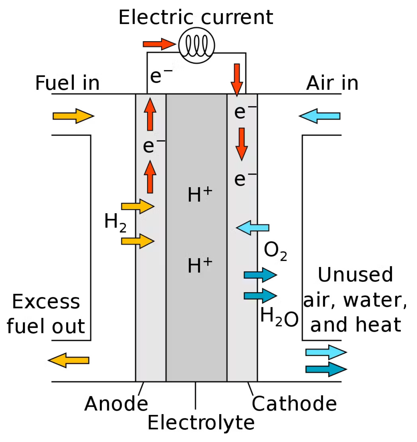
Figure 1. Piecewise linearization of the electricity consumption of electrolyzers.
Sustainability 17 06117 g001
Figure 2. Piecewise linearization of the electricity consumption of fuel cells.
Sustainability 17 06117 g002
Figure 3. Comparison of discharge time and power rating for various electricity storage technologies.
Sustainability 17 06117 g003
Figure 4. Decision framework of a single-stage capacity expansion problem.
Sustainability 17 06117 g004
Figure 5. Decision framework of a multi-stage capacity expansion problem.
Sustainability 17 06117 g005
Figure 6. Electricity markets’ ancillary services. FM: futures market; DAM: day-ahead market; AMs: adjustment markets; BM: balancing market; FCR: frequency containment reserve; aFRR: automatic frequency restoration reserve; mFRR: manual frequency restoration reserve.
Sustainability 17 06117 g006
Figure 7. Diagram of a hydrogen fuel cell used in FCEVs (Wikipedia Commons).
Sustainability 17 06117 g007
Figure 8. Simplified schema of ammonia production using electrolysis.
Sustainability 17 06117 g008
Figure 9. Simplified schema of ammonia production using biomass gasification.
Sustainability 17 06117 g009
Table 1. Comparison of electrolyzers and fuel cells [27,28,29,30,31,32,33,34,35,36,37,38].
TypeElectrolyteTemp. (°C)Efficiency (%)Advantages and Disadvantages
Electrolyzers
AEKOH or NaOH60–8060–70+ Mature technology, low cost.
− Low current density, sensitive to impurities.
PEMPolymer membrane50–8070–85+ High efficiency, fast response.
− Expensive catalysts, requires pure water.
SOECeramic (YSZ)650–100085–90+ High efficiency, can use steam.
− High temperature, material degradation.
AEMEAnion exchange membrane50–8065–75+ Cheaper than PEM, no precious metals.
− Lower durability, still in development.
Fuel Cells
PEMFCProton exchange membrane50–10040–60+ Fast startup, compact design.
− Expensive catalysts, management issues.
DMFCDirect methanol60–13030–40+ Liquid fuel convenience, high energy density.
− Methanol crossover, low electrical efficiency.
SOFCCeramic (YSZ)600–100050–65+ High efficiency, fuel flexibility.
− High temp., slow startup.
PAFCPhosphoric acid150–20040–50+ Tolerant to impurities.
− Large size, slow startup.
AFCKOH60–9045–55+ High efficiency, low-cost catalysts.
CO 2 sensitivity, requires pure hydrogen.
MCFCMolten carbonate salts600–70045–55+ High efficiency, fuel flexibility.
− Corrosion issues, slow startup.
Table 2. Technical comparison of hydrogen storage methods.
MethodKey ParametersAdvantagesDisadvantagesTypical Applications
Compressed
Hydrogen
  • Pressure: 350–700 bar
  • Temp.: Ambient
  • Operational simplicity
  • High storage capacity
  • Compression energy
  • Leakage losses
FCEVs
Liquid
Hydrogen
  • Temp.: −253 °C
  • High vol. density
  • Efficient transport
  • Higher density
  • Costly liquefaction
  • Boil-off losses
Space, large-scale
Metal
Hydrides
  • Low P/T
  • Solid-state
  • Safe (non-volatile)
  • High vol. density
  • Material costs
  • Slow kinetics
Stationary storage
Chemical
Storage
( NH 3 /LOHCs)
  • Compounds: NH 3 /LOHCs
  • Release by reaction
  • Conventional logistics
  • High energy density
  • Complex processes
  • Regeneration energy
Long-distance
Power
to
Methane
  • Sabatier: H 2 + CO 2 CH 4
  • Uses gas infrastructure
  • Existing networks
  • CO 2 utilization
  • Reduced efficiency
  • Catalyst costs
Gas grids/seasonal
Table 3. Scope of the planning models and optimization frameworks.
Ref.ModelGenerationGridStorage H 2 Prod. H 2 Trans. H 2 StorageFormulationUncertaintyStages
[143]REMixR,C,N,GyPH,B--TA,GSLPDSS
[144]REMixG--E-GSLPDSS
[145]ad hocR--E,TW,Bio-TAMILPDSS
[146]PyPSA-Eur-Sec-30R,GyB,H2E-TALPDSS
[147]ad hocR,N,H2yPH,B,H2E-TALPDSS
[148]ad hocR,G,H2yH2E,SMRPTA,GSMILPDMS
[149]PRIMESR,C,N,G,H2-PH,B,CA,H2E,SMR--NLPDMS
[151]ad hocR-BE,BioTRTAMILPDMS
[150]ad hocR,C,G-PH,B,ThE-nsLPDMS
[152]ad hocR,G,N,H2yB,H2E,SMRPTALPDSS
[153]ad hocR,C,G,H2-BE,SMR--LPDSS
[101]ad hoc---E-TAMILPDSS
[154]EnertileR,N,H2yPH,H2E-nsLPDSS
[155]REMixR,C,N,GyPH,B,CA,Th,H2E-GSLPDSS
[104]ad hocR,H2-BE-TAMILPSSS
[156]REMixR,GyPH,B,ThEP,RFTA,GSLPDMS
[158]ad hoc---E,SMRP,TRTA,TR,PMILP(LP)DSS
[157]ad hocR,GyBEP,RF,TRTALPDSS
[159]LIMES-EUR,C,N,G,H2yPH,B,H2E-nsLPDMS
[160]REMixR,N,H2yPH,BEP,MTA,GSLPDSS
[161]METISGyPH,BE,SMRP,RFGSLPDSS
[164]ad hocR--EP-MISOCPSSS
[167]ad hocR,G,Ny-E,SMRP,RF-LPDSS
[168]ad hocR,Gy-EP,RFGSLPDSS
[163]REMixR,GyPH,BEPGSLPDSS
[162]PyPSA-Eur-Sec-30R,C,N,GyBE,SMRPTA,GSLPDMS
[165]ad hoc-y-E,SMRP,TRnsMILPDSS
[166]ad hoc---E--MINLP(MISOCP)SSS
[106]ad hocR,G,H2-PH,BE-TAMILPSSS
[169]ad hocRy-EP,TRTA,TRMINLP(MILP)DMS
[171]BalmorelR,C,N,GynsE,SMRP,RFnsLPDMS
[170]COMPETESR,C,N,GyPH,B,CAE,SMRP,RFnsLPDSS
[172]ad hocR-BE,SMRP,TRTA,P,TRMILPDSS
[173]ad hocR,H2-H2EPTAMINLP(MILP)DMS
Table 4. Summary of H2 vehicle integration.
ThemeReferences
FCEVs and grid integration[164,213,214,227,228,229]
Energy system planning, including FCEVs[211,212,220,221,222,223]
Techno-economic analysis of H 2 refueling stations[209,210,224,225]
Renewable-based production with FCEVs[204,226]
H2 as an energy carrier and sector coupling[202,203,204,217]
Forecasting and adoption of FCEVs[206,207,208]
Electrolyzer Modeling and Flexibility with FCEVs[215,216,217,218,219]
Table 5. Summary of green ammonia production using electrolysis.
ParameterApproximate ValueUnitReferences
Electrolytic conversion efficiency65–75%[27,28,29,30,31,32,33,34,35,36]
Electricity consumed10–12MWh/ton NH3[258,259]
HB + ASU capital cost4192EUR/ton NH3/h[260]
Annual total production cost415–840EUR/ton NH3[260,261]
CO2 footprint0.34–0.95ton CO2/ton NH3[262]
Plant lifetime20–30years[260]
HB: Haber–Bosch unit; ASU: air separation unit.
Disclaimer/Publisher’s Note: The statements, opinions and data contained in all publications are solely those of the individual author(s) and contributor(s) and not of MDPI and/or the editor(s). MDPI and/or the editor(s) disclaim responsibility for any injury to people or property resulting from any ideas, methods, instructions or products referred to in the content.

