Abstract
The complex climate in permafrost regions poses severe challenges to infrastructure, and freeze-thaw cycles accelerate the deformation and damage of road embankments. Conventional thermosyphon technology, though effective in lowering permafrost temperatures, has a limited range of effect, making it hard to meet the demand for large-scale temperature regulation. This paper proposes a V-shaped transverse thermosyphon design with bidirectional heat conduction. It connects at the embankment centerline and transversely penetrates the entire cross-section to expand the temperature regulation range. Using a hydro-thermal coupling model, the temperature regulation effects of vertical, inclined, and V-shaped thermosyphons were calculated. Results show that the V-shaped design outperforms the other two in temperature control across different embankment areas. Transverse temperature analysis indicates uniform cooling around the embankment center, while depth temperature analysis reveals more stable temperature control with lower and less fluctuating temperatures at greater depths. Long-term temperature analysis demonstrates superior annual temperature regulation, providing consistent cooling. This research offers a scientific basis for embankment temperature regulation design in permafrost regions and is crucial for ensuring long-term embankment stability and safety.
1. Introduction
In permafrost regions, the complex natural environment poses a serious challenge to infrastructure construction. As a special geological body, the unique thermodynamic and mechanical properties of permafrost have a profound impact on the stability, durability, and service life of embankment engineering [1,2,3]. Peng Hui et al. [4] found that freeze-thaw cycles and unfrozen water migration in permafrost further intensify embankment deformation and damage. Qin Xiaotong et al. [5] established a non-saturated frozen soil hydro-thermal migration model, proposing a hydro-thermal coupling theory for slope stability under rainfall infiltration. They discovered that rainfall intensity and initial water content greatly influence slope stability. Hong Wenjiang et al. [6] observed that slope soil freeze-thaw mainly occurs in the shallow layer, with snowfall directly linked to slope failure, and the failure mode of silty clay slopes transitioning from shallow slides to overall failure with rising groundwater levels during the spring thaw. Tong Rui et al. [7] measured the frost heave process of railway embankments in the Wuwei section of the Lanzhou-Xinjiang Railway, putting forward the “time-varying cover effect” to explain water migration and frost heave.
In summary, temperature regulation to ensure the stability and durability of road embankments in permafrost regions is a promising research direction. Actively cooling embankments with a thermosyphon is a commonly used measure for permafrost embankment treatment [8,9,10,11]. This technology can bring out the heat in the embankment and reduce the temperature of the embankment, thus inhibiting the degradation of frozen soil and increasing the stability of the embankment [12,13,14]. Thermosyphon technology has an obvious effect on controlling the differential settlement of embankments in permafrost areas, which helps improve driving comfort and ensure the safe and fast driving of vehicles. It is of great significance to promote technological progress in road construction in China and promote the development of the regional economy [15]. At the same time, the thermosyphon technology does not require external energy and is environmentally friendly. It can reduce the ecological risks caused by permafrost degradation and has the advantages of low cost and maintenance-free, reducing the life cycle cost. Therefore, the thermosyphon has a broad market prospect in protecting the sustainable development of permafrost embankment. Currently, there is a lack of innovative design solutions and systematic research on thermosyphons that can effectively address the temperature regulation requirements of large-scale and uniform temperature distribution in permafrost embankments.
In this paper, through an indoor model test and numerical simulation analysis, combined with the actual climatic conditions, the cooling process is simulated, and the design parameters and structural forms of the thermosyphon are optimized. The thermosyphon parameters and setting methods suitable for the permafrost slope of the Qinghai-Tibet Plateau are proposed [16,17]. The thermal behavior of a permafrost embankment after thermosyphon treatment is studied, and the thermal behavior characteristics and dynamic response of a thermosyphon permafrost subgrade under traffic load are analyzed. This research aims not only to fill the knowledge gap in large-scale and uniform temperature regulation of permafrost embankments but also to contribute to the sustainable development of infrastructure in permafrost regions by providing a more reliable and efficient temperature regulation solution for embankment engineering.
2. V-Shaped Bidirectional Heat Conduction Thermosyphon
In the existing research, the heat exchange process of the thermosyphon is shown in Figure 1. The temperature control effect of the thermosyphon is limited by its range of action and usually only works effectively within a range of 3 to 5 meters [18,19]. It is difficult to meet the uniform control requirements of frozen soil temperature in a wide range. Especially in the vicinity of the central line of the subgrade, the effect of the thermosyphon is small, resulting in the failure of effective temperature control of the frozen soil in this area, which will lead to the thawing of the frozen soil at the central line of the road faster than other locations, resulting in road cracking between the central line area and other locations [13,20]. This lack of local temperature control may affect the stability of the frozen soil layer, which, in turn, affects the long-term safety of the road and the comfort of driving.
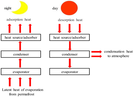
Figure 1.
Heat exchange process diagram.
In order to overcome this problem, an innovative design scheme is proposed: under the flexible retaining structure, a V-shaped transversely penetrating thermosyphon is used, as shown in Figure 2. In recent years, the L-shaped thermosyphon has been widely studied by scholars. It slightly reduces the temperature drop range in exchange for a larger temperature control range than the direct-inserted thermosyphon and the obliquely-inserted thermosyphon. Compared with it, the design of the thermosyphon runs through the lower part of the entire road width, so that the heat can be evenly distributed throughout the roadbed range. At the same time, heat transfer between the thermosyphons on both sides of the subgrade is realized, avoiding uneven temperature control in traditional designs. This laying method not only ensures effective temperature control of the frozen soil layer in the whole range of the road but also improves the heat conduction efficiency of the thermosyphon system and enhances the stability and safety of the frozen soil in the roadbed. In this way, it can achieve a more balanced and efficient temperature control effect, effectively improve the impact of frozen soil on the roadbed, and provide a more reliable guarantee for the long-term use of the road. This innovative design aims to fill the knowledge gap in large-scale and uniform temperature regulation of permafrost embankments by conventional thermosyphons, thereby promoting the sustainable development of infrastructure in permafrost regions.
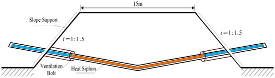
Figure 2.
Design scheme of thermosyphon.
This design adopts the natural convection mechanism. The basic principle is, due to the uneven distribution of air temperature, the air density in the area with higher temperature is smaller, and the air density in the area with lower temperature is larger, which leads to the spontaneous flow of air from the high-density area to the low-density area, thus triggering natural convection. In the application of ventilated anchors, when the temperature gradient inside and outside the slope is external heat and internal cooling, the air inside the anchor remains stable and no convection occurs; when the temperature gradient inside and outside the slope is external cold and internal heat, the density of hot air at the bottom is small, and the density of cold air at the top is large. Under the action of gravity, the hot air on the slope and the cold air outside the slope have natural convection, which continuously removes the heat inside the slope.
The heat transfer mechanism of this design uses the condensation section and evaporation section of the thermosyphon, like conventional technology. It is used to absorb the excess heat of the soil. The working medium is liquid ammonia. The heat transfer concept diagram is shown in Figure 3.
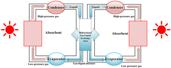
Figure 3.
Concept diagram of bidirectional thermal conduction through type thermosyphon heat transfer.
The arrangement of the thermosyphon can be carried out in parallel with the construction. After a certain height of soil is arranged or a certain depth of soil is excavated, the structure is embedded in the soil, and then the soil is filled and compacted above it. Due to the influence of compaction, soil weight, and pavement load, a certain deflection deformation will be caused to the pipe body in the soil. Therefore, in the design, we use a pipe body material that can withstand the pressure of the soil and has a certain toughness. At the same time, we reduce the deflection at the time of embedding to avoid structural damage caused by excessive deformation under various loads in the future.
In winter, the external temperature is lower than the temperature of the frozen soil. This design can release the heat of the frozen soil layer and prevent the melting of the frozen soil. In summer, because the ambient temperature is higher than the temperature of the frozen soil layer around the heat absorption section of the thermosyphon, the liquid ammonia in the thermosyphon will not absorb the heat in the frozen soil, so the thermosyphon stops working.
3. Heat-Moisture-Deformation Coupling Model
3.1. Geometric Model and Material Parameters
A two-dimensional geometric model of the subgrade is established. The grid is constructed through the mutual mapping of hexahedral and tetrahedral units, and the grid is set to ultra-fine mode to improve calculation accuracy. The maximum size of the unit is 1.75 m, the minimum size is 0.075 m, the maximum unit growth rate is 1.35, the curvature factor is 0.3, and the narrow area resolution is 0.85. Among them, the maximum unit growth rate of 1.35 refers to the expansion speed of the grid from the dense area to the sparse area. The smaller the value, the more smoothly the grid size changes; the curvature factor of 0.3 is used to control the mesh density of the curved part in the model. The smaller the value, the finer the mesh of the curved area, such as the bend and the slope. The narrow area resolution of 0.85 ensures that the details of the narrow parts in the model can be accurately captured, and the higher the value, the better the fine structure can be seen. In the model, the width of the road surface is 18 m, the total thickness of the road surface and the base layer is 0.6 m, the height of the subgrade filling is 2.7 m, and the slope gradient is 1:1.5; there are 7 m thick clay layer, 15 m thick strong weathering and weak weathering rock layer under the subgrade, and the natural ground width on both sides of the subgrade is 18.65 m. The specific model and meshing are shown in Figure 4 and Figure 5.
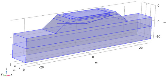
Figure 4.
Specific model.
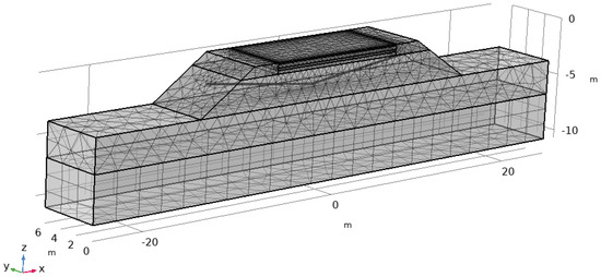
Figure 5.
Mesh divide.
The thermal physical parameters of the subgrade pavement structure and foundation are shown in Table 1. In order to simplify the model, the water content in the pavement structure is considered to be 0, so the phase change is not considered. According to the relevant literature, the upper and lower limits of the subgrade phase transition interval are set to 0 °C and −0.4 °C, respectively, the upper and lower limits of the clay phase transition interval are set to 0 °C and −1 °C, respectively, and the upper and lower limits of the bedrock phase transition interval are set to 0 °C and −0.6 °C, respectively. The latent heat of soil is L × ω/(1 + ω), where L is the latent heat of ice-water phase change, 334.56 kJ/kg.

Table 1.
Thermodynamic and physical parameters of each layer.
3.2. Governing Equation
The atmosphere-thermosyphon-frozen soil constitutes a working system. When the specific parameters of each part of the system are determined, the heat exchange strength between the frozen soil and the thermosyphon during the thermosyphon work is determined by the temperature difference. In this process, the coupling heat transfer process between the thermosyphon and the soil is shown in Figure 6.
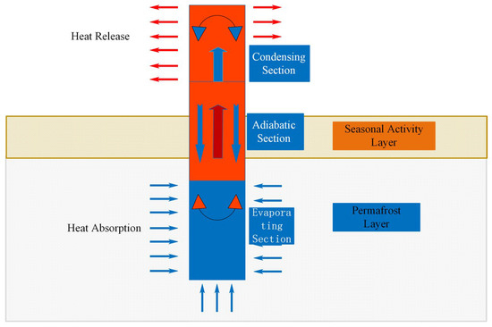
Figure 6.
Schematic diagram of frozen soil thermosyphon coupling.
The heat transfer of the thermosyphon is:
Here, Q stands for heat transfer of thermosyphon per unit time, F for heat exchange area, for the difference between the soil temperature and the atmospheric environment temperature in the evaporation section of the thermosyphon, and α for the convective heat transfer coefficient of air and the condensation section of the thermosyphon.
α is given by the following empirical formula:
Here, Nua is Nusselt: dimensionless criterion number, namely fluid Nusselt number; λa is thermal conductivity of air; d0 for outside diameter of steel pipe; Rea is Reynold: dimensionless criterion number, namely fluid Reynolds number; Pra is Prandtl: dimensionless criterion number, that is, fluid Prandtl number; S is net spacing of fins; H is fin height; δ is fin thickness; ρa is air density; νa is average wind speed; μa is aerodynamic viscosity; Cpa is air constant pressure specific heat.
The total heat transfer area F of the fins is calculated by the following formula:
Fin surface area Af1:
Tube surface area between fins Af1:
Total heat transfer area F:
Substituting the physical parameters at different temperatures into the above formulas, the results related to them are shown in Table 2:
Table 2.
Table of Changes in Air-Related Parameters with Temperature.
The above calculation represents the convective heat transfer coefficient of the condensation section, according to the literature [21]. The effective heat transfer coefficient of the evaporation section is given by the following formula:
The formula includes the following parameters: T0 represents the temperature on one side of the evaporation section of the thermosyphon, Te is the temperature on the frozen soil side, λ is the thermal conductivity coefficient of the frozen soil, L is the length of the evaporation section, and d0 is the outer diameter of the hot rod in the evaporation section.
However, the temperature T0 on one side of the evaporation section of the thermosyphon cannot be determined. Considering that the heat absorption power of the evaporation section must be less than the heat dissipation power of the condensation section, and the heat transfer efficiency coefficient a is introduced, that is, the power ratio of the condensation section to the evaporation section.
When the parameters and size of the thermosyphon are determined, a is a function of temperature difference and wind speed. According to the engineering experience, a is between 0.1 and 0.3. For the in-line thermosyphon, a = 0.2 is taken in this paper. When the temperature difference between the soil in the evaporation section and the external environment exceeds 0.8 °C, the working condition of the thermosyphon is reached, and the thermosyphon begins to work to bring heat from the soil to the atmospheric environment. When the temperature difference is less than 0.8 °C, the thermosyphon stops working.
The heat flux q of the evaporation section of the thermosyphon is given by Equation (11):
The formula incorporates the following parameters: αe represents the effective convective heat transfer coefficient with units of, d0 is the outer diameter of the thermosyphon in millimeters, and l is the length of the evaporation section.
According to Fourier’s law, the heat transfer in the evaporation section of the thermosyphon satisfies Equation (12):
In the formula, λ represents the thermal conductivity of the soil.
The evaporation section of the thermosyphon is the coupling boundary between the thermosyphon and the frozen soil, and the rationality of Equation (12) needs to be further explained. Through the mathematical transformation of the coupling boundary, the heat transferred from the soil to the atmosphere through the thermosyphon Q is as follows:
The formula incorporates several critical parameters: Te represents the temperature at the contact interface between the thermosyphon and the soil, Ta is atmospheric temperature, Ra is the convective heat transfer thermal resistance outside the condensation section of the atmosphere and thermosyphon, Rw,c is the thermal resistance of the tube wall in the condensation section of the thermosyphon, Rc is the condensation heat transfer resistance of steam, Re is evaporative thermal resistance, and Rw,e is the thermal resistance of heat conduction through the evaporation section tube wall.
In the formula, Ae represents the heat transfer area between the soil and the evaporation section of the thermosyphon.
Compared to the thermal resistances of air convection heat transfer and soil heat conduction, the thermal resistances of phase change heat transfer and thin-walled heat conduction in the thermosyphon are much smaller. In order to simplify the model, the internal thermal resistance and side wall thermal resistance of the thermosyphon can be ignored. Equation (14) is simplified as follows:
The equivalent convective heat transfer coefficient is introduced as ; the above formula is simplified to . According to the simplification, it can be seen that the heat exchange between the soil and the evaporation section of the hot rod satisfies the third boundary condition, such as Equation (16):
The formula incorporates two key parameters: Ta represents atmospheric temperature in degrees Celsius, and λ is the thermal conductivity of the soil.
3.3. Model Verification
In order to explore the thermal stability of subgrades in cold regions, this study uses a numerical simulation method to analyze the temperature field evolution law of natural foundations and artificial subgrades. Firstly, the thermodynamic model of natural foundation is established. The initial temperature is set to 0 °C, and the steady-state temperature field under the disturbance of the upper boundary temperature over a hundred years is simulated as the initial condition for subgrade construction.
Aiming at the test section of Jingmo Highway (subgrade width: 12 m, filling height: 2.7 m), the mitigation effect of thermosyphon technology on the annual average temperature rise is studied, as shown in Figure 7. Considering the construction thermal disturbance (initial temperature of 20 °C) during modeling, the evolution characteristics of the subgrade temperature field during 30 years of operation are predicted. The formation parameters of the model are determined according to the actual project: the total thickness of the pavement structure is 0.84 m (including modified asphalt surface layer and cement stabilized base layer), and the lower part is 7 m clay layer and 15 m weathered rock layer.
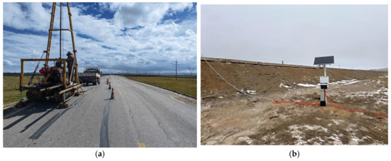
Figure 7.
Field experiment. (a) Drilling machine construction, (b) GNSS receiver.
The reliability of the model is verified by comparing the ground temperature monitoring data. As shown in Figure 8, the simulated ground temperature curve on January 1 of the following year is consistent with the trend of the measured data of the shoulder drilling. Table 3 shows that in the depth range of 0 to −7 m, the maximum temperature difference between the calculated value and the measured value is 0.53 °C (−7 m), and the relative error is ≤9.2%. It is worth noting that the error at −3 m approaches zero, while the error between shallow (−2 m) and deep (−5 m, −7 m) increases significantly.
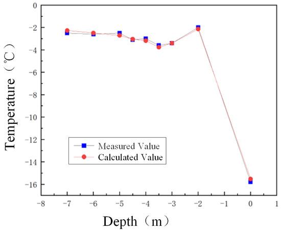
Figure 8.
Comparison chart of ground temperature distribution curves.
Table 3.
Error analysis.
The error is mainly due to the contradiction between the homogenization assumption of the model and the heterogeneity of the field soil, especially since complex factors, such as ice-water phase transitions and local material inhomogeneities, are not considered. Nevertheless, the overall agreement between the simulation results and the measured data (average error of 4.8%) shows that this model can provide an effective reference for the evaluation of the thermal stability of subgrades in cold regions.
4. Analysis of Temperature Regulation Efficiency
In order to study the specific working state of the three kinds of thermosyphons and the annual change of the subgrade temperature field over one year, the temperature field of the subgrade during one year after the thermosyphon works stably for 10 years is analyzed.
4.1. Cross-Section Temperature Field Analysis
In the cross-section where the center point of the pavement is four meters down, points at 0, 3, 7, 9, and 11 m from the subgrade center are selected. The temperature changes in the tenth year under the three types of thermosyphons are recorded, as shown in Figure 9.
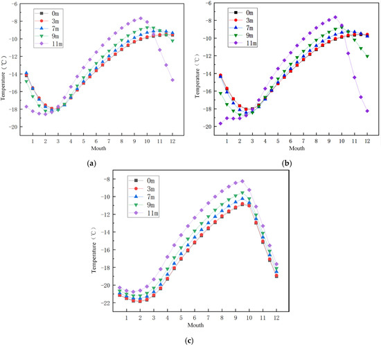
Figure 9.
Temperature distribution diagram of three types of thermosyphons along the cross-section. (a) Direct-inserted thermosyphon, (b) Obliquely-inserted thermosyphon, and (c) Bidirectional heat conduction thermosyphon.
From the figure, there is little difference in the performance of the three thermosyphons from May to November. From November to the next May, the temperature regulation effect of the direct-inserted and oblique-inserted thermosyphons on points near the subgrade center is poor and uneven. The temperature change curve of the bidirectional heat conduction thermosyphon shows that the temperature changes at different distances are consistent. The temperature is low in winter, with small temperature differences at each distance. The temperature rise in summer is minimal, and the overall frozen soil temperature remains low. The cooling effect of the bidirectional heat conduction thermosyphon in the subgrade center and its surrounding area is relatively uniform, effectively maintaining lower temperatures. This indicates that the bidirectional heat conduction thermosyphon performs well in overall temperature regulation and provides a stable cooling effect.
4.2. Depth Temperature Field Analysis
A point is taken every 0.75 m down the center of the road until 3 m, a total of five points. The temperature changes from December of the tenth year to April of the eleventh year under the action of three kinds of thermosyphons were recorded, as shown in Figure 10.
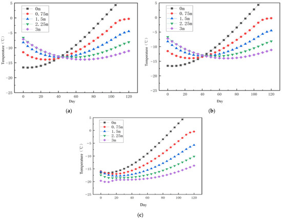
Figure 10.
Temperature distribution map of three types of thermosyphons along depth. (a) Direct-inserted thermosyphon, (b) Obliquely-inserted thermosyphon, and (c) Bidirectional heat conduction thermosyphon.
It can be seen from the figure that the temperature change trends of the direct-inserted thermosyphon and the oblique-inserted thermosyphon along the depth are similar, and the temperature approaches, with no obvious advantages or disadvantages. These two kinds of thermosyphons have a better control effect on shallow temperatures, but with an increase in depth, the control effect on subgrade temperatures obviously decreases. With an increase in depth, the temperature control ability of the bidirectional heat conduction thermosyphon becomes more stable. The deep temperature is lower, and the change range is smaller and more uniform than the other two thermosyphons. This shows that the bidirectional heat conduction thermosyphon has a better overall temperature adjustment effect and can provide a stable cooling effect.
Take a point every 0.5 m down the center of the road until 4 m, a total of nine points. The temperature changes along the depth on December 1 of the tenth year, under the action of three kinds of thermosyphons, were recorded, as shown in Figure 11.
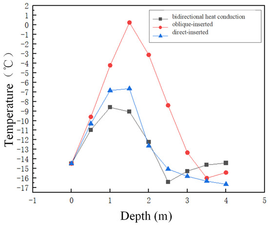
Figure 11.
Temperature distribution map of three types of thermosyphon along the shoulder downward.
As shown in the diagram, the temperature adjustment of the inclined oblique-inserted thermosyphon is not ideal at a shallow depth (1 to 2 m), but as the depth increases, the temperature decreases significantly. The temperature control effect of the bidirectional heat conduction thermosyphon is close to that of the direct-inserted thermosyphon, but its temperature change is relatively stable. Under its influence, the temperature change of the shoulder depth is relatively small, showing better temperature regulation stability.
4.3. Long-Term Temperature Field Analysis
Take the point 3 m below the center point of the road surface, and record the temperature change of the same point within 1 year under the action of three kinds of thermosyphons, as shown in Figure 12.
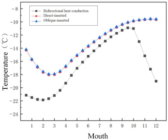
Figure 12.
Long term temperature distribution diagram of three types of thermosyphon.
It can be seen from the figure that the overall temperature distribution of the direct-inserted thermosyphon and the oblique-inserted thermosyphon is highly similar throughout the year. The temperature under the direct-inserted thermosyphon control is slightly lower than the temperature under the oblique-inserted thermosyphon control. From May to November, when the thermosyphon stops working, the effects of the three thermosyphons on temperature regulation are close. In October and November, due to the work of the bidirectional heat conduction thermosyphons, the subgrade temperature was rapidly reduced to −20 °C, while the temperature of the other two thermosyphons was only regulated to −10 °C. The subgrade temperature under the control of the bidirectional heat conduction thermosyphon is lower than the subgrade temperature under the other two thermosyphons within the whole year, which indicates that the temperature control effect of the bidirectional heat conduction thermosyphon is better than the other two in the whole year, which can provide a stable cooling effect.
4.4. Analysis of Slope Foot Temperature Field
Take a point every 0.75 m down the slope toe until 3 m, a total of five points. The temperature changes under the action of three kinds of thermosyphons are recorded, as shown in Figure 13.
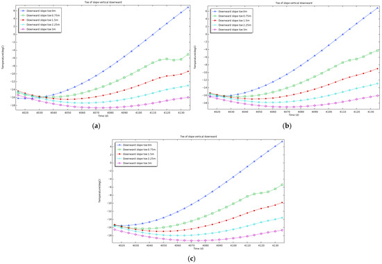
Figure 13.
Temperature distribution map of three types of thermosyphons along the foot of the slope downward. (a) Direct-inserted thermosyphon, (b) Obliquely-inserted thermosyphon, and (c) Bidirectional heat conduction thermosyphon.
It can be seen from the figure that the three thermosyphons have similar temperature control effects on the toe of the slope, and there are no obvious advantages or disadvantages. This shows that the bidirectional heat conduction thermosyphon ensures that the temperature control effect in other areas is better than that of the other two thermosyphons, and also ensures that the temperature control at the foot of the slope is not inferior to that of the other two thermosyphons.
4.5. Analysis of Regional Temperature Field
Compared with the Qinghai-Tibet Plateau, Northeast China (such as Harbin) is extremely cold in winter. Controlled by the Siberian High the cold air moves south frequently, and the annual minimum temperature can reach − 30 °C. Due to the regulation of the monsoon, the temperature difference between day and night is relatively small, with an annual maximum temperature of about 10 °C. North China (non-plateau) is affected by the northwest monsoon in winter, and the annual minimum temperature can reach −10 °C. In the summer, it is affected by the southeast monsoon, with high temperatures and rain, and the annual maximum temperature can reach 30 °C. The frozen soil types in Northeast China and North China are seasonal frozen soil. The main function of the thermosyphon is to accelerate heat dissipation in winter to reduce frost heave, and to reduce heat absorption in summer to alleviate thaw settlement, so as to improve road stability. In contrast, the permafrost on the Qinghai-Tibet Plateau requires continuous heat dissipation throughout the year to maintain the low temperature state of the permafrost and prevent permafrost degradation caused by thermal disturbances or climate warming. By comparing the temperature regulation effects of the three provinces’ thermosyphons at the center of the subgrade, down 4 m (Figure 14), it can be clearly seen that the adaptability of the thermosyphons under different climatic and frozen soil conditions and their effective regulation of frozen soil temperature.
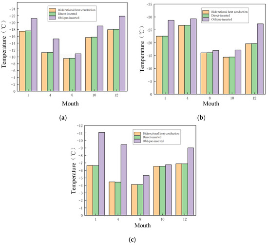
Figure 14.
Temperature distribution map of three types of thermosyphons along the foot of the slope downward. (a) Tibet plateau area, (b) Northeast China, and (c) North China.
By analyzing these three figures, it can be found that the temperature regulation effect of the bidirectional heat conduction thermosyphon is the best in all three regions. Although the direct-inserted and oblique-inserted thermosyphons exhibit relatively stable temperature regulation effects, their range of influence is limited, and their overall effect is weaker. The bidirectional heat conduction thermosyphon’s range of influence can cover the subgrade center, while the oblique-inserted and direct-inserted thermosyphons cannot reach the subgrade center, with almost negligible temperature control effects on the subgrade center. In the high-temperature period of summer, the temperature regulation effects of the three thermosyphons are less ideal. However, the temperature of the bidirectional heat conduction thermosyphon at the subgrade center is significantly lower than that of the oblique-inserted and direct-inserted thermosyphons, indicating better temperature regulation performance. The climatic conditions and frozen soil characteristics of different regions significantly affect the temperature regulation effects of thermosyphons. Due to the low-temperature environment and frozen soil issues in the Qinghai-Tibet Plateau and Northeast China, the demand for thermosyphon temperature regulation is more significant. In contrast, the relatively high temperatures and less severe frozen soil problems in North China result in a smaller demand for temperature regulation. Considering regional climate conditions, subgrade frozen soil characteristics, and specific project requirements, the bidirectional heat conduction thermosyphon should be prioritized. In areas with high temperatures and less severe frozen soil problems, thermosyphons with better stability, such as direct-inserted and oblique-inserted thermosyphons, can be considered. In general, the bidirectional heat conduction thermosyphon provides the best temperature regulation performance, better ensuring the stability and safety of the project.
5. Conclusions and Prospect
- (1)
- Innovatively put forward the V-shaped transverse through the tiled bidirectional heat conduction type thermal rod (V-shaped bidirectional heat conduction type thermosyphon), to ensure the uniform distribution of the temperature field of the whole section of the subgrade, to make up for the traditional thermosyphon temperature control range, which is limited. This work contributes to the sustainable development of infrastructure in permafrost regions by offering a more reliable and efficient temperature regulation solution.
- (2)
- Based on the COMSOL (6.2 version) numerical platform, the hydro-thermal coupling analysis model of permafrost embankment is established, and the effective prediction and rapid simulation of the permafrost embankment temperature field are realized. Such a model helps optimize the design of temperature regulation systems for embankments, reducing energy consumption and environmental impact, and thus supports the sustainable development of infrastructure in permafrost regions.
- (3)
- The numerical analysis shows that the bidirectional heat conduction thermosyphon has significant advantages in controlling the subgrade cross-sectional temperature field, depth temperature field, and long-term temperature field. Its temperature control stability, uniformity, and temperature fluctuations are superior to those of direct-inserted and oblique-inserted thermosyphons.
- (4)
- At the foot of the embankment slope, the temperature regulation effect of the bidirectional heat conduction thermosyphon is consistent with the performance of the direct-inserted thermosyphon and oblique-inserted thermosyphon.
- (5)
- In the seasonal frozen soil area, the temperature regulation effect of the bidirectional heat conduction thermosyphon is significantly better than that of the direct-inserted thermosyphon and oblique-inserted thermosyphon. This indicates that the bidirectional heat conduction thermosyphon has better adaptability to different climate conditions, which is crucial for the sustainable development of infrastructure in cold regions.
In terms of the application and popularization value of this research, the V-shaped bidirectional heat conduction thermosyphon presents significant potential. For infrastructure construction in permafrost regions, this innovative design can be widely applied to ensure the temperature stability of road embankments, thereby enhancing the safety and longevity of transportation infrastructure. It provides a technical approach for addressing the challenges posed by permafrost degradation due to climate change. In the context of global climate change and increasing demands for infrastructure in cold regions, the research findings are not only of great theoretical significance but also hold substantial practical value for engineering applications. This study provides a new possibility for future research and development of thermosyphon technology, with the potential to develop standardized design and implementation guidelines for thermosyphon systems in permafrost regions.
The research on the V-shaped bidirectional heat conduction thermosyphon presented in this paper provides a new approach for temperature regulation of embankments in permafrost regions. However, there are still several areas that require further exploration and improvement:
- (1)
- Although the V-shaped design shows advantages in temperature regulation, further optimization of its geometric parameters (such as the angle of the thermosyphon) could potentially enhance its performance.
- (2)
- Investigating new materials with higher thermal conductivity and better durability for thermosyphons could improve their efficiency and lifespan.
Author Contributions
Conceptualization, F.D. and B.T.; Methodology, L.Q.; Software, S.H. and L.Q.; Validation, L.Q.; Formal analysis, F.D. and B.T.; Investigation, F.D. and S.H.; Resources, F.D.; Data curation, S.H.; Writing—original draft, F.D. and B.T.; Writing—review & editing, F.D., B.T., S.H. and L.Q.; Supervision, B.T. All authors have read and agreed to the published version of the manuscript.
Funding
This research received no external funding.
Institutional Review Board Statement
Not applicable.
Informed Consent Statement
Not applicable.
Data Availability Statement
The original contributions presented in this study are included in the article. Further inquiries can be directed to the corresponding author.
Conflicts of Interest
The authors declare no conflict of interest.
References
- Wei, Y.; Xue, X. Exploration of the stability of slope embankment in permafrost regions. J. Railw. Eng. 2011, 28, 35–39. [Google Scholar]
- Gao, F.; Zeng, X.; Zhong, W.; Huang, S.; Zhang, J. Research Progress and Prospect of Road Engineering Disease Treatment Technology in Permafrost Regions. Chin. Foreign Highw. 2024, 44, 1–16. [Google Scholar]
- Wang, S.; Chen, J.; Jin, L.; Dong, Y. Research Progress and Prospect of Scale Effect Theory of Frozen Soil Subgrade. Ind. Build. 2023, 53, 45–53. [Google Scholar]
- Peng, H.; Chen, J.; Wang, Z.; Ma, W.; Mu, Y. Heat affected zone of road engineering in permafrost region of Qinghai-Tibet Plateau. China J. Highw. 2015, 28, 92–99. [Google Scholar]
- Qin, X.; Cui, K.; Qing, Y. Rainfall infiltration law and infiltration mechanism of seasonal frozen soil slope under hydrothermal coupling. China Highw. J. 2022, 35, 12. [Google Scholar]
- Hong, W.; Xu, X.; Yu, H. Groundwater seepage model test of slope in seasonal frozen area. Sci. Technol. Eng. 2017, 17, 9. [Google Scholar]
- Tong, R.; Song, E.; Zhao, Z. Measurement of frost heave process of a railway subgrade and analysis of “time-varying coverage effect”. J. Railw. Sci. Eng. 2020, 17, 8. [Google Scholar]
- Smith, L.B.; Graham, J.P.; Nixon, J.F.; Washuta, A.S. Thermal analysis of force air and thermosyphon cooling system for the inuvik airport expansion. Can. Geotech. J. 1991, 28, 399–409. [Google Scholar] [CrossRef]
- Sun, W.; Wu, Y.; Guo, C.; Zhang, L. Effects of hot rod on the stability of permafrost subgrade. China J. Highw. 2009, 22, 15–20. [Google Scholar]
- Wang, S.; Chen, J.; Jin, L.; Dong, Y.; Chen, D. Theoretical study on highway design in permafrost regions based on energy balance. Glaciol. Permafr. 2014, 36, 782–789. [Google Scholar]
- Li, Y.; Wu, Z.; Wang, Y. Experimental study on the application effect of hot rod on permafrost subgrade of Qinghai-Tibet Railway. China Railw. Sci. 2008, 29, 6–11. [Google Scholar]
- Liu, G.; Wang, S.; Jin, L.; Dong, Y.; Yuan, K. Application effect of hot rod subgrade in permafrost regions. Transp. Eng. J. 2016, 16, 59–67. [Google Scholar]
- Sheng, Y.; Wen, Z.; Ma, W.; Wu, J. Three-dimensional nonlinear analysis of temperature field of hot rod subgrade in permafrost region of Qinghai-Tibet Railway. Railw. J. 2006, 28, 125–130. [Google Scholar]
- Zhang, J. Study on Design Technology of Highway Subgrade in Permafrost Regions; Graduate School of Chinese Academy of Sciences: Beijing, China, 2008. [Google Scholar]
- Feng, G. Past, present and future of permafrost subgrade engineering research in China. Glaciol. Permafr. 2009, 31, 139–147. [Google Scholar]
- Wang, L.; Li, G.; Chen, Y. Design and calculation method of thermosyphon subgrade in permafrost regions based on the principle of heat budget balance. Geotech. Mech. 2020, 41, 529–536. [Google Scholar]
- Jin, L.; Wang, S.; Mu, K.; Peng, H. Cooling efficiency of hot rod subgrade of Qinghai-Tibet Highway. Glaciol. Permafr. 2016, 38, 529–536. [Google Scholar]
- Xu, J.F.; Goering, D.J. Experimental validation of passive permafrost cooling systems. Cold Reg. Sci. Technol. 2008, 53, 283–297. [Google Scholar] [CrossRef]
- Sun, Z.Z.; Ma, W.; Li, D.Q. In situ test on cooling effectiveness of air convection embankment with crushed rock slope protection in permafrost regions. J. Cold Reg. Eng. 2005, 19, 38–51. [Google Scholar]
- Sun, Z.K.; Wang, L.J.; Bai, M.Z.; Wei, Q.C. Finite element analysis of temperature field in permafrost embankment of Qinghai-Tibet Railway. J. Rock Mech. Eng. 2004, 23, 3454–3459. [Google Scholar]
- Wang, F. Numerical Simulation and Vibration Characteristics Analysis of Environmental Vibration of High-Speed Railway Based on ABAQUS; Beijing Jiaotong University: Beijing, China, 2014. [Google Scholar]
Disclaimer/Publisher’s Note: The statements, opinions and data contained in all publications are solely those of the individual author(s) and contributor(s) and not of MDPI and/or the editor(s). MDPI and/or the editor(s) disclaim responsibility for any injury to people or property resulting from any ideas, methods, instructions or products referred to in the content. |
© 2025 by the authors. Licensee MDPI, Basel, Switzerland. This article is an open access article distributed under the terms and conditions of the Creative Commons Attribution (CC BY) license (https://creativecommons.org/licenses/by/4.0/).