
Underground Hydrogen Storage in Salt Cavern: A Review of Advantages, Challenges, and Prospects

 ,
,  ,
,
Abstract
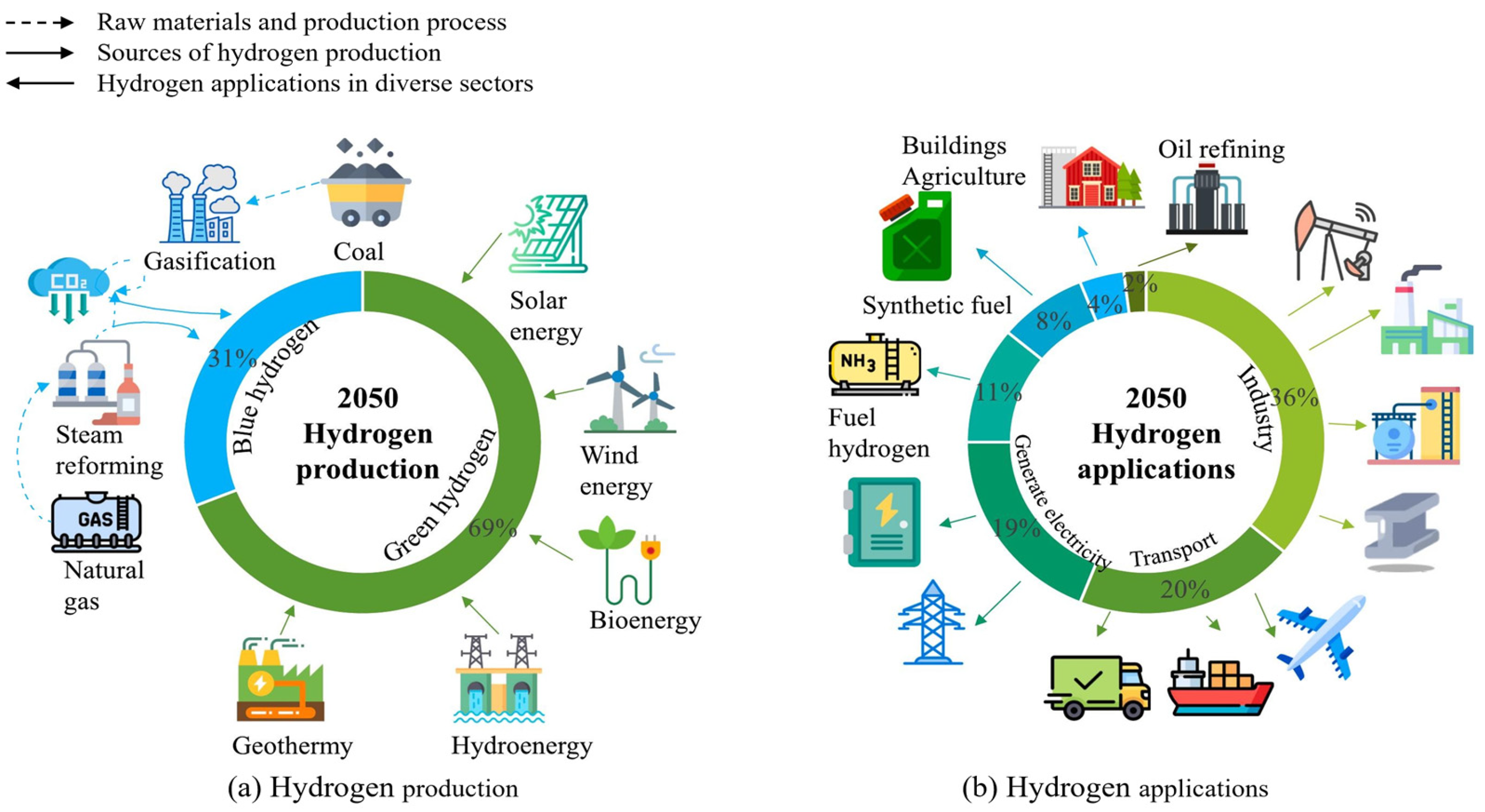
1. Introduction
2. Fundamentals of Salt Caverns for Hydrogen Storage
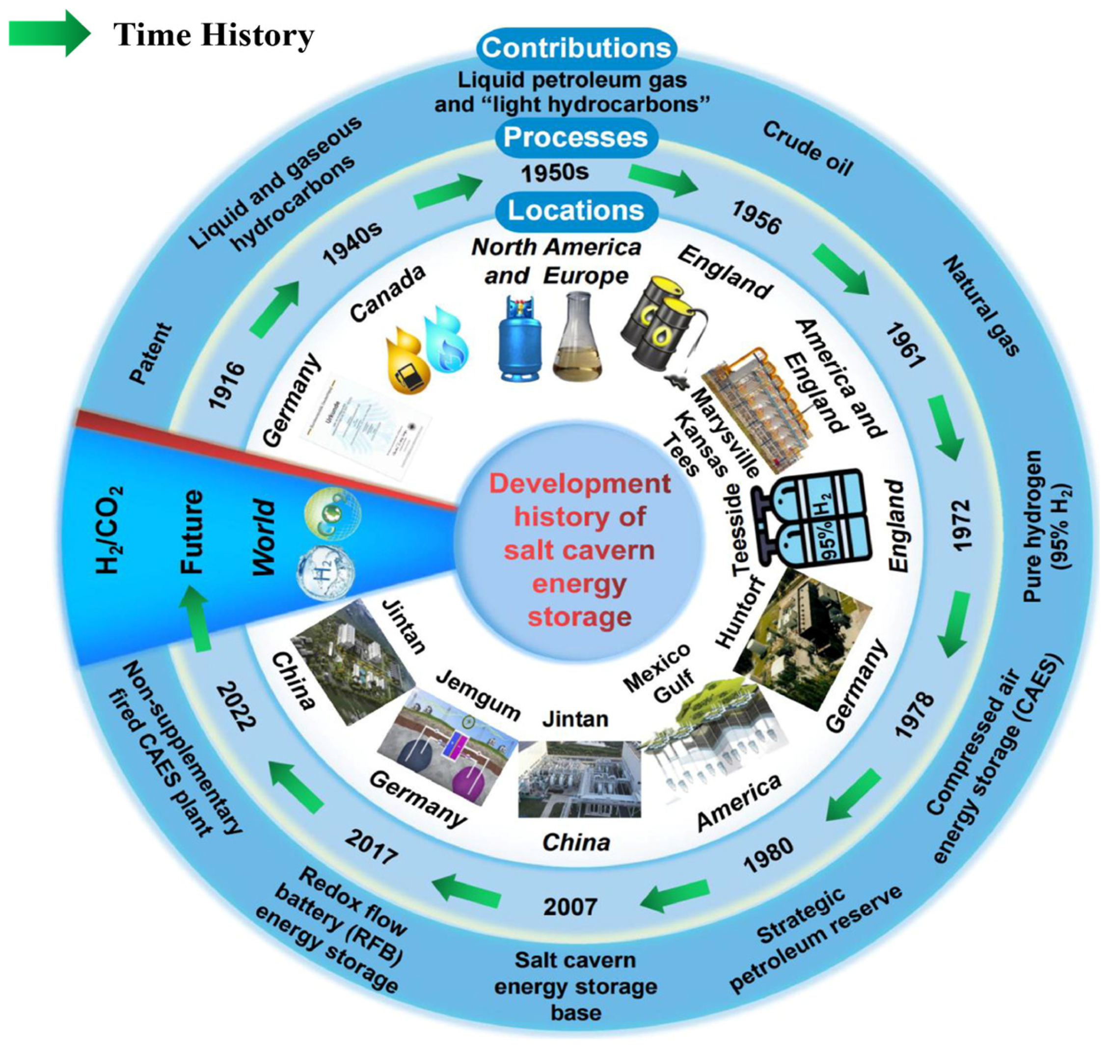
2.1. Global Existing Projects
2.2. Geological Formation
2.3. Key Properties
2.4. Design and Construction
3. Advantages of Salt Caverns for Hydrogen Storage
3.1. Technical Benefits
3.2. Economic Viability
3.3. Environmental and Safety Benefits
4. Challenges and Limitations
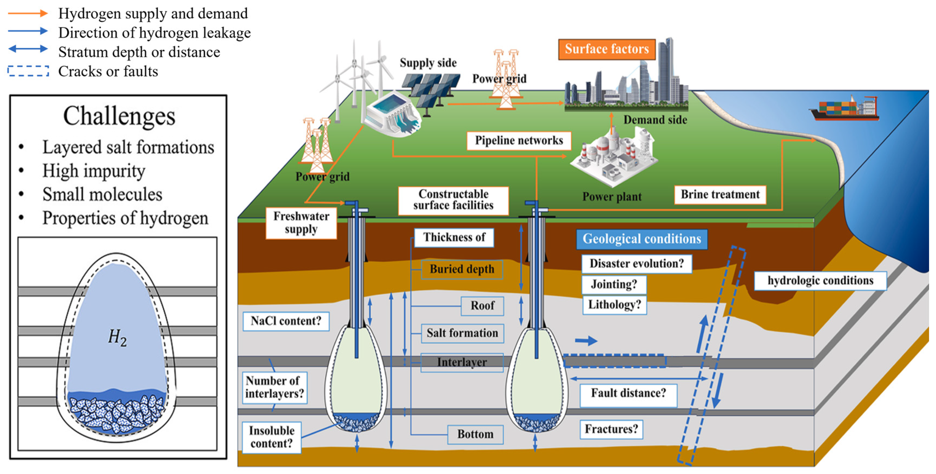
4.1. Technical Challenges
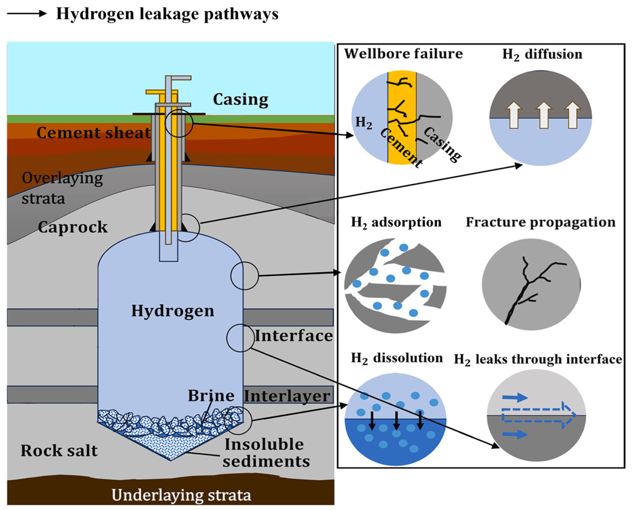
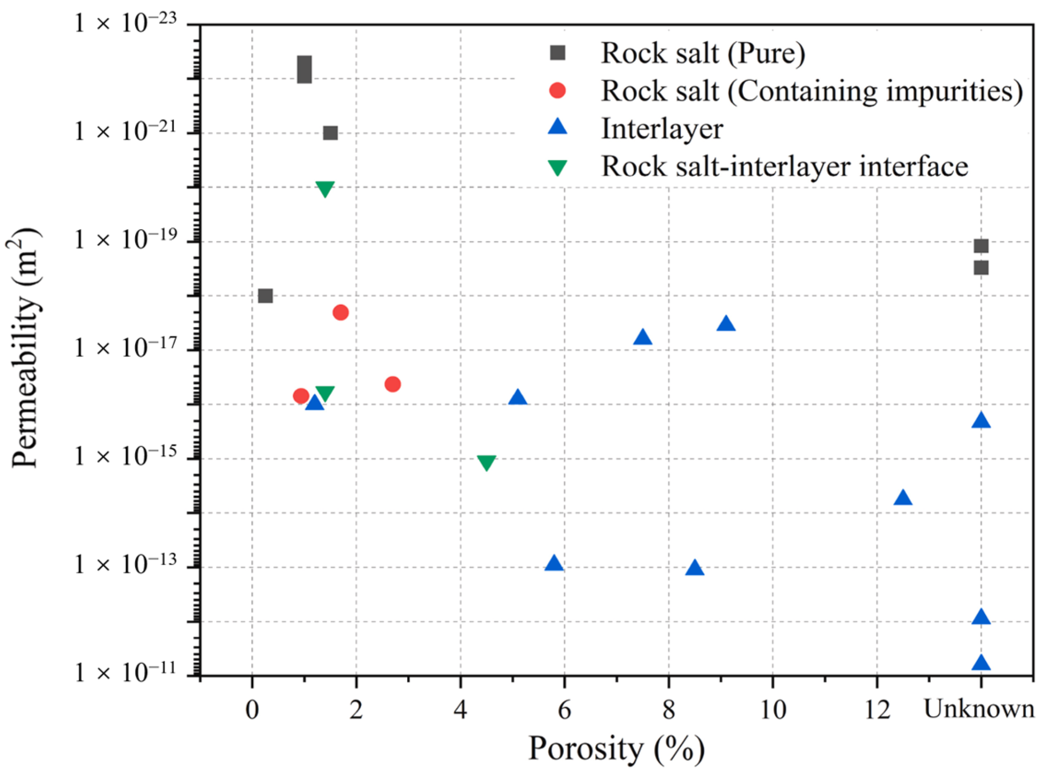
4.1.1. Hydrogen Leakage and Interlayer Risks
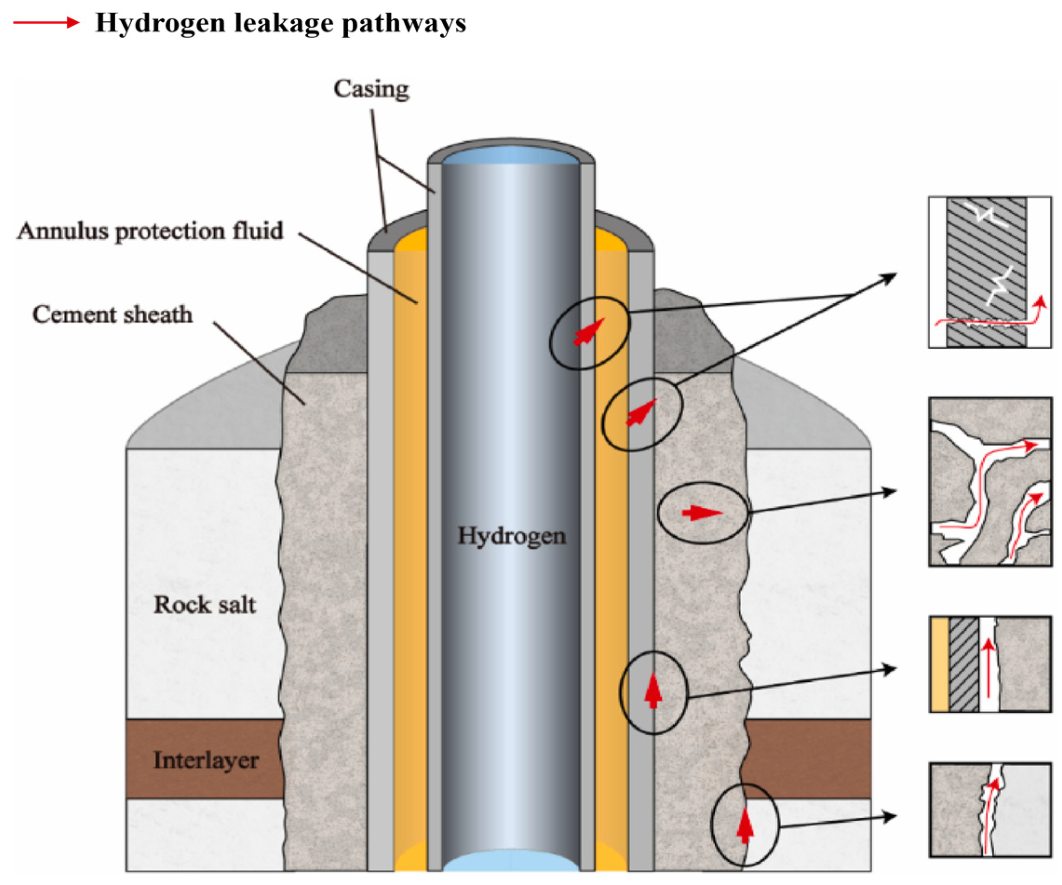
4.1.2. Wellbore Integrity Failure
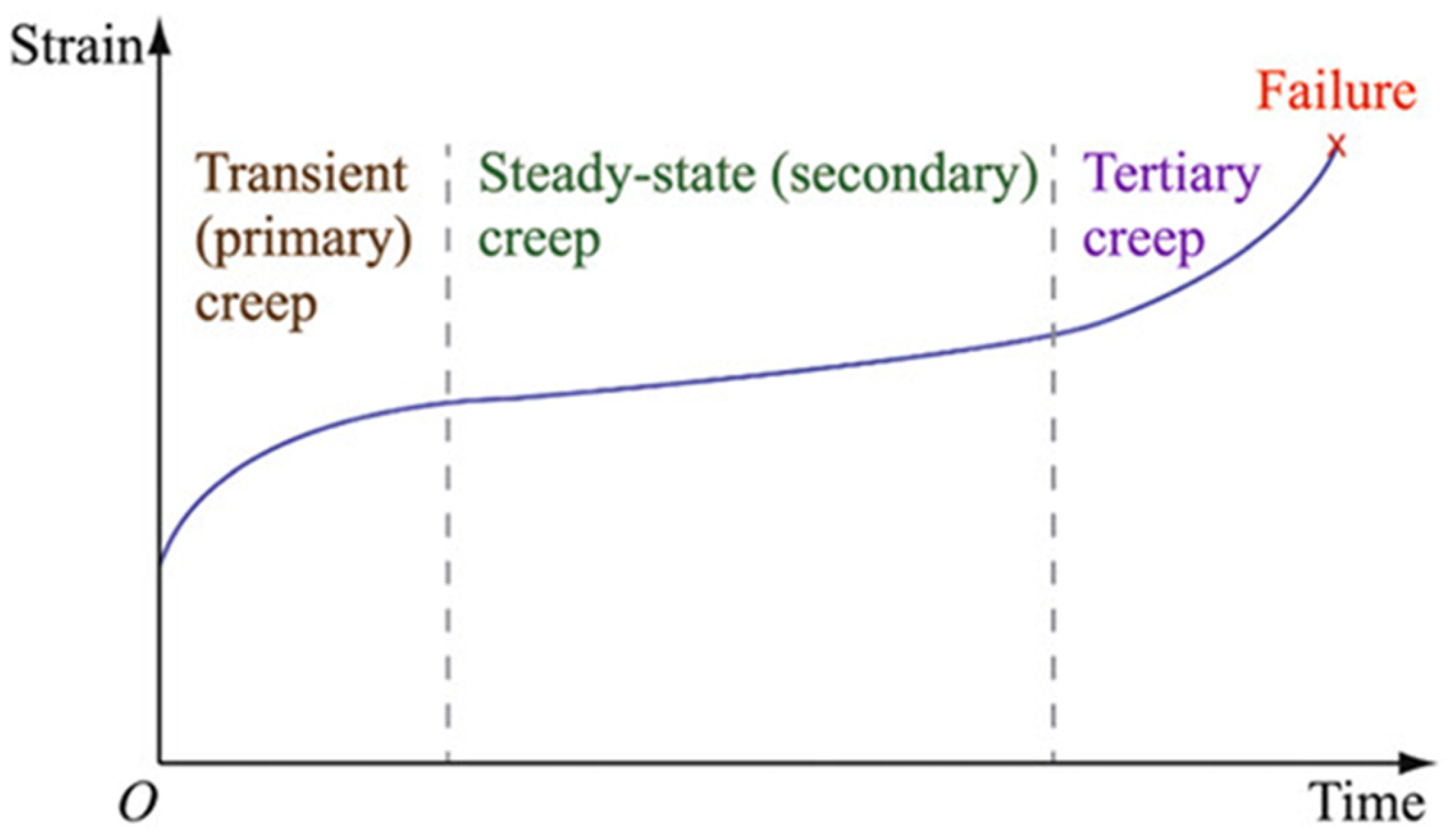
4.1.3. Long-Term Geomechanical
4.1.4. Chemical Evolution and Earthquake Risk
4.2. Economic and Regulatory Barriers
4.3. Social and Environmental Concerns
5. Prospects and Future Directions
5.1. Technological Innovations
5.2. Policy and Market Drivers
5.3. Integration with the Hydrogen Economy
6. Case Studies and Global Applications
6.1. Global Practical Experience and China’s Geological Hydrogen Storage Challenges
6.2. Site Selection Technical Standards and Evaluation System
6.3. Key Technological Innovations and Engineering
6.4. Regional Potential and Development Prospects
7. Conclusions
Author Contributions
Funding
Data Availability Statement
Acknowledgments
Conflicts of Interest
References
- Net Zero by 2050—Analysis. Available online: https://www.iea.org/reports/net-zero-by-2050 (accessed on 7 May 2025).
- Liao, Q.; Wang, B.; Chen, X.; Tan, P. Reservoir Stimulation for Unconventional Oil and Gas Resources: Recent Advances and Future Perspectives. Adv. Geo-Energy Res. 2024, 13, 7–9. [Google Scholar] [CrossRef]
- Caglayan, D.G.; Weber, N.; Heinrichs, H.U.; Linßen, J.; Robinius, M.; Kukla, P.A.; Stolten, D. Technical Potential of Salt Caverns for Hydrogen Storage in Europe. Int. J. Hydrogen Energy 2020, 45, 6793–6805. [Google Scholar] [CrossRef]
- Leng, G.; Yan, W.; Chen, Z.; Li, Z.; Liu, B.; Deng, P.; Zhang, C.; Liu, W.; Qi, H. Technical Challenges and Opportunities of Hydrogen Storage: A Comprehensive Review on Different Types of Underground Storage. J. Energy Storage 2025, 114, 115900. [Google Scholar] [CrossRef]
- Pan, B.; Yin, X.; Ju, Y.; Iglauer, S. Underground Hydrogen Storage: Influencing Parameters and Future Outlook. Adv. Colloid Interface Sci. 2021, 294, 102473. [Google Scholar] [CrossRef]
- Wan, J.; Sun, Y.; He, Y.; Ji, W.; Li, J.; Jiang, L.; Jurado, M.J. Development and Technology Status of Energy Storage in Depleted Gas Reservoirs. Int. J. Coal Sci. Technol. 2024, 11, 29. [Google Scholar] [CrossRef]
- Olabi, A.G.; Wilberforce, T.; Ramadan, M.; Abdelkareem, M.A.; Alami, A.H. Compressed Air Energy Storage Systems: Components and Operating Parameters—A Review. J. Energy Storage 2021, 34, 102000. [Google Scholar] [CrossRef]
- Wu, D.; Wang, J.G.; Yang, S.-Q. A Coupled Thermo-Hydro-Mechanical Model for Evaluating Air Leakage from an Unlined Compressed Air Energy Storage Cavern. Renew. Energy 2020, 146, 907–920. [Google Scholar] [CrossRef]
- Dai, J.; Liu, J.; Ran, L.; Lin, H.; He, X.; Bian, Y. Acoustic Emission Characteristics and Energy Evolution of Salt Rock for Deep-Salt-Cavern Engineering under Triaxial Loading and Unloading. J. Cent. South Univ. 2023, 30, 962–974. [Google Scholar] [CrossRef]
- Liang, X.; Meng, T.; Feng, G.; Zhao, G.; Wang, Z.; Liu, P. Evolution of Permeability and Pore Structure of Salt Rock and Its Self-Healing Mechanism under Coupled Thermo-Hydro-Mechanical Environment. J. Energy Storage 2023, 66, 107476. [Google Scholar] [CrossRef]
- Ozarslan, A. Large-Scale Hydrogen Energy Storage in Salt Caverns. Int. J. Hydrogen Energy 2012, 37, 14265–14277. [Google Scholar] [CrossRef]
- Cao, Q.; Jia, M.; Li, B.; Shen, C.; Xue, X. Decisions of a Byproduct Hydrogen Supply Chain for a Business Model of Large-Scale Hydrogen Storage. J. Tsinghua Univ. (Sci. Technol.) 2023, 63, 2019–2032. [Google Scholar] [CrossRef]
- Jiang, D.Y.; Jiang, C.Q.; Chen, J.; Kang, Y.F.; Liu, W.; Du, C. Experimental study of the self-healing property of damaged salt rock by Brazilian splitting. Chin. J. Eng. 2020, 42, 570–577. [Google Scholar] [CrossRef]
- Raza, A.; Arif, M.; Glatz, G.; Mahmoud, M.; Al Kobaisi, M.; Alafnan, S.; Iglauer, S. A Holistic Overview of Underground Hydrogen Storage: Influencing Factors, Current Understanding, and Outlook. Fuel 2022, 330, 125636. [Google Scholar] [CrossRef]
- Liu, W.; Li, Q.; Yang, C.; Shi, X.; Wan, J.; Jurado, M.J.; Li, Y.; Jiang, D.; Chen, J.; Qiao, W.; et al. The Role of Underground Salt Caverns for Large-Scale Energy Storage: A Review and Prospects. Energy Storage Mater. 2023, 63, 103045. [Google Scholar] [CrossRef]
- Iaremchuk, I.; Tariq, M.; Hryniv, S.; Vovnyuk, S.; Meng, F. Clay Minerals from Rock Salt of Salt Range Formation (Late Neoproterozoic–Early Cambrian, Pakistan). Carbonates Evaporites 2017, 32, 63–74. [Google Scholar] [CrossRef]
- Schwab, L.; Popp, D.; Nowack, G.; Bombach, P.; Vogt, C.; Richnow, H.H. Structural Analysis of Microbiomes from Salt Caverns Used for Underground Gas Storage. Int. J. Hydrogen Energy 2022, 47, 20684–20694. [Google Scholar] [CrossRef]
- Zeng, L.; Keshavarz, A.; Xie, Q.; Iglauer, S. Hydrogen Storage in Majiagou Carbonate Reservoir in China: Geochemical Modelling on Carbonate Dissolution and Hydrogen Loss. Int. J. Hydrogen Energy 2022, 47, 24861–24870. [Google Scholar] [CrossRef]
- Wallace, R.L.; Cai, Z.; Zhang, H.; Zhang, K.; Guo, C. Utility-Scale Subsurface Hydrogen Storage: UK Perspectives and Technology. Int. J. Hydrogen Energy 2021, 46, 25137–25159. [Google Scholar] [CrossRef]
- Bo, Z.; Zeng, L.; Chen, Y.; Xie, Q. Geochemical Reactions-Induced Hydrogen Loss during Underground Hydrogen Storage in Sandstone Reservoirs. Int. J. Hydrogen Energy 2021, 46, 19998–20009. [Google Scholar] [CrossRef]
- Didier, M.; Leone, L.; Greneche, J.-M.; Giffaut, E.; Charlet, L. Adsorption of Hydrogen Gas and Redox Processes in Clays. Environ. Sci. Technol. 2012, 46, 3574–3579. [Google Scholar] [CrossRef]
- He, A.; Ma, Q.; Liu, T.; Li, J.; Zhang, H.; Dai, K.; Lu, Y. Study on Sealing Integrity Mechanism of Salt Cavern Hydrogen Storage under Alternating Load. In Proceedings of the ARMA US Rock Mechanics/Geomechanics Symposium, Atlanta, GA, USA, 25–28 June 2023; p. ARMA-2023-699. [Google Scholar]
- Chang, K.W.; Ross, T.S.A. Cyclic Loading-Unloading Impacts on Salt Cavern Stability: Implication for Underground Hydrogen Storage. In Proceedings of the ARMA US Rock Mechanics/Geomechanics Symposium, Golden, CO, USA, 23–26 June 2024. [Google Scholar]
- Park, B.Y. Geomechanical Evaluation of the Stability of the Caprock Roof and Salt Boundary of an Abandoned Cavern in Salt Dome. In Proceedings of the ARMA US Rock Mechanics/Geomechanics Symposium, New York, NY, USA, 23–26 June 2019; p. ARMA-2019-370. [Google Scholar]
- Li, X.; Huang, W.; Wu, X.; Zhang, J.; Wang, Y.; Akiyama, E.; Hou, D. Effect of Hydrogen Charging Time on Hydrogen Blister and Hydrogen-Induced Cracking of Pure Iron. Corros. Sci. 2021, 181, 109200. [Google Scholar] [CrossRef]
- Sun, Y.; Frank Cheng, Y. Hydrogen-Induced Degradation of High-Strength Steel Pipeline Welds: A Critical Review. Eng. Fail. Anal. 2022, 133, 105985. [Google Scholar] [CrossRef]
- Campari, A.; Ustolin, F.; Alvaro, A.; Paltrinieri, N. A Review on Hydrogen Embrittlement and Risk-Based Inspection of Hydrogen Technologies. Int. J. Hydrogen Energy 2023, 48, 35316–35346. [Google Scholar] [CrossRef]
- Nassan, T.H.; Kirch, M.; Amro, M. Underground Hydrogen Storage in Salt Caverns: Laboratory Experiments to Determine Integrity of Rock Salt and Wellbore through Effective Permeability Measurements. Int. J. Hydrogen Energy 2025, 99, 619–631. [Google Scholar] [CrossRef]
- Minougou, J.D.; Gholami, R.; Andersen, P. Underground Hydrogen Storage in Caverns: Challenges of Impure Salt Structures. Earth Sci. Rev. 2023, 247, 104599. [Google Scholar] [CrossRef]
- Naderi, H.; Hekmatnejad, A.; Aftab, A.; Sarmadivaleh, M.; Pena, A. Integrating 1D and 3D Geomechanical Modeling to Ensure Safe Hydrogen Storage in Bedded Salt Caverns: A Comprehensive Case Study in Canning Salt, Western Australia. Int. J. Hydrogen Energy 2024, 81, 1073–1090. [Google Scholar] [CrossRef]
- Ji, Z.; Liu, J.; Cai, Y.; Yang, J.; Yi, H.; Jiang, L.; Wei, J.; Hassanpouryouzband, A. Technical Characteristics and Developmental Prospect of Hydrogen Storage in Salt Cavern: A Perspective of Layered Salt Rocks. Renew. Sustain. Energy Rev. 2025, 213, 115451. [Google Scholar] [CrossRef]
- How Kiel Became Germany’s First Zero Waste City. Available online: https://www.weforum.org/stories/2024/04/kiel-zero-waste-city/ (accessed on 7 June 2025).
- Net Zero Teesside|The UK’s First Decarbonised Industrial Cluster. Available online: https://www.netzeroteesside.co.uk/ (accessed on 7 June 2025).
- Clemens Salt Dome Gas Storage Facility. Available online: https://clui.org/ludb/site/clemens-salt-dome-gas-storage-facility (accessed on 7 June 2025).
- Advanced Clean Energy Storage. Available online: https://www.energy.gov/lpo/advanced-clean-energy-storage (accessed on 7 June 2025).
- NeuVentus Announces Moss Bluff Project. Available online: https://www.lotusinfrastructure.com/news/ (accessed on 7 June 2025).
- Simon, J.; Ferriz, A.M.; Correas, L.C. HyUnder—Hydrogen Underground Storage at Large Scale: Case Study Spain. Energy Procedia 2015, 73, 136–144. [Google Scholar] [CrossRef]
- HyStock. Available online: https://www.hystock.nl/en (accessed on 7 June 2025).
- Höpken, L.; Bekebrok, H.; Pluta, A.; Langnickel, H.; Savchenko, I.; Ohm, M.; Steinmann, O.; Zobel, M.; Dyck, A.; Agert, C. Modelling Green Hydrogen Storage in Salt Caverns: Implications of Future Storage Demands on Cavern Operation. J. Energy Storage 2025, 119, 116150. [Google Scholar] [CrossRef]
- HyCavMobil—NOW GmbH. Available online: https://www.now-gmbh.de/en/projectfinder/hycavmobil-2/ (accessed on 7 June 2025).
- Aldbrough Hydrogen Storage. Available online: https://www.aldbroughhydrogen.com (accessed on 7 June 2025).
- Ye County Will Build a Salt Cavern Compressed Air Energy Storage Power Station. Available online: https://www.seetao.com/details/93490.html (accessed on 7 June 2025).
- U.S. Department of Energy. Technology Readiness Assessment Guide. Lawrence Berkeley National Laboratory. 2011. Available online: https://www2.lbl.gov/DIR/assets/docs/TRL%20guide.pdf (accessed on 25 June 2024).
- Song, Y.; Song, R.; Liu, J. Hydrogen Tightness Evaluation in Bedded Salt Rock Cavern: A Case Study of Jintan, China. Int. J. Hydrogen Energy 2023, 48, 30489–30506. [Google Scholar] [CrossRef]
- Wang, T.T.; Ma, H.L.; Shi, X.L.; Yang, C.H.; Zhang, N.; Li, J.L.; Ding, S.L.; Daemen, J.J.K. Salt Cavern Gas Storage in an Ultra-Deep Formation in Hubei, China. Int. J. Rock Mech. Min. Sci. 2018, 102, 57–70. [Google Scholar] [CrossRef]
- Zhao, K.; Liu, Y.; Li, Y.; Ma, H.; Hou, W.; Yu, C.; Liu, H.; Feng, C.; Yang, C. Feasibility Analysis of Salt Cavern Gas Storage in Extremely Deep Formation: A Case Study in China. J. Energy Storage 2022, 47, 103649. [Google Scholar] [CrossRef]
- Keprta, G.L. Clemens North, Clemens Southwest, Clemens Northeast, and Clemens Dome Fields; Houston Geological Society: Houston, TX, USA, 1987. [Google Scholar]
- Wang, S.; Wang, H.; Wu, Z.; Li, M.; Xing, W. Physical Simulation Technologies and Testing System for Cavern Shape Control from Single-Well Solution Mining in Rock Salt. Rev. Sci. Instrum. 2022, 93, 125101. [Google Scholar] [CrossRef] [PubMed]
- Peng, T.; Wan, J.; Liu, W.; Li, J.; Xia, Y.; Yuan, G.; Jurado, M.J.; Fu, P.; He, Y.; Liu, H. Choice of Hydrogen Energy Storage in Salt Caverns and Horizontal Cavern Construction Technology. J. Energy Storage 2023, 60, 106489. [Google Scholar] [CrossRef]
- Liu, X.; Chen, H.; Huang, Y.; Safaei-Farouji, M.; Ostadhassan, M. An Indication of Salt Caprock Failed Integrity in Inclusion Records: Dongpu Depression, Bohai Bay Basin, China. Mar. Pet. Geol. 2023, 148, 106016. [Google Scholar] [CrossRef]
- Talukdar, M.; Blum, P.; Heinemann, N.; Miocic, J. Techno-Economic Analysis of Underground Hydrogen Storage in Europe. Iscience 2024, 27, 108771. [Google Scholar] [CrossRef]
- Li, Z.; Kang, Y.; Fan, J.; Fourmeau, M.; Chen, J.; Jiang, D.; Nelias, D. Macroscopic Experimental Study and Microscopic Phenomenon Analysis of Damage Self-Healing in Salt Rock. Eng. Geol. 2024, 338, 107634. [Google Scholar] [CrossRef]
- Moslehy, A.; Alshibli, K.A. Influence of Temperature and Deviatoric Stress on Creep Behavior of Rock Salt. IOP Conf. Ser. Earth Environ. Sci 2023, 1124, 12018. [Google Scholar] [CrossRef]
- Zhang, Q.; Song, Z.; Wang, J.; Zhang, Y.; Wang, T. Creep Properties and Constitutive Model of Salt Rock. Adv. Civ. Eng. 2021, 2021, 8867673. [Google Scholar] [CrossRef]
- Hou, B.; Shangguan, S.; Niu, Y.; Su, Y.; Yu, C.; Liu, X.; Li, Z.; Li, J.; Liu, X.; Zhao, K. Unique Properties of Rock Salt and Application of Salt Caverns on Underground Energy Storage: A Mini Review. Energy Sources Part A Recovery Util. Environ. Eff. 2024, 46, 621–635. [Google Scholar] [CrossRef]
- Wang, J.; Wu, R.; Wei, M.; Bai, B.; Xie, J.; Li, Y. A Comprehensive Review of Site Selection, Experiment and Numerical Simulation for Underground Hydrogen Storage. Gas Sci. Eng. 2023, 118, 205105. [Google Scholar] [CrossRef]
- Ling, D.; Zhu, S.; Wang, J.; Yang, P.; Wu, J.; Liu, G.; Chen, Y.; Xu, W.; Zhuang, D.; Li, J. Experimental Study on Shape Expansion and Construction Efficiency of Horizontal Hydrogen Storage Salt Caverns in Bedded Salt. Int. J. Hydrogen Energy 2025, 114, 508–518. [Google Scholar] [CrossRef]
- Wang, T.; Yan, X.; Yang, H.; Yang, X.; Jiang, T.; Zhao, S. A New Shape Design Method of Salt Cavern Used as Underground Gas Storage. Appl. Energy 2013, 104, 50–61. [Google Scholar] [CrossRef]
- Liebscher, A.; Wackerl, J.; Streibel, M. Geologic Storage of Hydrogen—Fundamentals, Processing, and Projects. In Hydrogen Science and Engineering: Materials, Processes, Systems and Technology; John Wiley & Sons, Ltd.: Hoboken, NJ, USA, 2016; pp. 629–658. ISBN 978-3-527-67426-8. [Google Scholar]
- Sambo, C.; Dudun, A.; Samuel, S.A.; Esenenjor, P.; Muhammed, N.S.; Haq, B. A Review on Worldwide Underground Hydrogen Storage Operating and Potential Fields. Int. J. Hydrogen Energy 2022, 47, 22840–22880. [Google Scholar] [CrossRef]
- Jiang, H.; Yu, H.; Mao, C.; Tang, Z.; Li, L.; Ofi, A.; Burns, C.; Wang, Y.; Wen, T.; Gui, F.; et al. The Practice and Effect of Underground Gas Storage Expanding the Range of Operation Pressure beyond the Original Reservoir Pressure to Increase Gas Storage Capacity. In Proceedings of the SPE Europec featured at EAGE Conference and Exhibition, Turin, Italy, 26–28 June 2024; p. D021S015R005. [Google Scholar]
- Wang, B.; Li, D.; Xu, B.; Zhang, Y.; Zhang, F.; Wang, Q.; Yang, B. Probabilistic-Based Geomechanical Assessment of Maximum Operating Pressure for an Underground Gas Storage Reservoir, NW China. Geomech. Energy Environ. 2022, 31, 100279. [Google Scholar] [CrossRef]
- Xie, P.; Wen, H.J.; Wang, G.J.; Hu, J. Theoretical Analytical Solution of Deformation and Stress Distribution of Underground Gas Storage Cavern in Bedded Salt Rock. Arch. Civ. Eng. 2018, 64, 37–53. [Google Scholar] [CrossRef]
- Wang, J.; Zhang, Q.; Song, Z.; Feng, S.; Zhang, Y. Nonlinear Creep Model of Salt Rock Used for Displacement Prediction of Salt Cavern Gas Storage. J. Energy Storage 2022, 48, 103951. [Google Scholar] [CrossRef]
- Tang, Y.; Li, Y. Comparative Analysis of the Levelized Cost of Hydrogen Production from Fossil Energy and Renewable Energy in China. Energy Sustain. Dev. 2024, 83, 101588. [Google Scholar] [CrossRef]
- Lord, A.S.; Kobos, P.H.; Borns, D.J. Geologic Storage of Hydrogen: Scaling up to Meet City Transportation Demands. Int. J. Hydrogen Energy 2014, 39, 15570–15582. [Google Scholar] [CrossRef]
- Liu, J.; Pei, J.; Wei, J.; Yang, J.; Xu, H. Development Status and Prospect of Salt Cavern Energy Storage Technology. Earth Energy Sci. 2025, 1, 159–179. [Google Scholar] [CrossRef]
- Huang, Y.; Zheng, F.; Chen, B.; Mehana, M. Capacity and Cost Analysis of Underground Hydrogen Storage in Salt Caverns in the United States. Int. J. Hydrogen Energy 2025, 109, 1286–1296. [Google Scholar] [CrossRef]
- Jülch, V.; Telsnig, T.; Schulz, M.; Hartmann, N.; Thomsen, J.; Eltrop, L.; Schlegl, T. A Holistic Comparative Analysis of Different Storage Systems Using Levelized Cost of Storage and Life Cycle Indicators. Energy Procedia 2015, 73, 18–28. [Google Scholar] [CrossRef]
- Papadias, D.D.; Ahluwalia, R.K. Bulk Storage of Hydrogen. Int. J. Hydrogen Energy 2021, 46, 34527–34541. [Google Scholar] [CrossRef]
- Patanwar, Y.K.; Kim, H.-M.; Deb, D.; Gujjala, Y.K. Underground Storage of Hydrogen in Lined Rock Caverns: An Overview of Key Components and Hydrogen Embrittlement Challenges. Int. J. Hydrogen Energy 2024, 50, 116–133. [Google Scholar] [CrossRef]
- Wang, M.; Hou, L.; Wang, X.; Yang, M.; Xu, Z.; Liu, Y.; Zhu, S. Research Progress and Application Prospect of Hydrogen Storage Technology in Underground Space. Oil Gas Storage Transp. 2024, 1–21. [Google Scholar]
- Wang, H.; Xu, J.; Lu, J.; Zhang, G.; Luo, M.; Zhao, Y.; Wang, W.; Xu, Z.; Dai, Q.; Chen, L.; et al. Current situation and application prospect of large−scale geological hydrogenstorage engineering. Geol. China 2025, 52, 180–204. [Google Scholar]
- Liu, W.; Zhang, Z.; Chen, J.; Jiang, D.; Wu, F.; Fan, J.; Li, Y. Feasibility Evaluation of Large-Scale Underground Hydrogen Storage in Bedded Salt Rocks of China: A Case Study in Jiangsu Province. Energy 2020, 198, 117348. [Google Scholar] [CrossRef]
- Li, P.; Shi, X.; Li, Y.; Zhu, S.; Liu, W.; Ma, H.; Yang, C. Optimizing Geological Hydrogen Storage in Bedded Salt Formations: Assessing Permeation and Leakage Dynamics. J. Energy Storage 2025, 122, 116709. [Google Scholar] [CrossRef]
- Zhu, S.; Shi, X.; Yang, C.; Li, Y.; Li, H.; Yang, K.; Wei, X.; Bai, W.; Liu, X. Hydrogen Loss of Salt Cavern Hydrogen Storage. Renew. Energy 2023, 218, 119267. [Google Scholar] [CrossRef]
- Liu, W.; Li, Y.; Yang, C.; Daemen, J.J.K.; Yang, Y.; Zhang, G. Permeability Characteristics of Mudstone Cap Rock and Interlayers in Bedded Salt Formations and Tightness Assessment for Underground Gas Storage Caverns. Eng. Geol. 2015, 193, 212–223. [Google Scholar] [CrossRef]
- Wang, T.; Ma, H.; Yang, C.; Shi, X.; Daemen, J.J.K. Gas Seepage around Bedded Salt Cavern Gas Storage. J. Nat. Gas Sci. Eng. 2015, 26, 61–71. [Google Scholar] [CrossRef]
- Zhang, Z.; Liu, W.; Guo, Q.; Duan, X.; Li, Y.; Wang, T. Tightness Evaluation and Countermeasures for Hydrogen Storage Salt Cavern Contains Various Lithological Interlayers. J. Energy Storage 2022, 50, 104454. [Google Scholar] [CrossRef]
- Pengfei, W.; Chongxin, J.; Bing, M.A. Hydrogen Energy Development Strategy and Its Important Significance at Home and Abroad. Geol. Surv. China 2021, 8, 33–39. [Google Scholar] [CrossRef]
- Li, X.; Zhang, J.; Akiyama, E.; Fu, Q.; Li, Q. Hydrogen Embrittlement Behavior of Inconel 718 Alloy at Room Temperature. J. Mater. Sci. Technol. 2019, 35, 499–502. [Google Scholar] [CrossRef]
- Li, X.; Zhang, J.; Akiyama, E.; Wang, Y.; Song, X. Review of Hydrogen Embrittlement in Metals: Hydrogen Diffusion, Hydrogen Characterization, Hydrogen Embrittlement Mechanism and Prevention. Acta Metall. Sin. (Engl. Lett.) 2020, 33, 759–773. [Google Scholar] [CrossRef]
- Malki, M.L.; Chellal, H.; Mao, S.; Rasouli, V.; Mehana, M. A Critical Review of Underground Hydrogen Storage: From Fundamentals to Applications, Unveiling Future Frontiers in Energy Storage. Int. J. Hydrogen Energy 2024, 79, 1365–1394. [Google Scholar] [CrossRef]
- Zhang, H.; Zhao, J.; Li, J.; Yu, B.; Wang, J.; Lyu, R.; Xi, Q. Research Progress on Corrosion and Hydrogen Embrittlement in Hydrogen–Natural Gas Pipeline Transportation. Nat. Gas Ind. B 2023, 10, 570–582. [Google Scholar] [CrossRef]
- Bailey, T.S.; Zakharov, L.N.; Pluth, M.D. Understanding Hydrogen Sulfide Storage: Probing Conditions for Sulfide Release from Hydrodisulfides. J. Am. Chem. Soc. 2014, 136, 10573–10576. [Google Scholar] [CrossRef]
- Zhang, D.; Skoczylas, F.; Agostini, F.; Jeannin, L. Experimental Investigation of Gas Transfer Properties and Stress Coupling Effects of Salt Rocks. Rock Mech. Rock Eng. 2020, 53, 4015–4029. [Google Scholar] [CrossRef]
- Chen, X.; Li, Y.; Jiang, Y.; Liu, Y.; Zhang, T. Theoretical Research on Gas Seepage in the Formations Surrounding Bedded Gas Storage Salt Cavern. Pet. Sci. 2022, 19, 1766–1778. [Google Scholar] [CrossRef]
- Ebigbo, A.; Golfier, F.; Quintard, M. A Coupled, Pore-Scale Model for Methanogenic Microbial Activity in Underground Hydrogen Storage. Adv. Water Resour. 2013, 61, 74–85. [Google Scholar] [CrossRef]
- Dopffel, N.; Jansen, S.; Gerritse, J. Microbial Side Effects of Underground Hydrogen Storage—Knowledge Gaps, Risks and Opportunities for Successful Implementation. Int. J. Hydrogen Energy 2021, 46, 8594–8606. [Google Scholar] [CrossRef]
- Greening, C.; Biswas, A.; Carere, C.R.; Jackson, C.J.; Taylor, M.C.; Stott, M.B.; Cook, G.M.; Morales, S.E. Genomic and Metagenomic Surveys of Hydrogenase Distribution Indicate H2 Is a Widely Utilised Energy Source for Microbial Growth and Survival. ISME J. 2016, 10, 761–777. [Google Scholar] [CrossRef] [PubMed]
- Chen, X.; Xiong, T.; Li, Y. Research on the Helium Seepage Mechanism in the Strata Surrounding Bedded Salt Cavern Helium Storage and Its Tightness Evaluation. Geoenergy Sci. Eng. 2024, 238, 212870. [Google Scholar] [CrossRef]
- Zivar, D.; Kumar, S.; Foroozesh, J. Underground Hydrogen Storage: A Comprehensive Review. Int. J. Hydrogen Energy 2021, 46, 23436–23462. [Google Scholar] [CrossRef]
- Oni, B.A.; Bade, S.O.; Sanni, S.E.; Orodu, O.D. Underground Hydrogen Storage in Salt Caverns: Recent Advances, Modeling Approaches, Barriers, and Future Outlook. J. Energy Storage 2025, 107, 114951. [Google Scholar] [CrossRef]
- Geomechanical Characterization of Evaporitic Rocks|SpringerLink. Available online: https://link.springer.com/chapter/10.1007/978-3-030-29477-9_6 (accessed on 7 June 2025).
- Fu, L.; Shi, X.; Fan, J.; Li, P.; Zhu, S.; Wei, X.; Yang, K. Determination of Ultimate Operating Pressure for Hydrogen Storage in High Impurity Salt Caverns Based on Gas-Structure-Interaction Model. Int. J. Hydrogen Energy 2025, 113, 685–702. [Google Scholar] [CrossRef]
- Gao, R.; Wu, F.; Chen, J.; Zhu, C.; Ji, C. Study on Creep Characteristics and Constitutive Model of Typical Argillaceous Salt Rock in Energy Storage Caverns in China. J. Energy Storage 2022, 50, 104248. [Google Scholar] [CrossRef]
- Vandeginste, V.; Ji, Y.; Buysschaert, F.; Anoyatis, G. Mineralogy, Microstructures and Geomechanics of Rock Salt for Underground Gas Storage. Deep Undergr. Sci. Eng. 2023, 2, 129–147. [Google Scholar] [CrossRef]
- Dopffel, N.; Mayers, K.; Kedir, A.; An-Stepec, B.A.; Beeder, J.; Hoth, S. Exploring Microbiological Dynamics in a Salt Cavern for Potential Hydrogen Storage Use. Environ. Microbiol. Rep. 2025, 17, e70064. [Google Scholar] [CrossRef]
- Wei, L.; Jie, C.; Deyi, J.; Xilin, S.; Yinping, L.; Daemen, J.J.K.; Chunhe, Y. Tightness and Suitability Evaluation of Abandoned Salt Caverns Served as Hydrocarbon Energies Storage under Adverse Geological Conditions (AGC). Appl. Energy 2016, 178, 703–720. [Google Scholar] [CrossRef]
- Ogunbiyi, O.; Saththasivam, J.; Al-Masri, D.; Manawi, Y.; Lawler, J.; Zhang, X.; Liu, Z. Sustainable Brine Management from the Perspectives of Water, Energy and Mineral Recovery: A Comprehensive Review. Desalination 2021, 513, 115055. [Google Scholar] [CrossRef]
- Chen, F.; Zou, X.; Hu, H.; Chen, J. A Real-Time Monitoring Method of Natural Gas Leakage and Diffusion in Well Site of Salt Cavern Gas Storage. Measurement 2025, 245, 116649. [Google Scholar] [CrossRef]
- You, S.; Liao, Q.; Yue, Y.; Tian, S.; Li, G.; Patil, S. Enhancing Fracture Geometry Monitoring in Hydraulic Fracturing Using Radial Basis Functions and Distributed Acoustic Sensing. Adv. Geo-Energy Res. 2025, 16, 260–275. [Google Scholar] [CrossRef]
- Luo, L.; Abdulhameed, D.; Tao, G.; Xu, T.; Wang, J.; Xu, D. Large-Scale Experimental Validation of Real-Time Monitoring in Underground Gas Storage Wells Using Distributed Fiber Optic Sensing. IEEE Access 2025, 13, 19523–19532. [Google Scholar] [CrossRef]
- Ma, Y.; Liao, Q.; Yan, Z.; You, S.; Song, X.; Tian, S.; Li, G. Stable Diffusion for High-Quality Image Reconstruction in Digital Rock Analysis. Adv. Geo-Energy Res. 2024, 12, 168–182. [Google Scholar] [CrossRef]
- Liao, Q.; Xue, L.; Wang, B.; Lei, G. A New Upscaling Method for Microscopic Fluid Flow Based on Digital Rocks. Adv. Geo-Energy Res. 2022, 6, 357–358. [Google Scholar] [CrossRef]
- Nemmour, A.; Inayat, A.; Janajreh, I.; Ghenai, C. Green Hydrogen-Based E-Fuels (E-Methane, E-Methanol, E-Ammonia) to Support Clean Energy Transition: A Literature Review. Int. J. Hydrogen Energy 2023, 48, 29011–29033. [Google Scholar] [CrossRef]
- Yang, Y.; Aplin, A.C. A Permeability–Porosity Relationship for Mudstones. Mar. Pet. Geol. 2010, 27, 1692–1697. [Google Scholar] [CrossRef]
- Zhu, S.; Shi, X.; Yang, C.; Bai, W.; Wei, X.; Yang, K.; Li, P.; Li, H.; Li, Y.; Wang, G. Site Selection Evaluation for Salt Cavern Hydrogen Storage in China. Renew. Energy 2024, 224, 120143. [Google Scholar] [CrossRef]


| TRL Level | Level Classification | Description |
|---|---|---|
| 1 | Report level | Discover new phenomena, problems, needs and report. |
| 2 | Solution level | Propose technical solutions. |
| 3 | Simulation level | Successfully verify the simulation of the core—technology concept model. |
| 4 | Function level | Key functional indicators meet the standards in laboratory tests. |
| 5 | Preliminary sample level | Functional samples, drawings and process design pass the tests. |
| 6 | Prototype level | The functional prototype passes the test and the process is verified to be feasible. |
| 7 | Environment level | The engineering prototype system operates and passes the environmental tests. |
| 8 | Product level | Small-batch trial production is qualified and production conditions are available. |
| 9 | System level | Achieve large-scale commercial production with qualified product quality. |
| Location | Hydrogen Content | Commissioning Time | Volume (m3) | Depth (m) | Cushion Gas (106 kg H2) | Working Gas (106 kg H2) | Pressure Range (MPa) | H2 Capacity (GWh) | Hydrogen Storage Rock Formations | TRL |
|---|---|---|---|---|---|---|---|---|---|---|
| Kiel (Germany) | 60~65% | 1971 | 3.2 × 10⁵ | 1335 | - | - | 8~10 | - | Containing impurities. | 6 |
| Teesside (UK) | 95% | ~1972 | 2.1 × 10⁵ | 350 | - | 0.76 | ~4.5 | 25 | High purity; good sealing property. | 7 |
| Clemens (USA) | 95% | 1983 | 5.8 × 10⁵ | 930 | 2.21 | 4 | 7~13.5 | 81 | Salt domes in the Gulf of Mexico Basin; stable crust, high purity. | 9 |
| Moss Bluff (USA) | 95% | 2007 | 5.66 × 10⁵ | 820~1400 | 2.3 | 3.72 | 5.5~15.2 | 123 | Thick salt layers; good sealing property. | 8 |
| Spindletop (USA) | 95% | 2016 | 9.06 × 10⁵ | ~1240 | - | 8.23 | 6.8~20.2 | 274 | Stable sedimentation. | 8 |
| HyUnder (Europe) | ≥95% | 2012–2014 | 4 × 10⁶ | - | - | - | - | - | Thick salt layers; good sealing property. | 1 |
| HyCAVmobil (Germany) | ≥97.5% | 2023 | 5 × 10⁵ | - | - | - | - | - | Thick pure salt rocks; good sealing property. | 7 |
| Krummhörn (Germany) | ≥98% | 2024 | 5 × 10⁵ | 1400~1500 | - | - | 25 | - | Simple structure. | 5 |
| Hypster (France) | ≥98% | 2024 | 5.56 × 10⁵ | 900~1000 | - | - | 10~15 | - | Bresse Basin in France; few faults. | 5 |
| Bad Lauchstadt (Germany) | ≥97% | 2025 | 5.0 × 10⁷ | 700~900 | - | - | 15 | - | Stable structure; good sealing property. | 5 |
| ACES (USA) | ≥95% | 2025 | 1.43 × 10⁶ | 1100~1300 | - | ~23.8 | - | - | Thick salt layers; stable structure. | 6 |
| Ye County (China) | ≥90% | 2027 | >3 × 10⁴ | 1000~2000 | - | - | - | - | Containing mudstone interlayers. | 4 |
| Aldbrough (UK) | ≥97% | 2030 | 4.2 × 10⁸ | - | - | ~300 | - | ~320 | North Sea Basin. | 3 |
| HyStock (Netherlands) | ≥95% | 2031 | 6 × 10⁴ | - | - | - | 20 | - | Groningen Basin; flat sedimentation, few faults. | 2 |
| Yulin (China) | - | preparing | 5 × 10⁴ | - | - | - | - | - | Stable structure; weak groundwater activity. | - |
| Jintan (China) | preparing | 2.16 × 10⁵ | 900–1100 | 6–18 | - | Layered salt rocks; weak geological activity. | - |
| Hydrogen Storage Medium | Salt Caverns | Depleted Oil/Gas Reservoirs | Aquifer | Above-Ground Tanks |
|---|---|---|---|---|
| Cost (USD/kg H2) | 0.39–2.41 | 1.43 | 1.50 | 5.00–15.00 |
| Gas | Relative Molecular Mass | Density (kg/m3) | Viscosity (Pa·s) | Solubility in Water (g/L) | Standard Boiling Point (°C) | Diffusion Rate in Water (m2/s) | Explosive Concentration Range |
|---|---|---|---|---|---|---|---|
| Hydrogen | 2.016 | 0.089 | 0.89 × 10⁻⁵ | 16 × 10−4 | −252.9 | 5.13 × 10⁻⁹ | 4~75% |
| Methane | 16.043 | 0.657 | 1.1 × 10⁻⁵ | 22.7 × 10⁻³ | −162.2 | 1.85 × 10⁻⁹ | 5~15% |
| Carbon dioxide | 44.009 | 1.842 | 1.47 × 10⁻⁵ | 1.69 | −79.2 | 1.60 × 10⁻⁹ | - |
| Reactants/Microorganisms | Resultant | Chemical Reaction |
|---|---|---|
| Carbonate | ||
| Calcite | ||
| Gypsum | ||
| Methanogen | ||
| Acetobacterium Acetic acid bacteria | ||
| Sulfate-reducing bacteria | ||
| Iron-reducing bacteria | ||
| Category | Specific Aspects | Key Data/Explanation |
|---|---|---|
| Strengths | Geological integrity | Ultra-low permeability (<10−20 m3) |
| Self-healing capability | ||
| Minimal H2 leakage | ||
| High-purity storage | Chemical inertness | |
| Maintains > 95% H2 purity | ||
| Operational flexibility | Rapid injection/extraction rates | |
| Supports grid balancing | ||
| Cost efficiency | Lower than alternatives (e.g., depleted reservoirs) | |
| Weaknesses | Hydrogen embrittlement | Wellbore degradation under cyclic loading |
| Requires advanced coatings | ||
| Microbial activity | H2 consumption by sulfate-reducing bacteria | |
| Corrosive H2S production | ||
| Geomechanical risks | Creep-induced cavern shrinkage | |
| Aggravated by frequent pressure cycling | ||
| Regulatory gaps | Lack of standardized H2 safety protocols | |
| Regional regulatory inconsistencies | ||
| Opportunities | Policy support | Accelerates deployment |
| Infrastructure repurposing | Conversion of existing natural gas caverns | |
| Renewable integration | Coupling with green H2 production | |
| Circular economy model | ||
| Technological innovation | Real-time fiber-optic monitoring | |
| AI-driven predictive models | ||
| Threats | Microbial contamination | H2 loss in heterogeneous salt layers |
| Brine management | Ecological risks from saline wastewater | |
| Market volatility | Supply chain disruptions | |
| Public resistance | Safety misconceptions (flammability range: 4–75%) |
Disclaimer/Publisher’s Note: The statements, opinions and data contained in all publications are solely those of the individual author(s) and contributor(s) and not of MDPI and/or the editor(s). MDPI and/or the editor(s) disclaim responsibility for any injury to people or property resulting from any ideas, methods, instructions or products referred to in the content. |
© 2025 by the authors. Licensee MDPI, Basel, Switzerland. This article is an open access article distributed under the terms and conditions of the Creative Commons Attribution (CC BY) license (https://creativecommons.org/licenses/by/4.0/).
Share and Cite
Qian, X.; You, S.; Wang, R.; Yue, Y.; Liao, Q.; Dai, J.; Tian, S.; Liu, X. Underground Hydrogen Storage in Salt Cavern: A Review of Advantages, Challenges, and Prospects. Sustainability 2025, 17, 5900. https://doi.org/10.3390/su17135900
Qian X, You S, Wang R, Yue Y, Liao Q, Dai J, Tian S, Liu X. Underground Hydrogen Storage in Salt Cavern: A Review of Advantages, Challenges, and Prospects. Sustainability. 2025; 17(13):5900. https://doi.org/10.3390/su17135900
Chicago/Turabian StyleQian, Xiaojun, Shaohua You, Ruizhe Wang, Yunzhi Yue, Qinzhuo Liao, Jiacheng Dai, Shouceng Tian, and Xu Liu. 2025. "Underground Hydrogen Storage in Salt Cavern: A Review of Advantages, Challenges, and Prospects" Sustainability 17, no. 13: 5900. https://doi.org/10.3390/su17135900
APA StyleQian, X., You, S., Wang, R., Yue, Y., Liao, Q., Dai, J., Tian, S., & Liu, X. (2025). Underground Hydrogen Storage in Salt Cavern: A Review of Advantages, Challenges, and Prospects. Sustainability, 17(13), 5900. https://doi.org/10.3390/su17135900