1. Introduction
Lithium-ion batteries are widely used in electric vehicles and energy storage systems due to their high energy density, low self-discharge rate, small size, and long cycle life [
1,
2,
3]. However, inconsistencies among cells within battery packs critically impact system performance and stability [
4,
5,
6]. These disparities manifest as divergences in state-of-charge (SOC), state-of-health, and internal impedance, leading to accelerated capacity degradation, localized overheating, and failure modes such as lithium plating [
5]. Effective equalization systems are, therefore, essential to mitigate these inconsistencies and ensure the reliable operation of battery-powered devices.
Traditional equalization methods, such as passive equalization, are simple and cost effective and dissipate excess energy from higher-energy cells through resistive components, resulting in inefficiencies that become prohibitive in large-scale applications [
7]. An active equalization, which transfers energy between cells [
8], is more efficient but can be complex and costly. The active topologies redistribute energy between cells using capacitive, inductive, or converter-based circuits, theoretically achieving near-lossless balancing. Various topologies have been explored to improve equalization efficiency, including single-capacitor, transformer-based, and converter-based designs. Capacitive systems (e.g., single/multi-switched capacitor topologies) enable bidirectional energy transfer but suffer from quadratic scaling in balancing time as pack size increases. Transformer-based designs leverage magnetic coupling for high-efficiency transfer across cells with minimal voltage differentials yet require bulky ferromagnetic cores and precise pulse-width modulation. DC-DC converter topologies (e.g., Buck–Boost) permit dynamic voltage conversion but introduce switching losses and control complexity in multi-cell configurations. These methods often face limitations in terms of efficiency, cost, and applicability.
Recent advances in equalization topologies address these limitations through innovative architectures. Daowd [
9] enhanced the multi-capacitor equalization circuit by introducing a single-capacitor structure, enabling energy transfer between any cells. The transformer-based topology [
10] addresses the low-efficiency issue for small voltage differences. Das [
11] proposed a Buck–Boost equalization topology that efficiently transfers energy between adjacent batteries. Wu [
12] proposed a hierarchical equalization topology based on the Buck–Boost converter, which divided the equalization process into multiple different levels and performed it simultaneously.
Equalization energy transfer efficiency is also one of the criteria for judging the quality of equalization topology. Ji [
13] proposed a reconfigurable equalization topology without a DC-DC converter, achieving a 99.8% capacity utilization rate. To address voltage fluctuations during equalization, Zhang [
14] introduced a reconfigurable circuit with an additional power supply to stabilize the output voltage. However, this circuit is only suitable for battery charging and discharging, not for static states. A “two-level equalization model” was proposed [
15], which simultaneously takes into account the equalization efficiency of inter-group (outer layer) and intra-group (inner layer). A reconfigurable topology was adopted to realize energy transfer by dynamically switching the battery series-parallel connection states. Yuan [
16] proposed a novel cascaded multi-winding transformer equalization circuit topology, which realizes module self-balancing by special winding design and overcomes the multi-winding mismatch problem without additional components. Yu [
17] proposed a step-by-step operation architecture based on an inductive-capacitive equalizer, which realizes energy transfer between neighboring battery cells through bidirectional switching and employs dynamic equalization parameters for autonomous regulation of current direction. Xia [
18] employed a recursive formulation of the Hanoi Tower problem to design a staged energy transfer scheme to reduce control complexity. Wang [
19] proposed a battery equalization system structure based on a bidirectional Cuk equalizer with a two-layer switch group design, where the upper and lower switches are connected to the positive and negative terminals of a single battery, respectively, through a layered connection method.
Jia [
20] targeted the varying demands for fast and healthy charging in three typical lithium-ion battery charging scenarios: fast charging, healthy charging, and general charging. Focusing on charging time and battery aging, an MPC-based charging strategy was designed. The researchers [
21,
22] proposed an MPC equalization control strategy considering the optimal energy transfer direction. By calculating the equalization current size and direction before starting, the battery pack maintains a constant current direction to achieve balance, avoiding repeated charging and discharging of intermediate batteries. Ouyang [
23] proposed an MPC balancing control strategy aimed at minimizing SOC differences, considering both reducing balancing time and suppressing battery temperature rise while coordinating the balancing current of all equalizers, not just one. For adjacent cell balancing, simulations showed this strategy reduced balancing time by 29.8%.
Currently, research on active equalization methods mainly focuses on cell-to-cell equalization, pack-to-cell equalization, and equalization among adjacent battery cells. There is relatively less research on equalization among non-adjacent battery cells. The existing equalization topologies have issues such as long equalization time and poor flexibility of equalization paths. In practical use, the distribution of battery charge in a battery pack is relatively complex, and more flexible equalization paths are needed to shorten the equalization time. Most equalization control strategies currently consider only a single objective. Multi-objective control strategies that take into account equalization time, equalization losses, and equalization paths will be a key focus for future research.
This article proposes a dynamic grouping equalization topology that combines reconfigurable circuits with Buck–Boost circuits. This topology allows for the dynamic grouping of series-connected cells, enabling multi-to-multi-cell equalization through a switching array. A model predictive control (MPC)-based control strategy was introduced to optimize the energy transfer direction and equalization current. This design not only flexibly schedules the flow of energy but also avoids energy loss during transmission, thereby enhancing the battery’s endurance while extending the overall service life of the battery pack.
2. Methodologies
2.1. Dynamic Grouping Equalization Topology
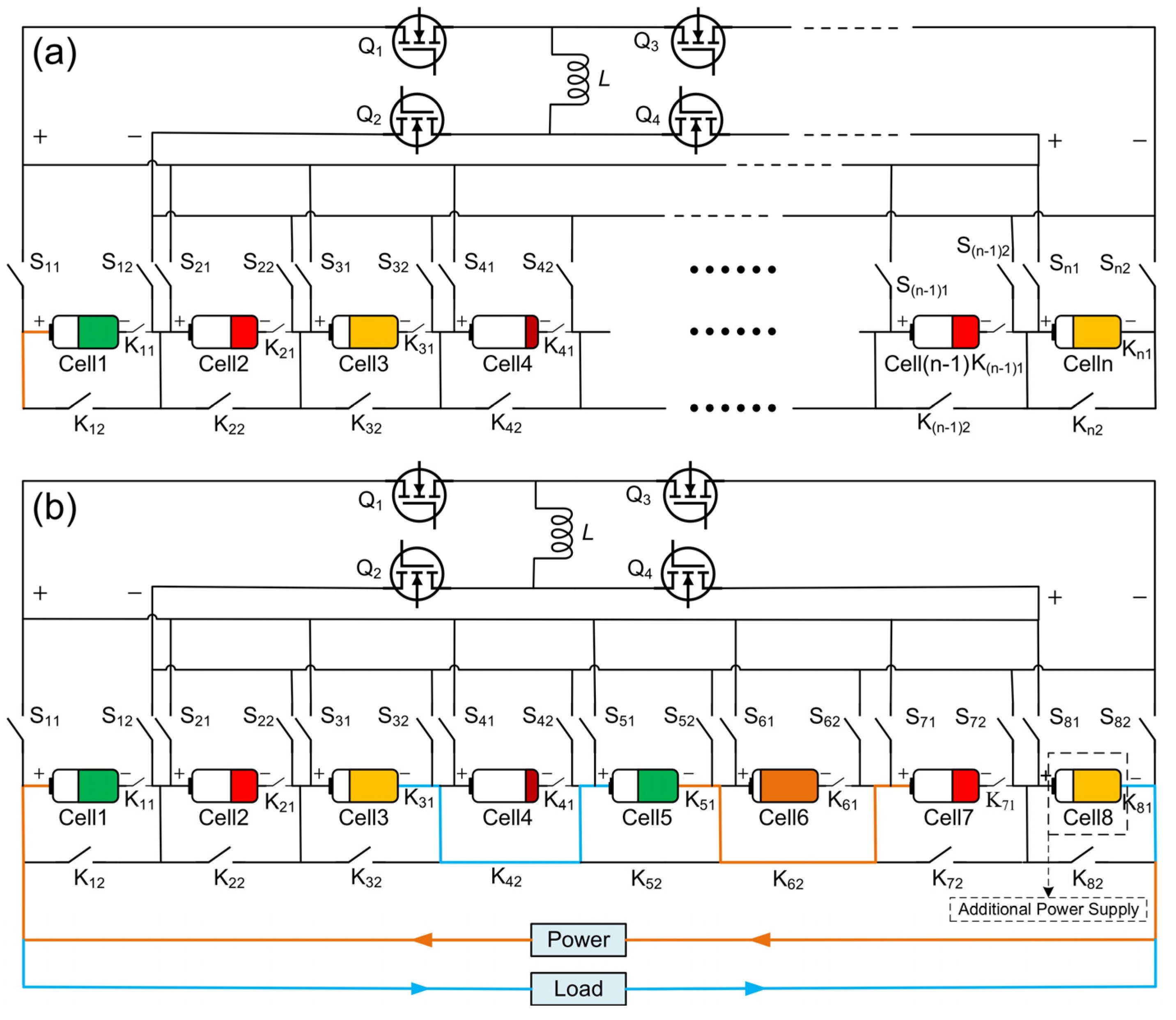
A balanced topology that combines reconfigurable circuits with Buck–Boost circuits (as shown in
Figure 1a) has been proposed. By controlling the switch array, this topology can dynamically combine series-connected battery packs to achieve multi-cell-to-multi-cell balancing. The main structure includes a reconfigurable circuit, a Buck–Boost active balancing circuit and a switch array. The switch array consists of positive electrode switches (S
11, S
21 ~ S
n1), negative electrode switches (S
12, S
22 ~ S
n2), and mutually exclusive switches (K
11, K
21 ~ K
n1; K
12, K
22 ~ K
n2; n represents the number of series-connected batteries) that are paired with each battery. The balancing circuit uses a non-isolated Buck–Boost circuit, whose components include an inductor (L) and MOSFETs (Q1 ~ Q4). The text illustrates a topology with eight batteries in
Figure 1b as an example. This topology has several advantages, including the ability to balance multiple batteries simultaneously, isolate faulty batteries, and reduce the number of energy transfers during the balancing process.
For batteries in a static state, regardless of the initial SOC distribution, adaptive grouping of non-adjacent batteries can be performed according to the balancing strategy. There are three working modes: balancing between any single cell to any other single cell, balancing between a group of multiple cells to a single cell, and balancing between multiple cells to multiple cells. In the charging and discharging mode of the battery, the balancing topology still has these three working modes. However, when performing balancing between multiple cells and multiple cells, the grouping method is based on adjacent cells.
2.2. State Space Model of Battery Dynamic Grouping Equalization System
In the circuit, the Buck–Boost balancing unit can achieve energy transfer between any batteries. Within a control period, the average current transferred by the balancing unit is defined as
Ie(0,
Iemax). Since there is only one balancer and the batteries are connected in series, the balancing current of the balancer is a scalar rather than a vector. The current for different batteries is limited according to the battery pack balancing topology matrix, with the direction defined as positive for charging and negative for discharging. To achieve the balance of SOC for each battery, when
Di(
k) > 0, energy should be transferred from battery Cell i to the balancing unit, and conversely, when
Di(
k) < 0, energy should be transferred from the balancing unit to battery Cell i. Here,
Di(
k) represents the optimal energy transfer direction of the battery pack in the topology, and
D is the matrix of the optimal energy transfer direction of the battery pack. In this section, vectors and matrices are represented in bold. The balancing current flowing through each battery during the balancing process is the following:
where
k represents the
k-th control period; α is the energy transfer efficiency of the balancer;
IeBi(
k) represents the equalization current flowing into the
i-th battery; and
kBi represents the Energy transfer direction state variable.
The current flowing from the equalizer to
n cells is expressed as follows:
where
represents the equalization current flowing from the equalizer to
n cells;
is the topology matrix of the equalization system.
In the equalization system, the total current
IBi(
k) of the
i-th battery includes the external operating current
ILoad(
k) of the battery pack and the equalization current
IeBi(
k) flowing into the
i-th battery. Kirchhoff’s current law is the following:
The SOC of the
i-th battery can be expressed as follows:
where
;
Qi is the capacity of the Cell
i;
represents the Coulomb efficiency; and
Ts is the sampling period.
The state variables and control inputs of the equilibrium system can be defined as follows:
The state space model of the equilibrium system can be derived as follows:
where
;
Q is the battery capacity matrix;
E is the identity matrix; and
In is a column vector with
n elements all being 1.
2.3. Dynamic Equalization Control Strategy MPC-Based
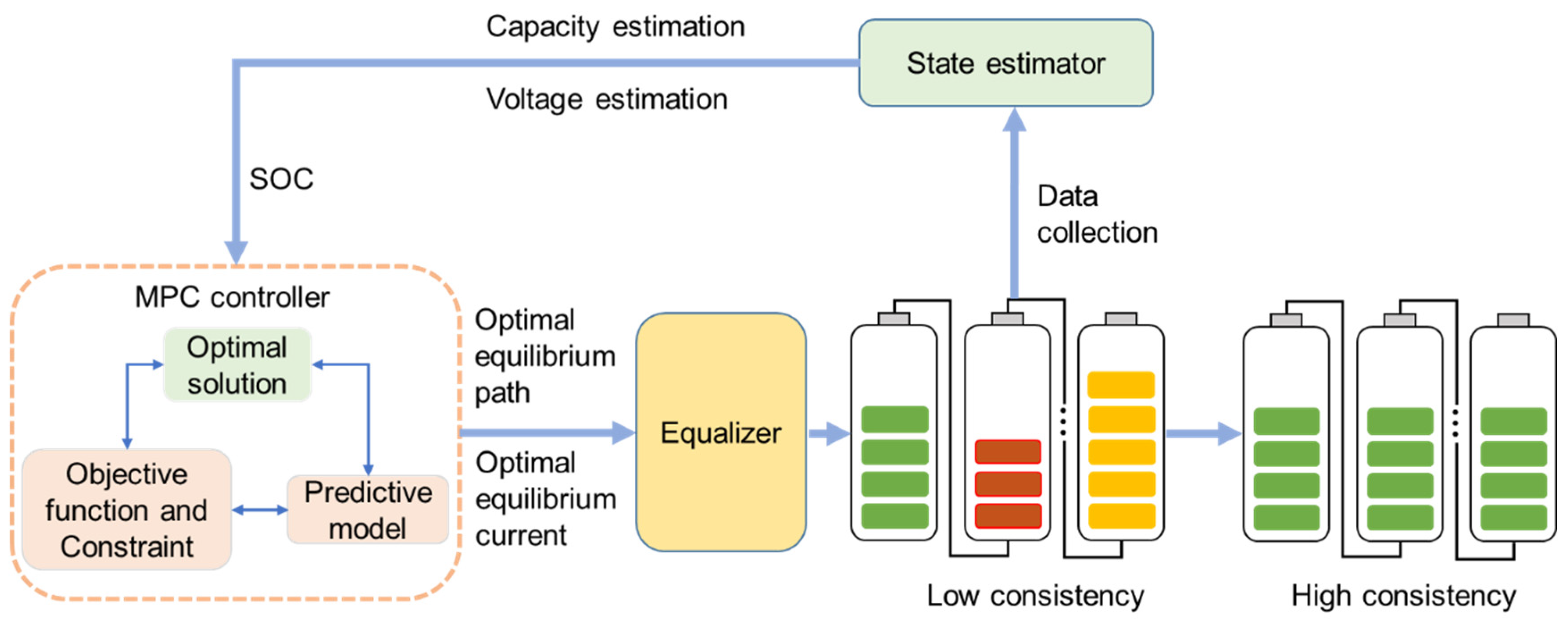
The MPC optimization method to control and constrain variables, such as the battery pack SOC, current, and voltage, was used. During the battery balancing management process, it achieves the design and solution of the optimal energy transfer direction and the optimal balancing current control algorithm for the battery pack. The principle of the balancing optimization control strategy is shown in
Figure 2. It mainly includes four parts: the battery pack, the battery state observer estimator, the MPC controller, and the battery pack balancer. The battery state estimator estimates the SOC of the battery based on the collected data, such as battery voltage and capacity, and transmits it as input to the MPC controller. The MPC controller, based on the battery pack SOC data, calculates the optimal energy transfer direction and the optimal balancing current under the preset objective function and constraints. Finally, the controller transmits the obtained control actions to the balancer, which converts the actions to be executed into a series of switch openings and closings, thereby achieving the optimal balancing control of the battery pack.
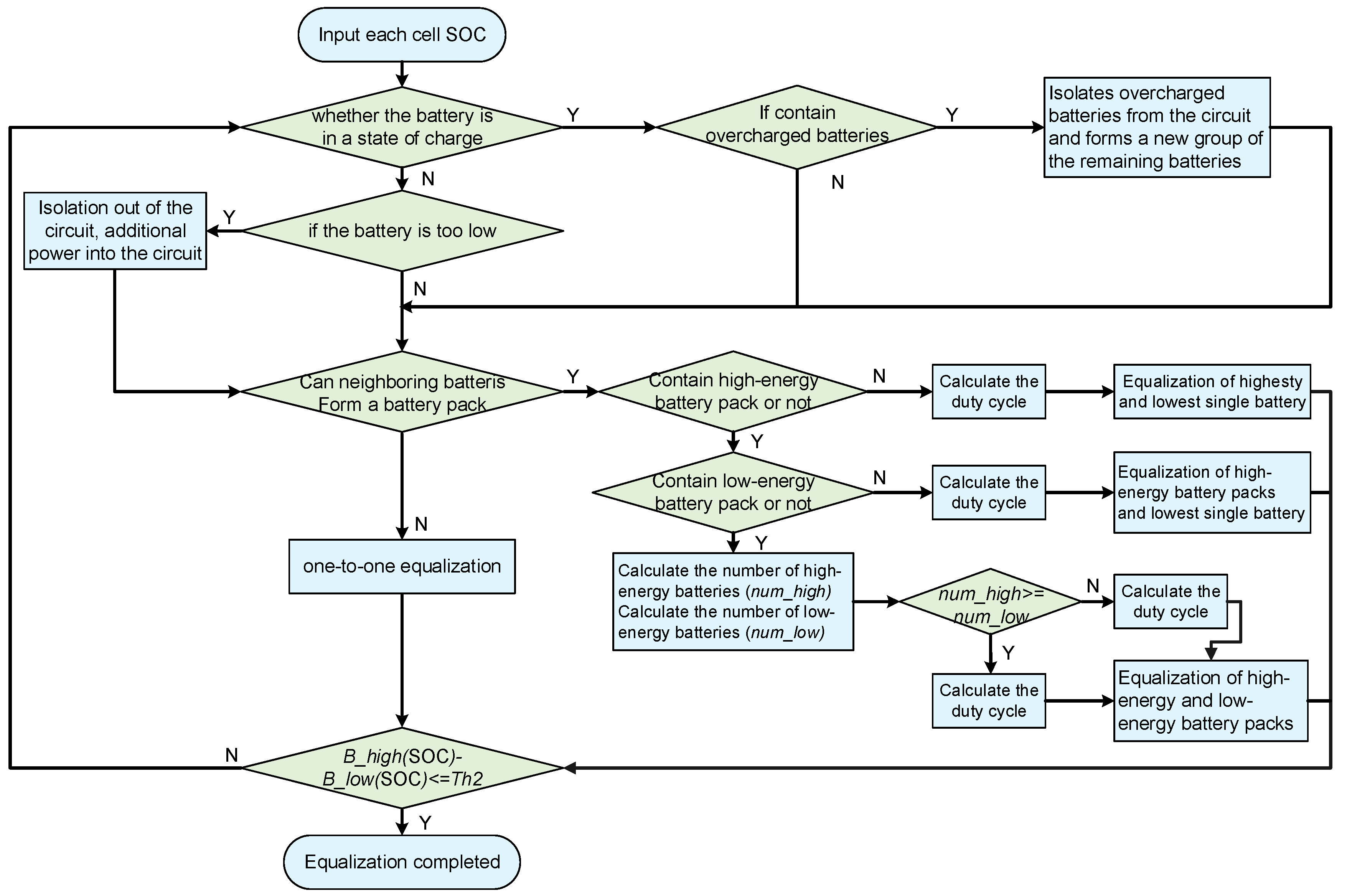
During the charging and discharging state of the battery pack, first determine whether there are any batteries with excessively high/low energy within the pack. If not, proceed directly to balancing. If there are, isolate them from the circuit and form a new group with the remaining batteries for balancing. During battery discharging, if a battery with low energy is isolated from the circuit, an additional power source is connected to the circuit to replace the isolated battery for discharging. The balancing control strategy is shown in
Figure 3.
2.4. Objective Function for Equalization Optimization
The equalization optimization aims to minimize the SOC difference, improve equalization speed, and reduce equalization energy loss. The equalization speed problem is transformed into solving a battery pack optimal energy transfer direction problem that can make the battery pack SOC reach the best consistency at the fastest speed in the future period. The objective function is the following:
where
N represents the prediction step size, and
and
represent the SOC of each battery and the mean vector of the SOC of the battery pack, respectively.
In addition, in order to reduce energy loss during the battery equalization process and suppress battery temperature rise, the energy loss problem is transformed into solving the optimal equalization current problem. The objective function is also considered on the basis of minimizing the SOC difference as follows:
To sum up, the objective function for the equilibrium strategy of the battery pack based on MPC is expressed as follows:
where
λ1 and
λ2 are weight coefficients, representing the relative importance of equilibrium time and energy loss, respectively. The selection of the weighting coefficients
λ1 and
λ2 is not an optimization process but rather a result of continuous trials to obtain a relatively better value. In practical situations, users can choose different weights according to their actual needs to achieve different goals. For example, to shorten the balancing time,
λ2 can be made smaller.
2.5. Constraints for Equalization Optimization
- (1)
Total current constraint of the battery
Generally speaking, the battery has been set to the maximum current value it can withstand when it is shipped from the factory. For the batteries selected herein, the maximum continuous discharge current is 5C, and the maximum charge current is 3C. In order to ensure the life and safety of the battery during operation, the total current constraint during the battery equalization process is the following:
where
Idis is the maximum discharge current of the battery;
Icha is the maximum charging current of the battery; and
u(
k) is the balancing current of the battery.
- (2)
Equalization current constraint of the battery
The electronic components in the equalization circuit are affected by manufacturing technology or cost, and there is an upper limit on the equalization current that can be provided. Therefore, in order to prevent the equalizer from burning out due to excessive equalization current during the equalization process, the constraints on the equalization current during the battery equalization process are the following:
where
Iemax is the upper limit of the current that the equalizer can provide.
2.6. Solution to Equalization Optimization
- (1)
Solution to the optimal equalization energy transfer direction
At this time, the battery pack equalization system state space model used to solve the optimal equalization energy transfer direction is the following [
21]:
is the optimal energy transfer direction matrix, ;
Here, the elements of matrix D can be interpreted as the necessity of charging and discharging a particular battery, which is recorded as
c.
c = 1 means that it must be discharged,
c = −1 means that it must be charged, and
c = 0 means that there is no need to charge and discharge. However, the obtained solution is a non-integer value between −1 and 1. Therefore, in order to more accurately control the charge and discharge of the battery, there are the following constraints:
With
, the state variables at
N moments in the future be iteratively calculated according to the state equation:
The vector form of predicted state variables is the following:
In order to better maintain the consistency of the battery pack SOC, the battery SOC state vector needs to satisfy the following relationship equation:
where
is the state vector of the SOC values of each cell;
is the state vector of the average SOC values of the battery pack; n is the number of cells; and
E is the unit matrix.
With
, there are further
. Then, the objective function to solve the optimal energy transfer direction of the battery pack is the following:
where
XkTLXk is a constant,
.
In order to use a general quadratic programming solver to solve the above quadratic programming optimization problem, the above problem of solving the optimal energy transfer direction of the battery pack is reconstructed into a standard form of quadratic programming problem as follows:
where
R represents the decision variable to be solved;
is a symmetric positive semi-definite matrix; and
is the coefficient matrix of linear terms.
The constraints are the following:
where
In×N is a matrix with elements all being 1.
- (2)
Solution to the optimal equalization of energy loss
Because the energy transfer efficiency α of the equalizer must be considered, the item with an element of −1 in the optimal energy transfer direction matrix D is multiplied by α, which represents the current flowing from the equalizer to the battery. The energy transfer efficiency of the equalizer must be considered: α < 1. From this, the equalization topology matrix kB of the battery pack can be obtained.
At this time, the battery pack equalization system state space model used to solve the optimal equalization energy loss is the following:
With
, the state variables at
N moments in the future be iteratively calculated according to the state equation:
The vector form of predicted state variables is the following:
where the following is true:
The control goal of this section is to achieve a better balance between the battery pack equalization time and energy loss. The objective function for solving the optimal equalization current is organized as follows:
At this point, the objective function can be transformed into a matrix form:
The above problem of solving the optimal energy transfer direction of the battery pack is reconstructed into a standard form of quadratic programming problem as the follows:
where
U represents the decision variable to be solved;
is a symmetric positive semi-definite matrix; and
is the coefficient matrix of linear terms.
The constraints are the following:
The dynamic nature of lithium-ion power batteries and the instability of the operating environment limit the accuracy of long-term predictive control. In the short term, the behavior and external conditions of the system are relatively easy to predict and control. But as the prediction and control time domains increase, so does the uncertainty. Therefore, in order to reduce the amount of computation and improve the response speed of the equalization system, the prediction time domain is set to 5, and the control time domain is set to 1.
Based on the inductor’s equalization current expression, the resulting optimal equalization current is converted to the duty cycle of the PWM generator controlling the switching devices [
24,
25]. The MPC-based battery pack equalization optimization control strategy is realized by controlling the switching arrays in the battery equalization topology.
2.7. Simulation Model for Equalization Optimization
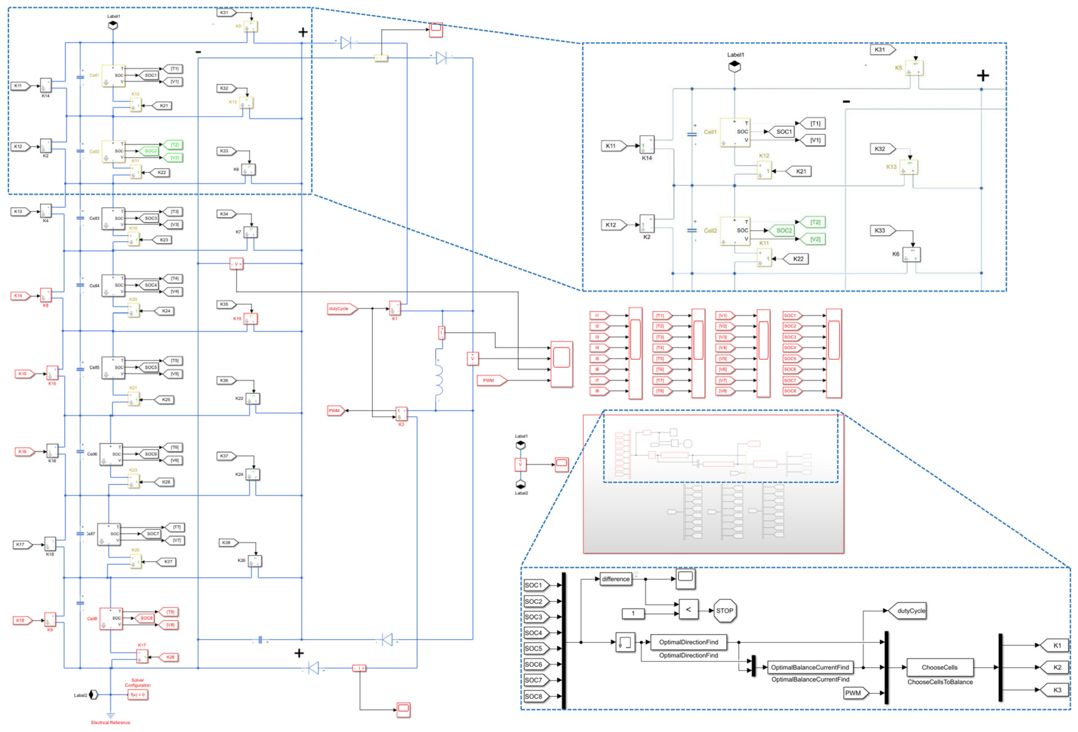
A battery pack equalization control strategy simulation model is established in Simulink, as shown in
Figure 4. It consists of three parts, namely the optimal energy transfer direction solution module of the battery pack, the optimal equalization current solution module and the battery switch control module.
Eight batteries were selected for simulation verification. The battery capacity is 20 Ah. The maximum equalization current and energy transfer efficiency of the equalizer in the equalization circuit are set to 20 A and 0.9, respectively; the sampling period is Ts = 1 s, and each PWM cycle is simulated in 25 steps. In order to verify the effectiveness of the proposed equalization strategy, simulation comparisons were made. The extreme tolerance range (SOCmax − SOCmin) of the equalization results is set to 1%. The relationship data between battery temperature and SOC was obtained through parameter identification at 5, 15, 25, 35, and 45 °C.
2.8. Weight Coefficient Selection of Equilibrium Optimization Model
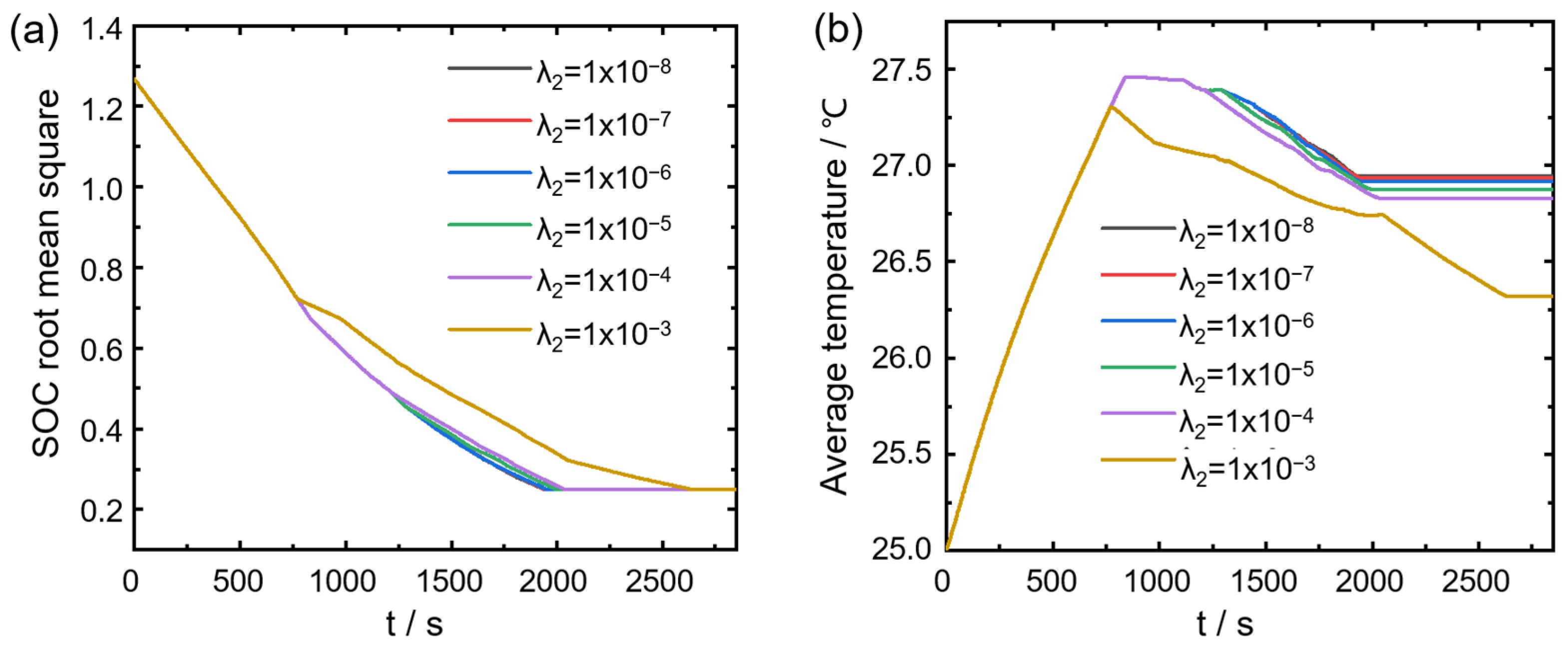
In the equilibrium optimization model, the weight coefficients, respectively, represent the relative importance of battery equalization time and energy loss during the equalization process. In order to evaluate the impact of weight coefficients on the performance of the battery equalization system, simulation tests under different weight coefficients were conducted in this section. Among them, λ
1 = 1 is fixed, λ
2 takes different values, and the initial SOC of each battery cell is set to 46.5%, 44.1%, 45.9%, 42.8%, 45.5%, 44.5%, 43.1%, and 45.7%, respectively.
Figure 5a,b shows the changes in battery pack SOC root mean square and battery pack average temperature with equalization time under different weight coefficients.
A larger λ2 suppresses the temperature rise of the battery pack but increases the equalization time. When λ2 = 1 × 10⁻³, the battery pack equalization time increases by 36.09% compared with when λ2 = 1 × 10⁻⁸, and the battery pack average maximum temperature value decreases by 1.68%, and the average temperature of the battery pack decreased by 2.41% when equalization was completed. In actual situations, users can choose appropriate weights based on this conclusion to balance the relationship between equalization time and energy loss. It can be seen from the figure that λ2 = 1 × 10⁻⁴ better balances these two conflicting goals. Therefore, this article selects this weight for subsequent simulation analysis.
3. The Results and Discussions
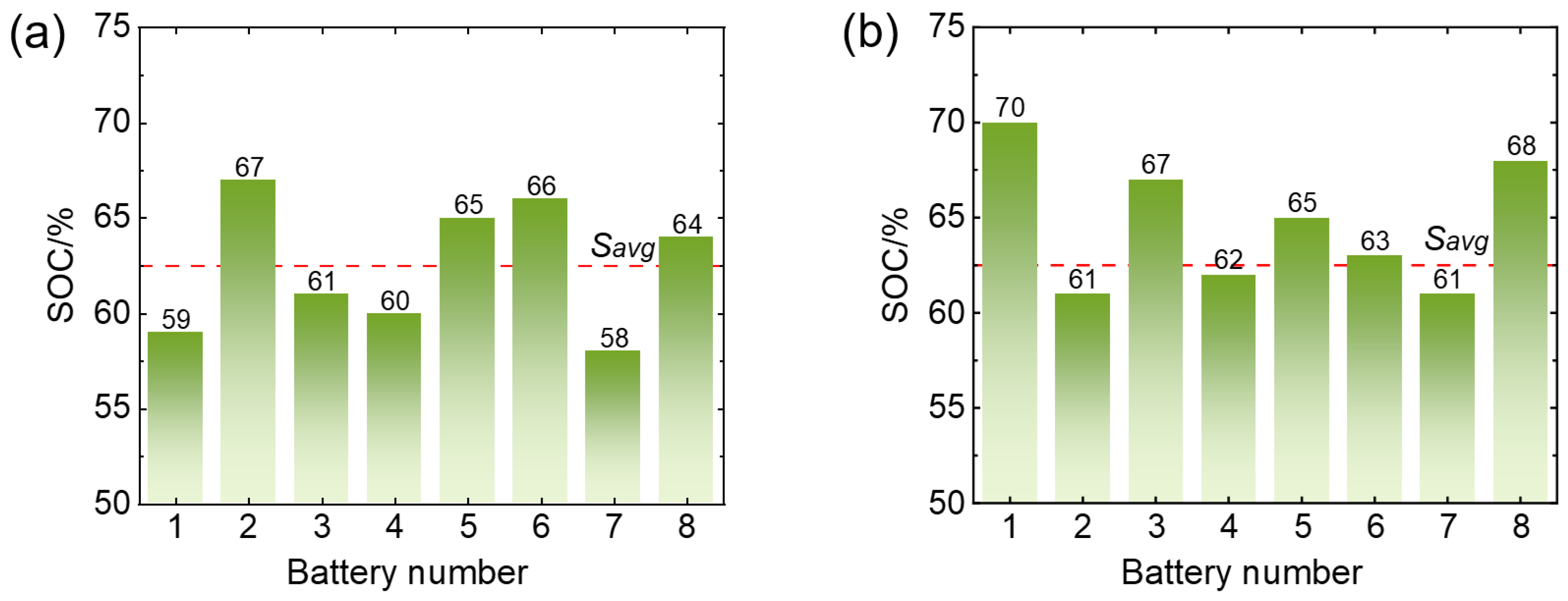
In order to make the simulation experiment fair, two sets of the SOC of eight single cells in the unbalanced series battery pack are randomly generated (
Figure 6). The single-cell SOC polarity (SOC
max − SOC
min) is 9%.
- (1)
Fixed grouping equalization simulation analysis
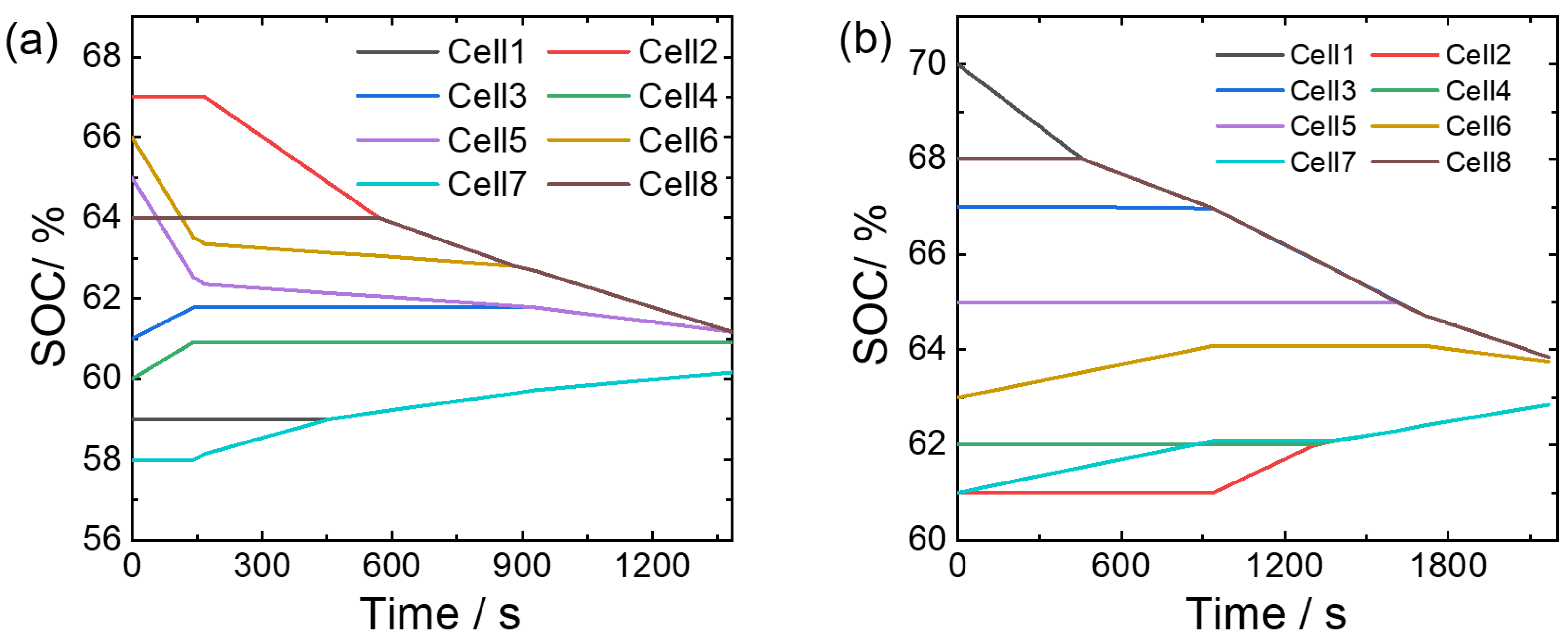
The fixed group equilibrium strategy refers to the grouping of batteries limited to adjacent batteries. The simulation results using a fixed group equilibrium strategy are shown in
Figure 7a, with a total balancing time of 1384.55 s. After balancing, the SOC of each individual battery is 60.48%, 61.48%, 61.43%, 60.77%, 61.43%, 61.48%, 60.48%, and 61.48%, with a variance of 0.1788. Similar results also appeared in the second group.
It can be observed that at the beginning of equalization, due to the uneven distribution of batteries, only four batteries participated in the equalization. Moreover, the energy distribution of the battery pack at this time is just so that adjacent cells can form a battery cluster. In actual use, due to the uneven energy distribution of the battery pack, if the battery power is arranged alternately between high and low, then only cell-to-cell equalization mode can be used, which will cause the equilibrium time to increase significantly.
- (2)
Dynamic grouping equalization simulation analysis
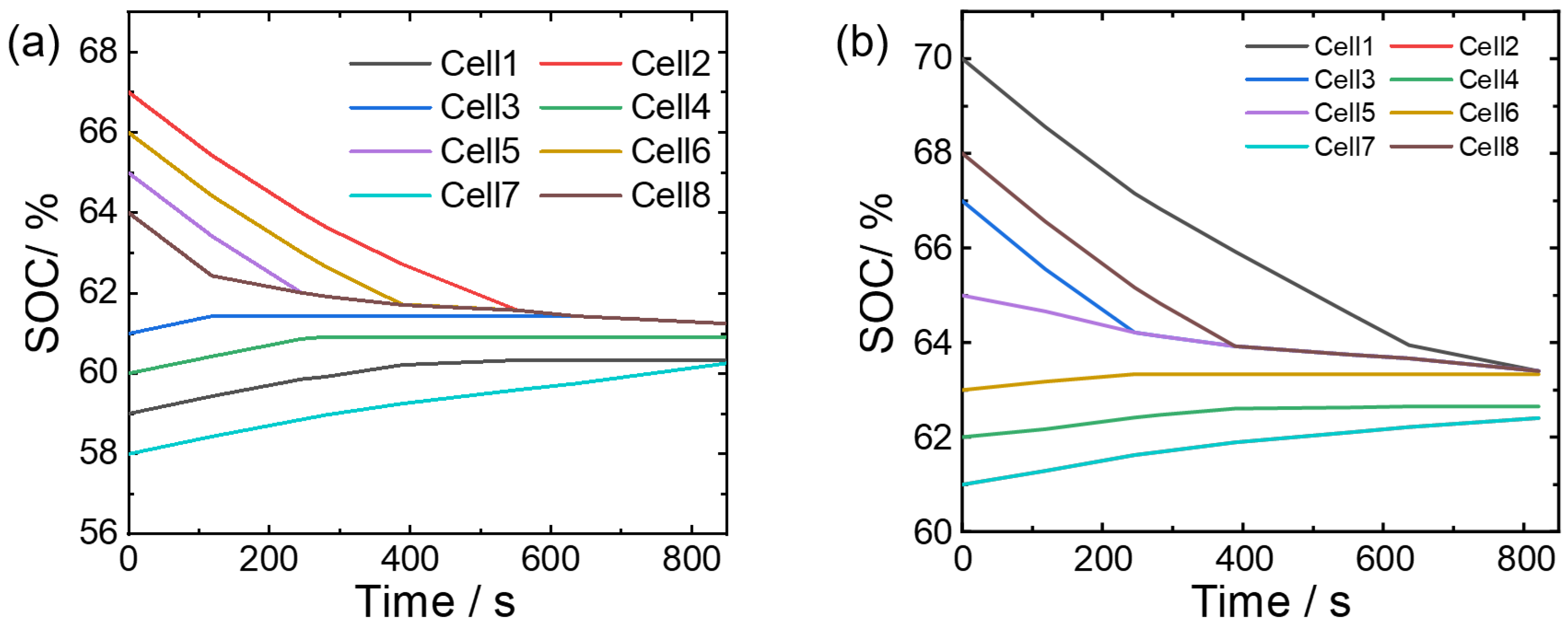
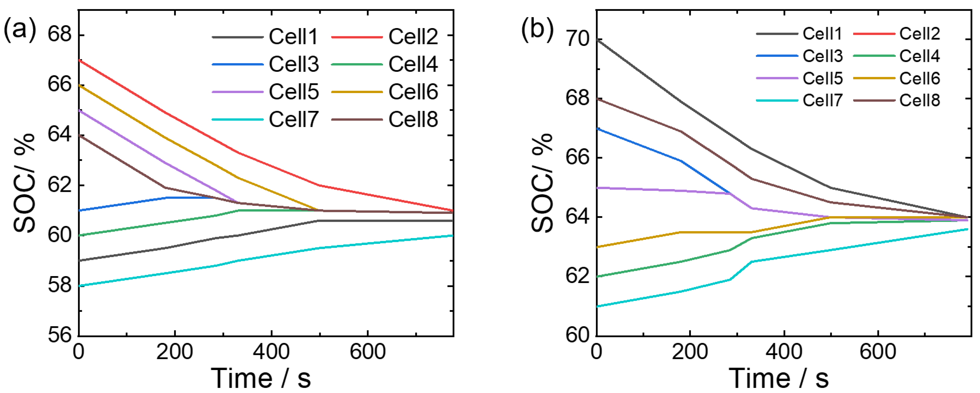
The dynamic grouping equilibrium strategy refers to the group of batteries that can be performed between non-adjacent batteries. The simulation results are shown in
Figure 8a, with a total balancing time of 850.18 s. After balancing, the SOC of each individual battery is 60.33%, 61.16%, 61.16%, 60.92%, 61.16%, 61.16%, 60.16%, and 61.16%, with a variance of 0.1653. Approximate variations also occurred in the initial SOC values of the second group (
Figure 8b). All eight batteries participate in the equalization at the beginning of equalization. As the equalization progresses, the batteries with SOC close to the average SOC of the battery pack will exit the equalization until the equalization ends. This equalization method has better applicability for the actual use process.
- (3)
Analysis of equalization simulation MPC-based
The equilibrium strategy based on MPC considers the optimal direction of energy transfer and the optimal equilibrium current on the basis of dynamic grouping. The selected direction of energy transfer can enable the energy of the battery pack to be transmitted in the fastest and most consistent direction in the future.
Figure 9a shows the simulation results using the MPC equalization strategy. The total equalization time is 776.26s. After the equalization is completed, the SOC of each single cell is 60.6%, 61%, 60.9%, 60.9%, 60.9%, 60.9%, 60% and 60.9%, with a variance of 0.0948. The second group also exhibits similar patterns (
Figure 9b).
A comparison of the three equalization simulation results is shown in
Table 1. It can be seen that compared with the fixed group equalization strategy, the dynamic group equalization strategy reduces the equalization time by 38.6%. After equalization is completed, the battery pack SOC variance is reduced by 20.44%. Due to the shortened equalization time, the energy transfer efficiency is improved by 0.37%. However, the battery pack equalization strategy based on MPC selects the best energy transfer direction and can dynamically calculate the equalization current, so the equalization time is reduced by 43.93%, and the battery pack SOC variance is reduced by 50.18% after equalization is completed. The energy transfer efficiency is improved by 0.59%. It can be seen that the equalization strategy MPC-based reduces equalization time and improves consistency and energy utilization of the battery pack. Therefore, the comparison of three sets of simulation results verifies the effectiveness of the proposed equilibrium strategy.
For battery packs with a relatively large number of cells, different levels of high and low-energy cells are randomly distributed. All high-energy cells and all low-energy cells need to be dynamically grouped for equalization. Therefore, how to select batteries for equalization is extremely important for the equalization results. The advantages of the equalization strategy, considering the optimal direction of energy transfer and the optimal equilibrium current based on dynamic grouping, will be more prominent.
The balancing simulation results of the two groups show a consistent situation. It is worth noting that in the fixed grouping simulation, since the SOC distribution of the second group does not allow adjacent batteries to be grouped for balancing at the beginning of the balancing process, the increase in balancing time is relatively large compared to the first group. However, both dynamic grouping and MPC-based balancing can achieve grouping of non-adjacent batteries for balancing, so the simulation time difference corresponding to the two groups of SOC is not significant. We analyze the effectiveness of different balancing strategies based on the simulation results of the first group of SOC. The results are shown in
Table 1.
4. Conclusions
This work addresses the issues of equalization speed and energy loss in lithium battery management by developing a dynamic group equalization topology and an optimization model focused on optimal energy transfer direction and loss reduction. A dynamic equalization topology, combining reconfigurable and Buck–Boost circuits, reduces equalization times and energy loss and boosts speed. An MPC-based optimization method controls battery pack SOC and current, achieving optimal energy transfer and current control. Selecting appropriate weight coefficients balances equalization time and energy loss, ensuring faster, more efficient SOC consistency. Compared with the fixed grouping balancing strategy, the dynamic grouping balancing strategy reduces the balancing time by 38.6%, decreases the variance of the battery pack SOC by 20.44% after balancing is completed, and slightly decreases the energy transfer efficiency by 0.36%. Compared with the dynamic grouping balancing strategy, the MPC-based battery pack balancing strategy, which selects the optimal energy transfer direction and can dynamically calculate the balancing current, reduces the balancing time by 8.7%, decreases the variance of the battery pack SOC by 37.38% after balancing is completed, and slightly decreases the energy transfer efficiency by 0.22%. The results show the MPC-based strategy outperforms dynamic grouping in SOC consistency and speed, with slightly lower energy loss. For large battery packs, its speed advantage is more evident.


