Abstract
Due to the complementary operational features, photovoltaic (PV) and fuel cell (FC) systems are increasingly being integrated into hybrid microgrids. PV systems provide clean energy during the day, while FCs provide continuous power supply throughout the day and night; thus, FCs can address PV’s incapacity during the night. However, voltage instability, frequency deviation, and enhanced harmonic distortion can result from the intrinsic intermittency of solar energy, switching errors in power electronic equipment, and varying load demands. Thus, a fuzzy logic-based current-controlled voltage source inverter (CC-VSI) is proposed in this paper to overcome these issues and enhance power quality in PV-FC hybrid microgrids. As per IEEE 1547 regulations, the fuzzy controller dynamically modifies the inverter current to maintain steady voltage and frequency profiles. MATLAB/Simulink (R2022a) is used to model and simulate the system, and its performance is evaluated under various reactive load scenarios. To test the efficacy of the proposed control technique, various power quality metrics, viz., voltage profiles (sag and swell), frequency profile, and total harmonic distortions, are plotted when subjected to large reactive load variations. The simulation results that are obtained with the proposed fuzzy-based current control technique are compared with the conventional artificial neural networks-based controller to verify the effectiveness. From the comparison study, it is found that the proposed technique shows superior power quality performance over the conventional technique. This encourages the development of renewable energy-based sustainable hybrid microgrids worldwide.
1. Introduction
A microgrid is a small-scale, decentralized energy system that provides a flexible and effective method of generating, distributing, and consuming power. Fundamentally, a microgrid is a small-sized and self-sufficient power system that can function both separately and in tandem with the wider grid network. In addition to energy storage devices like batteries, microgrids are made up of a variety of distributed energy resources (DERs), such as non-renewable sources like fuel cells (FCs) and diesel generators and renewable sources like solar panels and wind turbines [1,2]. As the world’s energy needs increase and the shift to cleaner energy continues, the hybrid integration of various sources in microgrids offers a workable way to achieve dependable and sustainable power generation and delivery [3]. However, amid the advancements in leveraging diverse renewable resources, the issue of power quality surfaces as a critical challenge that demands immediate attention. The need to solve power quality issues in hybrid renewable energy-based microgrids arises from the inherent characteristics of renewable energy sources. Wind and solar power, for instance, are inherently intermittent, subject to variations due to weather conditions, time of day, or seasonality. Such fluctuations in energy output can directly impact voltage levels, frequency stability, and overall power quality within the microgrid [4]. Additionally, the integration of multiple energy sources in hybrid systems brings forth synchronization challenges and potential conflicts in voltage regulation and phase balancing. These issues can lead to harmonic distortions, voltage fluctuations, and imbalances, adversely affecting the quality of power delivered to end-users and sensitive electrical equipment. Moreover, because these microgrids frequently function in isolated or off-grid areas, the necessity of upholding strict power quality requirements is made more critical by the lack of a reliable connection to a centralized grid. To ensure consistent and high-quality power output, advanced control systems, smart inverters, energy storage, predictive algorithms, etc., are essential for controlling voltage, frequency, and harmonics [5].
1.1. Background and Motivation
Multiple energy sources are used in hybrid microgrids to improve power quality, flexibility, and dependability. Because of their complementing qualities, integrating photovoltaic (PV) panels with proton exchange membrane fuel cells (PEMFCs) offers a promising architecture, among other combinations: whereas FCs provide a steady and dispatchable energy output, PV systems deliver sporadic electricity that is affected by irradiance. However, there are serious power quality issues when connecting these sources to the electric grid. Voltage sags, swells, frequency deviations, and harmonic distortions are caused by variations in load conditions, nonlinear switching behavior of inverters, and fluctuations in irradiance. Both local and grid loads may be impacted by these disruptions when they spread to the point of common coupling (PCC). Conventional PI or ANN-based current controllers, which may not provide enough flexibility in extremely dynamic settings, are frequently the basis of traditional control systems. This restriction highlights the need for clever, rule-based control strategies that can more successfully manage uncertainties and nonlinearities in hybrid renewable systems. In this regard, we proposed a current-controlled voltage source inverter (CC-VSI) based on fuzzy logic that is designed for a PV-FC hybrid microgrid. To improve power quality metrics including voltage profile stability, frequency regulation, and total harmonic distortion (THD) suppression, the fuzzy controller is made to control inverter current corresponding to grid voltage and frequency aberrations. This study compares the performance of a traditional ANN-based controller with the suggested fuzzy-based CC-VSI under dynamic loading situations in a grid-connected scenario.
1.2. Literature Works
The detailed works carried out by the researchers so far are discussed as follows. In [6], the authors developed an artificial neural network (ANN), which controls a single-phase inverter and is also used to integrate the residential photovoltaic system into the utility grid. Later, in [7], the authors proposed a study to construct a wind energy conversion system that will be fed into the unified power quality controller (UPQC)’s dc-link capacitor to maintain an appropriate voltage across it and run the UPQC to improve power quality. A combined ant lion optimizer-adaptive neuro-fuzzy inference system is employed to improve UPQC performance. However, reference [8] discussed an inverter control which includes a variety of sliding mode control approaches to govern the reactive and true power flow among the load, renewable energy plant, and grid. The modified shrinkage broadly linear complex-valued least mean squares technique for grid-interfaced microgrids based on photovoltaic–wind power generating systems is proposed in [9]. The work in [10] aims to investigate the harmonic response of hybrid microgrids. Improved harmonics of the AC portion of the system have been attained through the employment of a power filter compensator along with a refined active power filter. However, various optimization algorithms are used to optimize the controller gain coefficients. Later, the authors in [11] used a new modulated UPQC for enhancing the quality of operation factors in a stand-alone hybrid microgrid using different well-known optimization techniques. However, the authors in [12] presented an energy management scheme for the efficient functioning of microgrids and introduced artificial intelligence controllers to maintain the microgrid’s stability.
For more intelligent grid-integrated power systems, an artificial intelligence-based IcosØ control method for power quality enhancement and power sharing in microgrid plants is presented [13]. The suggested controller considers several variables, including those carried on by variations in demand, the battery life of microgrids, and energy tariffs that are dependent on the accessibility of electricity in microgrids. Later, in [14], the authors introduced a controller for a solar photovoltaic-based cascaded multilevel inverter using an ANN. This controller aims to achieve the highest possible output voltage without the need for filter elements. This study also uses a variety of methods to remove voltage harmonics that happened in a solar-based cascaded three-stage inverter. The study in [15] aims to develop a harmonic compensation method suitable for hybrid DC-AC interlinking converters with reduced switching frequencies and also discusses the proposed approach, modeling methodologies, stability analysis, and a comprehensive virtual impedance design. Similarly, studies in [16,17,18] discussed and reviewed the applications of machine learning and artificial intelligence methods that are used to integrate renewable energy sources into the grid and also to maintain the power quality in grid-integrated microgrids. As a resolution to power quality improvement, some studies are developing new control strategies for multi-level inverters. To improve power quality [19], an ANN-based controller [20] is suggested for a solar photovoltaic-fed cascaded multilevel inverter using an ANN. This ANN controller’s goal is to achieve the highest output voltage without the need for any filter components. The authors in [21] suggested a hybrid grid-connected photovoltaic system that combines heap-based optimizers and the Lichtenberg optimization method. The suggested approach enhances the system’s power quality and efficiency and realizes a multifunctional operation in conjunction with the interleaved inverter. The THD and voltage sag in a solar–wind microgrid, a combination of a fuzzy and pulse-width modulation (PWM) inverter with a superconducting fault current limiter, is introduced in [22]. Under changing renewable inputs, their MATLAB/Simulink simulation findings show THD reductions of approximately 4.5% to 2.3%, underscoring the advantage of combining FLC with SFCL for improved ride-through capabilities. For a PV inverter, a fuzzy sliding-mode control (FSMC) with an adaptive exponential reaching rule has been introduced in reference [23]. This method adaptively adjusts sliding-mode gains to reduce chattering and improve resilience to irradiance variations; Simulink experiments provide <1% steady-state error under 50% load steps, and Lyapunov-based proofs validate system stability. A genetic algorithm (GA) is used to optimize the membership parameters of a fractional-order Type-2 FLC developed in [24]. When used in a PV–battery microgrid, the GA-T2FLC outperforms traditional FO controllers in terms of frequency stability and dynamic response (settling time < 40 ms).
From the above literature, it is understood that the researchers are eager to identify and develop useful solutions for enhancing the performance of microgrids in terms of power quality, energy management, efficiency, etc. However, in most cases, a single solar PV source, wind source, or a combination of both are considered, which are usually unpredictable due to their dependency on weather conditions. In any case, solar power is unavailable at night. Thus, the hybrid system needs to be equipped with other sources, such as PEMFCs, to perform beyond these built-in limitations. In view of all these drawbacks, this paper proposes the following contributions.
- ▪
- To form a PV-FC hybrid microgrid that allows for bidirectional power exchange with the utility grid to maintain power balance under changing generation and load situations and whose output can be dynamically modified by modifying the PEMFC output power.
- ▪
- To develop a fuzzy-based current controller for the voltage source inverter of the hybrid microgrid to improve the power quality at the consumer end.
- ▪
- To study all the power quality improvement through the computation of indices such as, namely, voltage profile (sag and swell), frequency profile, total harmonic distortion (THD), and also the power factor of the proposed hybrid microgrid system.
The rest of this paper is structured as follows. The description of the PV-FC-based hybrid microgrid and its associated constituents is given in Section 2. Section 3 discusses the development of the proposed fuzzy-based current-controlled voltage source inverter. Section 4 discusses the simulation findings, and Section 5 concludes the outcomes.
2. Description of PV-FC-Based Hybrid Microgrid
An architectural view of the grid-connected hybrid microgrid formed by integrating fuzzy controller-tuned MPPT-based PV and FC sources is depicted in Figure 1. Both the energy sources are modeled as nonlinear voltage sources in this work, which are detailed in the following subsections. The voltage obtained from these sources is not constant and not able to meet the desired load demands, i.e., the AC load connected to the PCC of the microgrid. So, a boost converter is required to boost up the voltage to a required level at its output. Both the sources are fed to a common DC bus which produces a fixed DC voltage of 500 V and is now applied as input to a three-phase voltage source inverter. The output of the voltage source inverter is now filtered using an LCL filter and is connected to the utility grid via the 100 MVA three-phase transformers. The voltage source inverter control loop uses a fuzzy logic-based current controller to control the inverter output by producing switching pulses in response to changes in load circumstances, voltage, and frequency. A phasor generation module, DC voltage regulator, and phase-locked loop (PLL) are all part of the control system. An ANN-based current controller is also modeled for comparison.
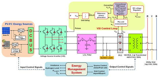
Figure 1.
Schematic of PV-FC hybrid microgrid under grid-connected mode.
To guarantee coordinated power injection and grid compliance, the energy management system (EMS) continuously modifies control signals in response to input factors like irradiance and hydrogen levels. With important metrics assessed later in the simulation analysis, this integrated control and power structure is intended to enhance power quality throughout a range of operating situations. To capture the nonlinear dynamics brought about by power electronic interface and control mechanisms under various load and generation scenarios, both the PV and FC energy sources are denoted as nonlinear voltage sources in this work. This is not because of their intrinsic electrical characteristics.
2.1. Modeling of Solar PV Array
The solar PV subsystem configuration employed in this work is shown in Figure 2. The PV array’s output characteristics, voltage Vsol, and current Isol are continuously monitored while it runs in dynamic temperature and irradiance circumstances. The ideal duty cycle for the DC–DC converter is found by feeding these into an MPPT algorithm that uses fuzzy logic. This method increases the efficiency of energy collecting and improves tracking performance under fast environmental changes. After that, the converter’s output is fed into the microgrid system’s shared DC bus.
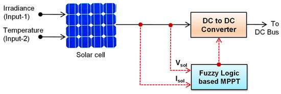
Figure 2.
Block diagram of solar PV system.
In general, due to the straightforward feedback structure and a small number of observed parameters, the perturb and observation (P&O) method is gaining popularity for implementing the maximum power point tracking (MPPT) control when compared with other algorithms such as incremental conductance, and constant voltage. However, these conventional methods are limited to linear system variations. So, this work implements a fuzzy logic-based MPPT that can satisfactorily address the nonlinear parametric variations. This paper uses the single-diode model (SDM), which is the most widely adopted circuit-based model for PV cells, despite the existence of various other modeling techniques. While the double-diode model provides greater accuracy, especially by accounting for recombination losses in the space-charge region, it also introduces additional computational complexity. Although double-diode and triple-diode models offer certain advantages, the inclusion of extra diodes increases the model’s complexity. The SDM, therefore, is generally considered to provide a good trade-off between accuracy and simplicity. This likely explains its widespread use, particularly given the complex dependence of electric current on environmental and weather-related parameters such as ambient temperature (T) and irradiance (G). The mathematical modeling of the PV module for one diode model is expressed using Equations (1) and (2) [25].
where —solar current; —reverse saturation current; —light generated current; —elementary charge; —terminal voltage of cell; —diode’s ideality factor; —Boltzmann’s parameter; —solar temperature in Kelvin; —series resistance; —parallel resistance; —solar irradiance; and —area of the solar cell.
2.2. Fuzzy Logic-Based MPPT Control
Fuzzy logic controllers can effectively manage nonlinearity, operate with imprecise inputs, and do not require perfect mathematical models. Change in power and change in current are the two inputs given to the fuzzy controller at a sampling instant of time n (seconds), and the output is . Corresponding error E(n) and change in error ∆E(n) signals are given by Equations (3) and (4).
where and are the power and current of the solar PV module. Table 1 shows the fuzzy rules chosen to obtain the desired output from the fuzzy-based MPPT controller. There are a total of five membership functions, i.e., Low (L), Very Low (VL), Zero (Z), High (H), and Very High (VH), that are considered. Figure 3 illustrates the pseudo color plot for the membership functions developed for the MPPT algorithm, inspired by methodologies discussed in [26]. The corresponding I-V and P-V characteristics of the solar system with an MPPT controller are shown in Figure 4.

Table 1.
Fuzzy rules designed for MPPT controller.
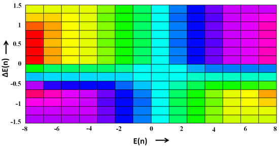
Figure 3.
The pseudo color plot of the fuzzy logic controller.
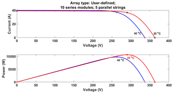
Figure 4.
Characteristics of the solar PV system.
2.3. Modeling of PEM Fuel Cell
The PEMFC system’s structure used to form the hybrid microgrid is shown in Figure 5. The FC uses the electrochemical reaction between hydrogen and oxygen to produce a DC voltage output. The PWM is used in a closed-loop control system to modulate the duty cycle of the related DC-DC converter.
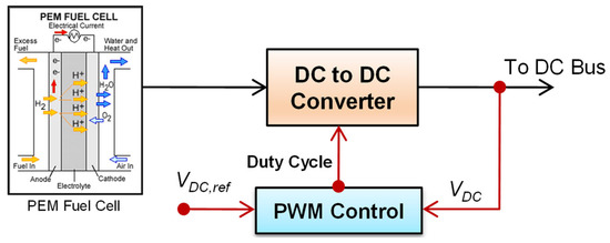
Figure 5.
Block diagram of PEM fuel cell.
To stabilize the power delivered to the DC bus, the controller compares the actual output voltage, Vdc, with a predetermined reference voltage, Vdc,Ref. This guarantees the FC source’s successful integration with the microgrids and other renewable units. Simulink modeling of a PEMFC entails simulating the many physical and electrochemical reactions that take place inside the FC. In this, we considered a simple model rather than the actual model due to its complexity. The mathematical modeling of the PEMFC is given in Equations (5) and (6) [25]. The detailed modeling of the DC to DC boost converter and DC bus used in this work is adapted from [27].
where is the EMF of the FC; F and R are the Faraday’s and gas constants; I and V are the current and voltage of the FC; T is the temperature in Kelvin; n is the number of electrons transferred in the chemical reactions; A is the electrode area; and are the concentration of hydrogen at outlet and inlet, respectively.
2.4. Energy Management System of Solar PV-FC-Based Hybrid Power System
To operate a PV-FC-based hybrid power system as efficiently, reliably, and optimally as possible, an energy management system (EMS) must be necessary. Without EMS, the system may experience energy waste, instability, increased operating costs, and shortened component lifespans. Figure 6 shows the flow-chart representation for implementing the EMS in the Simulink software. The EMS shown in this figure calculates the PV power (PPV) after the MPPT algorithm and checks whether PPV is greater than the load demand (PD) or not. If the solar power itself is sufficient to deliver the load demand, then there is no need for FC power.
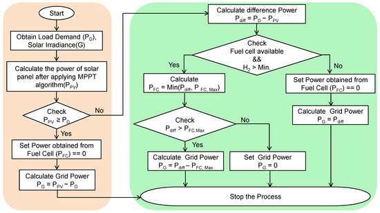
Figure 6.
Flowchart of energy management system for the proposed hybrid microgrid.
The grid power is calculated as given in Equation (7). If the solar power is not sufficient to deliver the load, then the difference in power requirement is calculated using Equation (8). The EMS will check whether the FC is available or not; if not, then the same power can be imported from the grid. If the FC is available, then utilize it to make up as much of the power shortfall as we can while staying within its rated maximum capacity as shown in Equation (9). EMS again checks whether the Pdiff is greater than PFC,Max; if it is yes, then calculate the grid power as given in Equation (10), or else EMS will consider the FC power as sufficient.
3. Fuzzy-Based Current-Controlled Voltage Source Inverter
Current controllers of voltage source inverters based on fuzzy logic are made to offer a control scheme that can manage the uncertainties and nonlinearities that are frequently seen in power electronic systems. Fuzzy logic controllers are especially well-suited for situations where accurate mathematical modeling is difficult since they make control decisions using linguistic variables and rules. Similarly, fuzzy logic controllers have an advantage over standard control methods in situations where complicated and nonlinear dynamics are present. This is because fuzzy logic controllers may capture and utilize expert knowledge in the form of language rules. Even in the face of shifting operating conditions or disruptions, the voltage source inverter’s output current is intended to be effectively regulated by the fuzzy logic-based current controller. Fuzzy logic control is developed by using the fuzzy set theory discussed by Zadeh in 1965. The transition between membership and non-membership functions is derived from the fuzzy logic notion. Since fuzzy sets’ borders might be ill-defined and unclear, approximation systems can benefit from them. When using exact mathematical formulas is not feasible, fuzzy logic controllers are a desirable option. The block diagram representation of the proposed fuzzy-based current controller for controlling the voltage source inverter is shown in Figure 7. Various constituents of this model implemented in simulation are shown in Figure 8. The control is in the dq domain, and the measurements are three-phase measurements. One benefit of taking control in the dq domain is that it can transform a sinusoidal tracking procedure into a DC tracking procedure.

Figure 7.
Block diagram representation of proposed fuzzy-based current controller.
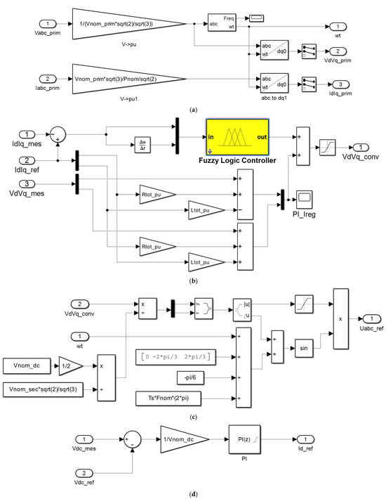
Figure 8.
Various key constituents of the proposed fuzzy-based current controller. (a) PLL and measurements. (b) Fuzzy-based current controller. (c) Reference generator. (d) DC voltage regulator.
Therefore, the measurements must be transformed using Park’s transformation, which is provided, from the frame to the frame given in Equation (11).
However, are the voltages in the dq frame corresponding to voltages in the abc frame. From the block diagrams shown in Figure 7, the following mathematical equations, Equations (12) and (13), of the inverter in terms of the electrical network can be obtained.
where are the resistance and inductance of the chock of an inverter. The error signal and change in error signal of the current controller are obtained as given in Equations (14) and (15).
The proposed fuzzy logic controller has been implemented by considering (i) seven fuzzy sets, respectively, for each input/output variable; (ii) a triangular membership function for easiness; (iii) implication using the Mamdani-type min operator; and (iv) defuzzification using the height approaches. Fuzzy logic uses linguistic variables instead of using numerical variables. The following categories can be used in a control system to identify errors between the set point and output signals: Negative Large (NL) is represented by ‘−L’; Negative Medium (NM) is represented by ‘−M’; Negative Small (NS) is represented by ‘−S’; Zero (ZE); Positive Small (PS) is represented by ‘+B’; Positive Medium (PM) is represented by ‘−M’; and Positive Large (PL) is represented by ‘+L’. Fuzzification is the process of changing a real number, or numerical variable, into a fuzzy number, or linguistic variable. The language control rules needed by the rule evaluator (decision-making logic) are stored in the rule base, and the list of rules that are applied in this work is given in Table 2.

Table 2.
Fuzzy rules developed for current-controlled voltage source inverter.
The schematic view of the developed fuzzy logic controller in the Simulink environment is shown in Figure 9. The 3D fuzzy rule surface designed for the suggested fuzzy logic-based current regulator is shown in Figure 10. It illustrates how changes in error and variations in error affect the output control signal. The surface exhibits continuous gradients and smooth transitions, demonstrating the controller’s capacity to produce nonlinear and adaptive control actions. In the PV-FC microgrid system, this adaptive behavior aids in ensuring a quick and steady dynamic response to changing power demands. Following the adjustment of the membership functions and fuzzy rules unique to the system dynamics, the rule surface was built using MATLAB’s FIS editor.

Figure 9.
Schematic view of fuzzy logic controller.
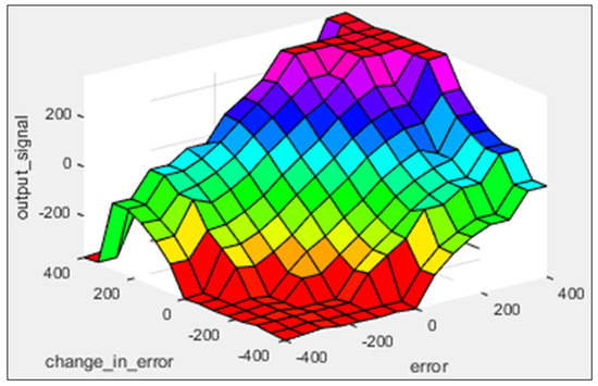
Figure 10.
Surface plot obtained for the proposed fuzzy logic controller.
4. Discussion and Analysis of Simulation Findings
To evaluate the effectiveness of the suggested fuzzy-based current controller for the PV-FC hybrid microgrid voltage source inverter, several power quality metrics are taken into account under various test scenarios. These include voltage swell and sag, deviations in frequency profile, and THD. MATLAB/Simulink 2022a (runtime version of the software is 9.1 and executed on Windows 64-bit OS) is used to model the suggested PV-FC hybrid microgrid with the proposed control technique. The overall simulation model of the proposed PV-FC hybrid microgrid plant is shown in Figure 11.
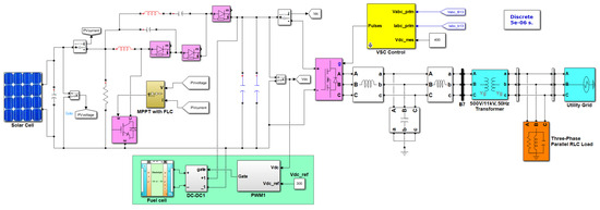
Figure 11.
Simulation model of the proposed PV-FC hybrid microgrid system.
Various power quality indices, namely, (i) voltage characteristics, (ii) frequency characteristics, (iii) power factor, (iv) power characteristics, and (v) total harmonic distortion, are computed for both conventional and proposed systems and compared. To produce these characteristics, various test scenarios and testing procedures that are described in Table 3 are implemented.

Table 3.
Power quality study: test scenarios and procedure.
4.1. Voltage Characteristics
A short decrease in voltage magnitude is known as voltage sag. These are generally caused by faults or load currents applied quickly. In a similar vein, abruptly removing the load raises the voltage magnitude and decreases the source current during voltage swells. This section discusses the performance of the hybrid microgrid under various test scenarios for the computation of voltage sag/swell at the PCC, using an ANN-based conventional control technique and the fuzzy-based proposed current controller. The PCC voltage of the microgrid is kept at 415 volts and 50 Hz. Run the system shown in Figure 11 by considering the test scenarios 1(a) and 1(b) of Table 3 for investigating the sag and swell. From the results shown in Figure 12a,b, a voltage sag of 46.15% with the conventional ANN controller and 37.5% with the proposed fuzzy controller, and a voltage swell of 10.25% with the conventional ANN controller and 7.5% with the proposed fuzzy controller, are observed.
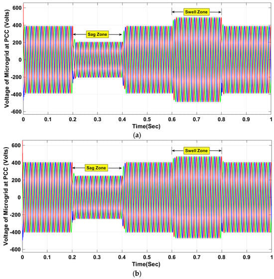
Figure 12.
Voltage sag and swell at the PCC of PV-FC hybrid microgrid (a) with ANN controller and (b) proposed fuzzy controller.
In both cases, the proposed controller showed its dominance. Measuring voltage imbalance is essential for preserving microgrid stability, equipment safety, and power quality. In microgrid operations, proactive monitoring and mitigation guarantee standard compliance, boost productivity, and avert expensive breakdowns. In this respect, test scenario 1(c) of Table 3 is considered for studying the voltage imbalances for both conventional and proposed controllers. From the results shown in Figure 13a,b, an inductive load 100 kVAR is injected at a time of 0.15 s, and it is observed that voltage imbalance is 3.11% with the conventional ANN-based controller and 1.03% with the proposed fuzzy controller. This case also proved the efficacy of the proposed fuzzy controller.
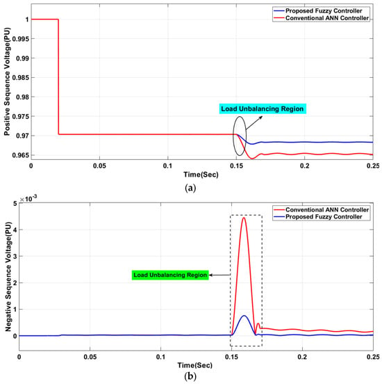
Figure 13.
Voltage imbalances at the PCC of PV-FC hybrid microgrid with ANN controller and proposed fuzzy controller for (a) positive sequence voltage and (b) negative sequence voltage.
4.2. Frequency Characteristics
When a microgrid is functioning in autonomous/grid-integrated mode, frequency is an essential property that must be continuously checked and controlled. To evaluate the efficacy of the proposed controller, test scenarios 2(a), 2(b), and 2(c) of Table 3 are considered, and the corresponding results are shown in Figure 14. In all the test cases, different loads are considered.
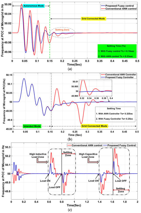
Figure 14.
Frequency characteristics at the PCC of PV-FC hybrid microgrid with conventional ANN controller and proposed fuzzy controller for (a) pure resistive loads, (b) constant impedance loads, and (c) high dynamic reactive loads.
The following is the summary of observations noted from Figure 14 that indicate the superiority of the proposed controller.
- (i).
- Figure 14a shows how frequency characteristics vary with a resistive load of 350 kW. From this, a settling time of 0.23 s is observed with the conventional ANN controller, while it is reduced to 0.16 s with the proposed fuzzy controller.
- (ii).
- Figure 14b shows how frequency characteristics vary with a constant impedance load of 275 kW + j150 kVAR. From this, a settling time of 0.32 s is observed with the conventional ANN controller, while it is reduced to 0.2 s with the proposed fuzzy controller.
- (iii).
- Figure 14c shows how frequency characteristics vary with a high dynamic reactive load in the manner described below to investigate the frequency variations.
- ▪
- Switch the inductive load ON for 0.6 s and OFF for 0.8 s.
- ▪
- Turn the capacitive load ON for 1.4 s and OFF for 1.6 s.
In this case, it is seen that the proposed fuzzy controller exhibited superior characteristics by reducing the deviation compared to the conventional ANN controller.
In all the cases discussed above, the proposed fuzzy-based controller outperformed the conventional ANN-based controller. Therefore, with a reduced settling time, the transient stability of the system under consideration is improved.
4.3. Power Factor
Power quality, system efficiency, and operational stability are all directly impacted by power factor (PF), a crucial microgrid characteristic. It gauges how efficiently electrical power is being used by calculating the ratio of real power (kW) to apparent power (kVA). In both grid-connected and islanded microgrids, low power factors can result in inefficiencies, voltage dips, and higher losses. Consider the test scenario 3 of Table 3, to evaluate the efficacy of the proposed controller. In this case, a base impedance load of 275 kW + j50 kVAR and a test load of 150 kW are applied at the PCC of the microgrid from 0 s to 0.5 s. It is observed from Figure 15 that the power factor with conventional ANN controller is 0.745 and the power factor with proposed fuzzy controller is 0.767. Clearly, the proposed controller shows its dominance in this case also.
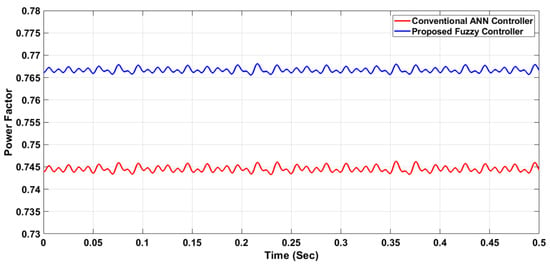
Figure 15.
Power factor at the PCC of the PV-FC hybrid microgrid with conventional ANN controller and proposed fuzzy controller.
4.4. Power Characteristics
Maintaining power quality, guaranteeing stability, and maximizing efficiency in microgrids all depend on monitoring active power (P, in kW) and reactive power (Q, in kVAR). These measurements support load balancing, real-time control, and grid standard compliance. Massive reactive loads are injected at the PCC to observe the transient fluctuations in real power and reactive power characteristics of the proposed hybrid solar PV-FC-based microgrid system as per test scenario 4 of Table 3. Between 0.1 and 0.2 s, a test load of −j150 kVAR is injected, followed by a j100 kVAR inductive load between 0.3 and 0.4 s. The active and reactive powers for the injected loads at the cluster’s PCC fluctuate, as demonstrated by the simulation results displayed in Figure 16a,b. These findings support the significance of the suggested controller for the inverters of the hybrid system application by demonstrating a lower transient deviation in the characteristics obtained with the proposed controller in comparison to the conventional controller.
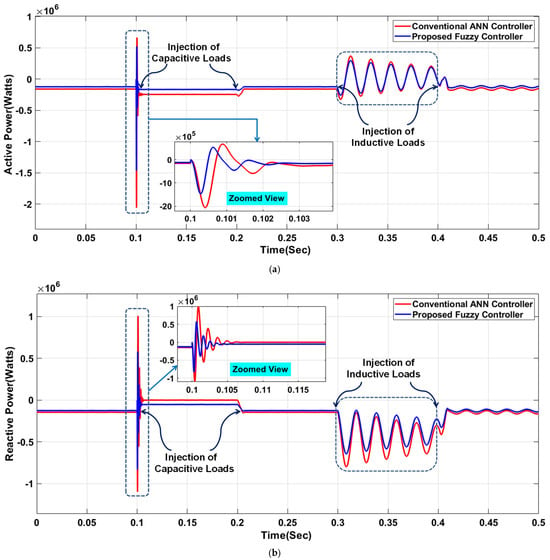
Figure 16.
Power characteristics at the PCC of the PV-FC hybrid microgrid with conventional ANN controller and proposed fuzzy controller: (a) active power and (b) reactive power.
4.5. THD Results
Non-sinusoidal waveforms of current or voltage that differ in frequency from the fundamental frequency are known as harmonics. Nonlinear voltage/current characteristics drawn by power system equipment are the general reasons for the harmonic distortion in the system. Power electronic converters and nonlinear loads are the primary causes of the dominance of current harmonics in the microgrids. Because of the system impedance, the generated current harmonics may also cause an increase in the voltage harmonics in the microgrids. Thus, to examine the effect of major impedance loads, the following loads are injected into the system. To observe the THD of the PV-FC hybrid microgrid, test scenario 5(a) of Table 3 considered a load of 650 kW load applied from 0.15 s to 0.2 s along with the base load of 450 kW + j50 kVAR. From the results depicted in Figure 17, it is realized that THD is 5.37% with the ANN controller and THD is 3.6% with the proposed fuzzy controller.
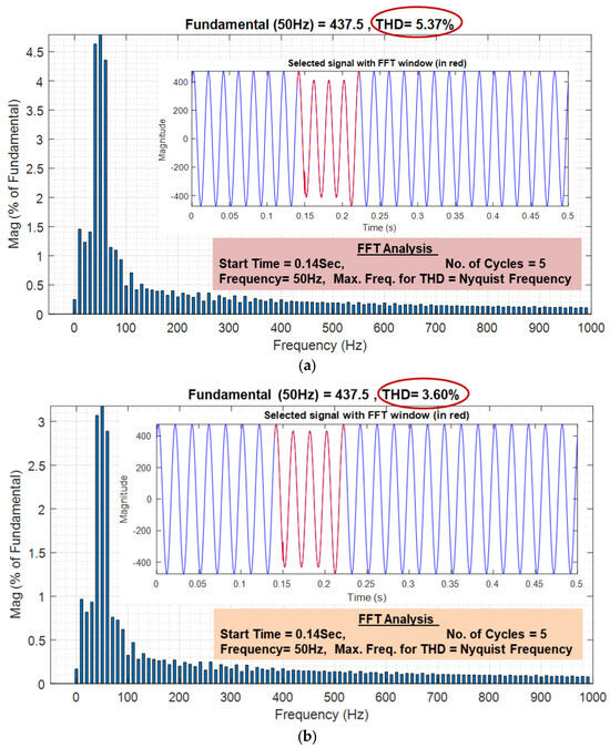
Figure 17.
THD of PV-FC hybrid microgrid, (a) with conventional ANN controller and (b) proposed fuzzy controllers with huge resistive loading.
A test scenario 5(b) of Table 3 is considered; a load of j100 kVAR and −j150 kVAR loads are applied from 0.15 s to 0.2 s along with the base load of 450 kW + j50 kVAR. From the results depicted in Figure 18, it is realized that THD is 3.26% with the ANN controller and THD is 2.44% with the proposed fuzzy controller.
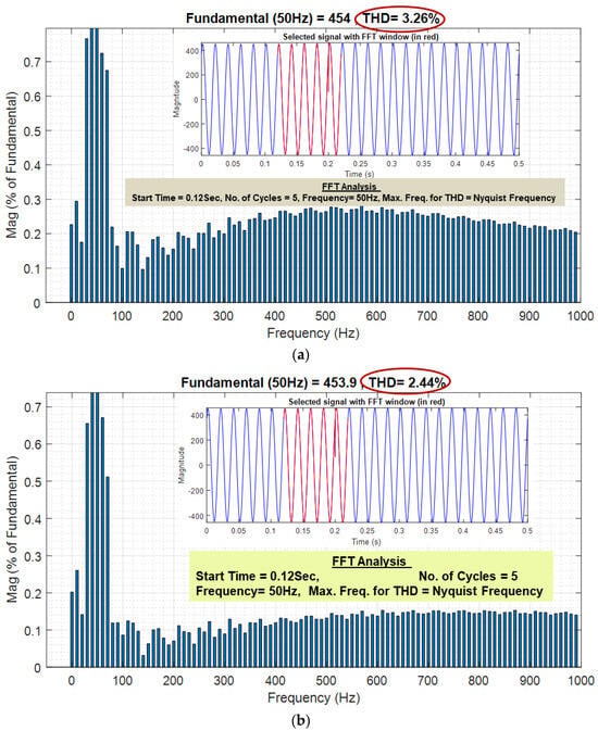
Figure 18.
THD of PV-FC hybrid microgrid, (a) with ANN controller and (b) proposed fuzzy controllers with huge reactive loading.
From this section, it is evident that, in all the cases, the hybrid microgrid with the proposed fuzzy-based current controller gives fruitful results due to lower THD values. Excessive harmonics in any power system lead to overheating of transformers and cables, overloading of the neutral in a three-phase line, and voltage deviations in the secondary distribution. Transformers in power system networks lead to a number of problems, including increased system power loss, increased heat and copper losses in the electrical devices, increased thermal stress and dielectric losses in capacitor banks, and an impact on measuring instrument performance that results in protective relay failure.
The quantitative comparison of the results obtained with conventional and proposed controllers concerning all performance characteristics is given in Table 4.

Table 4.
Quantitative comparison of key power quality parameters.
5. Conclusions
To improve the power quality of the PV-FC-based hybrid microgrids, the fuzzy-based current controller concept is presented in this study. For the suggested system, several indices are examined and quantified quantitatively, including voltage sag/swell profile, frequency profile, and THD profile. These cumulative findings provide the following summary of the key advantages of the suggested controller.
- ▪
- The suggested fuzzy controller resulted in a voltage sag of 37.5%, compared to 46.15% with the traditional ANN controller. However, voltage swell has been slightly improved, which is 10.25% with ANN and 7.5% with the suggested fuzzy controller.
- ▪
- The suggested fuzzy controller resulted in a voltage imbalance of 1.03%, compared to 3.1% with the traditional ANN controller, which violated the IEEE standard.
- ▪
- The suggested system’s settling time with conventional and proposed controllers is examined under different loads. The quantitative results show that, when compared to conventional ANN (0.23 s), the frequency characteristic of the microgrid requires much less time to settle in the steady state with the proposed fuzzy-based controller (0.16 s) with pure resistive loads. Similarly, when compared to conventional ANN (0.32 s), the frequency characteristic of the microgrid requires much less time to settle in the steady state with the proposed fuzzy-based controller (0.2 s) with constant impedance loads. The suggested controller improves steady-state stability since it has a less settling period.
- ▪
- Based on the power factor plots, it is verified that suggested controller performance gives fruitful results.
- ▪
- Based on the THD results, it can be said that the suggested controller outperformed the other controller when there were different impedance loading situations.
Thus, the suggested fuzzy-based current controller has successfully outperformed the conventional ANN-based controller, increasing the utility of the microgrid installations, according to this study’s results. Apart from the validation based on simulation, the aforementioned findings of this study apply to PV-FC hybrid microgrid systems in the actual world. The suggested fuzzy-based current-controlled voltage source inverter can be used successfully in applications that need good power quality, like grid-tied urban distributed energy systems, distant or rural microgrids, and vital infrastructure facilities like data centers or hospitals. It is advised that the suggested control system be implemented practically utilizing real-time digital controllers that allow fuzzy logic-based operations, such as DSPs or FPGAs. As the next step towards field implementation, pilot-scale experimental validation under standardized grid settings (e.g., IEEE 1547 [32] or IEC 61727 [30]) is encouraged.
5.1. Relevance of This Research to Sustainable Development Goals
The United Nations Sustainable Development Goal 7 (SDG 7) states that advancements in industry, education, health, and climate action depend on everyone having access to modern, affordable, dependable, and sustainable energy. To lessen reliance on fossil fuels and slow down climate change, two important goals (SDGs 7.1, 7.2, and 7.3) are improving energy efficiency and raising the proportion of renewable sources. By suggesting a control technique to improve power quality and reliability in microgrids based on renewable energy, the work provided in this paper directly supports these objectives. The results support clean energy technology development and sustainable energy infrastructure, which is in line with the world’s sustainability goals.
5.2. Limitations and Future Scope
Although Simulink-based studies show that the suggested fuzzy-based current-controlled voltage source inverter performs better in terms of power quality, there are a few limitations to be noted.
- ▪
- There has been no real-time hardware-in-the-loop or laboratory prototype testing performed for this study; it is fully based on MATLAB/Simulink 2022a models.
- ▪
- Expert judgment and trial-and-error were used to fine-tune fuzzy membership functions and rule bases; systematic auto-tuning or optimization methods were not used.
Thus, hardware implementation, fault-ride-through capability, adding more renewable sources (such as wind turbines), methodical controller optimization, and comparisons under a wider range of dynamic scenarios will be the main topics of future research.
Author Contributions
Conceptualization, Y.V.P.K.; Data curation, S.N.V.B.R. and D.J.P.; Formal analysis, S.N.V.B.R.; Funding acquisition, Y.V.P.K.; Investigation, D.J.P.; Methodology, Y.V.P.K.; Project administration, Y.V.P.K.; Resources, S.N.V.B.R.; Software, D.J.P. Supervision, Y.V.P.K.; Validation, S.N.V.B.R.; Visualization, D.J.P.; Writing—original draft, S.N.V.B.R. and Y.V.P.K.; Writing—review and editing, Y.V.P.K. and D.J.P. All authors have read and agreed to the published version of the manuscript.
Funding
This research receives no external funding.
Institutional Review Board Statement
Not applicable.
Informed Consent Statement
Not applicable.
Data Availability Statement
The original contributions presented in this study are included in the article. Further inquiries can be directed to the corresponding authors.
Conflicts of Interest
The authors declare no conflicts of interest.
References
- Alshehri, J.; Khalid, M. Power quality improvement in microgrids under critical disturbances using an intelligent decoupled control strategy based on battery energy storage system. IEEE Access 2019, 7, 147314–147326. [Google Scholar] [CrossRef]
- Choudhury, S.; Varghese, G.T.; Mohanty, S.; Venkata Ratnam, K.; Bajaj, M.; Blazek, V.; Prokop, L.; Misak, S. Energy management and power quality improvement of microgrid system through modified water wave optimization. Energy Rep. 2023, 9, 6020–6041. [Google Scholar] [CrossRef]
- Kumar, Y.V.P.; Rao, S.N.V.B.; Padma, K.; Reddy, C.P.; Pradeep, D.J.; Flah, A.; Kraiem, H.; Jasiński, M.; Nikolovski, S. Fuzzy Hysteresis Current Controller for Power Quality Enhancement in Renewable Energy Integrated Clusters. Sustainability 2022, 14, 4851. [Google Scholar] [CrossRef]
- Bharat Mohan, N.; Rajagopal, B.; Hari Krishna, D. Power quality enhancement of hybrid renewable energy source-based distribution system using optimised UPQC. J. Control. Decis. 2023, 12, 449–470. [Google Scholar] [CrossRef]
- Srikanth, M.; Pavan Kumar, Y.V.; Reddy, C.P.; Mallipeddi, R. Empowered Virtual Synchronous Generator Based Control Scheme for Improved Transient Response and Reduced Nuisance Tripping in Stable Microgrids. IEEE Access 2024, 12, 99968–99988. [Google Scholar] [CrossRef]
- Sun, Y.; Li, S.; Lin, B.; Fu, X.; Ramezani, M.; Jaithwa, I. Artificial Neural Network for Control and Grid Integration of Residential Solar Photovoltaic Systems. IEEE Trans. Sustain. Energy 2017, 8, 1484–1495. [Google Scholar] [CrossRef]
- Nagaraju, G.; Shankar, S. Power quality improvement of wind energy conversion system with unified power quality controller: A hybrid control model. Trans. Inst. Meas. Control. 2020, 42, 1997–2010. [Google Scholar] [CrossRef]
- Rajakumar, V.; Anbukumar, K.; Selwynraj, A.I. Sliding mode controller-based voltage source inverter for power quality improvement in microgrid. IET Renew. Power Gener. 2020, 14, 1860–1872. [Google Scholar] [CrossRef]
- Gupta, S.; Verma, A.; Singh, B.; Garg, R.; Singh, A. Power quality improvement of PV-WPGS based grid interactive microgrid using MSWL-CLMS control. IET Energy Syst. Integr. 2020, 2, 362–372. [Google Scholar] [CrossRef]
- Khosravi, N.; Echalih, S.; Baghbanzadeh, R.; Hekss, Z.; Hassani, R. Enhancement of power quality issues for a hybrid AC/DC microgrid based on optimization methods. IET Ren. Power Gen. 2022, 16, 1773–1791. [Google Scholar] [CrossRef]
- Khosravi, N.; Abdolvand, A.; Oubelaid, A. Improvement of power quality parameters using modulated-unified power quality conditioner and switched-inductor boost converter by the optimization techniques for a hybrid AC/DC microgrid. Sci. Rep. 2022, 12, 21675. [Google Scholar] [CrossRef] [PubMed]
- Al Sumarmad, K.A.; Sulaiman, N.; Wahab, N.I.A.; Hizam, H. Energy Management and Voltage Control in Microgrids Using Artificial Neural Networks, PID and Fuzzy Logic Controllers. Energies 2022, 15, 303. [Google Scholar] [CrossRef]
- Nair, D.R.; Nair, M.G.; Thakur, T. A Smart Microgrid System with Artificial Intelligence for Power-Sharing and Power Quality Improvement. Energies 2022, 15, 5409. [Google Scholar] [CrossRef]
- Dhanamjayulu, C.; Albert Alexander, S.; Harish, R.; Srinivasan, M.; Sarathkumar, D. Power Quality Improvement in a Solar PV Assisted Microgrid Using Upgraded ANN-Based Controller. Math. Probl. Eng. 2022, 2022, 2441534. [Google Scholar] [CrossRef]
- Das, S.R.; Mishra, A.K.; Ray, P.K.; Salkuti, S.R.; Kim, S.-C. Application of Artificial Intelligent Techniques for Power Quality Improvement in Hybrid Microgrid System. Electronics 2022, 11, 3826. [Google Scholar] [CrossRef]
- Kumar, A.; Choudhary, J. Power quality improvement of hybrid renewable energy systems-based microgrid for statcom: Hybrid-deep-learning model and mexican axoltl dingo optimizer (MADO). Eng. Res. Express 2023, 5, 045031. [Google Scholar] [CrossRef]
- Talaat, M.; Elkholy, M.H.; Alblawi, A. Artificial intelligence applications for microgrids integration and management of hybrid renewable energy sources. Artif. Intell. Rev. 2023, 56, 10557–10611. [Google Scholar] [CrossRef]
- Ravi, T.; Kumar, K.S.; Dhanamjayulu, C.; Khan, B.; Rajalakshmi, K. Analysis and mitigation of PQ disturbances in grid connected system using fuzzy logic based IUPQC. Sci. Rep. 2023, 13, 22425. [Google Scholar] [CrossRef]
- Shikha, G.; Anjeet, V.; Singh, B.; Rachana, G.; Alka, S. AES-FLL control of RES powered MG for power quality improvement with synchronization control. Electr. Power Syst. Res. 2022, 203, 107681. [Google Scholar] [CrossRef]
- Mahendravarman, I.; Elankurisil, S.A.; Venkateshkumar, M.; Ragavendiran, A.; Chin, N. Artificial intelligent controller-based power quality improvement for microgrid integration of photovoltaic system using new cascade multilevel inverter. Soft Comput. 2020, 24, 18909–18926. [Google Scholar] [CrossRef]
- Vidhya, K.; Krishnamoorthi, K. A hybrid technique for optimal power quality enhancement in grid-connected photovoltaic interleaved inverter. Energy Environ. 2022, 35, 0958305X2211405. [Google Scholar] [CrossRef]
- Dhara, A.; Choudhury, A.B.; Sarkar, D.; Pramanik, S.P. Power quality enhancement of microgrid using fuzzy logic-controlled inverter and SFCL. Microsyst. Technol. 2024, 30, 687–710. [Google Scholar] [CrossRef]
- Pei, X.; Zhao, X.; Jia, H.; Wang, H.; Liu, J. Fuzzy sliding mode control with adaptive exponential reaching law for inverters in the photovoltaic microgrid. Front. Energy Res. 2024, 12, 1416863. [Google Scholar] [CrossRef]
- Bouziane, M.; Zarour, L.; Benbouhenni, H.; Elbarbary, Z.M.S.; Colak, I.; Alammar, M.M. Genetic algorithm type 2 fuzzy logic controller of microgrid system with a fractional-order technique. Sci. Rep. 2025, 15, 6318. [Google Scholar] [CrossRef]
- Rao, S.N.V.B.; Padma, K. ANN based Day-Ahead Load Demand Forecasting for Energy Transactions at Urban Community Level with Interoperable Green Microgrid Cluster. Int. J. Renew. Energy Res. 2021, 11, 147–157. [Google Scholar] [CrossRef]
- Narendiran, S.; Sahoo, S.K.; Das, R.; Sahoo, A.K. Fuzzy logic controller based maximum power point tracking for PV system. In Proceedings of the 3rd International Conference on Electrical Energy Systems (ICEES), Chennai, India, 17–19 March 2016; pp. 29–34. [Google Scholar] [CrossRef]
- Bramareswara Rao, S.N.V.; Pavan Kumar, Y.V.; Amir, M.d.; Ahmad, F. An Adaptive Neuro-Fuzzy Control Strategy for Improved Power Quality in Multi-microgrid Clusters. IEEE Access 2022, 10, 128007–128021. [Google Scholar] [CrossRef]
- IEC 61000-4-11:2020; Electromagnetic Compatibility (EMC)—Part 4–34: Electromagnetic Compatibility (EMC)—Part 4-11: Testing and Measurement Techniques-Voltage Dips, Short Interruptions and Voltage Variations Immunity Tests for Equipment with Input Current Up to 16 A Per Phase. IEC: Geneva, Switzerland, 2020.
- IEEE Std 1159.3-2019 (Revision of IEEE Std 1159.3-2003); IEEE Recommended Practice for Power Quality Data Interchange Format (PQDIF). IEEE: New York, NY, USA, 2019; pp. 1–185.
- IEC 61727:2004; Standard—Photovoltaic (P.V.) Systems—Characteristics of the Utility Interface. IEC: Geneva, Switzerland, 2004. Available online: https://webstore.iec.ch/publication/5736 (accessed on 13 April 2025).
- IEC 61000-2-2:2002; Electromagnetic Compatibility (EMC)—Part 2-2: Environment-Compatibility Levels for Low-Frequency Conducted Disturbances and Signaling in Public Low-Voltage Power Supply Systems. IEC: Geneva, Switzerland, 2002. Available online: https://webstore.iec.ch/publication/4133 (accessed on 13 April 2025).
- IEEE Std. 1547.1-2020; IEEE Standard Conformance Test Procedures for Equipment Interconnecting Distributed Energy Resources with Electric Power Systems and Associated Interfaces. IEEE: New York, NY, USA, 2020; pp. 1–282. [CrossRef]
Disclaimer/Publisher’s Note: The statements, opinions and data contained in all publications are solely those of the individual author(s) and contributor(s) and not of MDPI and/or the editor(s). MDPI and/or the editor(s) disclaim responsibility for any injury to people or property resulting from any ideas, methods, instructions or products referred to in the content. |
© 2025 by the authors. Licensee MDPI, Basel, Switzerland. This article is an open access article distributed under the terms and conditions of the Creative Commons Attribution (CC BY) license (https://creativecommons.org/licenses/by/4.0/).