Article

Real-Time 3D Reconstruction for the Conservation of the Great Wall’s Cultural Heritage Using Depth Cameras

1
School of Architecture and Design, Beijing Jiaotong University, Beijing 100044, China
2
School of Vehicle and Mobility, Tsinghua University, Beijing 100084, China
*
Author to whom correspondence should be addressed.
Sustainability 2024, 16(16), 7024; https://doi.org/10.3390/su16167024
Submission received: 12 June 2024 / Revised: 1 August 2024 / Accepted: 13 August 2024 / Published: 16 August 2024
(This article belongs to the Special Issue Heritage Preservation and Tourism Development)

Abstract

:
The Great Wall, a pivotal part of Chinese cultural heritage listed on the World Heritage List since 1987, confronts challenges stemming from both natural deterioration and anthropogenic damage. Traditional conservation strategies are impeded by the Wall’s vast geographical spread, substantial costs, and the inefficiencies associated with conventional surveying techniques such as manual surveying, laser scanning, and low-altitude aerial photography. These methods often struggle to capture the Wall’s intricate details, resulting in limitations in field operations and practical applications. In this paper, we propose a novel framework utilizing depth cameras for the efficient real-time 3D reconstruction of the Great Wall. To overcome the challenge of the high complexity of reconstruction, we generate multi-level geometric features from raw depth images for hierarchical computation guidance. On one hand, the local set of sparse features serve as basic cues for multi-view-based reconstruction. On the other hand, the global set of dense features are employed for optimization guidance during reconstruction. The proposed framework facilitates the real-time, precise 3D reconstruction of the Great Wall in the wild, thereby significantly enhancing the capabilities of traditional surveying methods for the Great Wall. This framework offers a novel and efficient digital approach for the conservation and restoration of the Great Wall’s cultural heritage.

1. Introduction

The Ming Great Wall is a robust and expansive military defense system characterized by its integrity, systematization, and hierarchical structure, all of which are governed by a military management system. The Ming Great Wall, a typical representative of the Great Wall of China, has endured substantial damage and degradation. Survey findings indicate that the remnants of this structure have been severely compromised by natural elements, including earthquakes, floods, and wind-induced erosion, as well as by human-induced activities such as road construction, mining, urbanization, and tourism development. The conservation of the Great Wall faces several challenges in practice, notably the limited regulatory enforcement, overlapping administrative roles, a lack of dedicated conservation personnel, and unregulated development, which are critical issues in ongoing preservation efforts. An unscientific conservation mechanism and unreasonable initiatives are important reasons for the large-scale destruction and decay of the military defense system of the Great Wall. Meanwhile, the lack of scientific and effective restoration techniques and standards for the Great Wall has inevitably caused the “restorative destruction” of the Great Wall in some areas. Therefore, it is urgent to formulate corresponding conservation methods and measures based on holistic study to protect the cultural heritage of the Great Wall scientifically. Traditional measurement techniques have the characteristics of high requirements for operation skills and experience, high maintenance costs, and great influence by complex environmental factors and geometric structures [1].
In this paper, we propose a novel framework utilizing depth cameras for the efficient real-time 3D reconstruction of the Great Wall, which has the advantages of low operation difficulty, low requirements for environmental conditions, high collection efficiency, high collection accuracy, etc. To overcome the challenge of high complexity of reconstruction, we generate multi-level geometric features from raw depth images to provide hierarchical computation guidance. On one hand, the local set of sparse features serve as basic cues for multi-view-based reconstruction. On the other hand, the global set of dense features is employed for optimization guidance during reconstruction. The proposed framework facilitates the real-time, precise 3D reconstruction of the Great Wall in the wild, thereby significantly enhancing the capabilities of traditional surveying methods for the Great Wall. This framework provides a novel and efficient digital approach for the conservation and restoration of the Great Wall’s cultural heritage.
Moreover, the 3D models can be visualized in real-time during the reconstruction process, which is convenient for users to carry out real-time monitoring and adjustments and provide timely feedback on the quality and accuracy of the collected data. In addition, it can also be supplemented by the UAV low-altitude photogrammetry technology in practice. This study captures the depth images of the wall facade of the Great Wall in the Juyongguan area and generates point cloud models. The projection and correspondence results between the 2D and 3D data are constructed for architectural damage records and dynamic monitoring. The internal structure of the building is further interpreted in the 3D model built based on point cloud data. According to the high-precision scanning data, architectural details and optical features can be recorded and browsed intuitively, providing essential and fundamental information for the digital conservation and utilization of traditional buildings.
The codes of this paper are provided at https://github.com/wallrecon/walldepth_pc (accessed on 1 August 2024).

2. Literature Review

2.1. Main Technologies for Architectural Heritage Data Collection

Existing 3D data acquisition techniques for architectural heritage include non-prism total station acquisition [2], ground close-up multi-view photography [3], and drone tilt photography [4].
The basic principle of non-prism total station measurement is to determine the position of the measurement point through the reflected back laser beam [5]. However, this method is greatly affected by the nature of the object and environmental factors, which can lead to measurement errors [6]. In the measurement of the building facade, Zeng Panli et al. proposed a building facade measurement method combining 3D laser scanning and total station, which can complete the operation efficiently and quickly, breaking through the limitations of traditional total station measurement [7].
Based on photogrammetry, ground close-up multi-view photography technology uses passive optical sensors to obtain a series of consecutive photographs with a certain overlap rate, and indirectly obtains 3D data through the corresponding algorithms [8]. However, this method has difficulty in acquiring multi-angle building data and raises high requirements for environmental conditions such as light and weather [9]. Sun Zheng et al. combined traditional photogrammetry techniques and automatic algorithms in the field of computer vision to create an image-based 3D reconstruction method. This technique can extend the fine mapping of architectural heritage to a wider geographical area and collect more abundant information [10].
UAV tilt photography technology consists of a vehicle, a camera, and other related equipment, which collects information from a tilted angle to make the acquired feature information more complete [11]. However, UAV tilted photography is prone to cause blind spots, resulting in incomplete information collection and affecting the quality of modeling [12]. Moreover, UAVs cannot fly over some sensitive areas due to relevant laws and policies. In this regard, He Yuanrong et al. proposed a 3D reconstruction method that combines 3D laser scanning and tilt shadow measurement techniques, and they used a feature point matching algorithm to achieve the accurate fusion of multi-source data, thus constructing a complete 3D model of indoor and outdoor buildings [13].
The three techniques have different advantages and limitations, which are mainly manifested in four aspects [14]: the data acquisition cost, mapping space location, mapping environment requirements, and data error resolution. The differences are listed in Table 1 below.

2.2. Challenges in the Collection of Architectural Heritage Information

China has been a latecomer in the application of architectural digitization, and the study of 3D digital acquisition and the application of architectural heritage in both China and foreign countries has been in an unfocused direction [15]. On the one hand, the research resources are insufficient due to rapid technological changes and the high cost of equipment. On the other hand, the application of the results of the technology is separate from the preliminary data acquisition work, which makes the results impractical. In addition, the limitations and shortcomings of traditional 3D spatial data acquisition methods in terms of the measurement accuracy, reliability, equipment cost, data processing, and application scenarios limit the development and application of 3D spatial measurement technology. Additionally, due to the portability of RGB-D cameras in capturing depth data, some methods have employed RGB-D cameras for the 3D reconstruction of simpler structures, such as monuments [16,17].
The existing information acquisition methods necessitate unified offline modeling after large-scale information collection. Due to the immense scale and vast distribution of the Great Wall, repeated information acquisition during the conservation process is challenging, and offline modeling significantly reduces the efficiency of data processing. In the meantime, existing low-altitude information acquisition methods are deeply affected by the control of various places. Due to the long acquisition distance, it is difficult to capture some local details, and the efficiency of indoor and outdoor co-construction is low. Additionally, due to the large scale and complex structure of the Great Wall, existing traditional methods based on RGB-D cameras encounter issues with registration failure and geometric inconsistency.
In view of the above limitations, in order to better achieve the goal of digital architectural heritage preservation, this study optimized the 3D spatial data acquisition method, which improves the real-time modeling efficiency of data acquisition while enhancing the information acquisition accuracy and provides better effects of heritage information display and utilization.

3. Methodology

3.1. Overall Framework

The framework of the proposed depth camera-based architectural heritage 3D reconstruction method, as illustrated in Figure 1, is composed of four modules: (1) adjusting and fixing the angle of the depth camera; (2) selecting the area to acquire information; (3) planning the area acquisition route; and (4) acquiring the target ground and building facade along the set route and obtaining the site point cloud model. We provide a process description for the four modules within the framework in Section 3.2, followed by an explanation of the specific mathematical derivation process for the fourth module in Section 3.3.

3.2. Process of Modules

3.2.1. Adjust and Fix the Angle of the Depth Camera

The height of the ancient building to be scanned was measured or estimated for the first step. Specifically, all parts of the building from the ground to the roof were measured, including the walls, windows, doors, eaves, roofs, etc. According to the maximum field of view of the depth camera and the height of the measurer, the angle between the camera and the bracket was adjusted to satisfy the vertical maximum viewing angle of the camera to cover the target building so that the height of the facade was greater than that of the building. In addition, for buildings with a height of more than 8 m, it is necessary to use multiple scanning and stitching to obtain the complete facade data. The consideration of the building height and shape is imperative to ascertain the optimal scanning position and angle for acquiring the most precise data.

3.2.2. Select Traditional Building Areas to Be Examined

Depending on the size and shape of the building scenes to be scanned, the floor area formula can be used to calculate the area covered. Most buildings to be scanned are rectangular, and a formula (area = length × width) can be used to calculate the area. Before the scanning process, the whole area of the building is divided into several small areas so that each area can be scanned separately. In addition to the building, the surrounding environment and terrain need to be considered to ensure the integrity and accuracy of the scanning results. Generally speaking, the scanning area can be divided according to different parts of the building and structural characteristics, such as the front, back, interior, and exterior.

3.2.3. Plan Regional Collection Routes

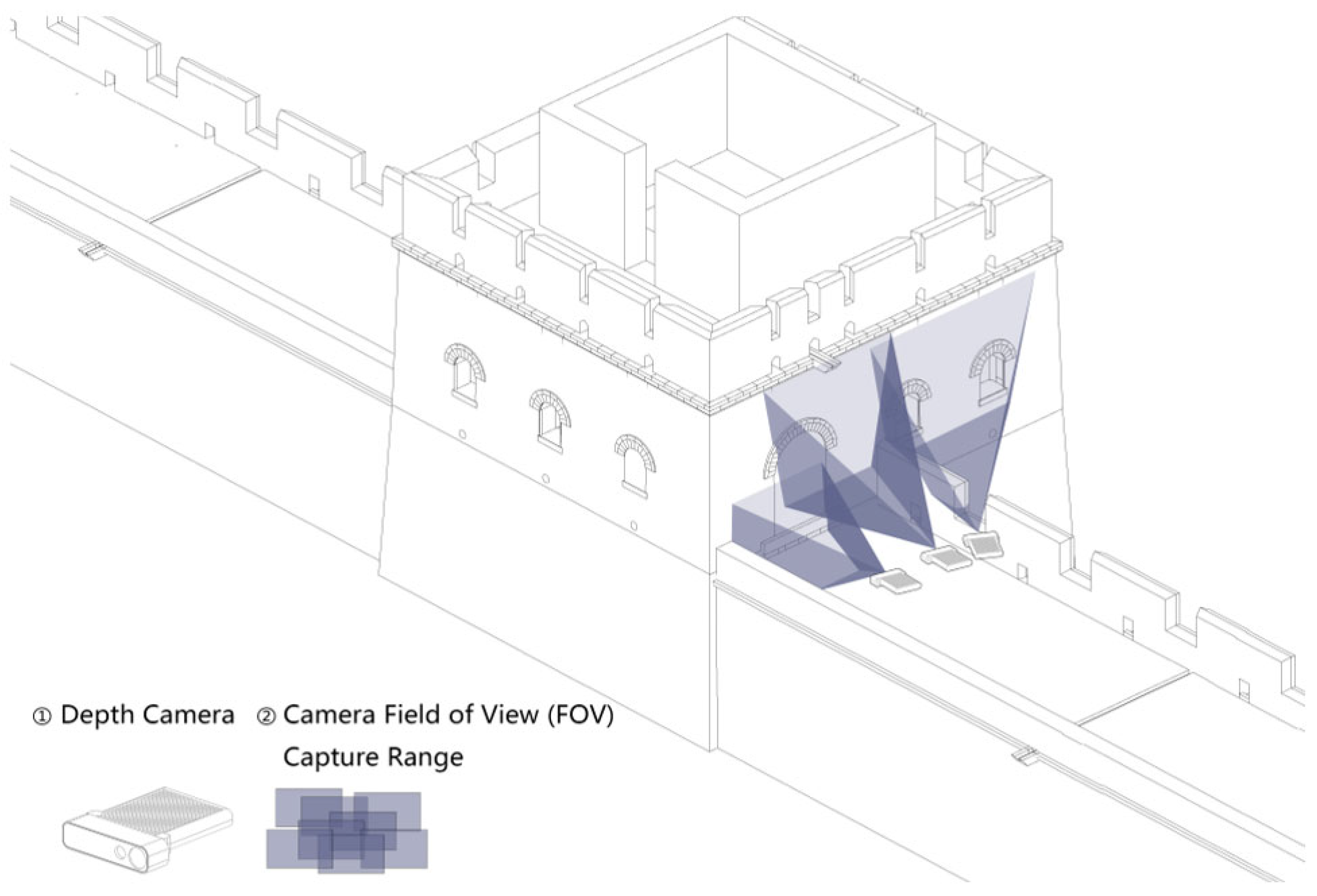
Planning architectural heritage area collection routes is the next step. First, the boundaries of traditional buildings are defined in order to determine the areas to be covered by the scanning equipment. The main structure and elements of buildings need to be identified so that the equipment can capture the details and features of the building in their entirety. As shown in Figure 2, the scanning route should cover as much area as possible while considering the scanning range and mobility of the equipment. The defined scanning route is converted into a route scheme, that is, the scanning order and scanning direction for each small area are determined. The scanning process is completed according to the route scheme to ensure that the equipment can scan each small area completely without route crossing to minimize overlapping and missing point clouds.

3.2.4. Collecting Target Ground and Building Facades along Set Routes and Obtaining Site Point Cloud Models

Once the preparatory work is completed, continuous acquisition along the set route is implemented, including the target ground and building facade. Depth image data are collected along the planned route, and the data cover the depth image, acceleration data, and timestamps. The system can automatically compute the time-sequence packet and obtain a dense point cloud and 3D model. As needed, the front and back clutters in the house door data can be automatically removed in 3D editing software (Cloudcompare 2.14) and then projected into an orthophoto image that is not disturbed by external objects [18]. The introduction of a 3D reconstruction technique based on a depth camera can obtain complete elevation maps of historical buildings with distortion-free images and high acquisition efficiency.
The proposed framework and device offer a significant enhancement in the efficiency and precision of measurement acquisition when contrasted with conventional 3D scanning methodologies, leveraging the benefits of handheld devices to conserve labor and time. Compared to the traditional total station surveying and ground close-up multi-view photography methods, the integrated wearable handheld device is lighter than both and easy to move around during field work.
The proposed device can realize real-time and automatic image processing and can also avoid tediousness during manual data processing. Real-time information acquisition helps achieve rapid response and decision making, and the blind areas can be observed and supplemented in time during the data acquisition of some structurally complex buildings.
The complexity and variety of 3D model file formats at this stage makes the access, use, and study of the file formats more difficult. Different processing platforms are needed for file loading and format conversion so that the 3D data can finally be stitched into a unified coordinate system. The data collected by the equipment can generate 3D models in a common output format, and the data can be processed and stored in an open-source software such as CloudCompare 2.14 or MeshLab 2022.02.
Furthermore, we provide detailed derivation of the point cloud models’ reconstruction in Section 3.3.

3.3. Derivation of Point Cloud Model Reconstruction

This paper proposes a framework for real-time simultaneous localization, information acquisition, modeling, and coloring utilizing a depth camera. The development of RGB-D technology began in the late 2000s, with rapid popularization following the release of Microsoft Kinect. Kinect utilized infrared and RGB cameras to achieve low-cost depth sensing, which propelled advancements in computer vision and robotics. Subsequently, RGB-D technology found widespread applications in areas such as indoor navigation, gesture recognition, and 3D reconstruction, further driving the rapid development of hardware and algorithms. In recent years, the advent of deep learning has further enhanced the processing and application of RGB-D data, fostering greater sophistication and intelligence. Due to the portability of RGB-D cameras in capturing depth data, they have been employed in the 3D reconstruction of simpler structures, such as monuments [16,17]. However, the vast scale and intricate structure of the Great Wall pose significant challenges for traditional RGB-D camera-based methods, leading to issues with registration failure and geometric inconsistency. In this study, we develop a portable handheld real-time 3D acquisition device by integrating a depth camera, a laptop, and custom-designed support structures tailored to the intricate architecture of the Great Wall.
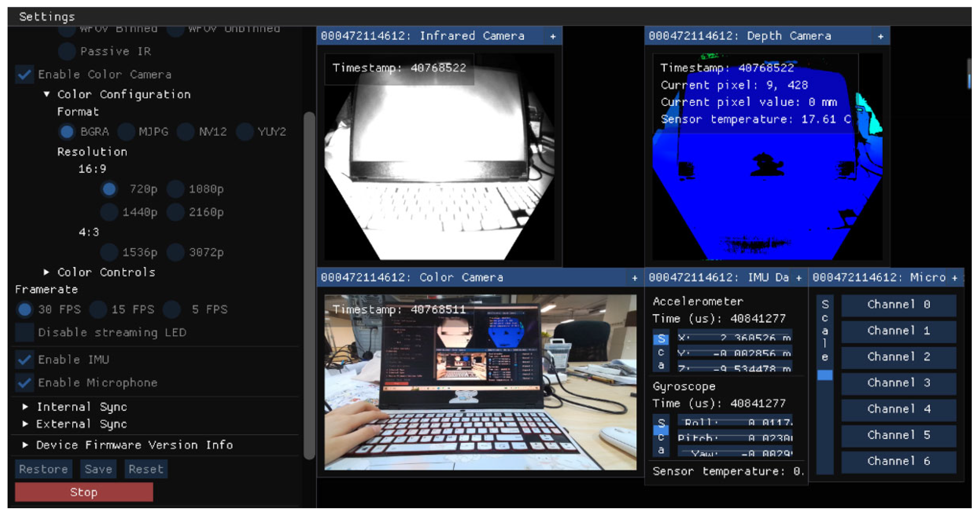
As illustrated in Figure 3, the depth camera captures depth maps, IR grayscale images, and RGB images, which are subsequently used to generate a 3D colored point cloud model through registration and projection utilizing IR-modulated light.
Given series of RGB images, depth maps, and IR images captured from the depth camera, this method extracts optical information (basic red, green, and blue values) from RGB images with depth information from depth maps to rebuild the 3D models of the scenes. The key algorithm of the method aims to build a registration model to match the RGB value and depth value of the same point or object together, where the RGB values are captured from the RGB sensors and the depth values are captured from the TOF sensors, respectively.
The overall framework of our method is composed of three stages, including Feature Extraction and Matching, Pose Estimation, and Optimization and Mapping. Specifically, each stage is carried out as follows:
  • Feature Extraction and Matching: To obtain the modality-invariant features from the RGB images and depth maps based on the protection and repair requirements of ancient buildings, SIFT (Scale-Invariant Feature Transform) is adopted for geometric feature extraction [19]. Given a set of RGB images I n n = 1 K and depth maps D n n = 1 K , where I n and D n denote the i -th RGB image and depth map, and K is the number of image frames, the RGB features f m I m = 1 L and depth features f m D m = 1 L are extracted using the SIFT algorithm. L denotes the number of feature points in this set and L = x K , where x denotes the number of feature points in each image. After obtaining the feature points of the RGB and depth images, we calculate the nearest point for each feature point to achieve cross-modal feature registration. For better representation, the feature registration can be defined as follows, minimizing the expected distance:
    D * = i = 1 , i j M f i I f j D 2
    where 2 denotes the L2 norm function for distance metric evaluation, and f i D represents the matched depth feature point of the RGB feature point f i I .
  • Pose Estimation: After obtaining the corresponding relationship from feature matching, the PnP algorithm is adopted for the pose estimation of image frames [20]. The objective is to estimate the camera pose R , t of each image frame. Specifically, the estimated poses are calculated by minimizing the re-projection error given the depth points (3D points) and their corresponding RGB pixels (2D points):
    min R , t i = 1 M p i R P j + t 2
    where p i is the RGB pixels of the feature points f i I , P j is the depth point of f j D , and f j D is the nearest point of f i I ranked by feature matching.
    For each RGB pixel p i , the corresponding 3D point P i can be calculated as P i = R 1 Π 1 p i t .
  • Optimization and Mapping: To refine the estimated poses and rebuild the spatial geometric structure of the target scenes, the optimization and mapping module are adopted here. The optimization and mapping of poses are achieved using the Bundle Adjustment algorithm to refine the series of poses [21]. This approach minimized the projection errors between the re-projected pixels and 3D points. For the mapping stage, the TSDF integration algorithm is used here for 3D reconstruction [22]. The TSDF value at the 3D point P i is updated as follows:
    T S D F P i = S D F P i × w o l d P i + S D F n e w P i × w n e w w o l d P i + w n e w
    where S D F P i denotes the signed distance function which represents the distance from point P i to the nearest surface point P j , and w o l d P i and w n e w denote the old and new weighted values for reconstruction, respectively. And S D F n e w P i is the new measurement of the signed distance at point P i .
Following the three aforementioned stages, our method was used to reconstruct the 3D model from the series of images.
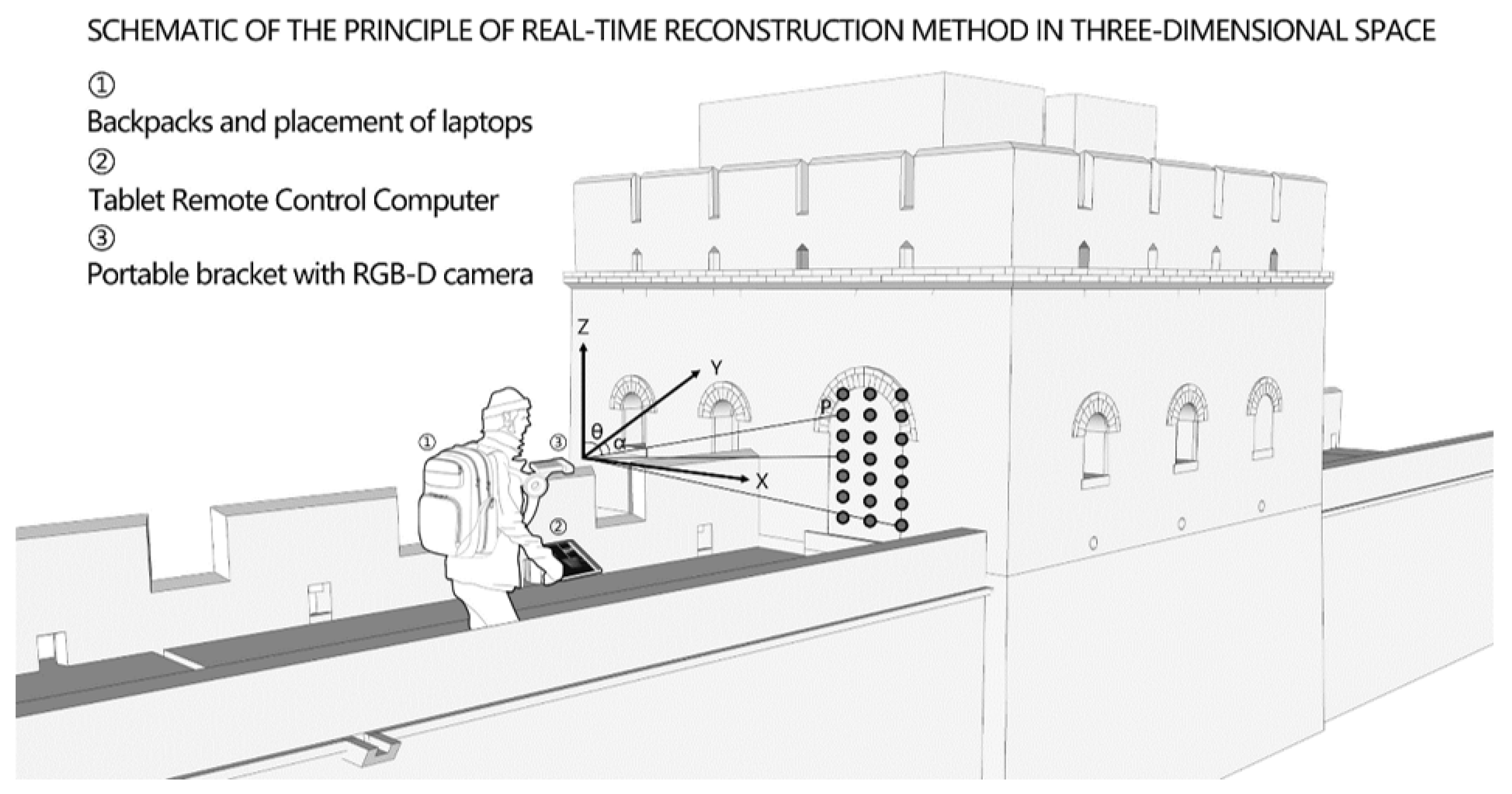
As for integration and applications, the proposed framework was implemented in an Ubuntu-based laptop connected to a depth camera, and a support structure was designed and utilized for securing two devices to facilitate their portability. As shown in Figure 4, the laptop was placed in the package and carried out terminal code running, point cloud model generation, and data storage. The tablet completes the wireless remote control of the laptop; the support structure realizes the integration of the depth camera and the tablet, and ultimately realizes the handheld three-dimensional acquisition equipment.
This study used the Azure Kinect DK depth camera to reconstruct point cloud data through the Amplitude Modulated Continuous Wave (AMCW) ToF principle. The camera projects modulated light from the near-infrared (NIR) spectrum into the scene while recording the indirect time measurements required for light to propagate from the camera to the object and from the object back to the camera. These sensors and the embedded algorithm can generate depth maps and clear IR images [23]. Additionally, the Kinect DK camera aligns depth images and RGB images and then generates a 3D colored point cloud by acquiring the internal and external parameters of the depth camera, filling in the voids in the depth map and smoothing out the noise.

4. Experiments and Analysis

4.1. Experimental Settings

4.1.1. Area for Data Collection

In this study, we scan the Juyongguan Great Wall in the Ming Dynasty as the target for the experiment, which is located in Juyongguan Village, Nankou Town, Changping District, about 46 km northwest of Beijing. Junduxian is the boundary between the West Mountain of the Taihang Mountains and the Jundu Mountain of the Yanshan Mountains, with an altitude of more than 1000 m. The steep mountain is an obstacle in the north and south. Due to the dangerous terrain of the Juyongguan Great Wall, data collection and mapping of the remains are more inconvenient. Affected by the policies and regulations in Beijing, drone aerial photography technology cannot be used to conduct low-altitude scanning, which brings more difficulty in collecting architectural heritage information. The proposed framework and device in this paper are used to investigate the local section of the Juyongguan Great Wall. The No. 13 enemy platform and the surrounding wall were selected as an example, and the device was about 2 m away from the building to ensure the integrity of the scanning results during data acquisition.

4.1.2. Data Preprocessing for the Proposed Method

Photogrammetric office work includes point cloud preprocessing and multi-view point cloud data registration. Point cloud preprocessing is the premise and foundation step of 3D point cloud registration, point cloud stitching, and 3D reconstruction, including the removal of outliers and sampling and smoothing operations [24]. The denoising and filtering of point clouds remove noisy points outside of the scanned target, including pedestrians and clutter in the surrounding environment; the purpose of point cloud segmentation is to realize region division so as to facilitate the separate processing of data.
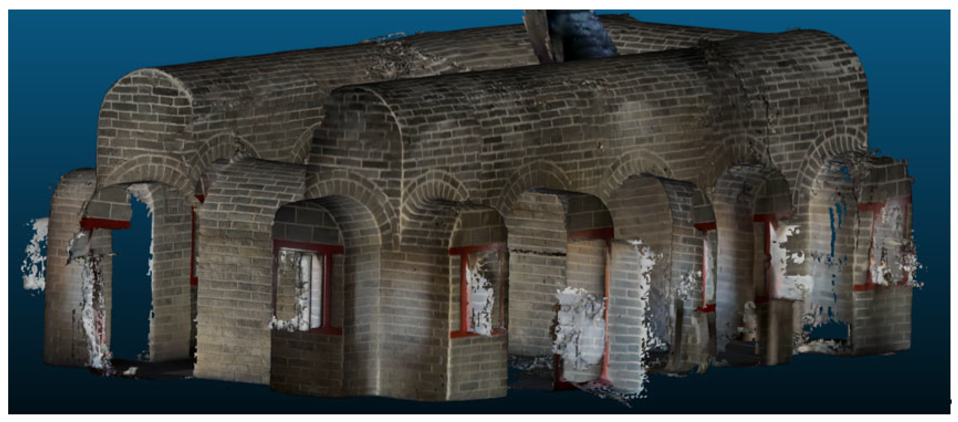
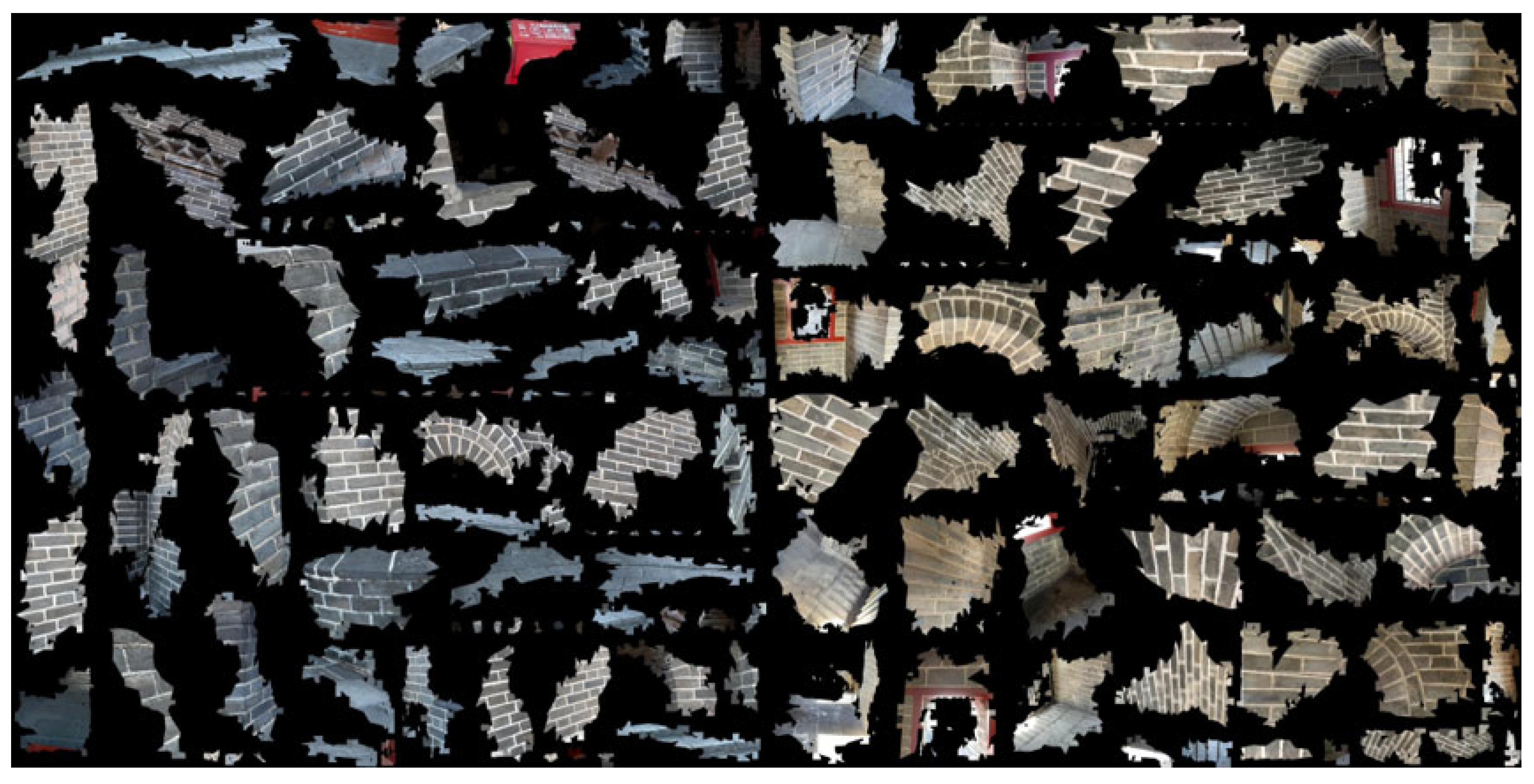
Point cloud data registration refers to the combination and stitching of point cloud data from different locations and angles to obtain complete point cloud data of a building. In order to obtain a point cloud model of a large building, it is often necessary to collect multiple distances and finally transform the data into a whole point cloud with an absolute coordinate system through registration [25]. In this study, the Meshlab software was used to realize point cloud stitching based on the target points, and a filtering tool was used to filter the noise of the point cloud (Figure 5 and Figure 6). The point cloud model after data registration is basically consistent with the shape of the actual building without obvious offset or missed layers.

4.2. Experimental Results and Analysis

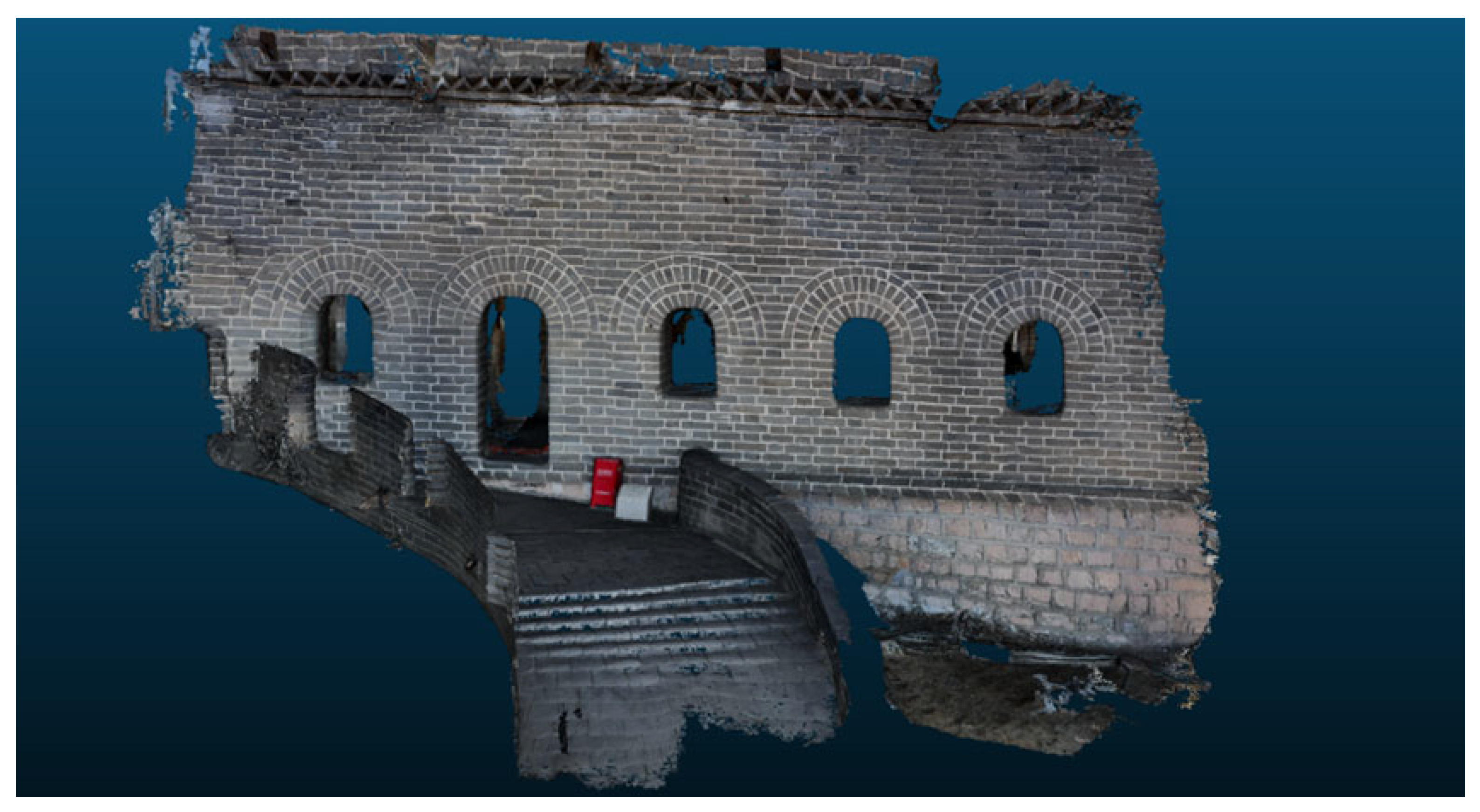
First of all, the collected point cloud data were input into the modeling software SketchUp to complete 3D model reconstruction through the Undet plug-in [26]. The starting surface of the model was determined, and the plug-in “point cloud fitting” tool was used. A relatively flat wall was selected as the starting plane, the fitting radius was set, and the software automatically fit the optimal plane. On the basis of the plane, the push and pull of some appendages and expansion modeling were implemented according to the point cloud. Finally, other tools of the plug-in can also be used to dissect, analyze, and extract the point cloud. When modeling complex components, it is necessary to extract contour lines and feature points by judging multiple angles against the point cloud and to establish components for subsequent use after component modeling. According to the established 3D model, five angles of view projection were selected in “Camera Options” of the SketchUp menu bar. The DWG format decade image was exported, and any position section was generated (Figure 7 and Figure 8).
Table 2 presents the data acquisition range, acquisition time, reconstruction time, and reconstruction speed of the collected data packages. The statistical results demonstrate the efficacy of this method, achieving an average reconstruction speed of 3.25 s per meter and thereby affirming its real-time performance.

4.3. Outlook and Comparison

4.3.1. Safety Information Monitoring of Building Heritage

Through the regular scanning of buildings, point cloud data with different time stamps can be generated to model the trend in cultural relics lesions by comparing the data from multiple scanning periods [27], including analyzing the flatness of the wall and floor, deformation of buildings, cracks in walls, or deformation of the supporting structure. Compared with other monitoring methods, point cloud data can visualize the defects and damage information of buildings and detect subtle changes such as downward sloping, twisting, and the deformation of structural components. Potential safety issues in buildings can be predicted by comparing point cloud models with different time stamps.

4.3.2. Assisted Architectural Heritage Repair and Rehabilitation

In the field of architectural heritage restoration, accurate measurement data and detailed image information are needed to better understand the state and history of ancient buildings. Point cloud data can be used for the digital reconstruction and preservation of ancient buildings. Compared with traditional mapping collection technology, the information of ancient buildings can be preserved in a more detailed and meticulous way, and the results of data visualization are more vivid [22]. Different from traditional 3D model data, point cloud data can visualize the overall spatial scale of the building and correct the errors caused by disease and damage.
Based on the output vector data of the Great Wall, the geometry information and texture information were analyzed, and the parts that need to be repaired and restored were determined to complete the operations of adding, expanding, modifying, and deleting in the 3D model. The digital model can be used to reconstruct the damaged parts of the Great Wall and measure and position the parts that need to be repaired. It is necessary to ensure the safety and sustainability of the repair and restoration process. For example, the original structure and materials of the building are protected to avoid secondary damage.
The masonry walls of the Great Wall and the associated watchtowers display various types of damage, including cracks, disintegration, material degradation, loss of structural elements, vegetation destruction, and debris deposit. By gathering data and conducting a real-time 3D reconstruction of the Great Wall ruins, a comprehensive analysis can be quickly performed to assess the different materials and their conditions across various segments. This process enables a precise evaluation of the architectural heritage’s current status, identifies the extent of damage, and provides detailed information for future restoration projects. The restoration approach to the Great Wall, which prioritizes a meticulous damage analysis as a fundamental aspect of restoration planning, seeks to provide effective strategies, techniques, and technical assistance for the preservation and restoration of the Great Wall’s cultural heritage.

4.3.3. Comparison with Photogrammetry-Based Method

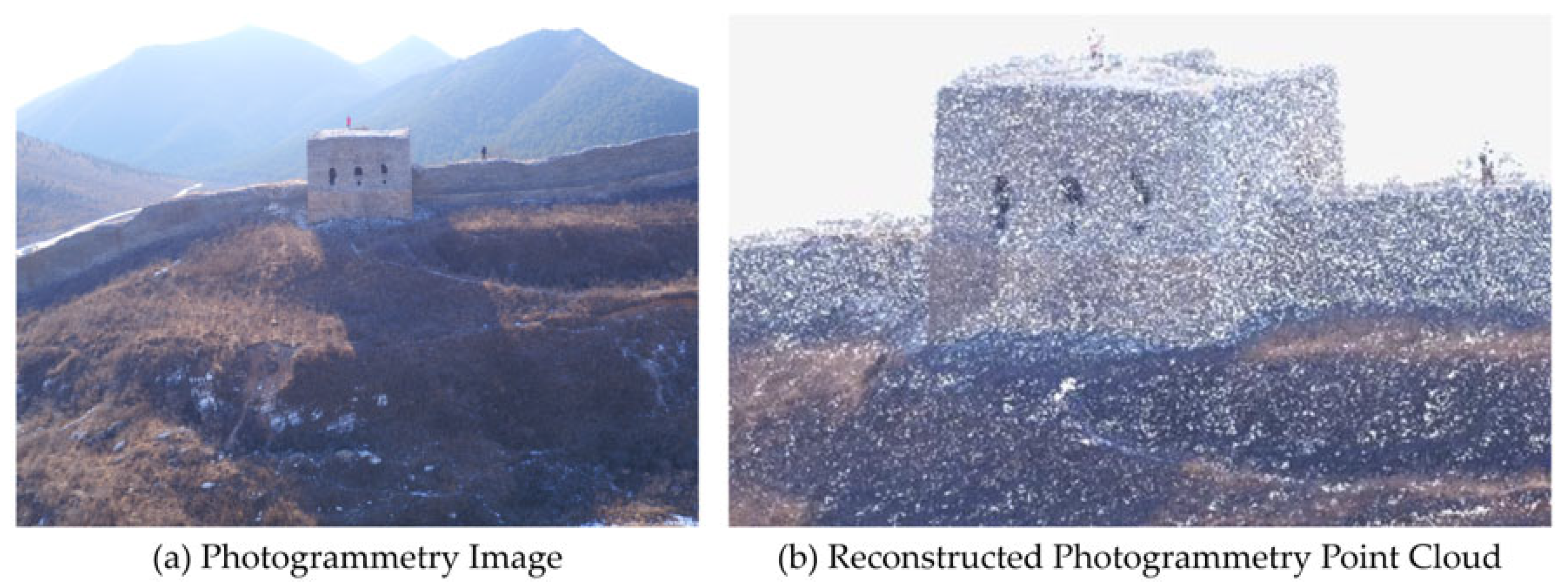
As depicted in Figure 9, Figure 10 and Figure 11, a sample image of the Great Wall is presented alongside the corresponding reconstructed 3D point cloud and model using a photogrammetry-based method. A comparison with the proposed depth camera-based method reveals that the 3D model obtained from photogrammetry lacks sufficient detail and realism. Furthermore, the photogrammetry-based method is constrained by high economic and labor costs, as well as no-fly zone restrictions for drones, which limit its practicality. In contrast, the proposed method exhibits significant advantages in both practical application and efficacy.

5. Conclusions

Aiming to protect the Great Wall in the Juyongguan area, this paper proposed a 3D reconstruction framework and handheld equipment to investigate data collection and refined 3D modeling of architectural heritage. The following four conclusions can be drawn: (1) Handheld equipment can improve the efficiency and accuracy of measurement and collection, save economic and labor costs, and avoid secondary damage to architectural heritage. (2) Real-time and automatic information processing can avoid tedious manual data arrangement; in this process, the blind area of the view angle can be observed in time to carry out supplementary acquisition. (3) The comprehensive and fine modeling of buildings can be realized with the use of UAV tilt photography technology [28]. (4) The collected data can be used for 3D model generation in the common output format and be processed in open-source software, such as CloudCompare and MeshLab.
Under the rapid development of digital technology, 3D scanning and point cloud intelligent processing comply with the needs of the times. Using a big data platform that integrates real-time acquisition, transmission, and information extraction of multi-source data is the future development direction. Firstly, this platform can provide accurate building measurement data and digital models to optimize building design and the construction process and provide practical tools for later maintenance and management. Secondly, visualization and interactive display, 3D reconstruction technology, and virtual reality technology are united to realize design solution visualization and provide customers with a more immersive and interactive experience. Finally, 3D reconstruction technology can be combined with artificial intelligence and big data to realize the intelligent management of buildings.

Author Contributions

Methodology, L.X.; software, Y.X.; data acquisition and processing, Z.R. and W.G.; writing—original draft preparation, L.X.; writing—review and editing, L.X. and Y.X.; funding acquisition, L.X. All authors have read and agreed to the published version of the manuscript.

Funding

This research was funded by the Fundamental Research Funds for the Central Universities, grant number 2022RCW007.

Institutional Review Board Statement

Not applicable.

Informed Consent Statement

Not applicable.

Data Availability Statement

The datasets presented in this article are not readily available due to policy and qualification restrictions.

Conflicts of Interest

The authors declare no conflicts of interest.

References

  1. Zhang, L.; Li, C.; Ruan, C. Application of 3D Laser Scanning Technology in Building Elevation Surveying and Mapping. Urban Geotech. Investig. Surv. 2023, 1, 144–147. [Google Scholar]
  2. Ali, S.; Omar, N.; Abujayyab, S. Investigation of the accuracy of surveying and buildings with the pulse (non prism) total station. Int. J. Adv. Res. 2016, 4, 1518–1528. [Google Scholar]
  3. Thoeni, K.; Giacomini, A.; Murtagh, R.; Kniest, E. A comparison of multi-view 3D reconstruction of a rock wall using several cameras and a laser scanner. Int. Arch. Photogramm. Remote Sens. Spat. Inf. Sci. 2014, 40, 573–580. [Google Scholar] [CrossRef]
  4. Zhao, Z.H.; Sun, H.; Zhang, N.X.; Xing, T.H.; Cui, G.H.; Lai, J.X.; Liu, T.; Bai, Y.B.; He, H.J. Application of unmanned aerial vehicle tilt photography technology in geological hazard investigation in China. Nat. Hazards 2024, 6, 1–32. [Google Scholar] [CrossRef]
  5. Lerma, J.L.; Navarro, S.; Cabrelles, M.; Seguí, A.E.; Haddad, N.; Akasheh, T. Integration of laser scanning and imagery for photorealistic 3D architectural documentation. In Laser Scanning, Theory and Applications; IntechOpen: London, UK, 2011; pp. 414–430. [Google Scholar]
  6. Fais, S.; Cuccuru, F.; Ligas, P.; Casula, G.; Bianchi, M.G. Integrated ultrasonic, laser scanning and petrographical characterisation of carbonate building materials on an architectural structure of a historic building. Bull. Eng. Geol. Environ. 2017, 76, 71–84. [Google Scholar] [CrossRef]
  7. Zeng, P.; Liu, C.L. Research and Engineering Practice of Building Elevation Measurement Method Combining 3D Laser Scanning and Total Station. Urban Geotech. Investig. Surv. 2018, 168, 139–142. [Google Scholar]
  8. Sharma, O.; Arora, N.; Sagar, H. Image Acquisition for High Quality Architectural Reconstruction. Graph. Interface 2019, 18, 1–9. [Google Scholar]
  9. Gao, G. Study on the application of multi-angle imaging related technology in the construction process. Appl. Math. Nonlinear Sci. 2024, 9, 3. [Google Scholar] [CrossRef]
  10. Sun, Z.; Cao, Y.; Zhang, Y. Applications of Image-based Modeling in Architectural Heritage Surveying. Res. Herit. Preserv. 2018, 3, 30–36. [Google Scholar] [CrossRef]
  11. Wang, W.; Peng, F.; Li, J.; Chen, S. Research on 3D Reconstruction and Utilization of Historic Buildings Based on Air-Ground Integration Surveying Method: A Case of the Former Residence of Kim Koo on Chaozong Street in Changsha. Urban. Archit. 2022, 19, 135–142. [Google Scholar] [CrossRef]
  12. Liu, C.; Zeng, J.; Zhang, S. True 3D Modelling Towards a Special-shaped Building Unit by Unmanned Aerial Vehicle with a Single Camera. J. Tongji Univ. Nat. Sci. 2018, 46, 550–556. [Google Scholar]
  13. He, Y.; Chen, P.; Su, Z. Ancient Buildings Reconstruction based on 3D Laser Scanning and UAV Tilt Photography. Remote Sens. Technol. Appl. 2019, 34, 1343–1352. [Google Scholar]
  14. Li, R. Mobile mapping: An emerging technology for spatial data acquisition. Photogramm. Eng. Remote Sens. 1997, 63, 1085–1092. [Google Scholar]
  15. Liu, K. Application of 3D Laser Geometric Information Acquisition Based on the Protection and Repair Requirements of Ancient Buildings. Ph.D. Thesis, Beijing University of Technology, Beijing, China, 2019. [Google Scholar]
  16. Murtiyoso, A.; Grussenmeyer, P.; Suwardhi, D. Technical considerations in Low-Cost heritage documentation. Int. Arch. Photogramm. Remote Sens. Spat. Inf. Sci. 2019, 42, 225–232. [Google Scholar] [CrossRef]
  17. Krátký, V.; Petráček, P.; Nascimento, T.; Čadilová, M.; Škobrtal, M.; Stoudek, P.; Saska, M. Safe documentation of historical monuments by an autonomous unmanned aerial vehicle. ISPRS Int. J. Geo Inf. 2021, 10, 738. [Google Scholar] [CrossRef]
  18. Zhang, Q. 3D Reconstruction of Large Scene Based on Kinect. Master’s thesis, University of Electronic Science and Technology of China, Chengdu, China, 2018. [Google Scholar]
  19. Ng, P.C.; Henikoff, S. SIFT: Predicting amino acid changes that affect protein function. Nucleic Acids Res. 2003, 31, 3812–3814. [Google Scholar] [CrossRef] [PubMed]
  20. Zheng, Y.; Kuang, Y.; Sugimoto, S.; Astrom, K.; Okutomi, M. Revisiting the pnp problem: A fast, general and optimal solution. In Proceedings of the IEEE International Conference on Computer Vision, Sydney, NSW, Australia, 2–8 December 2013; pp. 2344–2351. [Google Scholar]
  21. Triggs, B.; McLauchlan, P.F.; Hartley, R.I.; Fitzgibbon, A.W. Bundle adjustment—A modern synthesis. In Proceedings of the Vision. Algorithms: Theory and Practice: International Workshop on Vision, Algorithms, Corfu, Greece, 21–22 September 1999; pp. 298–372. [Google Scholar]
  22. Shi, L.; Hou, M.; Hu, Y. Research on 3D Representation Method of Ancient Architecture Based on Point Cloud Data and BIM. Res. Herit. Preserv. 2018, 3, 46–52. [Google Scholar] [CrossRef]
  23. Vizzo, I.; Guadagnino, T.; Behley, J.; Stachniss, C. Vdbfusion: Flexible and efficient tsdf integration of range sensor data. Sensors 2022, 22, 1296. [Google Scholar] [CrossRef]
  24. Li, Z.; Huang, S.; Zhang, M.; Li, Y. The Method of Rapid Acquisition of Facade Image and Intelligent Retrieval of the Decoration Category of Traditional Chinese Rural Dwellings: A Case Study on the Decorative Style of the Residential Entrance of Liukeng Village. Zhuangshi 2019, 16–20. [Google Scholar] [CrossRef]
  25. Wang, B.; Xu, X. Beijing Diming Dian; China Federation of Literary and Art Circles Publishing Corporation: Beijing, China, 2001. [Google Scholar]
  26. Zhang, Y.; Zhang, Y.; Chen, X. Research on Key Technology of 3D Laser Scanning in Surveying and Mapping of Ancient Buildings. Archit. J. 2013, S2, 29–33. [Google Scholar]
  27. Wu, Y.; Zhang, Y. Survey on the Standard of the Application of 3D Laser Scanning Technique on the Cultural Heritage’s Conservation. Res. Herit. Preserv. 2016, 1, 1–5. [Google Scholar] [CrossRef]
  28. Sun, Z.; Cao, Y. Accuracy Evaluation of Architectural Heritage Surveying from Photogrammetry Based on Consumer–Level UAV–Born Images: Case Study of the Auspicious Multi-door Stupa. Herit. Archit. 2017, 4, 120–127. [Google Scholar]
Figure 1. The overall framework of 3D reconstruction based on a depth camera.
Sustainability 16 07024 g001
Figure 2. Collection routes for the architectural remains of the Great Wall.
Sustainability 16 07024 g002
Figure 3. Depth image, IR grayscale image, and RGB color image (computer screenshot).
Sustainability 16 07024 g003
Figure 4. Wearable depth camera 3D reconstruction integrated acquisition device and principal schematic.
Sustainability 16 07024 g004
Figure 5. The point cloud office processing process and results of north facade of the No.3 watching tower of the Juyongguan Great Wall.
Sustainability 16 07024 g005
Figure 6. The point cloud office processing process and results of west facade of the No.3 watching tower of the Juyongguan Great Wall.
Sustainability 16 07024 g006
Figure 7. The processing results of the Juyongguan Great Wall’s interior wall point cloud.
Sustainability 16 07024 g007
Figure 8. The vectorized result of the 3D model of the current status of the enemy tower at the Juyongguan Great Wall.
Sustainability 16 07024 g008
Figure 9. An example of a photogrammetry image and reconstructed point cloud of the Great Wall in the Xuliukou area.
Sustainability 16 07024 g009
Figure 10. An example of a 3D model of the Great Wall in the Juyongguan area generated using the photogrammetry-based method.
Sustainability 16 07024 g010
Figure 11. Rendered images from different perspectives of the Juyongguan 3D model obtained using the photogrammetry-based method.
Sustainability 16 07024 g011
Table 1. A comparison of the three measurement techniques for historic buildings.
AspectPropertiesPrism-Free Total Station Measurement TechnologyGround Close-Up Multi-View Photography TechnologyUAV Tilt Photography Technology
Data acquisition costOperation costUSD 600–4000 USD 800–5000USD 1000–10,000
LowerLowHigh
PortabilityPoorGoodGood
Acquisition timeLongShortShort
Modeling timeLongLongShort
Mapping spatial locationRoofInconvenient collectionConvenient collectionConvenient collection
IndoorInconvenient collectionInconvenient collectionInconvenient collection
Mapping environmental requirementsDependence on distanceDependenceIndependenceIndependence
Dependence on lightDependenceDependenceIndependence
Dependence on weatherDependenceDependenceDependence
Data error analysis3D informationIndirect acquisitionIndirect acquisitionDirect acquisition
AccuracyMillimeter-levelBig errorat centimeter level
Source of errorLimited by the laser beam, the ranging effect of corners or dark objects is not idealComplexity of scene structure, image overlap rateLayout of image control points, image quality, image overlap, and flight height
DetailsGeneralGoodGood
MaterialNoYesYes
Table 2. Time efficiency of 3D reconstruction.
Data BagData Acquisition LocationData Acquisition Range (m)Data Acquisition Time (s)Reconstruction
Time (s)
Reconstruction
Speed (s/m)
1Nankou Town3.52.811.33.23
2Mutianyu 7.56.025.43.39
3Shuiguan 9.57.630.93.25
4Xuliukou 10.58.434.23.26
5Juyongguan 15.512.450.43.25
Average-46.537.2152.23.27
Disclaimer/Publisher’s Note: The statements, opinions and data contained in all publications are solely those of the individual author(s) and contributor(s) and not of MDPI and/or the editor(s). MDPI and/or the editor(s) disclaim responsibility for any injury to people or property resulting from any ideas, methods, instructions or products referred to in the content.