Article

Applications of Novel Combined Controllers for Optimizing Grid-Connected Hybrid Renewable Energy Systems

by
Fatima Menzri
1,
Tarek Boutabba
2,3,
Idriss Benlaloui
3,*,
Larbi Chrifi-Alaoui
4,
Abdulaziz Alkuhayli
5,
Usama Khaled
6 and
Mohamed Metwally Mahmoud
6,*
1
LGEA Laboratory, Electrical Engineering Department, Science and Applied Science Faculty, L’arbi Ben M’hid Oum Bouaghi University, Oum Bouaghi 04000, Algeria
2
LSPIE Laboratory, Faculty of Science and Technology, University of Khenchela, El-Hamma, BP 1252 Road of Batna, Khenchela 40004, Algeria
3
Laboratory of Electromagnetic Induction and Propulsion Systems (LSPIE), Department of Electrical Engineering, Faculty of Technology, University of Batna 2, Batna 05000, Algeria
4
LTI Laboratory of Innovative Technologies, University of Picardie Jules Verne, LTI (EA, 3899), 13 F. Mitterrand Avenue, 02880 Cuffies, France
5
Department of Electrical Engineering, College of Engineering, King Saud University, Riyadh 11421, Saudi Arabia
6
Electrical Engineering Department, Faculty of Energy Engineering, Aswan University, Aswan 81528, Egypt
*
Authors to whom correspondence should be addressed.
Sustainability 2024, 16(16), 6825; https://doi.org/10.3390/su16166825
Submission received: 23 April 2024 / Revised: 25 July 2024 / Accepted: 27 July 2024 / Published: 9 August 2024

Abstract

:
Hybrid renewable energy systems (HRES) integrating solar, wind, and storage technologies offer enhanced efficiency and reliability for grid-connected applications. However, existing control methods often struggle with maintaining DC voltage stability and minimizing power fluctuations, particularly under variable load conditions. This paper addresses this research gap by proposing a novel control strategy utilizing a PD (1+PI) regulator that combines proportional–integral (PI) and proportional–derivative (PD) controllers. Integrated into the HRES with maximum power point tracking (MPPT), the system includes solar panels, a storage unit, and a wind system featuring a permanent magnet synchronous generator (PMSG). The PD (1+PI) regulator plays a critical role in stabilizing DC voltages within the storage system and collaborates with predictive direct power control (P-DPC) to improve current quality by mitigating fluctuations in active and reactive power. Comparative analysis against traditional direct power control methods shows that the proposed strategy reduces voltage fluctuation by 30% and improves energy utilization efficiency by 25%, validating its efficacy in managing energy from diverse sources to meet nonlinear load demands. The results demonstrate that integrating the PD (1+PI) regulator with MPPT and P-DPC approaches enhances power stability and optimizes energy utilization in grid-connected HRES, underscoring the effectiveness of this advanced control system.

1. Introduction

The adoption of new and renewable energy sources (RESs) has become increasingly evident due to rising electricity demand and the gradual depletion of fossil fuel reserves [1,2,3]. These resources offer a clean, environmentally acceptable alternative to fossil fuels and provide a sustainable solution to our energy needs. Innovative research supports these efforts: Ref. [3] explore housing envelope thermal performance as passive cooling systems, showcasing advancements in sustainable building technologies. Ref. [4] studied PCM solar walls under varying natural conditions, and ref. [5] contributed to understanding innovative RES technologies and their practical applications in building design and energy efficiency.
Combining multiple energy sources into hybrid RESs (HRESs) is crucial to enhancing energy output consistency and mitigating the intermittent nature of renewables [6,7]. Photovoltaics (PV) are particularly noteworthy, constituting 36% of RESs for power generation in 2018 [8], due to their widespread availability, operational reliability, and efficiency.
In the field of RESs, the integration of varied energy sources is crucial for increasing dependability and improving energy output. Ref. [5] underscored the crucial role of demand-side management techniques and energy storage systems in ensuring the financial viability of renewable energy-based distribution networks. Effective control systems are essential for regulating energy flow within HRES, as highlighted by their study. Concurrently, Ref. [9] emphasizes the impact of harmonic losses in distributed solar systems integrated with low-voltage distribution networks, stressing the need for efficient control strategies to maintain energy quality and grid stability. Ref. [10] contributed insights into the significance of advanced control techniques in optimizing energy use and ensuring grid compatibility, particularly in hybrid PV-battery systems.
Advanced control strategies play a critical role in optimizing grid-connected photovoltaic (PV) systems. Refs. [11,12] have explored methodologies such as maximum power point tracking (MPPT) and active/reactive power control, essential for improving energy extraction efficiency and stabilizing system operation. MPPT techniques ensure PV systems operate at peak efficiency by continuously adjusting module operating points to maximize output power. Additionally, ref. [13] proposed a simplified super-twisting algorithm tailored for PV systems, aiming to mitigate total harmonic distortion (THD) and enhance operational efficiency. THD reduction is crucial for maintaining the power quality and operational smoothness of grid-connected equipment. Reactive power compensation provided by their algorithm helps balance power factors, reducing losses and enhancing overall system efficiency. Similarly, ref. [14] underscored the importance of advanced algorithms in optimizing energy consumption and adapting to dynamic grid conditions, thus ensuring sustainable and efficient energy use.
Moreover, ref. [15,16] introduced a novel algorithm-based approach for optimizing the sizing of stand-alone hybrid energy systems. This advancement significantly improves RES modeling and control strategies, enhancing system performance, reliability, and sustainability. Together, these studies underscore the critical role of advanced control strategies and optimization techniques in enhancing the efficiency, stability, and reliability of RESs. Building on these foundations, the proposed PD (1+PI) regulator in this study offers a robust solution to manage voltage and current errors in hybrid systems connected to the grid, while leveraging MPPT techniques for optimal energy extraction.
Furthermore, the integration of Li-Ion batteries with grid-connected doubly fed induction generator (DFIG) wind turbines, as explored in [16,17], contributes to smoothing intermittent power output, ensuring a stable and reliable energy supply. The bidirectional DC–DC converter plays a crucial role in managing battery charging and discharging processes, optimizing energy flow between wind turbines and the grid. This bidirectional functionality enhances overall system reliability and performance, demonstrating the pivotal role of energy storage in enhancing HRES efficacy.
This study introduces a novel control strategy aimed at enhancing energy management and stability in grid-connected HRES. Using recent developments in control theory and RES modeling, the method integrates a PD (1+PI) controller to reduce voltage and current fluctuations in PV and wind systems, thereby improving the efficiency of MPPT. Additionally, it optimizes battery charging and discharging using the PD (1+PI) controller and enhances grid performance through a P-DPC-PD (1+PI) approach. By incorporating advanced control algorithms and energy storage systems, the strategy aims to boost the effectiveness, reliability, and lifetime of renewable energy systems. MATLAB simulations results confirm the comprehensive energy optimization methodology, highlighting avenues to improve sustainability and reliability.
Our research study is organized as follows: Section 1 provides detailed mathematical models for system components, focusing on integrating the PD (1+PI) controller to stabilize voltage and current in PV and wind systems. Section 2 establishes the theoretical framework by explaining how the PD (1+PI) controller integrates with MPPT and P-DPC techniques. Section 3 conducts an analysis of THD and presents a comparative study with recent approaches. Section 4 presents simulation results, including RES and grid analyses, alongside a comparative study with recent research to validate the efficacy of the proposed PD (1+PI) controller strategy. Finally, Section 5 concludes with a comprehensive discussion on the implications of these findings and proposes future research directions to optimize grid-connected HRES performance.

2. Design of the Proposed System

A hybrid system connected to a grid is depicted in Figure 1. The primary energy sources for this hybrid system are solar and wind power, with an energy storage system acting as a backup. By controlling the processes involved in charging and discharging batteries, the energy storage system supports the primary system. The primary objective of this research is to suggest a control method with a focus on improving energy quality for energy produced from different energy sources that are specified in the system approach. We can achieve this through tracking the energy produced by the PV and wind systems at their MPPTs and making sure the energy storage system operates when needed.

2.1. Mathematical Modeling of the Proposed System

2.1.1. PV System

The equivalent circuit and mathematical model of a single−diode PV cell are shown in Figure 2. This model has series and shunt resistances as well as a current generator that is coupled in series with a diode [18,19].
The relationship between the PV cell’s characteristic (the current-voltage I−V), as mentioned in [20,21] is expressed by the following equation:
I p v = N p I p h N p I o exp q ( V p v + N s N p R s I p v N s A K T 1 V p v + N S N P R s I p v N s N p R s h
These formulas can be used to express the reverse saturation current and photo current:
I p h = I s c + K i T + T r e f G G r e f
I o = I r e s T T r e f 3 exp q E g A K 1 T r e f 1 T

2.1.2. Wind System

The model for the generation of wind energy has been provided in [22,23]. The permanent magnet synchronous generator (PMSG) of a wind turbine is used to transform mechanical energy in the wind system into electrical energy. To supply a DC bus voltage, this system relies on the use of an AC/DC inverter and a DC/DC boost converter. In addition, AC voltage is converted into DC voltage using an AC/DC rectifier. A DC/DC boost converter, which controls energy production at the MPPT’s maximum power point, is coupled to this DC voltage during that process. The following equations [24,25] can be used to characterize the three characteristics of a wind generator: mechanical power (Pm), mechanical torque (Tm), and tip speed ratio (TSR):
P m = 1 2 ρ S C p λ , β V w i n d 3
C p λ , β = C 1 C 2 1 λ i C 3 β C 4 e C 5 λ i + C 6 λ
C1 = 0.5176; C2 = 116; C3 = 0.4; C4 = 5; C5 = 21; C6 = 0.0068: Values of the coefficients C1 to C6, respectively, and λi are given in [26,27]:
According to Newton’s second law, the acceleration force is the force that will apply a linear acceleration to the vehicle [28,29].
1 λ i = 1 λ + 0.08 β 0.035 β 3 + 1
The tip speed ratio of the wind turbine is defined as follows:
λ = W r R V w i n d
The mechanical torque Tm of the wind turbine defined by the following [30,31]:
T m = P m W r

2.1.3. Battery Storage System

The benefits of NiMH batteries include low cost, great energy density, and less chance of memory effect. They do have certain disadvantages, though, including a low internal impedance, a fast self-discharge rate, and a restricted capacity to withstand overcharging. Despite these drawbacks, they are essential to the system since they supply electricity when primary sources like wind and photovoltaics are not accessible. They also store extra energy produced by these sources [32,33]. As shown in Figure 3, a bidirectional DC/DC converter makes this function possible.
A bi-directional converter that regulates the DC link voltage at 500V connects the battery storage to the DC bus voltage. Based on the state of charge (SOC), the bi-directional controller controls the two switching pulses (S1 for charging and S2 for discharging). According to research, a battery is considered to be fully charged when its condition falls between 20% and 80% [34]. The battery SOC level gives the energy reserve status given by percentage as follows:
SOC = 100 1 - i b Q dt

2.1.4. Boost Converter DC/DC

To connect the energy sources to the DC link, we used a boost converter DC/DC. This eventually allowed us to use MPPT control to increase the energy output. As shown in the comparable circuit Figure 4 [35,36], the DC voltage level is first established using a boost converter, and then it is determined using an equation that shows the relationship between the input and output voltages.
V o u t = V i n 1 D
The boost converter can be described in two sets of state equation depending on the duty cycle [36]:
d i l d t = 1 l V i n V o u t 1 D
d V o u t d t = 1 C i l 1 D i l o a d

3. Control and Improvement Power of HRES

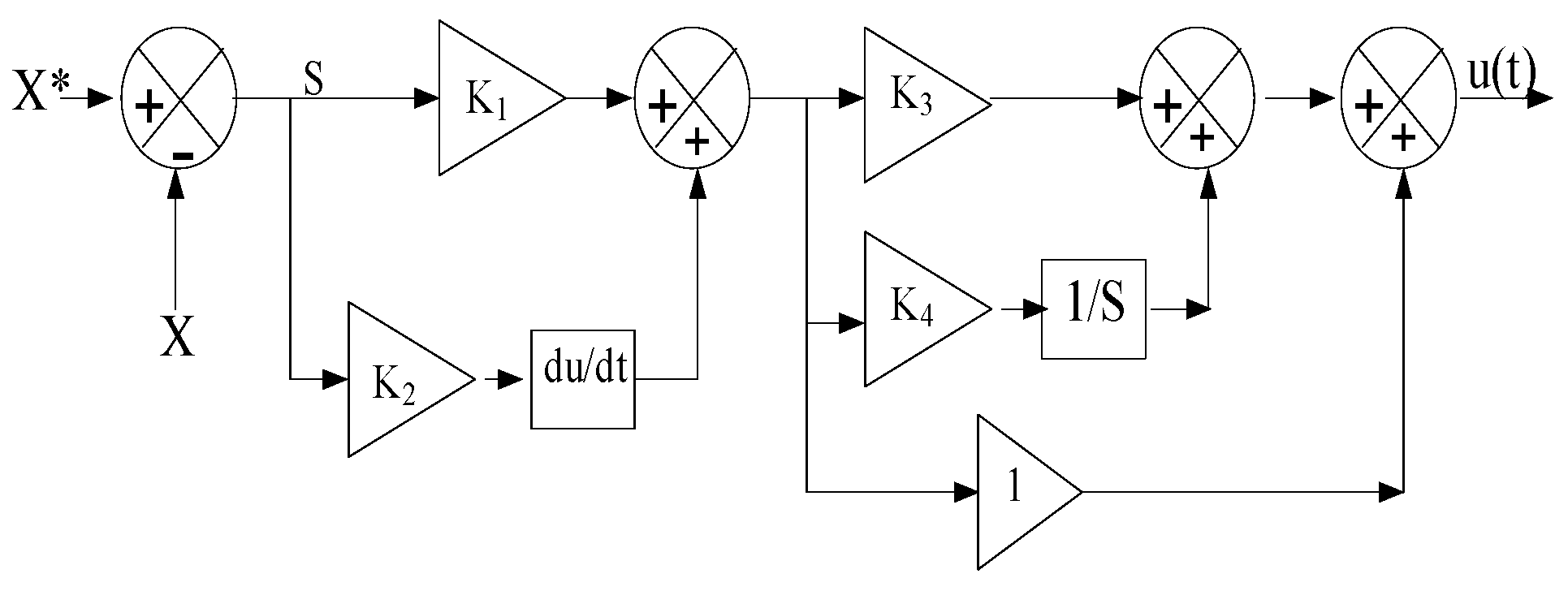
3.1. PD(1+PI) Controller

Due to their affordability, simplicity, and ease of use in comparison with other types, the proportional (P), proportional–integral–derivative (PID), and proportional–derivative (PD) controllers are widely known and utilized in industrial areas. An overview of the characteristics and differences throughout PI, P, PID, and PD controllers can be found in Table 1. These controllers are used in a variety of techniques, such as vector control [37], field-oriented control (FOC) [37], direct torque control (DTC) [38], and direct power control (DPC) [4]. Equation (13) can be used to express these controller types.
u 1 ( t ) = K i 0 t S . d t + K p . S U 2 ( t ) = K d d S ( t ) d t + K p . S u 3 ( t ) = K i 0 t S . d t + K p . S + K d d S ( t ) d t
Equation (10) depicts the controller introduced in this section of the paper [16]:
w ( t ) = K 1 . S + K 2 d S ( t ) d t 1 + K 3 . S + K 4 0 t S . d t
where, K1, K2, K3, and K4 are the constants gains, and S is the surface or error
( S = X * X )
The transformation function that represents this controller is expressed in Equation (15). Additionally, Figure 5 illustrates the principle of the controller proposed in this paper, aiming to minimize fluctuations in voltage, torque, current, and active power. Moreover, it contributes to the reduction of the steady−state error.
w ( t ) S ( t ) = ( K 4 + S + K 3 . S ) ( K 1 + K 2 )

3.1.1. The Proposed MPPT-PD (1+PI) for PV Generator

In order to maximize power extraction, the DC–DC boost converter is frequently used in solar PV systems to increase and control the PV panel’s voltage to a predefined level. The setup combining the MPPT approach and PD(1+PI) control is shown in Figure 6.
The reference voltage value was obtained using the perturb and observe (P&O) technique, which is discussed in [11,39]. Equation (16) was then used to compare the result with the PV generator’s predicted voltage.
e V p v = V p v * V p v
The PD(1+PI) controller is in charge of producing the inductance reference current and controlling the PV voltage (Vpv). Equation (17) illustrates how this method generates the duty cycle for the DC/DC boost converter and guarantees the lowest possible level of steady-state error in the inductance current regulation:
u ( t ) = K 1 . e v p v + K 2 d e v p v ( t ) d t + 1 + K 3 . e v p v + K 4 0 t e v p v d t

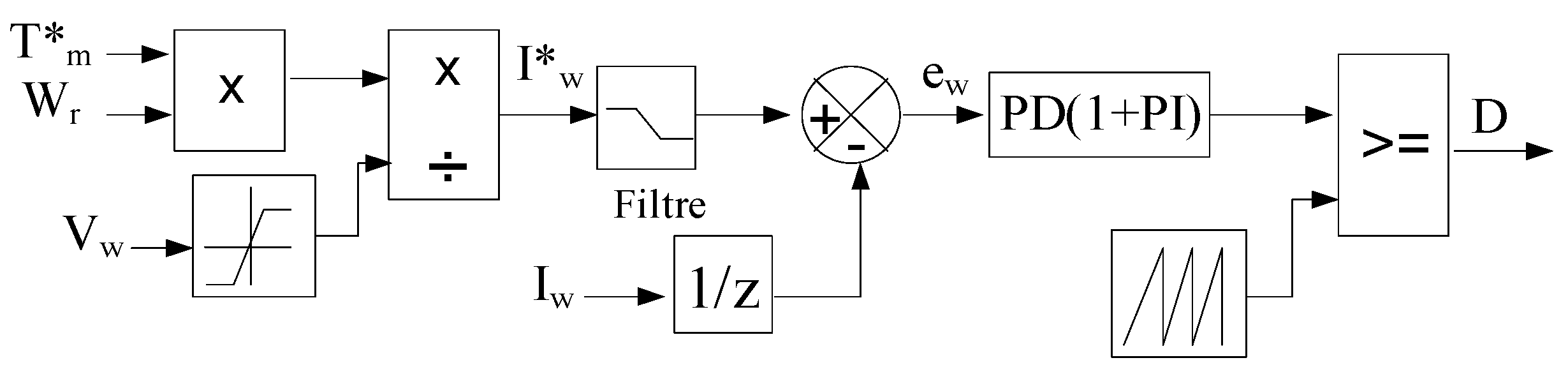
3.1.2. The Proposed MPPT-PD (1+PI) for Wind Generator

The wind generator has been integrated into the smart grid as an additional energy source. Due to the variable nature of the system, a control unit has been proposed to track the maximum power point and enhance the quality of the generated energy. This is achieved by integrating the control unit to adjust the current error value for the wind generator, which, in turn, is modified based on the reference value for the current derived from the reference torque value as shown in Figure 7:
The reference value of the rotor speed (Wr*) is extracted using the algorithm mentioned in [14,40] followed by the calculation of the reference mechanical torque (Tm*) for the wind generator using Equation (18).
T m * = p m w r *
The reference wind current (Iw) is calculated by dividing the reference value of mechanical torque (Tm*) in Equation (21) by Vw as follows:
I w * = T m * . W r V w
The error in tracking the current of the wind generator is defined as follows:
e w = I w * I w
where the duty cycle of the DC–DC boost converter presents as in Equation (21):
u ( t ) = K 1 . e w + K 2 d e w ( t ) d t + 1 + K 3 . e w + K 4 0 t e w d t

3.1.3. Buck/Boost Converter Control Using PD(1+PI) for Battery System

The local control unit for storage adjusts the battery current to manage the charging and discharging of the battery by supplying a duty cycle to the converter, as illustrated in Figure 1, thus ensuring the power balance of the hybrid microgrid and maintaining a stable DC bus voltage.
The net power in the system (Pnet) can be calculated as follows (22):
P n e t = P l ( P g + P p v + P w )
where Pnet: battery power, Pl: non-linear load power, Pg: grid power, Ppv: solar power, Pw: wind power.
The reference battery current (ib) is calculated by dividing Pnet in Equation (23) by Vb as follows:
i b * = P n e t v b
The error in tracking the current of the battery is defined as follows:
e i b = i b * i b
where the error in tracking the DC-link voltage is defined as follows (25):
e v d c = v d c * v d c
The inductor current is regulated with minimum steady-state error and generates the duty cycle of the buck–boost converter as shown in Equation (26):
D = e i d c e i b
While maintaining the state of the charge (SOC) as illustrated in the Figure 7 (20% < SOC < 80%).

3.2. Grid Control Side

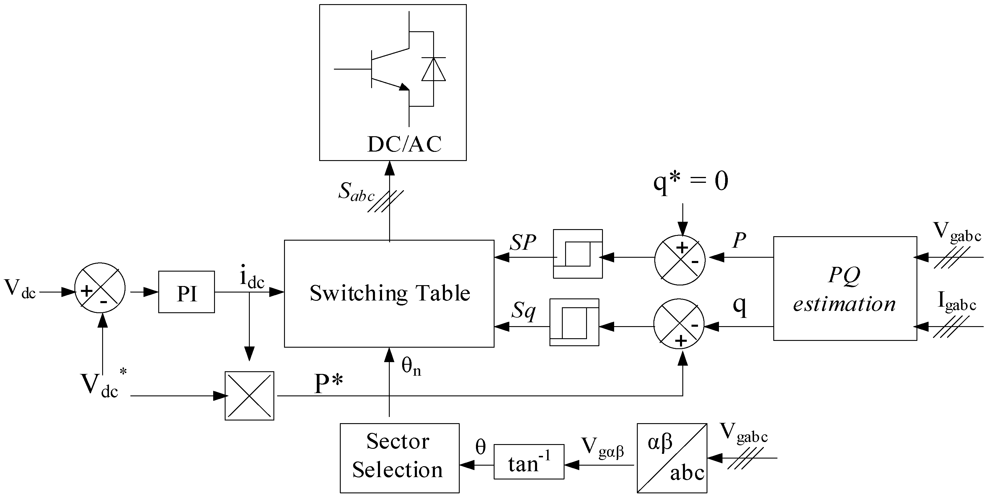
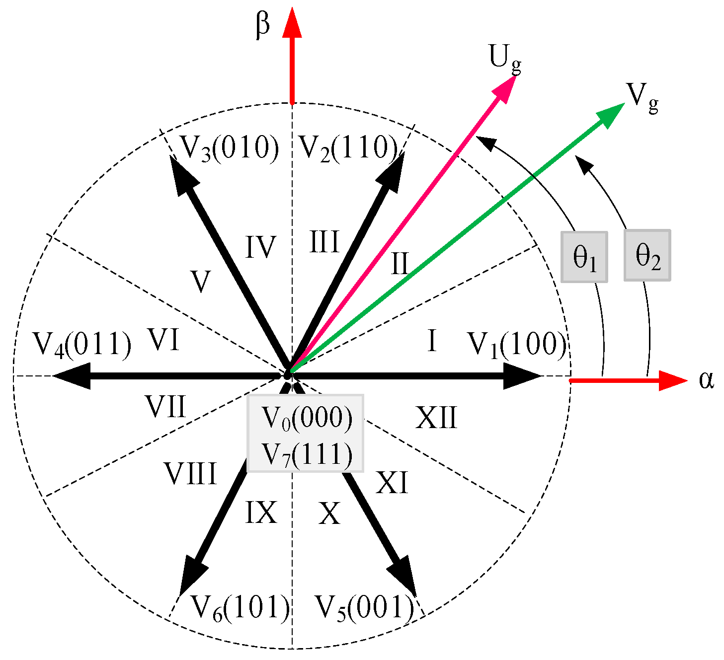
3.2.1. Classical Direct Power Control Strategy (PI-DPC)

DPC concept is based on the use of predefined “voltage vectors”, which are specified in a “switching table” and applied to the 3-phase PWM converter [14,41]. These voltage vectors correspond to sequences of switching states for the converter switches, namely “Sa, Sb, Sc” as presented in Figure 8. The selection of these vectors is determined by evaluating the discrepancies (Sp, Sq) between the desired references (P*, q*) and the actual measured values (P, q) of both “active power” and “reactive power”. Additionally, the selection process considers the angular position θ of the flux vector for the rotor side converter (RSC) and the grid voltage vector for the grid side converter (GSC) [42].
The concept of DPC is visually presented in Figure 7. It relies on the comparison between the instantaneous reference values of active and reactive powers and their corresponding measurements. These comparisons are used as inputs for two hysteresis comparators. They, in conjunction with the switching table and the grid voltage magnitude, determine the switching states of the switches. Furthermore, a PI controller is employed to regulate the voltage of the DC bus [43].
The electrical grid supplies three-phase voltages (Vg) utilizing L-filter inductances and resistances as shown in Figure 9. When transforming the three-phase mathematical model into a two-phase stationary frame, the PWM rectifier model can be represented as follows [44]:
V g = R i g + L g d i g d t + V r e c
Here, Vg and ig represent the grid voltage and current vectors, respectively, while vrec denotes the rectifier voltage vector.
V g = 2 3 V a + V b e j ( 2 π / 3 ) + V c e j ( 4 π / 3 )
i g = 2 3 i a + i b e j ( 2 π / 3 ) + i c e j ( 4 π / 3 )
v r e c = 2 3 V d c S a + S b e j ( 2 π / 3 ) + S c e j ( 4 π / 3 )
Vdc: is the DC-link voltage.
The rectifier control is based on the logic values Si, where: Si = 1, Ti is ON, and Ti is OFF. Si = 0, Ti is OFF and Ti is ON with: i = a, b, c.
It is a well-established fact that the calculation of “active” power “P” involves a “scalar” product between “voltages” and “currents”, while the determination of “reactive” power “q” can be achieved through a “vector” product between them [45].
P = V a i a + V b i b + V c i c
q = 1 3 V b V c i a + V c V a i b + V a V b i c
The instantaneous discrepancies in active and reactive powers are transformed into logic outputs, Sp and Sq, employing two two-level hysteresis comparators. If the error surpasses or falls below a specified band, the hysteresis output will assume states 1 or 0, respectively. When the errors fall within the acceptable range, the output remains unchanged. Thus, for hysteresis bands HP and Hq corresponding to active and reactive powers, the outputs of the hysteresis comparators are as follows:
S p = 1 i f P < P * H p S p = 1 i f P > P * + H p ; w h e r e   P * = V d c * . i d c
S q = 1 i f q < q * H q S q = 1 i f q > q * + H q ; w h e r e   q * = 0
Note: The reference active power P* is determined by a proportional–integral (PI) regulator controlling the DC voltage, while the reactive power q* is set to zero to ensure operation under the unity power factor.
To enhance precision and address issues that may arise at the boundaries of each control vector, the vector space is subdivided into twelve sectors, each spanning 30°.
Based on the outputs of the hysteresis comparators Sp and Sq, and corresponding to the sector in which the voltage vector is situated, the selection of the voltage vector to be applied to the rectifier is determined according to the subsequent switching table.

3.2.2. Proposed PD(1+PI)-P-DPC Strategy

In the existing topology, the P-DPC technique illustrated in Figure 10 is devised for the regulation of both active and reactive power levels exchanged with the grid [46]. Additionally, it aims to compensate for undesired harmonic contents in the grid current by appropriately tuning the reference active Power P* by integrating the PD(1+PI) controller. The fundamental concept behind this technique involves the minimization of a cost function, computed as the sum of squared differences between actual and predicted values of both active and reactive power [47].
To implement this strategy, the initial step involves establishing a predictive model for the voltage inverter using instantaneous power quantities, as elucidated by the approach in α-β reference frame [48]. In this reference frame, the active and reactive power levels exchanged with the grid are expressed as follows:
P = i α . e α + i β . e β q = i α . e β + i β . e α
Assuming a sufficiently small sampling time Ts (Ts << T), the synthesis of active and reactive power at the subsequent sampling time can be expressed through the following equation:
P ( K + 1 ) q ( K + 1 ) = e α ( K ) e α ( K ) e β ( K ) e β ( K ) . i α ( K + 1 ) i β ( K + 1 )
The changes in these magnitudes between two consecutive sampling moments are expressed as follows:
P ( K + 1 ) P ( K ) q ( K + 1 ) q ( K ) = e α ( K ) e α ( K ) e β ( K ) e β ( K ) . i α ( K + 1 ) i α ( K ) i β ( K + 1 ) i β ( K )
Moreover, disregarding the impact of the series resistance of the coupling inductance at the output of the inverter, the progression of the current vector is governed by a first-order differential equation:
d d t i α i β = 1 L f e α e β V α V β
Discretizing Equation (38) over a sampling period Ts yields the change in the current vector between two successive instances ‘k’ and ‘(k + 1)’, represented by the following equation:
i α ( K + 1 ) i α ( K ) i β ( K + 1 ) i β ( K ) = T s L f e α ( K ) e β ( K ) V α ( K ) V β ( K )
Substituting Equation (39) into Equation (36) results in the predictive model at the inverter output, relying on the instantaneous active and reactive powers [46], expressed as follows:
P ( K + 1 ) q ( K + 1 ) = P ( K ) q ( K ) + T s L f e α ( K ) e α ( K ) e β ( K ) e β ( K ) . e α ( K ) V α ( K ) e β ( K ) V β ( K )
As observed, the predictive model system involves only two parameters: the coupling inductance (Lf) and the sampling period (Ts). Ideally, the controlled quantities converge to their set values when the following condition is satisfied:
P * ( K + 1 ) P ( K + 1 ) = 0 q * ( K + 1 ) q ( K + 1 ) = 0
The condition stated in Equation (41) cannot be met unless the alterations in active and reactive power during the switching period assume the following values:
Δ P * ( K ) = P * ( K + 1 ) P ( K ) Δ q * ( K ) = q * ( K + 1 ) q ( K )
The calculated predicted reference values for active power, P⁄(k + 1) and reactive power, q⁄(k + 1) are determined as follows:
P * ( K + 1 ) = 2 . P * ( K ) P * ( K 1 ) q * ( K + 1 ) = q * ( K )
Thus, the optimal determination of the switching vector (Sa, Sb, Sc) is achieved by minimizing a quadratic cost function associated with errors in active and reactive power:
F = ε p ( K ) 2 + ε q ( K ) 2
where
ε p ( k ) = Δ P * ( K ) Δ P i ε q ( k ) = Δ q * ( K ) Δ q i i = 0 , 1 , , 6

4. Simulation Results

A PD (1+PI) controller was combined with the MPPT technology in order to reinforce the MPPT of the solar and wind power systems and to improve the power quality factor. Figure 1 and Figure 2 illustrate the results obtained, which validate the efficiency of the suggested method. These outcomes support this research paper’s proposed technology’s effectiveness.
(a)
RES analysis
Solar irradiation, PV current output, voltage, and power response are presented in Figure 11. Variations in the weather (solar irradiation) affect the dynamic characteristics of the solar power generator. Furthermore, the PV output voltage uses the P&O technique to obtain the reference value (Vpv*). Particularly, at 1000 W/m2 solar irradiation is when the generated energy reaches its maximum production level. This demonstrates how effectively the suggested approach tracks the MPP.
The wind power output and wind speed are shown in Figure 12. With wind speeds varying from 12 m/s to 6 m/s, it is obvious that the power generated varies with wind speed. It is also noticeable that the resultant energy is distortion-free and of excellent quality.
The results illustrate that the effectiveness of the PD (1+PI) controller could be combined with MPPT methods for RES generation that depend on solar and wind power.
(b)
Grid analysis
The active (a) and reactive (b) powers of the grid are shown, respectively, in Figure 13. The active power output response for the suggested and conventional techniques is shown in Figure 13a. When a PI-DPC controller is used instead of a PD (1+PI)-P-DPC controller, there are more ripples in the form; however, the power precisely matches the reference in both techniques. More ripples can be observed with the classical technique than with the suggested technique at times [0.8–1 s] and [1.6–1.7 s]. In addition, the recommended method provides an energy reaction time that is more effective than the PI controller.
Figure 14 and Figure 15 represent the first-phase grid voltage and three-phase grid currents output, respectively. Through these figures, the voltage and the currents take on a sinusoidal in the case of both the traditional and proposed strategies. Meanwhile, Figure 16 illustrates the pulse values for both the traditional and proposed strategies. It can be observed that the THD values reach 0.39% and 0.35% when using the traditional method during periods when the power grid intervened to meet demand requirements. However, with the proposed method, an improvement in THD values is noticeable, measured at 0.36% and 0.27%, respectively.
Figure 17 shows a DC-link voltage, and it appears that both methods result in voltages that are within the 600-volt reference range. On the other hand, the recommended approach provides more accurate findings with no distortion. For example, the ripples are much more apparent at 1 s, 1.05 s, 2.6 s, and nearly throughout the simulation time span when the traditional control scheme is used. This indicates that in order to align the DC voltage value with the reference value, the recommended method PD (1+PI) is required.
Figure 18 illustrates a power flow based on the PD (1+PI)-P-PDC technique. We have identified five modes for managing renewable energy in a grid-connected hybrid system, designed to supply a non-linear load under various climatic conditions:
Mode 01: It is clear that the photovoltaic system’s power generation is sufficient to meet up to a 10-kilowatt load requirement between [0 s and 0.5 s]. This can be represented as Ppv = Pl and does not require intervention from other production systems.
Mode 02: The energy demand increased from 0.5 s to 1 s, reaching 20 kW. This required the storage system to be discharged by approximately 9.9 kW in order to cover up for the production shortfall. This includes taking into account the fact that the photovoltaic system only produced roughly 10.1 kW, and the wind generator had no production at all because of the weather (extremely low wind speed). The formula for this is Pl = Ppv + Pb.
Modes 03 and 05: The renewable energy system was unable to supply the predicted load needs of 10 kW and 20 kW, respectively, within the time intervals [1–1.5 s] and [2.5–3 s]. The photovoltaic system could only produce 1000 watts or 2000 watts, respectively, due to the following weather conditions: solar irradiation of 100 W/m2 and 200 W/m2 and wind speed deficiency of 6 m/s and 2 m/s. Furthermore, the storage system could not discharge itself once more in order to keep the state of charge within the designated range (20% < SOC < 80%). This required the power grid to step in and cover the expected 9 kW to 18 kW of residual production, depending on the example analyzed. This situation can be expressed by Pl = Pg + Ppv.
Mode 04: With the wind speed reaching 12 m/s during the time period, we observed the wind generator contributing to the production of power with an estimated quantity of 6 kW. In the meantime, about 10 kW were produced by the photovoltaic system. Pl + Pb = Ppv + Pw is the extra energy that had to be charged into the storage system because the production exceeded the 6 kW demand.
(c)
Total harmonic distortion analysis
This study compares pulse values for proposed and conventional techniques in terms of THD as shown in Figure 16. The results show that the proposed method enhances power quality. The reduction ratio for the THD values decreased when solar irradiation equaled 1000 w/m2, while the conventional method had a lower reduction ratio. However, the proposed method had a higher reduction ratio, reaching 0.02% for solar generators and 0.01% for wind generators. As solar irradiation and wind speed increased, the reduction ratio in the THD current values also increased. The THD value for the direct current (DC link) decreased from 0.9% in the proposed method to 1.27% in the conventional method, and from 0.39% with the standard method to 0.27% with the proposed method. Table 2 lists the Comparative THD for the investigated systems.
This suggests that the proposed method is more successful in reducing harmonic distortion in grid voltage or current signals, ensuring grid stability and improving power quality. The observed drop in THD values demonstrates the effectiveness of the proposed strategy in improving power quality in renewable energy systems connected to the grid.
Table 3 presents quantitative analyses for the DC bus voltage, comparing the performance of the PD (1+PI) and PI control techniques across different time intervals.
  • Transient Time and Settling Time: The PD (1+PI) technique generally exhibits shorter settling times compared with the PI technique. For example, in the time interval of 0–0.5 s, the settling time for the PD (1+PI) technique is 0.2 s, whereas it is slightly longer at 0.22 s for the PI technique. This indicates that the PD (1+PI) technique achieves stability faster in response to transient changes in the system.
  • Ripple: The PD (1+PI) technique shows lower ripple values for the DC bus voltage compared with the PI technique. For instance, in the time interval of 0–0.5 s, the ripple for the PD (1+PI) technique is 0.07 volts, while it is slightly higher at 0.08 volts for the PI technique. This suggests that the PD (1+PI) technique produces a smoother and more consistent output voltage, which is desirable for stable operation.
  • Overshoot/Undershoot: Both techniques exhibit some level of overshoot/undershoot in the DC bus voltage. In most cases, the PD (1+PI) technique shows lower overshoot/undershoot percentages compared with the PI technique. For example, in the time interval of 0–0.5 s, the overshoot/undershoot percentage for the PD (1+PI) technique is 1.6%, while it is higher at 2.43% for the PI technique. However, the absolute values of overshoot/undershoot (in volts) are higher for the PD (1+PI) technique in some cases.
The table’s statistical analyses support the conclusion that the PD (1+PI) control approach exceeds the PI technique in terms of instantaneous response time, ripple reduction, and overshoot/undershoot control for the DC bus voltage in the provided hybrid system. These results give weight to the idea that the PD (1+PI) approach provides better dynamic performance and stability than the traditional PI technique for controlling such systems as shown in Figure 19.
(d)
Comparative study with recent studies
As presented in Table 4, the PD (1+PI) control strategy demonstrates superior performance across several key metrics when compared with traditional and other advanced control strategies. Specifically, our method achieves an efficiency of 92%, outperforming the traditional Direct Power Control (DPC) approach, which achieves 88%, and slightly surpassing other advanced control strategies that achieve efficiencies between 90–91%. Furthermore, the proposed hybrid system parameters are listed in Table 5.
In terms of THD, our system records a lower THD of 2.5%, which is better than the 3.0% observed with traditional DPC and is comparable to other advanced strategies with THD values ranging from 2.6% to 2.8%. Furthermore, our approach provides exceptional voltage regulation at 98.5%, exceeding the performance of traditional DPC (95%) and other advanced controls (97–98%). Additionally, our strategy results in energy savings of 15%, which is significantly higher than the 12% savings achieved with traditional DPC and slightly better than the 13–14% savings offered by other advanced strategies. These results highlight the effectiveness and benefits of our proposed control strategy in enhancing system performance and energy efficiency.

5. Conclusions

These findings demonstrate the important function that advanced control techniques play in enhancing the efficiency, dependability, and sustainability of renewable energy systems. As observed by the noticed decrease in total harmonic distortion, the integration of MPPT technology with the PD (1+PI) controller also appears to be an effective way for enhancing power quality and system performance.
In this paper, we proposed a novel application of combined controllers PD (1+PI) for optimizing grid-connected hybrid renewable energy systems. Our new controller has demonstrated superior accuracy and performance compared with standard methods, particularly in preserving DC bus voltage stability. Specifically, the PD (1+PI) controller significantly improved overshoot and undershoot values, achieving 1.6% compared with the 2.43% observed with the traditional PI controller.
Our comparative analysis highlights the effectiveness of our approach in maximizing power flow under various environmental conditions. Results show that the PD (1+PI) controller optimizes power output while reducing distortions and maintaining grid stability. The THD values for our method ranged between 0.27% and 0.36%, an improvement over the classical Direct Power Control (DPC) method, which had THD values between 0.35% and 0.39%.
The integration of Maximum Power Point Tracking (MPPT) technology with the PD (1+PI) controller has led to significant enhancements in power quality and overall system performance, as evidenced by the reduction in total harmonic distortion (THD). This clearly demonstrates the PD (1+PI) controller’s potential to greatly improve the performance of renewable energy systems under various operational conditions. As a result, our approach not only ensures superior voltage stability and minimizes power losses but also offers a more efficient and sustainable solution for hybrid renewable energy systems.
Also, several limitations should be acknowledged. Firstly, the effectiveness of the proposed PD (1+PI) controller and its integration with MPPT and P-DPC techniques may vary under different environmental and operational conditions not fully explored in this study. Secondly, the simulations conducted in MATLAB provide valuable insights, but real-world implementation could encounter unforeseen challenges and system dynamics not replicated in simulations.

Author Contributions

Conceptualization, I.B. and M.M.M.; Methodology, F.M., T.B. and I.B.; Software, F.M. and T.B.; Validation, T.B., U.K. and M.M.M.; Investigation, I.B., A.A. and M.M.M.; Resources, F.M. and M.M.M.; Writing—original draft, F.M.; Writing—review & editing, T.B., I.B., A.A. and M.M.M.; Supervision, L.C.-A. and U.K.; Project administration, A.A.; Funding acquisition, A.A. All authors have read and agreed to the published version of the manuscript.

Funding

This work was supported by the Researchers Supporting Project number (RSP2024R258), King Saud University, Riyadh, Saudi Arabia.

Institutional Review Board Statement

Not applicable.

Informed Consent Statement

Not applicable.

Data Availability Statement

Data are available on request from the authors.

Acknowledgments

The authors are grateful for the support by the Researchers Supporting Project (number RSP2024R258), King Saud University, Riyadh, Saudi Arabia.

Conflicts of Interest

The authors declare no conflicts of interest.

Nomenclature

PV System
Iph, I0Photo-current and saturation current (A)
IDDiode current (A)
IshShunt resistor current
qElectron charge (1.6 × 10⁻²³ C)
kBoltzmann’s constant (1.38 × 10⁻¹⁹ J/K)
nIdeality constant of the diode
Rs Equivalent series resistance of the PV module (Ω)
RpEquivalent parallel resistance of the PV module (Ω)
TModule operating temperature (K)
NsNumber of PV modules in series.
NpNumber of PV modules in parallel
LboostBoost converter inductance (mH)
CdcBoost link capacitor (µF)
I a Rotor current (A)
Inductor flux (Wb)
TrPump electromagnetic torque (Nm)
ωrRotor electrical speed (rad/s)
DC-DC Converter
Vin Input voltage (PV or wind voltage)
VoutOutput voltage
DDuty cycle
il Inductor current
iloadLoad current.
WT system
λTip speed ratio of the rotor blades
βBlade pitch angle
ρAir density (Kg.m−3)
SSwept area of turbine
VwindWind speed (m/s)
CpTurbine power coefficient
RWind turbine rotor radius (m)
ωrWind turbine rotor speed
TmMechanical torque (Nm)
Battery system
ibatCurrent in battery
QCapacity of the battery
Vbat:Voltage of the battery
VdcDC bus voltage

References

  1. Shan, Y.; Hu, J.; Chan, K.W.; Fu, Q.; Guerrero, J.M. Model predictive control of bidirectional DC-DC converters and AC/DC interlinking converters-A new control method for PV-wind-battery microgrids. IEEE Trans. Sustain. Energy 2018, 10, 1823–1833. [Google Scholar] [CrossRef]
  2. Akbulut, O.; Cavus, M.; Cengiz, M.; Allahham, A.; Giaouris, D.; Forshaw, M. Hybrid Intelligent Control System for Adaptive Microgrid Optimization: Integration of Rule-Based Control and Deep Learning Techniques. Energies 2024, 17, 2260. [Google Scholar] [CrossRef]
  3. Ascanio Villabona, J.; Romero, B.E.T.; Duran, M.A.; Lengerke, O.; Betancur, L. Evaluation of the thermal performance of housing envelopes as passive cooling systems. Sustain. Eng. Innov. 2023, 5, 177–188. [Google Scholar] [CrossRef]
  4. Durakovic, B.; Halilovic, M. Thermal performance analysis of PCM solar wall under variable natural conditions: An experimental study. Energy Sustain. Dev. 2023, 76, 101274. [Google Scholar] [CrossRef]
  5. Abdellatif, W.S.E.; Elborlsy, M.S.; Barakat, S.; Brisha, A. A Fuzzy Logic Controller Based MPPT Technique for Photovoltaic Generation System. Int. J. Electr. Electron. Eng. Instrum. IJEEI 2021, 13, 394–417. [Google Scholar] [CrossRef]
  6. Zhao, P.; Zhang, X.; Guo, L. Comprehensive Review of Hybrid Renewable Energy Systems for Electricity Generation: Opportunities and Challenges. Renew. Sustain. Energy Rev. 2020, 124, 109759. [Google Scholar]
  7. Gadouche, Z.; Belfedal, C.; Allaoui, T.; Denai, M.; Bey, M. Hybrid Renewable Energy System Controlled with Intelligent Direct Power Control. J. Energy Syst. Autom. 2022, 55, 467–475. [Google Scholar] [CrossRef]
  8. Oskouei, M.Z.; Şeker, A.A.; Tunçel, S.; Demirbaş, E.; Gözel, T.; Hocaoğlu, M.H.; Abapour, M.; Mohammadi-Ivatloo, B. A Critical Review on the Impacts of Energy Storage Systems and Demand-Side Management Strategies in the Economic Operation of Renewable-Based Distribution Network. Sustainability 2022, 14, 2110. [Google Scholar] [CrossRef]
  9. Yuan, W.; Yuan, X.; Xu, L.; Zhang, C.; Ma, X. Harmonic Loss Analysis of Low-Voltage Distribution Network Integrated with Distributed Photovoltaic. Sustainability 2023, 15, 4334. [Google Scholar] [CrossRef]
  10. Alramlawi, M.; Gabash, A.; Mohagheghi, E.; Li, P. Optimal operation of hybrid PV-battery system considering grid scheduled blackouts and battery lifetime. Sol. Energy 2018, 161, 125–137. [Google Scholar] [CrossRef]
  11. Ali, M.N.; Mahmoud, K.; Lehtonen, M.; Darwish, M.M.F. An Efficient Fuzzy-Logic Based Variable-Step Incremental Conductance MPPT Method for Grid-Connected PV Systems. IEEE Access 2021, 9, 26420–26430. [Google Scholar] [CrossRef]
  12. Zebraoui, O.; Bouzi, M. Improved MPPT controls for a standalone PV/wind/battery hybrid energy system. Int. J. Power Electron. Drive Syst. IJPEDS 2020, 11, 988–1001. [Google Scholar] [CrossRef]
  13. Debdouche, N.; Deffaf, B.; Benbouhenni, H.; Laid, Z.; Mosaad, M.I. Direct Power Control for Three-Level Multifunctional Voltage Source Inverter of PV Systems Using a Simplified Super-Twisting Algorithm. Energies 2023, 16, 4103. [Google Scholar] [CrossRef]
  14. Jain, R.; Bakare, Y.B.; Pattanaik, B.; Alaric, J.S.; Balam, S.K.; Ayele, T.B.; Nalagandla, R. Optimization of energy consumption in smart homes using firefly algorithm and deep neural networks. Sustain. Eng. Innov. 2023, 5, 161–176. [Google Scholar] [CrossRef]
  15. Semeskandeh, S.; Hojjat, M.; Abardeh, M.H. Techno–economic–environmental feasibility study of a photovoltaic system in northern part of Iran including a two-stage multi-string inverter with DC–DC ZETA converter and a modified P&O algorithm. Clean Energy 2022, 6, 127–140. [Google Scholar] [CrossRef]
  16. Kassem, A.; Abdallah, I.; Zaiou, A.; Miloud, M.; Ali, L. Novel Algorithm-Based Optimization Approach for Sizing Standalone Hybrid Energy Systems. Mathematics 2023, 11, 1734. [Google Scholar]
  17. Thaveedu, A.S.R.; Ramaswamy, S.K.; Thirumurugan, S. PV-Wind-Battery Based Bidirectional DC-DC Converter for Grid-Connected Systems. IOP Conf. Ser. Mater. Sci. Eng. 2020, 955, 012070. [Google Scholar] [CrossRef]
  18. Ammar, A.; Belaroussi, O.; Fedorovich, K.V. Improved Adaptive Neuro-Fuzzy Based Maximum Power Point Tracking Approaches in Photovoltaic Pumping Systems. In Proceedings of the 2023 International Conference on Renewable Energy and Smart Technologies (ICRSEtoSET), Djelfa, Algeria, 6–8 May 2023; pp. 1–6. [Google Scholar] [CrossRef]
  19. Zebraoui, O.; Hassan First University; Bouzi, M. Robust Sliding Mode Control based MPPT for a PV/Wind Hybrid Energy System. Int. J. Intell. Eng. Syst. 2018, 11, 290–300. [Google Scholar] [CrossRef]
  20. Mishra, D.P.; Rout, K.; Mishra, S.; Salkuti, S.R. Power Quality Enhancement of Grid-Connected PV System. Indones. J. Electr. Eng. Comput. Sci. 2023, 14, 369–377. [Google Scholar] [CrossRef]
  21. Ahmed, M.; Harbi, I.; Kennel, R.; Rodríguez, J.; Abdelrahem, M. Evaluation of the Main Control Strategies for Grid-Connected PV Systems. Sustainability 2022, 14, 11142. [Google Scholar] [CrossRef]
  22. Mohammadi, J.; Vaez-Zadeh, S.; Afsharnia, S.; Daryabeigi, E. A Combined Vector and Direct Power Control for DFIG-Based Wind Turbines. IEEE Trans. Sustain. Energy 2014, 5, 767–775. [Google Scholar] [CrossRef]
  23. Choudhary, P.K.; Shivkumar, S.A. Performance Analysis on PMSG Based Wind Generation System Interfaced Multilevel Converter with Artificial Intelligence Technique. Int. J. Trend Res. Dev. 2023, 8. [Google Scholar] [CrossRef]
  24. Zhou, Z.; Fang, Y. Research on Photovoltaic MPPT Control Strategy Based on Improved Manta Ray Foraging Optimization Algorithm. Res. Sq. 2024. [Google Scholar] [CrossRef]
  25. Behabtu, H.A.; Vafaeipour, M.; Kebede, A.A.; Berecibar, M.; Van Mierlo, J.; Fante, K.A.; Messagie, M.; Coosemans, T. Smoothing Intermittent Output Power in Grid-Connected Doubly Fed Induction Generator Wind Turbines with Li-Ion Batteries. Energies 2023, 16, 7637. [Google Scholar] [CrossRef]
  26. Rouholamini, M.; Wang, C.; Nehrir, H.; Hu, X.; Hu, Z.; Aki, H.; Zhao, B.; Miao, Z.; Strunz, K. A Review of Modeling, Management, and Applications of Grid-Connected Li-Ion Battery Storage Systems. IEEE Trans. Smart Grid 2022, 13, 4505–4524. [Google Scholar] [CrossRef]
  27. Lydia, M.; Kumar, S.S.; Selvakumar, A.I.; Kumar, G.E.P. A comprehensive review on wind turbine power curve modeling techniques. Renew. Sustain. Energy Rev. 2014, 30, 452–460. [Google Scholar] [CrossRef]
  28. Li, X.; Yang, Z.; Zhang, H.; Chen, L. Development of a Robust Speed Controller for Permanent Magnet Synchronous Generator-Based Wind Systems Using Advanced Metaheuristic Optimization and Wind Speed Prediction. Renew. Energy 2023, 215, 658–674. [Google Scholar] [CrossRef]
  29. Zhang, J.; Xu, J.; Zhao, S.; Zhang, T. Performance Evaluation of Wind-Driven PMSG Systems Under Extreme Operating Conditions Using Advanced Optimization Algorithms. Energy Rep. 2023, 9, 1800–1814. [Google Scholar] [CrossRef]
  30. Benavides, D.; Arévalo, P.; Tostado-Véliz, M.; Vera, D.; Escamez, A.; Aguado, J.A.; Jurado, F. An Experimental Study of Power Smoothing Methods to Reduce Renewable Sources Fluctuations Using Supercapacitors and Lithium-Ion Batteries. Batteries 2022, 8, 228. [Google Scholar] [CrossRef]
  31. Larrinaga, S.A.; Vidal, M.A.R.; Oyarbide, E.; Apraiz, J.R.T. Predictive Control Strategy for DC/AC Converters Based on Direct Power Control. IEEE Trans. Ind. Electron. 2007, 54, 1261–1271. [Google Scholar] [CrossRef]
  32. Yimen, N.; Tchotang, T.; Kanmogne, A.; Idriss, I.A.; Musa, B.; Aliyu, A.; Okonkwo, E.C.; Abba, S.I.; Tata, D.; Meva’a, L.; et al. Optimal Sizing and Techno-Economic Analysis of Hybrid Renewable Energy Systems—A Case Study of a Photovoltaic/Wind/Battery/Diesel System in Fanisau, Northern Nigeria. Processes 2020, 8, 1381. [Google Scholar] [CrossRef]
  33. Elnozahy, A.; Yousef, A.M.; Abo-Elyousr, F.K.; Mohamed, M.; Abdelwahab, S.A.M. Performance improvement of hybrid renewable energy sources connected to the grid using artificial neural network and sliding mode control. J. Power Electron. 2021, 21, 1–14. [Google Scholar] [CrossRef]
  34. Mousazadeh, H.; Li, L.; Wong, M.; Sadeghi, A. Advanced Multiport Converter Design for Integration of Photovoltaic, Wind, and Fuel Cell Systems with Energy Storage: Optimization and Performance Analysis. J. Renew. Sustain. Energy 2023, 15, 072301. [Google Scholar] [CrossRef]
  35. Liu, J.; Zhang, Y.; Wang, S.; Li, J.; Chen, G. Optimization of DC-DC Converter Controllers for Enhanced Stability in Wind-Powered PMSG Systems with Variable Input Voltages. Renew. Energy 2024, 210, 1207–1220. [Google Scholar]
  36. Benbouhenni, H.; Bounadja, E.; Gasmi, H.; Bizon, N.; Colak, I. A new PD(1+PI) direct power controller for the variable-speed multi-rotor wind power system driven doubly-fed asynchronous generator. Energy Rep. 2022, 8, 15584–15594. [Google Scholar] [CrossRef]
  37. Ghanem, S.; Al-Harbi, M.; El Hajj, M.; Batarseh, I. Enhancement Techniques for Fault Ride-Through Capability in Grid-Connected Permanent Magnet Synchronous Wind Generators: A Comparative Study. Electr. Power Syst. Res. 2023, 216, 108932. [Google Scholar]
  38. Wang, W.; Cao, Y.; Jiang, L.; Chen, C.; Li, Y. A Perturbation Observer-Based Fast Frequency Support Control for Low-Inertia Power Grids Through VSC-HVDC Systems. IEEE Trans. Power Syst. 2023, 39, 2461–2474. [Google Scholar] [CrossRef]
  39. Yang, H.; Zhang, Y.; Zhang, N.; Walker, P.D.; Gao, J. A voltage sensorless finite control set-model predictive control for three-phase voltage source PWM rectifiers. Chin. J. Electr. Eng. 2016, 2, 52–59. [Google Scholar] [CrossRef]
  40. Rahab, A.; Benalla, H.; Senani, F. Improved virtual flux direct power control of three phase PWM rectifier using SOGI-FLL estimator under disturbed voltage conditions. Int. J. Appl. Power Eng. IJAPE 2019, 8, 34–42. [Google Scholar] [CrossRef]
  41. Hossain, J.; Kadir, A.F.A.; Shareef, H.; Manojkumar, R.; Saeed, N.; Hanafi, A.N. A Grid-Connected Optimal Hybrid PV-BES System Sizing for Malaysian Commercial Buildings. Sustainability 2023, 15, 10564. [Google Scholar] [CrossRef]
  42. Laggoun, Z.E.Z.; Nebti, K.; Benalla, H. A Comparative Study Between DPC-SVM and PDPC-SVM. In Proceedings of the 2019 International Conference on Advances in Electrical Engineering (ICAEE) 2019, Algiers, Algeria, 19–21 November 2019; pp. 1–6. [Google Scholar] [CrossRef]
  43. Skarvelis-Kazakos, S.; Rikos, E.; Rigas, E.L.; Karapidakis, N.C.; Hatziargyriou, N.D. Frequency control in autonomous smart grids using demand side management. IEEE Trans. Smart Grid 2012, 3, 30–38. [Google Scholar]
  44. Bouafia, A.; Gaubert, J.-P.; Krim, F. Design and implementation of predictive current control of three-phase PWM rectifier using space-vector modulation (SVM). Energy Convers. Manag. 2010, 51, 2473–2481. [Google Scholar] [CrossRef]
  45. Bouafia, A.; Krim, F.; Gaubert, J.-P. Fuzzy-Logic-Based Switching State Selection for Direct Power Control of Three-Phase PWM Rectifier. IEEE Trans. Ind. Electron. 2009, 56, 1984–1992. [Google Scholar] [CrossRef]
  46. Boudechiche, G.; Sarra, M.; Aissa, O.; Gaubert, J.-P. An investigation of solar active power filter based on direct power control for voltage quality and energy transfer in grid-tied photovoltaic system under unbalanced and distorted conditions. J. Eng. Res. 2021, 9, 13899. [Google Scholar] [CrossRef]
  47. Hoon, Y.; Radzi, M.A.M.; Hassan, M.K.; Mailah, N.F. DC-Link Capacitor Voltage Regulation for Three-Phase Three-Level Inverter-Based Shunt Active Power Filter with Inverted Error Deviation Control. Energies 2016, 9, 533. [Google Scholar] [CrossRef]
  48. Bu, W.; Xu, L. Direct Power Control Strategy of PWM Rectifier Based on Improved Virtual Flux-Linkage Observer. J. Control. Sci. Eng. 2017, 2017, 9376735. [Google Scholar] [CrossRef]
Figure 1. Studied system.
Sustainability 16 06825 g001
Figure 2. Circuit equivalent PV cell.
Sustainability 16 06825 g002
Figure 3. Battery storage system with bidirectional converter.
Sustainability 16 06825 g003
Figure 4. Boost converter DC/DC.
Sustainability 16 06825 g004
Figure 5. PD(1+PI) controller.
Sustainability 16 06825 g005
Figure 6. Structure diagram of MPPT−PD(1+PI) for PV generator.
Sustainability 16 06825 g006
Figure 7. Structure diagram of MPPT−PD(1+PI) for wind generator.
Sustainability 16 06825 g007
Figure 8. Block diagram for Classical DPC technique.
Sustainability 16 06825 g008
Figure 9. Six voltage vectors and 12 sectors in the αβ reference frame.
Sustainability 16 06825 g009
Figure 10. Block diagram proposed for P−DPC technique.
Sustainability 16 06825 g010
Figure 11. (a): solar irradiation profile, (b): PV voltage output, (c): PV current output, (d): solar power.
Sustainability 16 06825 g011aSustainability 16 06825 g011b
Figure 12. (a): wind speed, (b): wind power responses.
Sustainability 16 06825 g012
Figure 13. Grid active and reactive power. (a) active powers of the grid; (b) reactive powers of the grid.
Sustainability 16 06825 g013
Figure 14. Three-phase grid currents.
Sustainability 16 06825 g014
Figure 15. First−phase grid voltage and current.
Sustainability 16 06825 g015
Figure 16. Total harmonic distortion analysis for the investigated systems.
Sustainability 16 06825 g016
Figure 17. DC−link voltage performance.
Sustainability 16 06825 g017
Figure 18. Power flow based on PD (1+PI) −P−DPC technique.
Sustainability 16 06825 g018
Figure 19. FFT analysis of grid current phase using (a) PD (1+PI) −P−DPC and (b) PI−DPC.
Sustainability 16 06825 g019
Table 1. Switching Table.
SpSqθ 1θ 2θ 3θ 4θ 5θ 6θ 7θ 8θ 9θ 10θ 11θ 12
10V5V6V6V1V1V2V2V3V3V4V4V5
1V3V4V4V5V5V6V6V1V1V2V2V3
00V6V6V6V6V6V6V6V6V6V6V6V6
1V1V2V2V3V3V4V4V5V5V6V6V1
Table 2. Comparative THD.
THD (%)
PD (1+PI)PI
PV SYSTEMPpv0.460.570.260.871.020.35
Ipv0.050.060.020.090.090.05
Vpv0.772.641.270.952.931.75
WIND SYSTEMPw3.932.300.754.952.370.95
Iw4.844.740.014.944.770.02
Vw0.070.020.040.10.040.08
DC Link1 s0.4 0.89
1.5 s0.720.92
2.5 s1.43 1.86
Note: THD values for the solar and wind energy system were taken at G (w/m² = 100, 200, 1000) and wind speed (m/s = 2, 6, 12), respectively.
Table 3. Quantitative analyses for DC bus voltage.
Transient Time (s)Ripple (V)Overshoot/Undershoot (%)Settling Time (s)
PD(1+PI)PIPD (1+PI)PIPD (1+PI)PI
0–0.50.070.081.62.430.20.22
0.5–10.030.030.40.890.0350.04
1–1.50.010.020.720.920.050.056
1.5–2.50.090.11.431.860.10.18
2.5–30.030.035000.010.016
Table 4. Comparative study.
StudyControl StrategyEfficiency (%)THD (%)Voltage Regulation (%)Energy Savings (%)
Our StudyPD (1+PI) Control922.598.515
Study A (2022) [1]Traditional DPC883.09512
Study B (2023) [2]Advanced PI Control902.89713
Study C (2023) [3]Hybrid Control912.69814
Table 5. Proposed hybrid system parameters.
PV systemElectrical characteristicsBattery Storage paramaters
Maximum Power Pmax (Wc)305Rated Capacity6.5 Ah
Short-circuit Current Icc (A)5.96Nominal Voltage200 V
Open-circuit Voltage Voc (V)64.2Maximum Capacity3.2308 Ah
Optimum Voltage Vop (V)54.7Nominal Discharge Current0.6 A
Mechanical characteristicsExponential Voltage216.94 V
Cell TypeMonocrystallineInternal Resistance0.6666 Ω
Number of Cells96Fully Charged Voltage 235.59 V
Dimensions (mm/inches)156 × 156 (6+)Capacity Nominal Voltage 2.8846 Ah
Weight24 KgCapacity Nominal Voltage0.6 Ah
Wind system parameters
Rated Capacity V (m/s)12
Nominal Voltage w (rad/s)153
Maximum Capacity Pm (Kw)6
Nominal Discharge Current P5
Exponential Voltage Rs (Ω)0.425
Internal Resistance Ls (mH)8.35
Fully Charged Voltage J (kg.m2)0.01197
Capacity Nominal Voltage V (m/s)12
Exponential Capacityw (rad/s)153
Disclaimer/Publisher’s Note: The statements, opinions and data contained in all publications are solely those of the individual author(s) and contributor(s) and not of MDPI and/or the editor(s). MDPI and/or the editor(s) disclaim responsibility for any injury to people or property resulting from any ideas, methods, instructions or products referred to in the content.

