Article

Design, Technical Development, and Evaluation of an Autonomous Compost Turner: An Approach towards Smart Composting

1
Institute of Logistics Engineering (ITL), Graz University of Technology, 8010 Graz, Austria
2
Institute of Geodesy, Graz University of Technology, 8010 Graz, Austria
*
Author to whom correspondence should be addressed.
Sustainability 2024, 16(15), 6347; https://doi.org/10.3390/su16156347
Submission received: 13 June 2024 / Revised: 16 July 2024 / Accepted: 22 July 2024 / Published: 24 July 2024
(This article belongs to the Special Issue Smart Manufacturing and Supply Chain Management in Industry 4.0)

Abstract

In a sustainable circular economy, the composting of organic waste plays an essential role. This paper presents the design and technical development of a smart and self-driving compost turner. The architecture of the hardware, including the sensor setup, navigation module, and control module, is presented. Furthermore, the methodological development using model-based systems engineering of the architecture of concepts, models, and their subsequent software integration in ROS is discussed. The validation and verification of the overall system are carried out in an industrial environment using three scenarios. The capabilities of the compost turner are demonstrated by requiring it to autonomously follow pre-defined trajectories at the composting plant and perform required composting tasks. The results prove that the autonomous compost turner can perform the required activities. In addition to autonomous driving, the compost turner is capable of intelligent processing of the compost data and of transferring, visualizing, and storing them in a cloud server. The overall system of the intelligent, autonomous compost turner can provide essential leverage for improving sustainability efforts, thus contributing substantially to an environmentally friendly and sustainable future.

1. Introduction

Driven by climate change and the resulting need for action, global waste management has changed significantly in recent years. The European Union (EU) is therefore taking targeted action to promote composting and recycling [1]. This focus on a sustainable circular economy highlights the essential role of waste and discard within the overall life cycle of a product. Instead of being considered a worthless asset, waste represents an integral contribution to the creation of new products. In the specific case of composting, organic waste is transformed into high-quality soils and substrates. However, the corresponding process to obtain quality products is often associated with challenging labor conditions. Therefore, within the present research work, an innovative project is presented, which investigates the development of a fully autonomous compost turner, with the aim of improving traditional composting methods and overcoming current challenges in the composting industry.

1.1. Composting as an Integral Part of the Circular Economy

Composting plays a crucial role in the circular economy, as it embodies the very fundamental idea of the recovery, recycling, and reuse of waste [2]. By transforming organic waste into valuable, high-quality products, composting contributes significantly to saving resources and reducing landfill waste. Traditional linear economic models often take a “take, produce, use, discard” approach, which results in a significant amount of waste ending up in landfills, thus contributing to the emission of adverse greenhouse gases [3]. Furthermore, there is a large potential in raw materials extracted from waste. Composting can be considered a natural, organic, and renewable method of increasing soil fertility, which does not require any chemical additives. In addition, it has been demonstrated in large-scale projects that by applying compost to agricultural land, significant amounts of CO 2 can be captured and stored in the soil in the long term. Composting thus helps to close the loop of the value chain by converting organic waste into fertile soil, which in turn provides the basis for new growth [4].
In Europe, more than 90% of the collected biological waste is separated [5]. The corresponding process of composting converts bio-waste or organic materials into compost, creating a biochemically stable product that contains microorganisms and can store carbon [6]. By applying compost to agricultural land, the soil properties are improved by increasing organic matter content, pH buffer capacity, and water retention [7]. The most common method of commercial composting is open windrow composting, in which the organic source material is piled into long, triangular compost windrows (see Figure 1). The compost windrows have a base width of 2.5–3 m in most industrial plants. The length of the compost windrows may vary considerably, ranging typically from 35 to 100 m. To enhance the biological process of composting, that is, to stimulate aerobic microbial activity, release excess heat, dissipate moisture, and ensure aeration, the compost windrows are mechanically turned. This task of turning the compost windrows is performed by compost turners. Compost turners are tracked machines with a rotating spiked drum designed to turn the compost windrows. By driving the compost turner through the windrows, the rotation of the spiked drum mixes the organic material and piles it up behind the machine. The number of times the compost windrows are turned depends on several factors, including annual rainfall, ambient temperature, and humidity [8]. The process of composting is divided into several phases, with the main rotting phase being the most important stage of the process. Although there are different approaches to how often the compost windrows need to be turned, all have in common that the main rotting requires the highest rate of turning, which decreases in the subsequent phases. One possible approach is to turn the compost windrows every other day in the first two weeks, every third day in the third week, and in the fourth and fifth weeks, the compost windrows only need to be turned once a week [6].

1.2. Robotics in Agriculture

While the literature on mobile robotics in the field of composting is limited, numerous research activities have been conducted in the closely related field of agriculture. The demand for robotics in the field of industrial agriculture has increased considerably in recent years [9]. Applications range from robots in the prototype stage, which are mainly used for research purposes, to mature products already deployed in industrial environments. Examples include pruning robots, which are used in the field of tree care [10,11]. For weed control and fertilization, research is being conducted on spray robots, [12,13,14], while other approaches aim to completely avoid the use of herbicides by refining the seedlings [15]. Extensive research is ongoing in the field of harvesting robots, where manual activities such as picking apples [16], sweet peppers [17,18,19], or artichokes [20] are being automated. While the large-scale deployment of industrial agricultural robots has not yet been achieved, ambitious approaches such as Project Xaver [21], Orion [22] and Farmdroid [23] deserve to be mentioned. Industries with an already high level of automation, such as the automotive industry, are relying on industrial robotic platforms on a large scale, featuring high positioning accuracies and speeds. In agricultural applications, in addition to the requirements for positioning accuracy and speed, the very harsh environment and difficult-to-predict environmental conditions must also be considered [24]. From a technical perspective, the Robot Operating System (ROS) is of major relevance in the research and development activities since it enables the virtual testing and debugging of processes and algorithms in a simulation-based environment. Research focuses on navigation and control, including motion planning for manipulators [25], simultaneous localization and mapping, and path planning algorithms [26]. In addition to vision-based approaches [27], navigation sensors such as GNSS (Global Navigation Satellite System), LiDAR (Light Detection And Ranging), and IMU (Inertial Measurement Unit) sensors are also used for object detection and path planning [28,29].

1.3. Requirements and Needs in Industrial Composting

Increasing automation in the composting industry is imperative. Primarily, the industry recognizes the need to reduce reliance on manual labor due to the lack of skilled labor and the prevalence of high levels of manual labor and adverse working conditions. A fundamental requirement of autonomous machines in the composting industry is that they are capable of performing tasks independently with as little input from an operator as possible.
Furthermore, a requirement arises from the area of quality management, specifically, the particularly slow turning of compost windrows. While it is not acceptable from an economic point of view for an operator to drive through the compost windrows particularly slowly, the slow, layer-by-layer turning of the compost results in a particularly air-permeable compost, which ultimately leads to a high quality of the end product. This further encourages the use of autonomous compost turners, as labor costs do not increase when an autonomous machine slowly turns the compost.
Moreover, operating the composting site at night would be beneficial from the operator’s perspective. Many municipalities and cities are encouraged to compost at night because the population perceives strong-smelling gases at night less negatively. However, finding employees willing to work at night is even more difficult. For autonomous vehicles, on the contrary, operating at night is beneficial, as the risk of collisions with other vehicles is lower due to the lower activity at the composting site. For the system design, this leads to the requirement that the sensor used for obstacle detection and avoidance is able to operate at night.
The above requirements must be considered in the broader context of the numerous challenges faced by the composting industry. These challenges range from the comprehensive documentation and understanding of the workflows and processes of an industrial composting plant to the complex design, development, and implementation of the software and hardware required to automate a compost turner. Overcoming these challenges requires a multi-layered approach that leverages specialized knowledge from various disciplines, thus highlighting the importance of a multidisciplinary approach.

1.4. Key Contributions

To meet the challenges industrial composting plants are currently facing, the present work aims to make a contribution to address the requirement for an autonomous, self-driving compost turner from an engineering perspective. Therefore, the present work covers the following key contributions:
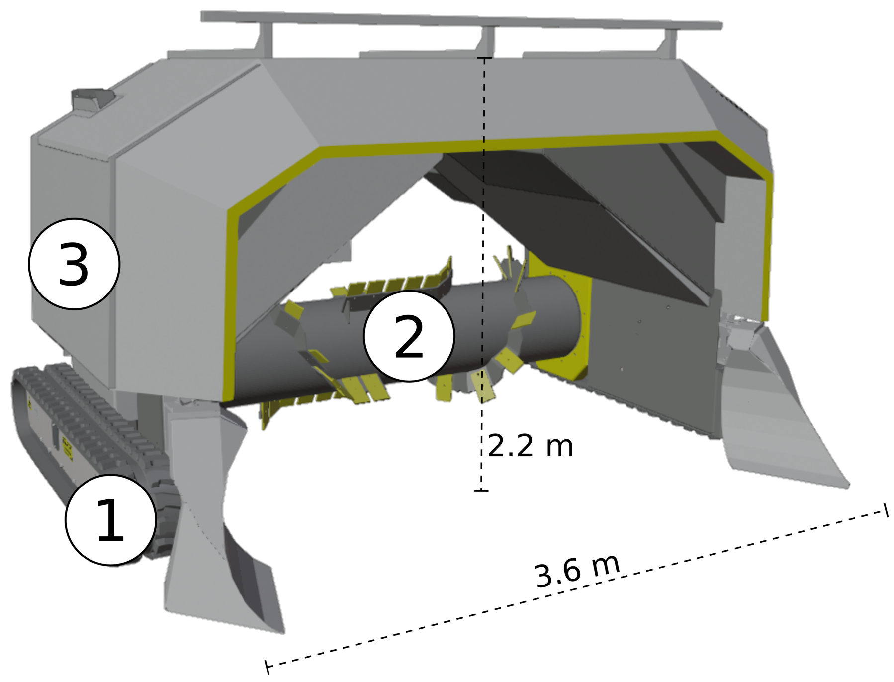
  • We present the development of an electric, self-driving, autonomous compost turner as displayed in Figure 2.
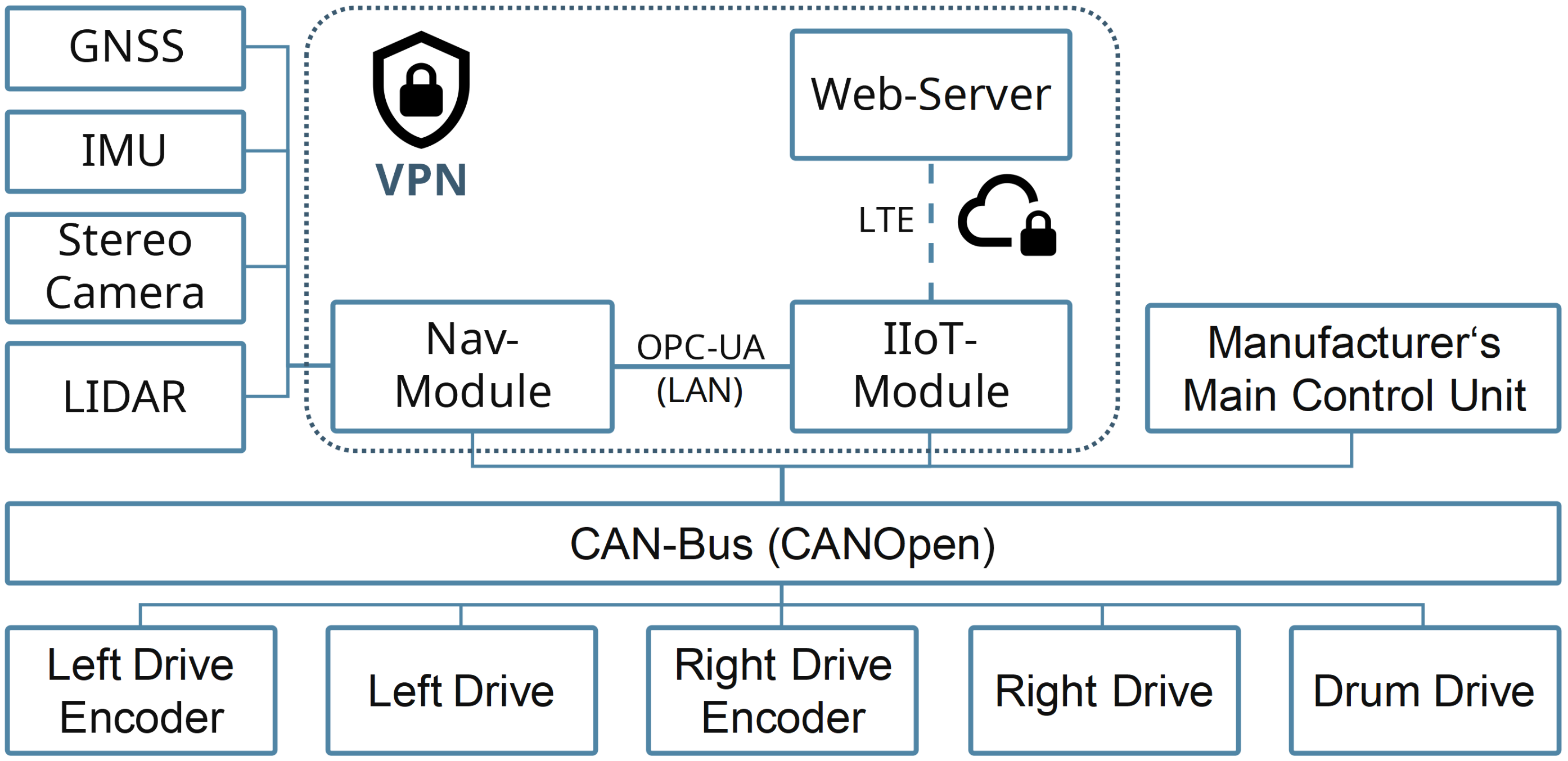
  • We describe aspects of the hardware design, that is, sensor mounting and setup, a navigation module, and an IIoT module for control and data processing tasks. We also present the interfaces and interactions of components on a system-wide level.
  • Furthermore, we describe the architecture of concepts, models, and software integration. In detail, the navigation tasks consisting of navigation filter and sensor fusion, compost windrow detection algorithm and route planning within the compost plant are presented. In addition to the control tasks, we describe the IIoT module’s real-time cloud-based processing tasks of compost data.
  • The proposed concepts are validated by analyzing the performance of the autonomous compost turner in three path-following scenarios.

2. Materials and Methods

The present section addresses the architecture and structure of the required technical design components to achieve the desired degree of automation of the compost turner. Both the hardware and the software architecture are considered. The aim of the section is to provide in the first step an overview of all the elements necessary for the automation, in order to describe detailed aspects in the next step. Thus, the first subsection is focused on the hardware and sensor setup, while the second subsection presents the software architecture.

2.1. Setup of Hardware, Modules and Tools

2.1.1. The Electric Compost Turner

Compost turners are used in commercial composting to regularly turn the compost windrows. For this research, a fully electric compost turner, as can be seen in Figure 3, was used. The machine was developed by our industrial partner. The vehicle is designed for the rough environmental conditions on a composting site and therefore uses two tracks for driving. The vehicle travels at a maximum of 0.5 m per second during compost turning. With a track width of 3.6 m and a height of 2.2 m, the turner can drive through the windrows lengthwise. At the center of the compost turner, the spiked drum is positioned. It picks up the compost material at the front and throws it out at the back of the machine, mixing the compost in the process. The drum has a diameter of 0.55 m and rotates approximately three times per second when driving through a windrow. Especially during the turning process, when the drum is active, the vehicle is subject to strong vibrations, which have to be taken into account for the navigation sensor selection. The control cabinet of the machine is located below the side panel.

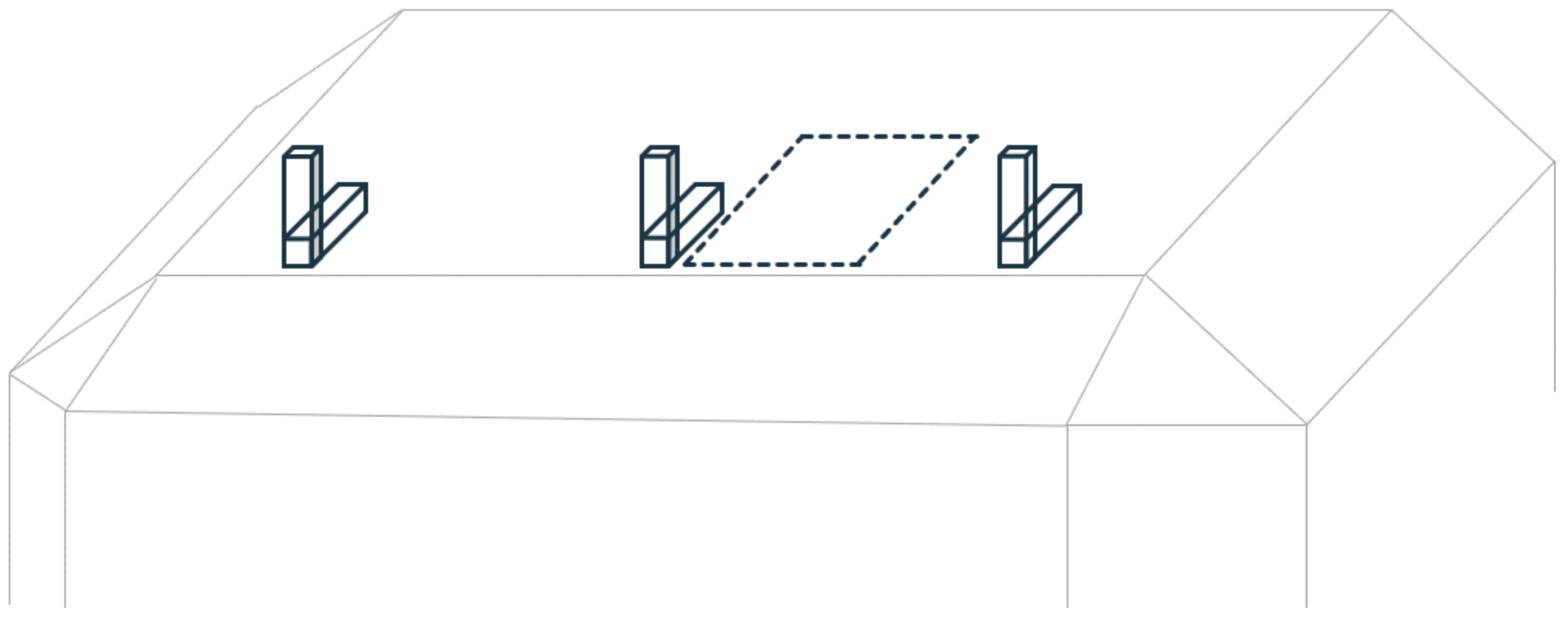
2.1.2. Navigation Sensors

To achieve autonomous driving of the compost turner, a multitude of sensors and actuators were necessary. However, it must be explicitly pointed out that the present work was carried out in the course of a research project with a strong industrial focus. Accordingly, certain sensors, such as the encoders of the drives, were already installed on the compost turner, while other sensors had to be added. Additionally, the compost turner was operating on a daily basis at an industrial composting plant. Therefore, the setup of the sensors, navigation and control modules always had to be performed in such a way that the daily operations of the compost turner on the composting plant would not be disturbed by the research activities in the slightest. As will be discussed in greater detail subsequently, a strong focus was placed on the design of a modular structure during the entire development phase of the hardware setup. This modular design should allow a quick mounting and dismounting of the sensors to reduce the downtime of the compost turner for the plant operators as much as possible. In this context, a brief note must also be made regarding the design of the control system. As already mentioned, the compost turner was used in ongoing operations apart from the research project. Accordingly, the design of the control system did not only have to satisfy the requirements for modularity. Moreover, a guarantee had to be provided that the research project’s control system could be completely switched off at the end of the regular test runs. This reset to the initial state was of the utmost importance to ensure the reliable industrial daily operation of the compost turner. Considering the mentioned aspects, the basic structure of the sensors and the automation modules will be presented in the following. Selection of the navigation sensors was an especially significant aspect; therefore, this issue was addressed over the course of several series of experiments [30,31]. Based on these test series, a sensor setup was developed. While an initial attempt has already been presented in [32], a more mature version shall be presented at this point. In the first step, a dual antenna GNSS receiver with access to network RTK, a mid-range MEMS IMU, and an optical LiDAR sensor were selected. The compost turner used in the experiments had two rotary encoders, which provided the angular velocity of the left and right tracks. In addition, a stereo camera was used for visual feedback but not integrated in the navigation solution. Table 1 shows a summary of the used sensors.
The aforementioned modularity of the sensors was ensured by a mounting frame. The basic idea was to provide an option for quickly and precisely attaching the sensors (and subsequently detaching them again), while minimizing the need to modify the outer surface of the compost turner. In consultation with the industry partner, a two-part aluminum structure was created. The first part of the structure consisted of three L-shaped rails that were attached to the compost turner with screw connections as shown in Figure 4. These L-shaped rails formed the basic framework for the sensor rail and were permanently attached to the compost turner so that they remained in place during daily operation in the composting plant. A dashed line in Figure 4 indicates the area where the navigation module with the processing electronics is attached.
The second part consisted of an aluminum profile to which the sensors were attached. This part was not fixed and could therefore be quickly and reliably attached to the L-rails. As shown in Figure 5, the two GNSS antennas, the IMU, the stereo camera, and the LiDAR were attached to the profile. The inclination of the LiDAR could be adapted via an adjustment platform. This was significant since a purely horizontal mounting of the LiDAR would not provide the possibility of detecting objects standing directly in front of the compost turner. By tilting, the field of view of the LiDAR could be adjusted accordingly.

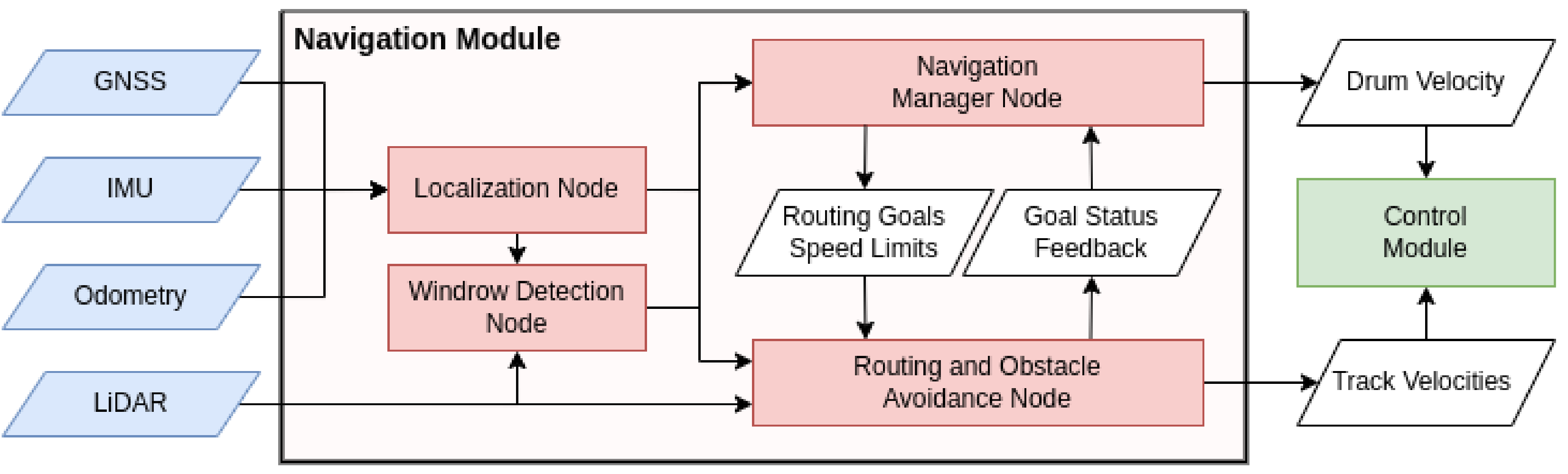
2.1.3. The Navigation Module

For the processing of the sensor data and the subsequent computation of the navigation tasks, a module was designed containing the required evaluation electronics and computational capabilities. As with the sensor rail already presented, it was required that the navigation module could be quickly mounted and dismounted on the compost turner. The module consisted of an Nvidia Jetson Orin as the Embedded Computing Board (ECB), a CAN board, GNSS receiver, power supply and a battery. The Robot Operating System (ROS) version Noetic was installed on the ECB. A detailed execution of the workflows in ROS will take place in the following chapter.

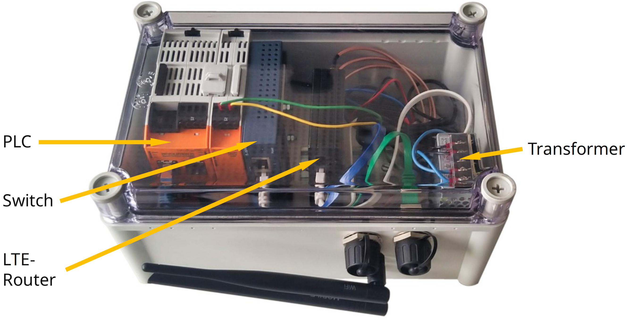
2.1.4. IIoT-Module for Control Tasks and Cloud-Based Data Visualization

An Industrial Internet of Things (IIoT) module was developed for the tasks of controlling the compost turner. In addition, the module should be able to process sensor and navigation data and transmit them encrypted to a web server. At the webserver, the data should be stored in a database and after a post-processing step, a visualization should be performed. Thereby, the key components of the module were a PLC, a switch, an LTE router and a power transformer. While the methodological development of the IIoT module employing a model-based systems engineering approach (MBSE) has already been presented in [33], the integration of the IIoT module into the overall system shall be presented within the current work. Figure 6 provides an illustration of the IIoT module.
The main components of the module were a programmable logic controller (PLC) with a CAN bus adapter, an industrial LTE router, a switch, and a DC-DC voltage transformer. Two dust-proof RJ45 connectors for LAN connections, two SMA connectors for the LTE antennas, and an RP-SMA connector for the Wi-Fi antenna were attached to the outer wall as interfaces. In addition, a female DIN 60130-9 connector was attached, whereby two pins of the connector were used for the power supply (0 V, 24 V), and two pins for the connection to the CAN bus (CAN-High, CAN-Low). A corresponding male counterpart of the DIN connector was installed in the electronic control box of the compost turner. Thus, the IIoT module could be connected via plug-and-play without the need for complicated cabling. The two RJ45 connectors were internally connected to the switch, which were in turn connected to the PLC and the LTE router. As will be described in detail in the following, the RJ45 connectors were mainly required for the communication between the navigation module and the IIoT module within the Robot Operating System (ROS). The RP-SMA and SMA connectors were connected to the LTE router via shielded coaxial cables. A side view of the IIoT module with the described interfaces is shown in Figure 7.

2.2. System Architecture: Hardware Integration on the Industrial Compost Turner

After the sensors, navigation, and IIoT modules presented in detail in the previous section, the aim is now to explore on a system-wide level how these components were integrated into the overall architecture of the industrial compost turner. Figure 8 provides a schematic representation of the relevant components, focusing on the hardware. A more in-depth discussion of the software architecture is given in the subsequent chapter.
The integration of modules and sensors into the existing system of the industrial compost turner is illustrated in Figure 9. The drives of the tracks (Left Drive and Right Drive), their encoders (Right Drive Encoder and Left Drive Encoder), and the drive of the drum (Drum Drive) are permanently integrated in the compost turner and send regular sensor data and status logs to the CAN bus. However, only the Manufacturer’s Main Control Unit is directly allowed to control the drives. Even if it were possible from a technical point of view to control the drives directly via the CAN bus, for example, from the IIoT module, this would involve considerable safety risks. Due to the ongoing operation of the compost turner, it can be assumed that regular maintenance work will take place on the hardware and software. An address conflict on the CAN bus between the manufacturer/maintenance team and the research team must therefore be avoided at all costs. To circumvent this problem, the drive commands were sent in the first place from IIoT Module to the Manufacturer’s Main Control Unit, and subsequently from there to the drives. In this way, the drives only received the drive commands from the Manufacturer’s Main Control Unit. The described setup is shown in Figure 9. All the sensors already presented are connected to the navigation module, which can also read the status and sensor data from the CAN bus. The IIoT module communicates with the manufacturer’s main control unit via the CAN bus and with the navigation module via OPC-UA. Communication with the navigation module via the CAN bus would be technically possible but is less flexible than via the OPC-UA protocol, as will be explained in more detail. The navigation sensors used are connected via manufacturer-specific connections to the navigation module, which also provides their power supply. The navigation module, like the IIoT module, is connected to the internal 24 V power supply of the compost turner. Since the compost turner was in daily industrial use, major parts of the development efforts concerning the functional capabilities of the individual components were shifted to the digital domain. As presented in detail in [34], the modules were tested using hardware-in-the-loop simulations in order to minimize the need for field tests. The web server was also reached via the OPC-UA protocol, with connectivity provided by the IIoT module’s LTE capability mentioned in the previous section. Due to the fact that the compost turner operates in an industrial environment, data security is of the utmost importance. Although the OPC-UA protocol is encrypted by default, an additional layer of security was created by establishing a virtual private network (VPN). At this point, it should be noted that not only could the sensor data be accessed via the LTE connection but the entire compost turner could be controlled via the LTE capability of the IIoT module.

2.3. Architecture of Concepts, Models and Software Integration

The Robot Operating System (ROS) forms the foundation of the software architecture. Of particular advantage was that ROS offers the possibility to split different tasks in small programs, so-called nodes, that communicate using a publisher and subscriber model. These nodes can be written in C++ or Python 3, and a large part of the software development could be conducted exclusively within the ROS framework. Two main subject areas can be defined, as shown in the high-level view in Figure 10. On the one hand, there is the subject area of evaluation and processing the navigation sensor data in order to calculate an optimal trajectory for the compost turner. On the other hand, the second main subject area is the control of the tracks, which receives the calculated target routes as input and sends the control commands to the drives as output. Both topics will be presented in more detail within the following sections.

2.3.1. High-Level View on the Navigation Tasks

Figure 11 depicts the relation of the ROS nodes within the navigation module. The Localization Node takes sensor input and calculates the current robot position, velocity, and attitude in the navigation filter as further described in Section 2.3.2. In the Windrow Detection Node, the current robot pose is used together with the LiDAR sensor output to determine the locations of the windrows in an initialization phase (see Section 2.3.3). The detected windrows can then be selected by a user, and the Navigation Manager Node, which is further described in Section 2.3.5, sends the necessary routing goals and speed limits to the Routing and Obstacle Avoidance Node. The latter node uses LiDAR data for obstacle recognition and outputs the necessary track velocities to follow the calculated route to the control module (see Section 2.3.4). Furthermore, a goal status feedback is sent back to the Navigation Manager Node, where, if a goal has been reached or canceled, the required next action is issued. In addition, based on the current navigation state, the drum velocities are passed on to the control module.

2.3.2. Navigation Filter (Localization Node)

The concept for the navigation filter of the autonomous compost turner was first presented in [30]. The navigation filter is a multi-sensor positioning module, which computes the position, velocity and attitude of the compost turner in real-time.
To fuse data from multiple navigation sensors in real-time, an Error-State Extended Kalman Filter (EKF) was chosen due to its computational efficiency. Two different integration architectures were evaluated [35], a modified federated integration architecture and a cascaded integration architecture. The cascaded integration architecture proved to be more robust for detecting outliers and was therefore used in this research.
As compost turners are subject to strong vibrations, conventional algorithms for GNSS/INS integration fail to properly estimate the position, velocity, and attitude of the compost turner. Therefore, a tailored odometry model for tracked vehicles was developed [36], which allows to bridge GNSS outages. In [37], the model was further extended to properly estimate an odometry bias.
The final multi-sensor positioning module which was used in this study uses a cascaded EKF to fuse data from GNSS, the IMU, and the rotary encoders. Data from GNSS and the IMU are used in the measurement update of the EKF, and data from the rotary encoders with the tailored odometry model are used in the prediction step. With the proposed architecture, a 3D position accuracy of less than 10 cm and a heading accuracy of less than 1° can be achieved [37] in real-time.

2.3.3. Windrow Detection

To allow the compost turner to automatically turn specific windrows, it needs to know where the individual windrows are located at the composting site. Each time new, fresh windrows are piled up or when the windrows are moved after a certain composting stage, the windrow locations must be updated for the routing module to work. This usually happens every few weeks, and during a single composting process the windrows can be assumed stationary. Although it could theoretically be automatized, due to the sparsity of times where new windrow locations are needed, a semi-automatic initialization process was chosen. In this initialization phase, the robot was manually steered along one side of the windrow composting area. Simply put, the LiDAR sensor output was used to generate a 3D point cloud of the environment from which an optimal route through each individual windrow could be derived.
Therefore, each individual, local LiDAR scan was georeferenced using the position and attitude output of the navigation filter from Section 2.3.2. Using knowledge of the windrow composting area and the shape of the windrows [38], the point clouds could be filtered in such a way that only points belonging to windrows remained (see Figure 12). From the combined, global point cloud, the individual windrow point clouds could be extracted using Euclidean cluster detection. The optimal route should follow the ridge of each windrow. Therefore, the ridge points from each windrow cluster were extracted through various steps involving, for example, RANSAC filtering. Finally, the best fitting line was estimated through these points to find the start and end points of the compost windrow. Since the windrows in our scenario were nearly straight, the line fitting was found to be sufficient to obtain coarse start and end points for the windrows. In case the windrows are more curved, a polynomial fitting would be beneficial.

2.3.4. Route Planning

The route planning node can receive routing goals to which the compost turner should move. Its target is to calculate the optimal route from the current robot position to the goal while avoiding obstacles, and to output the necessary linear and angular velocity commands to the control module. Within the ROS framework, the move_base package provides the necessary functionality. This package was adapted and parameterized to be suitable for the compost turner’s size and dynamics. The routing is based on a global and a local path planning algorithm. The global planner is based on the Dijkstra algorithm [39] and calculates a coarse path to the current routing goal with a slow update rate. The local planner is based on the TEB method [40] and calculates a short path that follows the global path. This short path can be updated with a high frequency which makes the local planner essential to avoid obstacles (especially dynamic obstacles). Both planners use two-dimensional cost maps to calculate the path. To each grid cell of a cost map, a cost value is assigned. By assigning obstacles that are detected using the LiDAR scanner, a high cost value, the planner, and therefore the robot, is able to avoid obstacles.

2.3.5. Navigation Manager

The purpose of the navigation manager node is to act as a link between the navigation filter (Section 2.3.2), windrow detection (Section 2.3.3), and route planning node (Section 2.3.4). For functioning autonomous navigation of the compost turner on the composting site, it is a requirement that the machine can approach, turn, and switch between individual windrows. All these maneuvers require a different behavior. Therefore, a state machine was implemented. Currently, seven different states exist:
  • Idle: Basic state at the start and after finishing or canceling the navigation.
  • Initialize: State when the manual initialization phase (see Section 2.3.3) is performed.
  • On Site: State for normal driving on the composting site (e.g., after turning a windrow and moving to the start of the next one). Here, the detected windrow start and end points act as the routing goals, and the obstacle detection is active. The compost turner drives with the standard velocity limits, and the drum speed is zero.
  • Local Correction: State in which deviations of the windrow detection results from the actual start point of the windrow are corrected. The navigation manager switches to this state after the windrow start point is reached. Here, the local LiDAR point cloud is used to detect the ridge of the windrow that is currently in front of the machine. If the across-track deviation of the robot compared to the locally detected windrow is too large, a correction maneuver is performed.
  • Windrow Start: State after the local correction occurred. The compost turner is at the start of the windrow. In this state, the track speed limits are reduced to drive through the windrow slowly, and the drum is started. The obstacle detection is deactivated while moving through the windrow.
  • In Windrow: State for the turning process of the windrow. The drum turns with the maximum allowed speed, and the local LiDAR point cloud is used to keep the compost turner centrally aligned to the windrow.
  • Windrow End: State towards the end of the windrow. Here, the drum is stopped, and after reaching the windrow endpoint, the state is switched back to Idle or On Site, where the track speed limits are set back to normal, and the obstacle detection is set to active.
The navigation manager node switches between the states accordingly. It also includes a simple Graphical User Interface (GUI) to provide an interaction possibility and information output to the user. Through the GUI, the manual initialization phase (see Section 2.3.3) can be started, and after the windrows are detected, the user can select which windrows the compost turner should turn. Also, specific goals like, for example, a charging station can be selected. Based on the user selection, a list of routing goals (waypoints) is generated by the navigation manager, and the goals are passed on to the route planning node one after another. That way, the compost turner is able to automatically turn the windrows that are selected. A conceptual image of this selection and planning process is shown in Figure 1.

2.3.6. Control Tasks of the IIoT Module

The IIoT module was methodically designed using a model-based systems engineering approach and includes two sub-modules. The former was responsible for control tasks of the compost turner’s tracks and will be discussed in the present section. The following section will deal with the latter subsystem, which was responsible for the acquisition, processing, transmission to the web server, and visualization of the compost data. The ROS framework offers numerous packages which can be freely accessed and adapted. Besides the obvious advantages of open-source packages, however, increased attention must be paid to the reliability of the software implementation. Due to the industrial environment in which the compost turner operates, a robust control of the tracks was of major importance. The mentioned robustness does not only refer to the theoretical control error, that is, the deviation from the target trajectory. In particular, the software implementation had to meet industrial standards since, due to the high drive power of the compost turner, a false control command would have severe consequences.
Thus, we employed an industrial-proven differential drive control leveraging ROS-industrial. Thereby, ROS-industrial is an international open-source project that promotes the use of ROS in the industrial environment of robotics and manufacturing automation. One of the ROS packages for control applications funded in this framework is ros_control [41]. The package provides pre-defined interfaces for the controller, controller manager and hardware interfaces. Due to its broad applicability, the package is used in many areas of research and industry.
A sub-package of ros_control provides a differential drive controller. In contrast to other forms of control approaches, such as the model predictive control, the differential drive controller is less complex but offers the advantage that only algebraic equations must be solved instead of differential equations. This leads to a significantly lower computing time, which in turn contributes to the stability of the entire ROS framework. Since it is not within the scope of the present work, a more in-depth discussion of alternative control approaches and respective tools can be found in [42,43,44]. As already mentioned, the implementation of the open-source package ros_control, which has already been tested in an industrial environment, as well as the existing integration in the ROS framework, were decisive for the choice of the differential drive controller.
From a mathematical perspective, the differential drive controller can be easily formulated by deriving the inverse kinematics of the differential drive robot’s equation of motion:
ω R = V + ω · b / 2 r , ω L = V ω · b / 2 r
A representation of the robot’s equation of motion is shown in Figure 13. Thereby, V is the linear velocity in the direction of travel, denoted as lin_vel in ROS. ω is the steering input, denoted as ang_vel in ROS. Furthermore, the width of the vehicle b and the radius r are given. In the specific case, the radius corresponds to the radius of the tracks of the compost turner. ω R and ω L are the angular velocities of the right and left wheel, that is, in the present case, the angular velocity of the tracks.
The diff drive controller’s input, that is, the linear and angular velocity, are constrained by a maximum velocity, as well as minimum and maximum acceleration. This is significant because, even if the controller misbehaves, like, for instance, a discontinuous jump as control input, this drive command is first smoothed over the constraints before it is passed on to the real machine.
A high-level overview of the control workflow is shown in Figure 14. The starting point is the command velocity calculated in the navigation task, consisting of the linear component v and the angular component omega. The diff_drive_controller is loaded into a controller manager, and a configuration of the parameter set is performed in advance, such as defining the velocity and acceleration constraints. The control output is obtained by accessing the ROS hardware_interface. It is worth noting that the underlying idea of the hardware_interface would be to send the control output directly to the drives of the robot. However, due to the demands on robustness, a different approach was chosen for this project. Specifically, the control outputs were published to a communication node, which forwarded them via Ethernet to a programmable logic controller (PLC) using the OPC-UA protocol. The PLC received the transmitted data and performed a further error analysis. The limits already set with regard to the maximum speed of the drives were verified again and limited in the event of non-compliance. The hardware and software environment of the PLC, which is considered to be particularly reliable, could thus catch potential errors stemming from the Robot Operating System. In the final step, the commands were sent to the compost turner manufacturer’s controller, which forwarded the commands to the drives. This last step in the workflow was necessary, as only the compost turner’s manufacturer has direct access to the drives.

2.3.7. Cloud-Based Data Processing Tasks of the IIoT Module
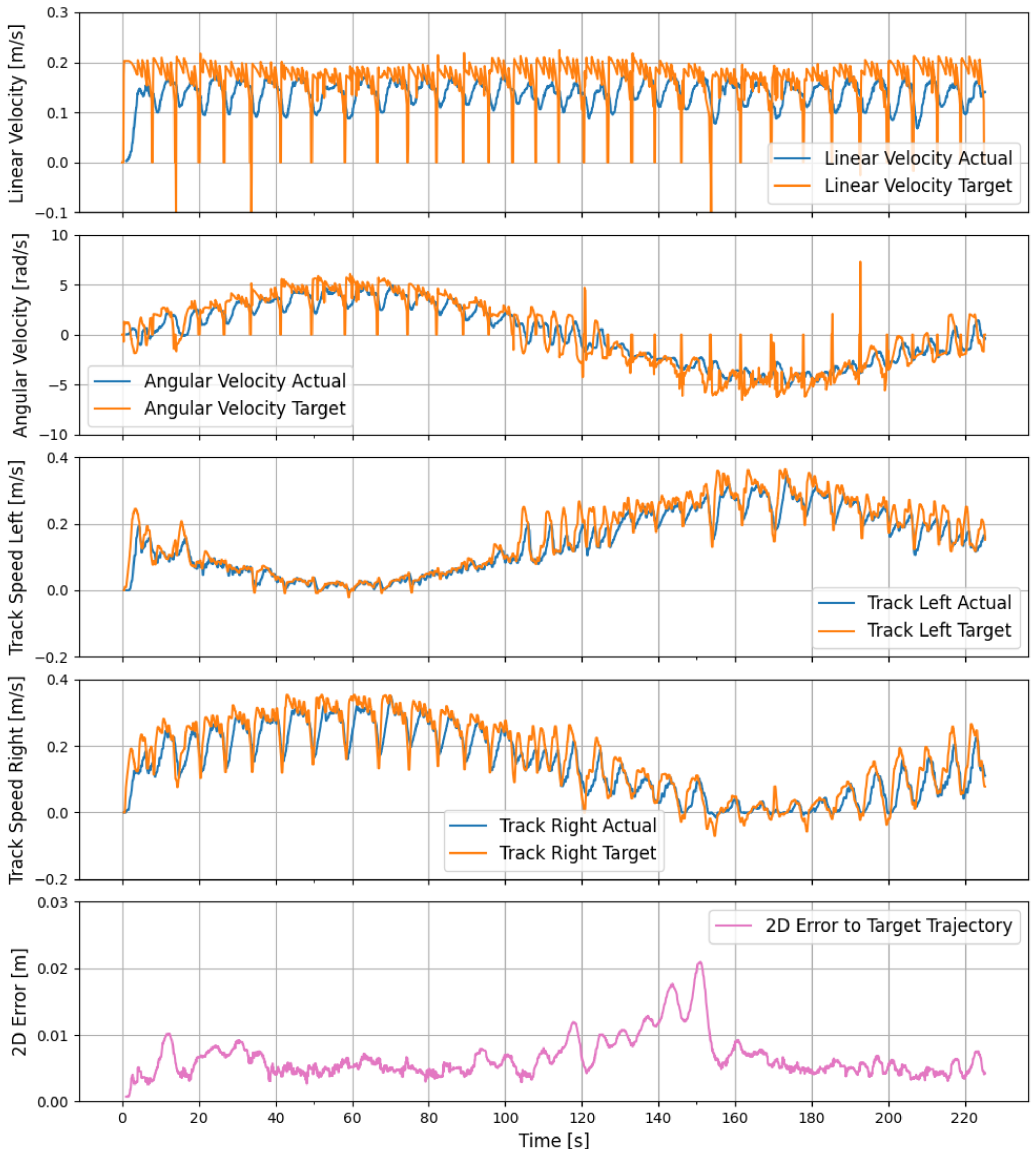
The underlying idea of the cloud-based data processing task of the IIoT module is that composting data should be made available to the plant operator in real-time. Of particular significance are the concentrations of carbon dioxide (CO 2 ) and methane (CH 4 ), as well as the core temperature of the compost windrows. These data shall be automatically processed and prepared, and then transferred to a web server. At the web server, post-processing is performed, the data are stored in a database and visualized on a web frontend. These tasks were methodically addressed in a model-based systems engineering approach; the detailed results have already been presented in [33]. Therefore, a high-level workflow is now presented as Figure 15 displays. Starting from the sensors, which are connected to the CAN bus via the CANopen protocol, the data are sent to the navigation module in the first step. At this point, an initial pre-processing of the data takes place. The idea is to assign a georeference (geotag) and a time stamp (time tag) to the gas and temperature data. Thus, a visualization of all heaps at the compost plant can be displayed afterward on the web interface, and the methane content and temperature can be displayed. Utilizing the OPC-UA connection to the IIoT module, the data are forwarded after the pre-processing step. In the IIoT module, the data are compressed and sent to a web server using the module’s LTE capability. The transmission takes place encrypted via the VPN. At the web server, the compost data are stored in a database and displayed visually in a frontend after post-processing. Regarding the visualization, it should be noted that the operator requires a visualization of the compost data over a period of several months, while daily fluctuations do not contribute significant information concerning the quality of the compost.

3. Results

The preceding methods section covered the design and architecture of aspects of the hardware, starting from the selection of sensors up to the high-level view of sensors, navigation, and control modules. Equally, the employed mathematical methods, models and algorithms and the resulting system architectures have been presented. The aim of the present section is to demonstrate that the resulting overall system of the autonomous compost turner meets the required expectations as outlined in the introduction chapter. A great variation of different mobile robots are used in the relevant literature, with their exact parameters (width, length, and weight) often varying. However, the basic physical properties always remain the same. From a scientific perspective, it is therefore justifiable to transfer the driving scenarios frequently found in the literature to the present study. To demonstrate the capability of the autonomous compost turner, three clearly defined experimental scenarios will be presented. The setup of the scenarios is strongly based on standard procedures as commonly found in the respective scientific literature. In the first scenario, the ability of the compost turner to follow a curve with a pre-defined radius as accurately as possible is examined. The specified curve is, therefore, a circle, and a comparison is performed between the target trajectory and the actual trajectory [45]. The second scenario is an extension of the first one. The driving command of the vehicle under test is a continuously changing steering input, and the pre-defined target trajectory is a Bernoulli lemniscate in the form of an infinity shape [46]. To be consistent with domain-specific literature, an application-specific capability of the autonomous vehicle will be demonstrated in the third scenario [47,48,49]. In the specific case, driving towards a windrow, precision adjustment and alignment in front of the windrow, and the subsequent turning of the compost windrow will be demonstrated. In all three scenarios, the compost turner followed the target trajectory using waypoints as routing goals that were passed on to the routing algorithm. The compost turner setup and environmental conditions remained the same throughout the experiment. The sensors, navigation and control modules were configured according to the specifications provided in Section 2, the methods section. The experiments were conducted on a concrete surface covered with a layer of dust and composting residues as would normally be found in an industrial composting plant. The weather conditions were clear, and the ground surface was dry.

3.1. Scenario 1: Validation of the Waypoint Navigation—Following a Circle

In the first test scenario, the given trajectory is a circle, which is driven by the compost turner counterclockwise with a steering angle to the left. In total, 32 waypoints or routing goals are distributed around the circle. Due to the simple shape of the trajectory, a validation of the waypoint navigation can be carried out easily. The results are shown in Figure 16 and Figure 17. As is visible in the illustrations, there are only minor deviations of around one centimeter between the target trajectory and the actual trajectory. It can be said that the compost turner can follow the target trajectory without difficulty. The results of this scenario are consistent with the findings of similar studies published in the literature. For example, authors of [46] obtained comparable results, although a much smaller robot platform with a length of about 50 cm and a weight of about 10 kg was used. The waypoint following is clearly evident in the velocity plots of the tracks in Figure 17. The autonomous compost turner always heads towards a target goal on the circle, and as soon as it reaches the goal, it moves on to the next target goal, resulting in an apparent oscillatory behavior. In practice, when turning windrows for example, this oscillating behavior is no disadvantage because the waypoints are further apart.

3.2. Scenario 2: Bernoulli Lemniscate—Infinity Shape

The given trajectory in the second scenario is a Bernoulli lemniscate, which is defined by the following equations and results in an infinity-shaped curve. In the equations, a represents the radius of the shape, and the angle t runs from 0 to 2 π :
x = a · cos ( t ) 1 + sin 2 ( t ) , y = a · sin ( t ) · cos ( t ) 1 + sin 2 ( t )
Figure 18 presents the results of the second scenario. As in the first scenario, the first figure shows the actual trajectory and the target trajectory goals in a 2D plot, whereas the second figure shows the actual and target velocities of the robot and the tracks as well as the 2D error between the actual and the target trajectory. In Scenario 2, the target trajectory is also divided into tightly spaced discrete target goals, to which the compost turner drives in sequence. As a result, the apparent oscillatory behavior can also be seen in Figure 19, which, however, only results from the successive approach of the target goals. As can be seen in Figure 19, Scenario 2 also demonstrates that the trajectory of the infinity shape can be followed without any major deviations. Thus, the results of this scenario also agree with the existing literature as presented in [46]. The findings presented within this work even indicate a slightly better performance in terms of minimizing the 2D error, as shown in Figure 19.

3.3. Scenario 3: Turning a Windrow

Scenario 3 demonstrates the main task of the compost turner, which is the autonomous turning of compost windrows. Figure 20 shows the compost turner’s trajectory driving towards and through a windrow at the composting plant. The compost turner is first located on a path at the composting plant. When a command to turn a specific windrow is issued by the operator, the compost turner moves towards the specified windrow. A more close-up view is shown in Figure 21, where the local approach maneuver that the compost turner performs to be centrally aligned with the compost windrow can be seen. This maneuver is necessary if the windrow start point determined by the windrow detection algorithm has some deviation from the actual starting point of the windrow. Such a deviation can occur if the actual windrow is slightly curved and therefore not perfectly representable by a straight line.
Figure 22 shows that once the compost turner has reached the start of the compost windrow, the drum is started, and the maximum speed is decreased. During the turning process, the compost turner attempts to follow the navigation targets in the compost windrow and sends respective heading adjustment commands to the left and right tracks. Those corrections are visible as oscillatory behavior in Figure 22. Once the end of the compost windrow is reached, the drum velocity is slowed down, and the maximum speed limits are changed back to normal. The compost turner can now move to another compost windrow if this was requested by the operator.

4. Conclusions and Outlook

This paper presented the development of a self-driving autonomous compost turner. First, the hardware design was described. The machine was equipped with sensors for navigation, as well as an IIoT-module for control tasks and a link to a web server. A special focus was put on the modular design of the hardware setup, i.e., a sensor rail that allows for quick mounting and dismounting was developed.
Then, the software and the functionality of the autonomous compost turner were presented. The software architecture was developed using ROS. The navigation module uses an EKF which fuses data from GNSS, an IMU, and the rotary encoders to estimate the current position and orientation of the autonomous compost turner. The highly accurate position of the machine and the LiDAR data were used to create a 3D point cloud of the composting site. A tailored windrow detection algorithm was developed to estimate the optimal route for the compost turner through the windrows from the 3D point cloud. To compute the optimal routes towards the windrows, the move_base package by ROS was adapted. Additionally, a state machine was implemented for the different navigation states of the autonomous compost turner (e.g., local approach to the windrow, starting to turn the windrow, and turning the windrow). To steer the compost turner along the computed optimal routes, a differential drive controller of the ros_control package was used. For additional security, the output of the differential drive controller was sent to a PLC for further checks and error analysis before the steering commands were sent to the main control.
To evaluate the overall concept of the autonomous compost turner, three test scenarios were presented. In the first two scenarios, the compost turner was set to follow pre-defined shapes, a circle and an infinity shape. In both scenarios, the compost turner was able to follow the pre-defined shapes with a 2D error of less than 2.5 cm. The third scenario was application specific to show the full functionality of the autonomous compost turner. The machine, which was located at the composting site, was given a command to steer a specific windrow. This allowed to test all phases of the state machine, such as the navigation on the composting site, locally approaching a windrow, starting to turn a windrow, turning a windrow, stopping to turn the windrow, and switching back to idle to wait for the next command. The compost turner successfully managed to navigate through all these phases autonomously. This shows that the proposed system design is suitable for an autonomous compost turner.
The current paper addressed the development of a single autonomous compost turner. In the future, a collaborative approach of several autonomous vehicles at the composting site will be investigated to further automate the composting process [50]. Moreover, a focus will be put on sharing concepts for autonomous compost turners [51,52,53]. A sharing model would allow for more composting sites to have access to the autonomous compost turner. This would further help to reduce the need for manual labor at composting sites. Moreover, as autonomous compost turners allow for slow, layer-by-layer turning of the compost, more high-quality compost can be produced, and a positive contribution can be made towards the EU goals for a circular and sustainable economy.

Author Contributions

Conceptualization, M.C., E.B., F.T. and C.S.; methodology, M.C., E.B., F.T. and C.S.; software, M.C., E.B., F.T. and C.S.; validation, M.C., E.B., F.T. and C.S.; investigation, M.C., E.B., F.T. and C.S.; resources, M.C., E.B., F.T. and C.S.; data curation, M.C., E.B., F.T. and C.S.; writing—original draft preparation, M.C., E.B., F.T. and C.S.; writing—review and editing, M.C., E.B., F.T. and C.S.; visualization, M.C., E.B., F.T. and C.S.; supervision, M.C.; project administration, M.C.; funding acquisition, M.C., E.B., F.T. and C.S. All authors have read and agreed to the published version of the manuscript.

Funding

This research was funded by the TU Graz Open Access Publishing Fund and the Austrian Federal Ministry of Finance via the Austrian Research Promotion Agency in the research project ANDREA (Grant No. 885368). The project used open-source software funded by the European Union’s Horizon 2020 research and innovation program under grant agreement No. 732287.

Institutional Review Board Statement

Not applicable.

Informed Consent Statement

Not applicable.

Data Availability Statement

Data available on request from the authors.

Acknowledgments

The authors would like to thank their project partners at Sonnenerde GmbH, Pusch & Schinnerl GmbH, and the Institute of Logistics and Material Handling Systems at the Otto von Guericke University Magdeburg.

Conflicts of Interest

The authors declare no conflicts of interest.

References

  1. Commission, E. Circular Economy Action Plan—For a Cleaner and More Competitive Europe; Publications Office of the European Union: Luxembourg, 2020. [Google Scholar]
  2. Sulewski, P.; Kais, K.; Gołaś, M.; Rawa, G.; Urbańska, K.; Wąs, A. Home Bio-Waste Composting for the Circular Economy. Energies 2021, 14, 6164. [Google Scholar] [CrossRef]
  3. Adhikari, B.K.; Barrington, S.; Martinez, J.; King, S. Characterization of Food Waste and Bulking Agents for Composting. Waste Manag. 2008, 28, 795–804. [Google Scholar] [CrossRef] [PubMed]
  4. Dunst, G. Kompostierung und Erdenherstellung: Praxisbuch und Anleitung für Hausgarten, Landwirtschaft, Kommune und Profi, 1st ed.; Sonnenerde: Riedlingsdorf, Austria, 2015. [Google Scholar]
  5. Razza, F.; D’Avino, L.; L’Abate, G.; Lazzeri, L. The Role of Compost in Bio-waste Management and Circular Economy. In Designing Sustainable Technologies, Products and Policies: From Science to Innovation; Benetto, E., Gericke, K., Guiton, M., Eds.; Springer International Publishing: Cham, Switzerland, 2018; pp. 133–143. [Google Scholar] [CrossRef]
  6. Sweeten, J.M. Composting Manure and Sludge; Texas A&M AgriLife Extension: College Station, TX, USA, 2008; Available online: https://hdl.handle.net/1969.1/87650 (accessed on 21 July 2024).
  7. Van Der Linden, A.; Reichel, A. Bio-Waste in Europe: Turning Challenges into Opportunities; Publications Office of the European Union: Luxembourg, 2020. [Google Scholar] [CrossRef]
  8. Kuhlman, L.R. Windrow Composting of Agricultural and Municipal Wastes. Resour. Conserv. Recycl. 1990, 4, 151–160. [Google Scholar] [CrossRef]
  9. Moysiadis, V.; Sarigiannidis, P.; Vitsas, V.; Khelifi, A. Smart Farming in Europe. Comput. Sci. Rev. 2021, 39, 100345. [Google Scholar] [CrossRef]
  10. Kawasaki, H.; Murakami, S.; Kachi, H.; Ueki, S. Novel Climbing Method of Pruning Robot. In Proceedings of the 2008 SICE Annual Conference, Chofu, Japan, 20–22 August 2008; pp. 160–163. [Google Scholar] [CrossRef]
  11. Ishigure, Y.; Hirai, K.; Kawasaki, H. A Pruning Robot with a Power-Saving Chainsaw Drive. In Proceedings of the 2013 IEEE International Conference on Mechatronics and Automation, Takamatsu, Japan, 4–7 August 2013; pp. 1223–1228. [Google Scholar] [CrossRef]
  12. Adamides, G.; Katsanos, C.; Parmet, Y.; Christou, G.; Xenos, M.; Hadzilacos, T.; Edan, Y. HRI Usability Evaluation of Interaction Modes for a Teleoperated Agricultural Robotic Sprayer. Appl. Ergon. 2017, 62, 237–246. [Google Scholar] [CrossRef] [PubMed]
  13. Oberti, R.; Marchi, M.; Tirelli, P.; Calcante, A.; Iriti, M.; Tona, E.; Hočevar, M.; Baur, J.; Pfaff, J.; Schütz, C.; et al. Selective Spraying of Grapevines for Disease Control Using a Modular Agricultural Robot. Biosyst. Eng. 2016, 146, 203–215. [Google Scholar] [CrossRef]
  14. Gonzalez-de Soto, M.; Emmi, L.; Perez-Ruiz, M.; Aguera, J.; Gonzalez-de Santos, P. Autonomous Systems for Precise Spraying – Evaluation of a Robotised Patch Sprayer. Biosyst. Eng. 2016, 146, 165–182. [Google Scholar] [CrossRef]
  15. Comba, L.; Gay, P.; Ricauda Aimonino, D. Robot Ensembles for Grafting Herbaceous Crops. Biosyst. Eng. 2016, 146, 227–239. [Google Scholar] [CrossRef]
  16. Bloch, V.; Degani, A.; Bechar, A. A Methodology of Orchard Architecture Design for an Optimal Harvesting Robot. Biosyst. Eng. 2018, 166, 126–137. [Google Scholar] [CrossRef]
  17. Eizicovits, D.; Tuijl, B.; Berman, S.; Edan, Y. Integration of Perception Capabilities in Gripper Design Using Graspability Maps. Biosyst. Eng. 2016, 146, 98–113. [Google Scholar] [CrossRef]
  18. Barth, R.; Hemming, J.; Henten, E.J. Design of an Eye-in-Hand Sensing and Servo Control Framework for Harvesting Robotics in Dense Vegetation. Biosyst. Eng. 2016, 146, 71–84. [Google Scholar] [CrossRef]
  19. Kurtser, P.; Edan, Y. Statistical Models for Fruit Detectability: Spatial and Temporal Analyses of Sweet Peppers. Biosyst. Eng. 2018, 171, 272–289. [Google Scholar] [CrossRef]
  20. Longo, D.; Muscato, G. Design and Simulation of Two Robotic Systems for Automatic Artichoke Harvesting. Robotics 2013, 2, 217–230. [Google Scholar] [CrossRef]
  21. AGCO GmbH. Project Xaver. 2024. Available online: https://www.fendt.com/de/2-fendt-xaver (accessed on 21 July 2024).
  22. Naio Technologies. 2024. Available online: www.naio-technologies.com (accessed on 21 July 2024).
  23. FarmDroid. 2024. Available online: www.farmdroid.dk (accessed on 21 July 2024).
  24. Shamshiri, R.R.; Weltzien, C.; Hameed, I.A.; Yule, I.J.; Grift, T.E.; Balasundram, S.K.; Pitonakova, L.; Ahmad, D.; Chowdhary, G. Research and Development in Agricultural Robotics: A Perspective of Digital Farming. Int. J. Agric. Biol. Eng. 2018, 11, 1–14. [Google Scholar] [CrossRef]
  25. Bac, C.W.; Roorda, T.; Reshef, R.; Berman, S.; Hemming, J.; van Henten, E.J. Analysis of a Motion Planning Problem for Sweet-Pepper Harvesting in a Dense Obstacle Environment. Biosyst. Eng. 2016, 146, 85–97. [Google Scholar] [CrossRef]
  26. Hameed, I.; Cour Harbo, A.; Osen, O. Side-to-Side 3D Coverage Path Planning Approach for Agricultural Robots to Minimize Skip/Overlap Areas between Swaths. Robot. Auton. Syst. 2016, 76, 36–45. [Google Scholar] [CrossRef]
  27. Barth, R. Vision Principles for Harvest Robotics: Sowing Artificial Intelligence in Agriculture. Ph.D. Thesis, Wageningen University, Wageningen, The Netherlands, 30 October 2018. [Google Scholar] [CrossRef]
  28. Pierzchała, M.; Giguère, P.; Astrup, R. Mapping Forests Using an Unmanned Ground Vehicle with 3D LiDAR and Graph-SLAM. Comput. Electron. Agric. 2018, 145, 217–225. [Google Scholar] [CrossRef]
  29. Das, J.; Cross, G.; Qu, C.; Makineni, A.; Tokekar, P.; Mulgaonkar, Y. Devices, Systems, and Methods for Automated Monitoring Enabling Precision Agriculture. In Proceedings of the 2015 IEEE International Conference on Automation Science and Engineering (CASE), Gothenburg, Sweden, 24–28 August 2015. [Google Scholar] [CrossRef]
  30. Reitbauer, E.; Schmied, C.; Wieser, M. Autonomous Navigation Module for Tracked Compost Turners. In Proceedings of the 2020 European Navigation Conference (ENC), Dresden, Germany, 23–24 November 2020; p. 10. [Google Scholar] [CrossRef]
  31. Reitbauer, E.; Schmied, C.; Schedler, M. Integrated Navigation for Tracked Compost Turners Using GNSS, INS, Odometers, Stereo Camera and 3D Map. In Proceedings of the 33rd International Technical Meeting of the Satellite Division of the Institute of Navigation (ION GNSS+ 2020), Online, 21–25 September 2020. [Google Scholar] [CrossRef]
  32. Cichocki, M.; Reitbauer, E.; Theurl, F.; Schmied, C. Composting 4.0: From The Automatic Steering Of Compost Turners Towards An Autonomous Plant Management. In Proceedings of the 7th Central European Biomass Conference CEBC 2023, Graz, Austria, 18–20 January 2023. [Google Scholar] [CrossRef]
  33. Cichocki, M.; Landschützer, C. Leveraging Advanced Technologies in Industrial Composting Plants: Exploring Technical and Logistical Opportunities to Achieve Industry 4.0 Standards. Logist. J. 2023. [Google Scholar] [CrossRef]
  34. Cichocki, M.; Reitbauer, E.; Schmied, C.; Theurl, F. From Waste to Resource: Leveraging Simulation-based Technologies in the Development of an Autonomous Compost Turner. In Proceedings of the Logistikwerkstatt Graz, Graz, Austria, 8–9 May 2023. [Google Scholar] [CrossRef]
  35. Reitbauer, E.; Schmied, C. Performance Analysis of GNSS/INS/VO/Odometry Sensor Fusion Algorithms for Tracked Agricultural Vehicles. In Proceedings of the 34th International Technical Meeting of the Satellite Division of the Institute of Navigation (ION GNSS+ 2021), St. Louis, MO, USA, 20–24 September 2021; p. 3262. [Google Scholar] [CrossRef]
  36. Reitbauer, E.; Schmied, C. Bridging GNSS Outages with IMU and Odometry: A Case Study for Agricultural Vehicles. Sensors 2021, 21, 4467. [Google Scholar] [CrossRef] [PubMed]
  37. Reitbauer, E. Multi-Sensor Positioning for the Automatic Steering of Tracked Agricultural Vehicles. Verlag der Technischen Universität Graz: Graz, Austria, 2022; ISBN 978-3-85125-919-3. [Google Scholar] [CrossRef]
  38. Theurl, F.; Schmied, C.; Reitbauer, E.; Wieser, M. Automated Route Planning from LiDAR Point Clouds for Agricultural Applications. Eng. Proc. 2023, 54, 54. [Google Scholar] [CrossRef]
  39. Dijkstra, E.W. A note on two problems in connexion with graphs. Numer. Math. 1959, 1, 269–271. [Google Scholar] [CrossRef]
  40. Roesmann, C.; Feiten, W.; Woesch, T.; Hoffmann, F.; Bertram, T. Trajectory modification considering dynamic constraints of autonomous robots. In Proceedings of the ROBOTIK 2012—7th German Conference on Robotics, Munich, Germany, 21–22 May 2012; pp. 1–6. [Google Scholar]
  41. Chitta, S.; Marder-Eppstein, E.; Meeussen, W.; Pradeep, V.; Tsouroukdissian, A.; Bohren, J.; Coleman, D.; Magyar, B.; Raiola, G.; Lüdtke, M.; et al. Ros_control: A Generic and Simple Control Framework for ROS. J. Open Source Softw. 2017, 2, 456. [Google Scholar] [CrossRef]
  42. Camacho, E.F. Model Predictive Control, 2nd ed.; Advanced Textbooks in Control and Signal Processing; Springer: Berlin/Heidelberg, Germany, 2007. [Google Scholar]
  43. Fiedler, F.; Karg, B.; Lüken, L.; Brandner, D.; Heinlein, M.; Brabender, F.; Lucia, S. do-mpc: Towards FAIR nonlinear and robust model predictive control. Control Eng. Pract. 2023, 140, 105676. [Google Scholar] [CrossRef]
  44. Cichocki, M. Transforming the Composting Industry towards Industry 4.0 and Physical Internet Capabilities. Doctoral Thesis, Graz University of Technology, Graz, Austria, 2024. [Google Scholar] [CrossRef]
  45. Özdemir, M.N.; Kılıç, V.; Ünlüsoy, Y.S. Transient Tracked Vehicle Steering Model. In Proceedings of the ISTVS 8th Americas Regional Conference, Detroit, MI, USA, 12–14 September 2016; p. 20. [Google Scholar]
  46. Sabiha, A.D.; Kamel, M.A.; Said, E.; Hussein, W.M. ROS-based Trajectory Tracking Control for Autonomous Tracked Vehicle Using Optimized Backstepping and Sliding Mode Control. Robot. Auton. Syst. 2022, 152, 104058. [Google Scholar] [CrossRef]
  47. Endo, D.; Okada, Y.; Nagatani, K.; Yoshida, K. Path Following Control for Tracked Vehicles Based on Slip-Compensating Odometry. In Proceedings of the 2007 IEEE/RSJ International Conference on Intelligent Robots and Systems, San Diego, CA, USA, 29 October–2 November 2007; pp. 2871–2876. [Google Scholar] [CrossRef]
  48. Moosavian, S.; Kalantari, A. Experimental Slip Estimation for Exact Kinematics Modeling and Control of a Tracked Mobile Robot. In Proceedings of the 2008 IEEE/RSJ International Conference on Intelligent Robots and Systems, Nice, France, 22–26 September 2008; pp. 95–100. [Google Scholar] [CrossRef]
  49. Lepej, P.; Maurer, J.; Uran, S.; Steinbauer, G. Dynamic Arc Fitting Path Follower for Skid-Steered Mobile Robots. Int. J. Adv. Robot. Syst. 2015, 12, 139. [Google Scholar] [CrossRef]
  50. CONCLUSION—CO2 Reduction on Industrial Composting Plants Using GNSS-based Cooperative Localization. Available online: https://projekte.ffg.at/projekt/4711800 (accessed on 21 July 2024).
  51. Cichocki, M.; Landschützer, C.; Hick, H. Development of a Sharing Concept for Industrial Compost Turners Using Model-Based Systems Engineering, under Consideration of Technical and Logistical Aspects. Sustainability 2022, 14, 10694. [Google Scholar] [CrossRef]
  52. Cichocki, M.; Landschützer, C.; Barenji, A.V.; Montreuil, B. Physical Internet Based Hyperconnected Logistics Platform Enabling Heavy-Duty Machinery Sharing in the Composting Industry: A Simulation-Based Scenario Investigation. In Proceedings of the 9th International Physical Internet Conference (IPIC 2023), Athens, Greece, 13–15 June 2023. [Google Scholar]
  53. Cichocki, M.; Barenji, A.V.; Montreuil, B.; Landschützer, C. Hyperconnected Logistic Platform for Heavy-Duty Machinery: Leveraging Physical Internet Principles to Drive the Composting Industry. Sustainability 2023, 15, 12898. [Google Scholar] [CrossRef]
Figure 1. Route planning concept.
Sustainability 16 06347 g001
Figure 2. The developed prototype autonomous compost turner while turning a windrow on an industrial composting plant.
Sustainability 16 06347 g002
Figure 3. The compost turner with tracks (1), drum (2), and location of the control cabinet (3).
Sustainability 16 06347 g003
Figure 4. The L-shaped rails are permanently attached to the compost turner and form the basic framework for the sensor rail. The dashed line shows the area where the navigation module, which contains the processing electronics, is attached.
Sustainability 16 06347 g004
Figure 5. The sensors were attached to an aluminum profile, which could be quickly and reliably attached to the L-rails on the compost turner. The degree of inclination of the LiDAR sensor could be variably adjusted as required.
Sustainability 16 06347 g005
Figure 6. The IIoT module is responsible for the control tasks of the compost turner, as well as for the transmission of sensor and navigation data to a web server. The IIoT module consisted of the main components PLC, switch, LTE router, and power transformer.
Sustainability 16 06347 g006
Figure 7. The IIoT module has two dustproof RJ45 interfaces for communication with the navigation module within the Robot Operating System (ROS). The power supply and CAN bus connection is provided via female DIN 60130-9 connectors. Wi-Fi and LTE are enabled via corresponding SMA and RP-SMA interfaces.
Sustainability 16 06347 g007
Figure 8. High-level view of the modules, sensors, and actuators within the system of the autonomous compost turner.
Sustainability 16 06347 g008
Figure 9. Integration of the IIoT module into the circuit box of the autonomous compost turner. The module is designed for plug-and-play use: once the cables are connected, all protocols automatically boot up and subsequently enter operational mode.
Sustainability 16 06347 g009
Figure 10. High-level view of the software architecture. The two main tasks are the navigation and control of the machine.
Sustainability 16 06347 g010
Figure 11. Program flow for the navigation tasks. The sensors are displayed in blue and pass on their data to the subscribing ROS nodes (red) that perform a certain task within the navigation module. The final output of the navigation module is the control commands that are passed on to the control module (green).
Sustainability 16 06347 g011
Figure 12. Process of the windrow detection algorithm for a windrow in a simulation environment. (A) Windrow in simulation environment. (B) Detected windrow points (cyan) after initialization phase. (C) Windrow points after outlier elimination. (D) Ridge points of the windrow. (E) Estimated line through the ridge points [38].
Sustainability 16 06347 g012
Figure 13. Schematic representation of a differential drive robot.
Sustainability 16 06347 g013
Figure 14. Software setup in ROS, PLC, and the manufacturer’s main control unit.
Sustainability 16 06347 g014
Figure 15. A high-level overview of compost data processing.
Sustainability 16 06347 g015
Figure 16. Scenario 1. Representation of the target trajectory versus the actual trajectory in a 2D plot.
Sustainability 16 06347 g016
Figure 17. Scenario 1: Actual (blue) versus target (orange) velocities of the robot and tracks, and 2D error between actual and target trajectory.
Sustainability 16 06347 g017
Figure 18. Scenario 2. Representation of the target trajectory versus the actual trajectory in a 2D plot.
Sustainability 16 06347 g018
Figure 19. Scenario 2: Actual (blue) versus target (orange) velocities of the robot and tracks and 2D error between actual and target trajectory.
Sustainability 16 06347 g019
Figure 20. Scenario 3. Representation of the actual trajectory in a 2D plot. In addition, the compost windrow is shown schematically.
Sustainability 16 06347 g020
Figure 21. Depiction of the local approach maneuver in front of a windrow, aiming to achieve an optimal central alignment with the compost windrow.
Sustainability 16 06347 g021
Figure 22. Scenario 3: Actual (blue) versus target (orange) velocities of the robot, tracks, and drum.
Sustainability 16 06347 g022
Table 1. Employed navigation sensors.
Type of SensorQuantityModelDescription
GNSS1Alberding A12-RTKGeodetic GNSS receiver with two antennas
IMU1XSens MTi-G-710MEMS IMU
Odometry2Atech AC-XWheel encoder on Compost Turner’s tracks
Optical Sensor1Velodyne Ultra PuckLIDAR
Disclaimer/Publisher’s Note: The statements, opinions and data contained in all publications are solely those of the individual author(s) and contributor(s) and not of MDPI and/or the editor(s). MDPI and/or the editor(s) disclaim responsibility for any injury to people or property resulting from any ideas, methods, instructions or products referred to in the content.

