Article

Research on the Bearing Capacity and Sustainable Construction of a Vacuum Drainage Pipe Pile

1
Research Center of Coastal and Urban Geotechnical Engineering, Department of Civil Engineering, Zhejiang University, Hangzhou 310058, China
2
Engineering Research Center of Urban Underground Space Development of Zhejiang Province, Hangzhou 310058, China
*
Author to whom correspondence should be addressed.
Sustainability 2023, 15(9), 7555; https://doi.org/10.3390/su15097555
Submission received: 14 March 2023 / Revised: 25 April 2023 / Accepted: 3 May 2023 / Published: 4 May 2023
(This article belongs to the Special Issue Sustainable Structures and Construction in Civil Engineering)

Abstract

:
The vacuum drainage pipe (VDP) pile is a new type of pipe pile on which the current research is mainly focused on laboratory tests. There is little research on bearing characteristics and carbon emissions in practical engineering. To further explore the bearing capacity and sustainable construction of vacuum drainage pipe piles, static load tests were conducted to investigate the single-pile bearing capacity of ordinary pipe piles and vacuum drainage pipe piles, as well as soil settlement monitoring around the piles. Then, the Q-S curves of the two piles, the pile-side friction resistance under different pile top loads, and the development law of pile end resistance were compared and analyzed. Finally, based on the guidelines of the IPCC, the energy-saving and emission-reduction effects of VDP piles in practical engineering were estimated. The results indicate that, after vacuum consolidation, the VDP pile basically eliminates the phenomenon of soil compaction and does not cause excessive relative displacement of the pile and soil. VDP piles have increased lateral friction resistance, and compared to traditional piles, their ultimate bearing capacity is increased by 17.6%. Compared with traditional methods, the VDP pile method can reduce carbon emissions by 31.4%. This study provides guidance for the production and design of future VDP piles and demonstrates the potential of VDP piles for energy conservation and emission reduction in comparison to traditional methods.

1. Introduction

Many large-scale railway, highway, port, and airport infrastructures, as well as major industrial bases and logistics centers, are distributed in coastal soft soil areas. At present, the commonly used treatment method is the plastic drainage board and PHC (prestressed high-strength concrete pile) piles combined method [1,2]. This method has the following disadvantages: (1) the consolidation process takes a long time; (2) the plastic drainage board does not degrade easily, which is not conducive to sustainable development; and (3) the pile driving after the foundation has hardened increases the energy consumption during construction. Therefore, there is an urgent need to study low-carbon and sustainable foundation treatment methods for coastal soft clay.
In the context of global “carbon neutrality”, traditional civil engineering is actively implementing the concept of sustainable development [3,4]. To reduce construction costs and improve the sustainability of their projects, domestic and foreign scholars have explored the feasibility of integrating foundation treatment and pile foundation engineering, with examples including permeable concrete piles [5], perforated piles [6], drainage plate combination piles [7,8], geotextile-encased stone columns [9], etc. However, their efforts are limited by the following deficiencies: The pile body material is filled with voids, and the pile body strength is low, so it cannot be directly used as an engineering pile [10]. Small holes open up in the pile body, and the water and soil are not separated, resulting in silting and blocking, thus preventing water from being effectively drained for a long time. The combination of the pile body and drainage board reduces the friction area and friction coefficient, and the bearing capacity decreases. The energy consumption is similar to that of common construction methods. The strength of the pile depends on the confining pressure. Once the geomembrane is broken, the overall strength will significantly decrease [11].
To sum up, there is still a large research gap regarding the integration of foundation treatment and pile foundation engineering. In order to further promote the green, low-carbon, and sustainable development of foundation treatment, Tang et al. [12,13,14] proposed the vacuum drainage pipe pile (VDP pile). The pile body is uniformly arranged with small holes, and the pile body is covered with degradable geotextile for reverse filtration to prevent the small holes from silting up and ensure the long-term stability of the drainage channel. The VDP piles are driven when the soil is soft, and the excess pore water pressure can be dissipated through the drainage channel. After vacuum consolidation, they can be directly used as engineering piles. No plastic drainage boards are used for drainage, which reduces costs and environmental pollution.
The production and construction of pile foundation engineering generate large amounts of solid waste and greenhouse gases. Currently, most research on building carbon footprints focuses on the operational stage rather than the production and construction stages [15]. However, during the production and construction stages, a large amount of material is consumed, and construction machinery and transportation equipment consume a large amount of energy, resulting in the generation of a large amount of carbon dioxide [16]. Therefore, it is necessary to conduct more accurate and comprehensive calculations of the carbon emissions for each stage [17]. Many studies have been conducted on the life cycle of buildings abroad, accumulating a large amount of raw data. However, research in this field is still in its early stages and lacks a unified standard database and evaluation model. Moreover, the extreme differences in energy composition between China and foreign countries make it impossible for foreign raw data to be directly used in China [18]. Therefore, this article combines foreign raw data and the latest research conducted in China to adjust the means of carbon emission factors in pile foundation engineering in order to better understand carbon emissions and determine carbon emission trends.
Thus far, most of the new types of piles [6,19,20] used for soft foundations have achieved good results in experimental research, but they have few applications in practical engineering. This is also true for VDP piles, and the current research mainly focuses on laboratory tests. The production and construction processes of the VDP pile are not clear, and the improvement of the bearing capacity of the vacuum drainage pipe pile has not been verified in an actual project. To further promote the sustainable construction and application of VDP piles, field tests were carried out to compare and analyze the ultimate single-pile bearing capacity, pile side friction, and pile end resistance of ordinary piles and vacuum drainage pipe piles. Here, the effects of the VDP pile on energy conservation and emission reduction in practical projects are discussed.

2. Sustainable Construction of the Vacuum Drainage Pipe Pile in Soft Soil

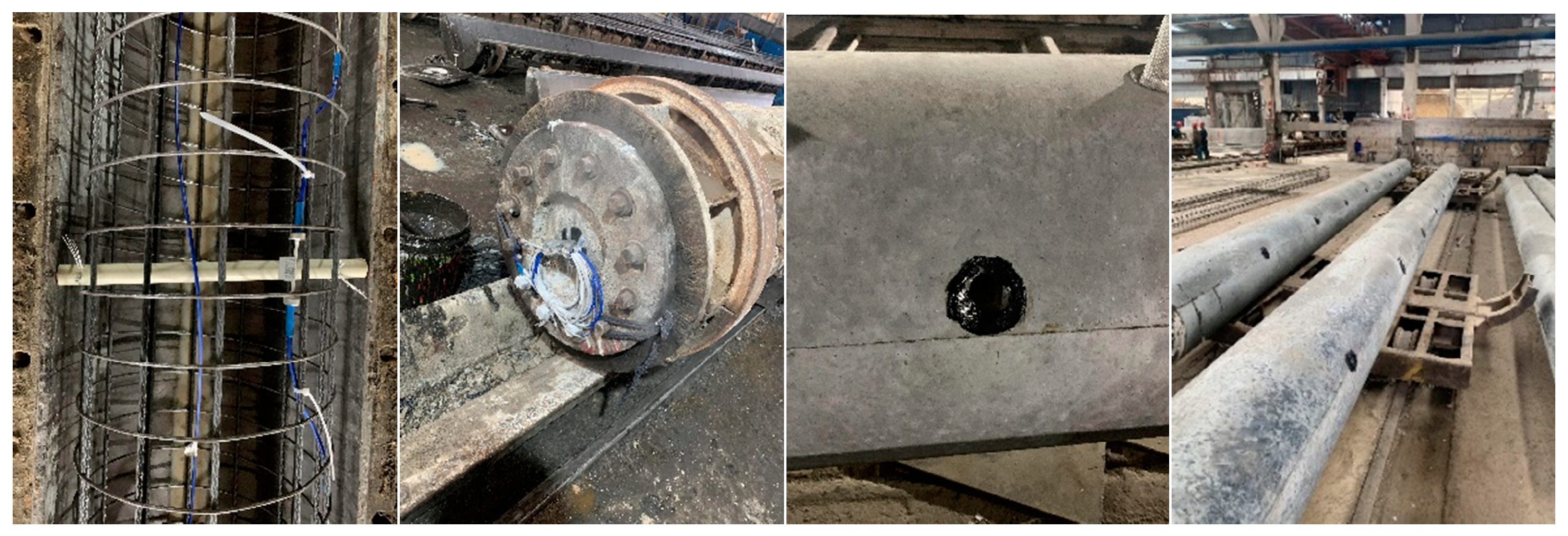
2.1. Production Process of the Vacuum Drainage Pipe Pile

The PHC pile is the most common pipe pile used in Chinese pile foundation engineering. Due to its simple production, strong load capacity, small settlement deformation, and high efficiency, it has been widely used in the field of construction engineering. Most comparative studies of new types of piles use PHC piles as a reference. Therefore, the ordinary piles used in this study were PHC piles. The main material of the VDP piles used in the test was concrete, and the concrete strength of the pile was C80 (the compressive strength of the cubic concrete block was 80 MPa). The outer diameter of the pipe pile was 500 mm, the inner diameter was 250 mm, and the pile length was 9 m. The number of holes in a single layer was 2, the spacing between the layers of holes was 1 m, and the hole diameter was 30 mm, giving 14 holes in total. The production process of VDP piles is the same as that of ordinary pipe piles (PHC piles), with the following differences: To ensure the integrity of the holes, after the reinforcement cage is placed into the mold, a PVC pipe with a length of 50 cm and an outer diameter of 3 cm is bound to the reinforcement cage using fine steel wires to form a new mold. After concrete curing, the PVC pipes are knocked out to form holes. A metal mesh with a filter membrane is inserted into the holes. Airtight glue is used to fit the metal mesh with the pile body to prevent air leakage in the vacuum process, as shown in Figure 1.

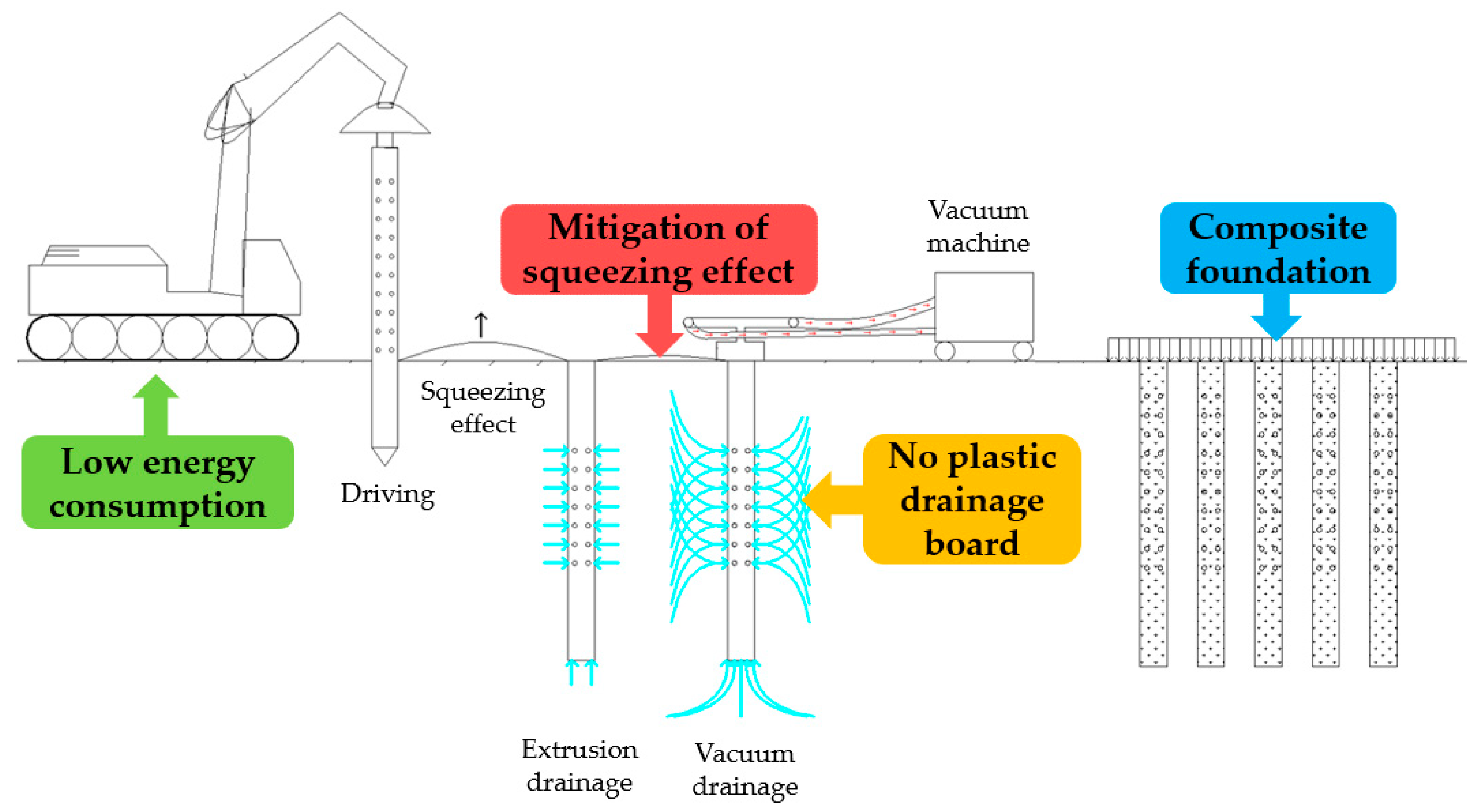
2.2. Construction Process of the Vacuum Drainage Pipe Pile

Unlike the plastic drainage board and pile foundation combined method, the construction process of the VDP piles is as follows:
(1)
When the soil is soft, the universal prefabricated pipe pile driver is used to drive the vacuum drainage pipe pile. At this time, the energy consumption required for driving the pile is low;
(2)
One uses the pile driving disturbance and its own drainage channel to reduce the soil-squeezing effect, and the other connects an external vacuum machine to accelerate drainage and consolidation;
(3)
After the soil hardens, the pile composite foundation is formed so as to jointly bear the upper load and directly serve as the engineering pile;
(4)
The plastic drainage board is not used in the process, which is environmentally friendly.
The construction and service of the vacuum drainage pipe piles are integrated, which improves the overall bearing capacity and greatly reduces the construction period, with good economic benefits, as shown in Figure 2.

3. Field Test

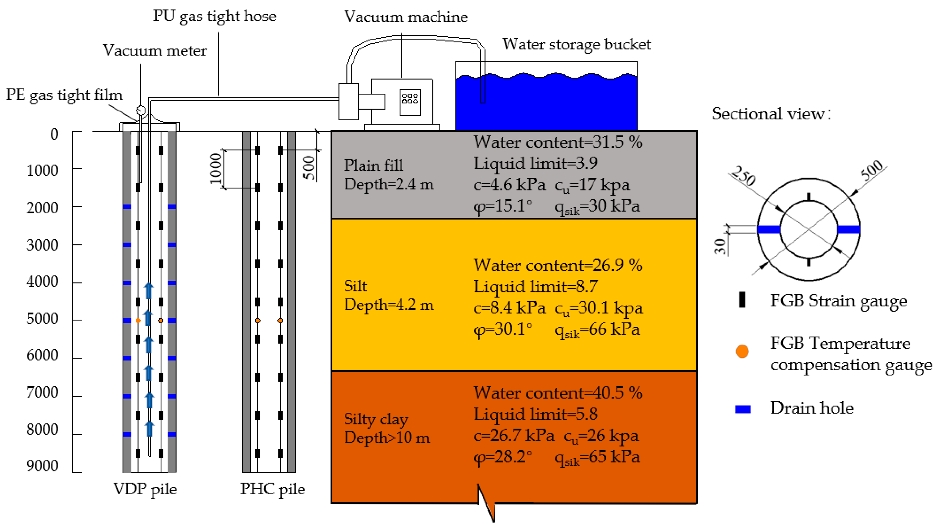
3.1. Test Site and Pile Description
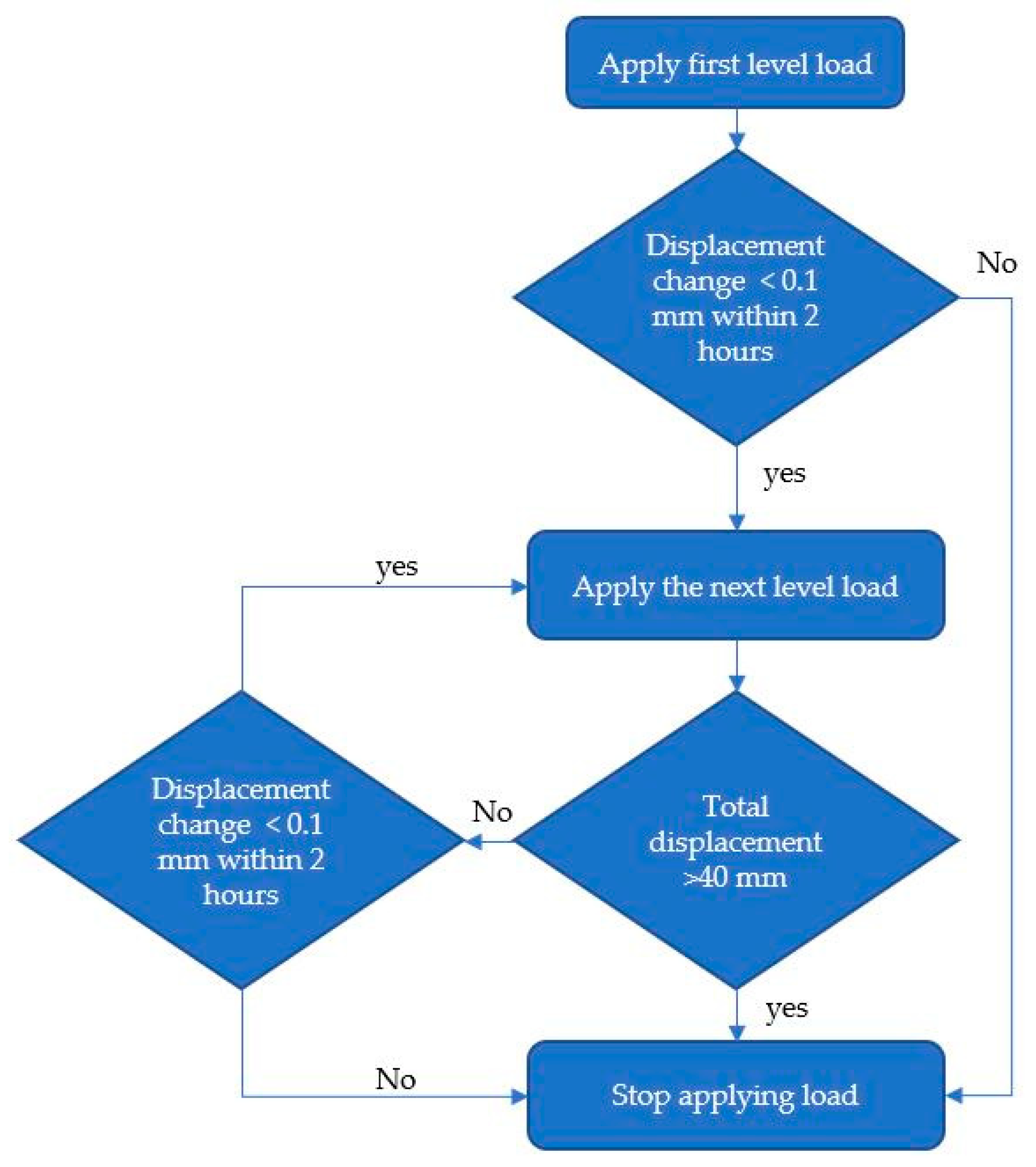
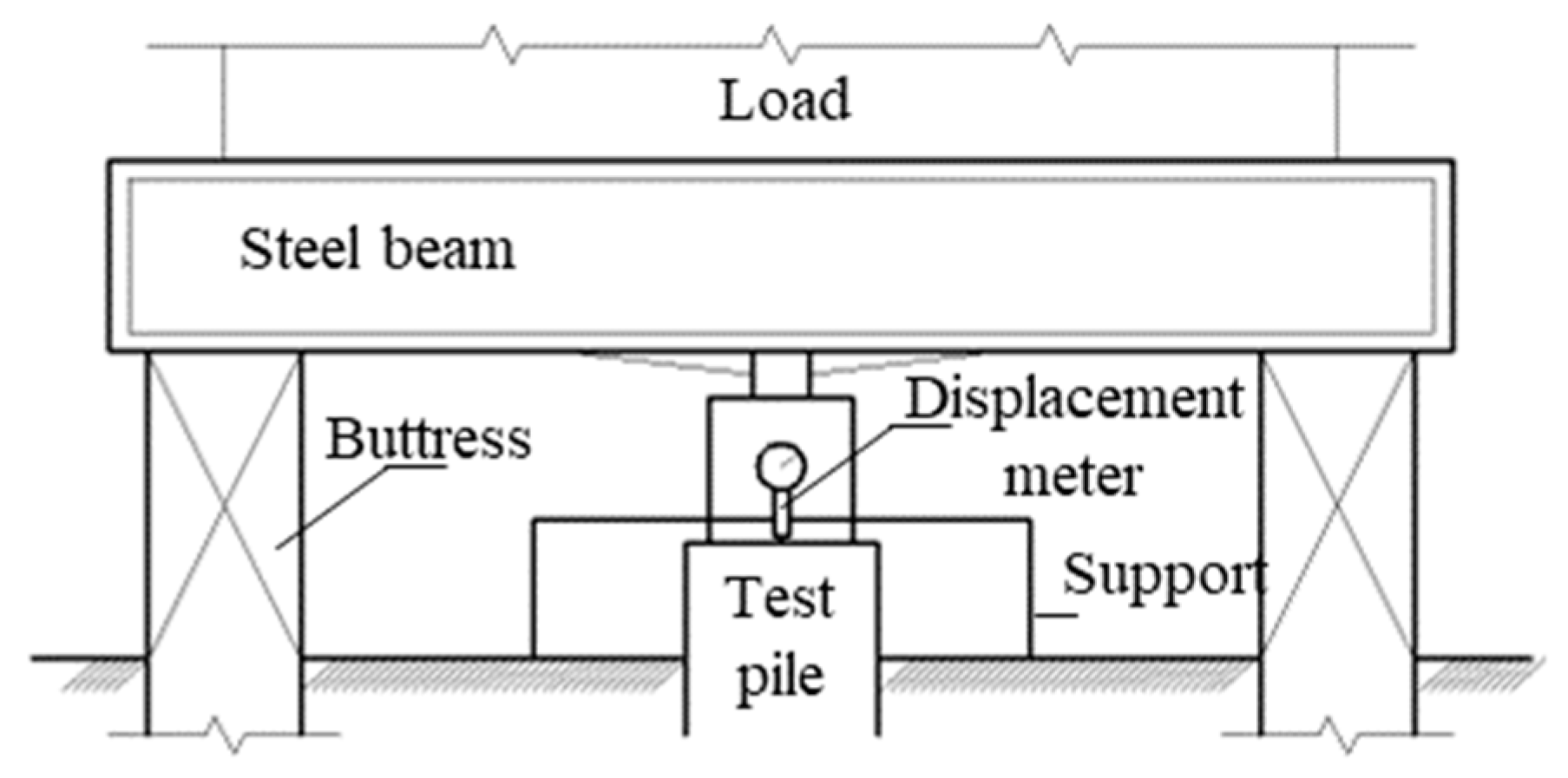
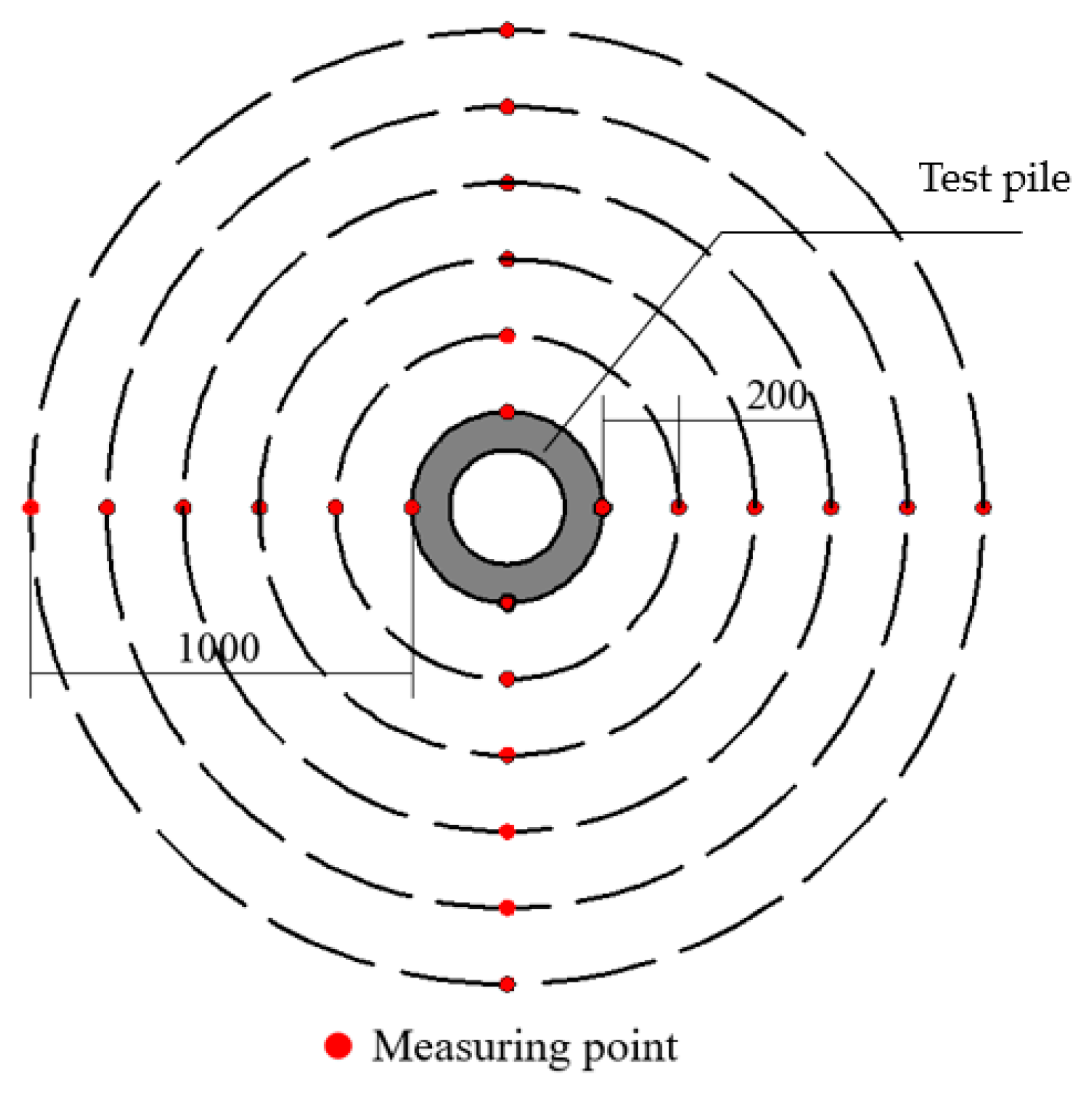
The soil parameters, vacuum method, and strain gauge distribution are shown in Figure 3. The field tests were carried out on the project site of a highway to be built in Hangzhou, Zhejiang Province. The soil layer of the site is mainly composed of plain fill, silt, and silty clay, with a groundwater-level depth of 1.8 m. To ensure the progress of the pile foundation project, the vacuum consolidation time was set at 10 days for this test, and the vacuuming time was 18 h per day for a total of 180 h. During the vacuum interval, the water inside the pile was pumped into the water storage bucket. During the vacuum period, the vacuum degree had an atmosphere of approximately 0.5~0.7. FBG (fiber Bragg grating) and had the advantages of high precision and real-time performance. A fiber grating strain gauge and fiber grating thermometer from Zhixing Technology Nantong Co., Ltd. were used in this test. The strain gauges were arranged 500 mm below the pile top with a spacing of 1000 mm. The thermometer was buried 5000 mm below the pile top.

3.2. Test Process

A single-pile static load compression test was carried out for one PHC pile and one VDP pile. For the PHC pile, the first-level load was 300 kN, and then the load for each following level was 150 kN. For the VDP pile, the first-level load was 400 kN, and the load for each following level was 200 kN. The slow maintenance load method was adopted in the test [21]. The specific process is shown in Figure 4: (1) After applying the first-level load, one measures and records the pile top displacement at 5 min, 15 min, 30 min, 45 min, and 60 min, respectively, and once every 30 min thereafter. (2) The next level of load can be applied if the displacement does not exceed 0.1 mm within two consecutive hours. (3) The loading can be terminated when the total settlement of the pile top exceeds 40 mm. The single-pile compressive static load test device is mainly composed of a surcharge, buttress, hydraulic jack, steel beam, and displacement meter, as shown in Figure 5.
To verify that the VDP pile will not produce a large relative displacement of the pile and soil during vacuum consolidation, it is necessary to monitor the surface displacement and pile top displacement of the soil around the test pile. One uses a precision total station to observe the ground settlement around the pile. The layout of the measuring points is shown in Figure 6. A total of 6 measuring points are uniformly arranged at a distance of 0 mm~1000 mm from the pile side, and the same measuring points are arranged in four vertical directions. Finally, the average displacement is taken as the surface displacement of the soil around the test pile.

3.3. Test Results

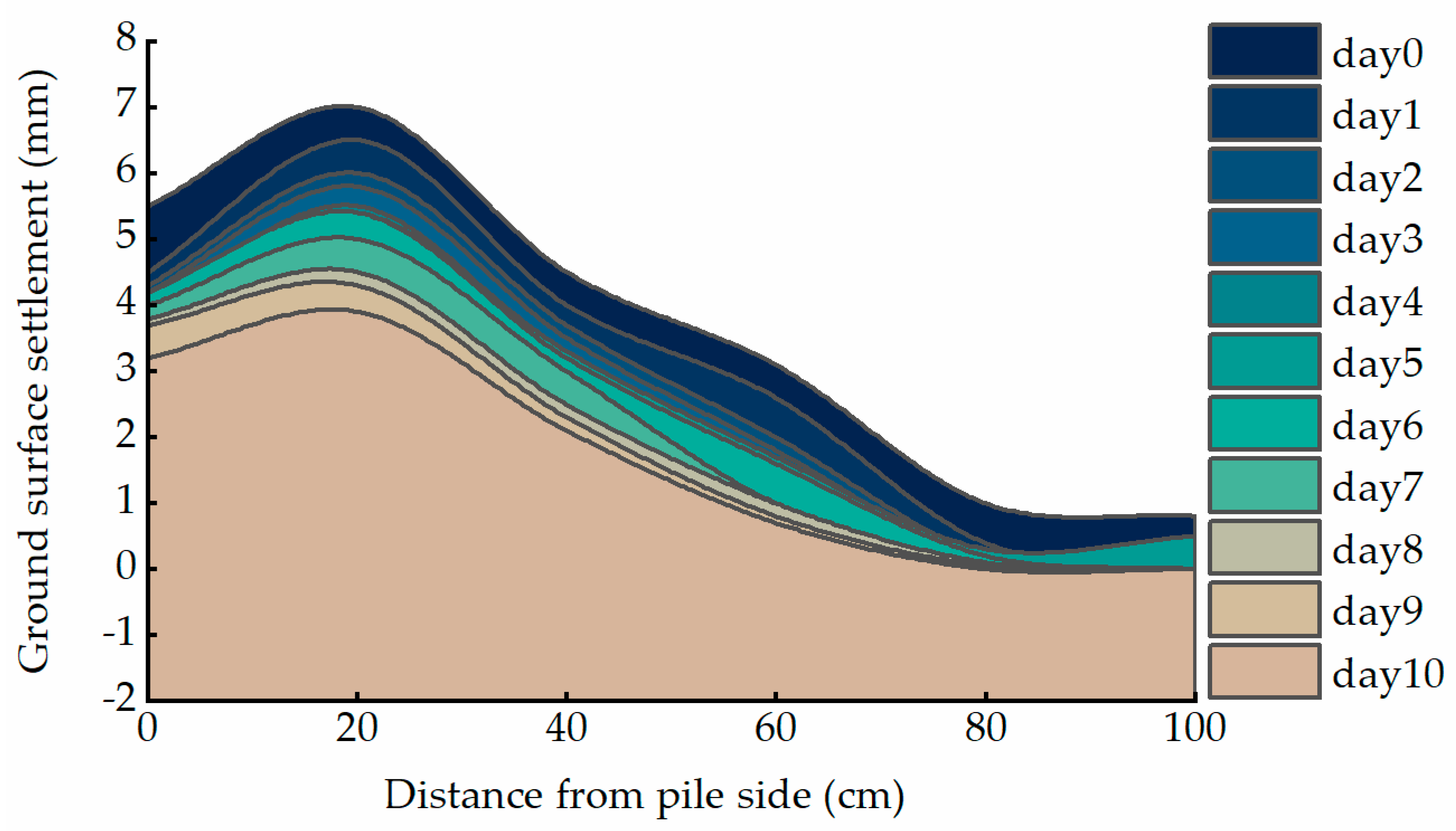
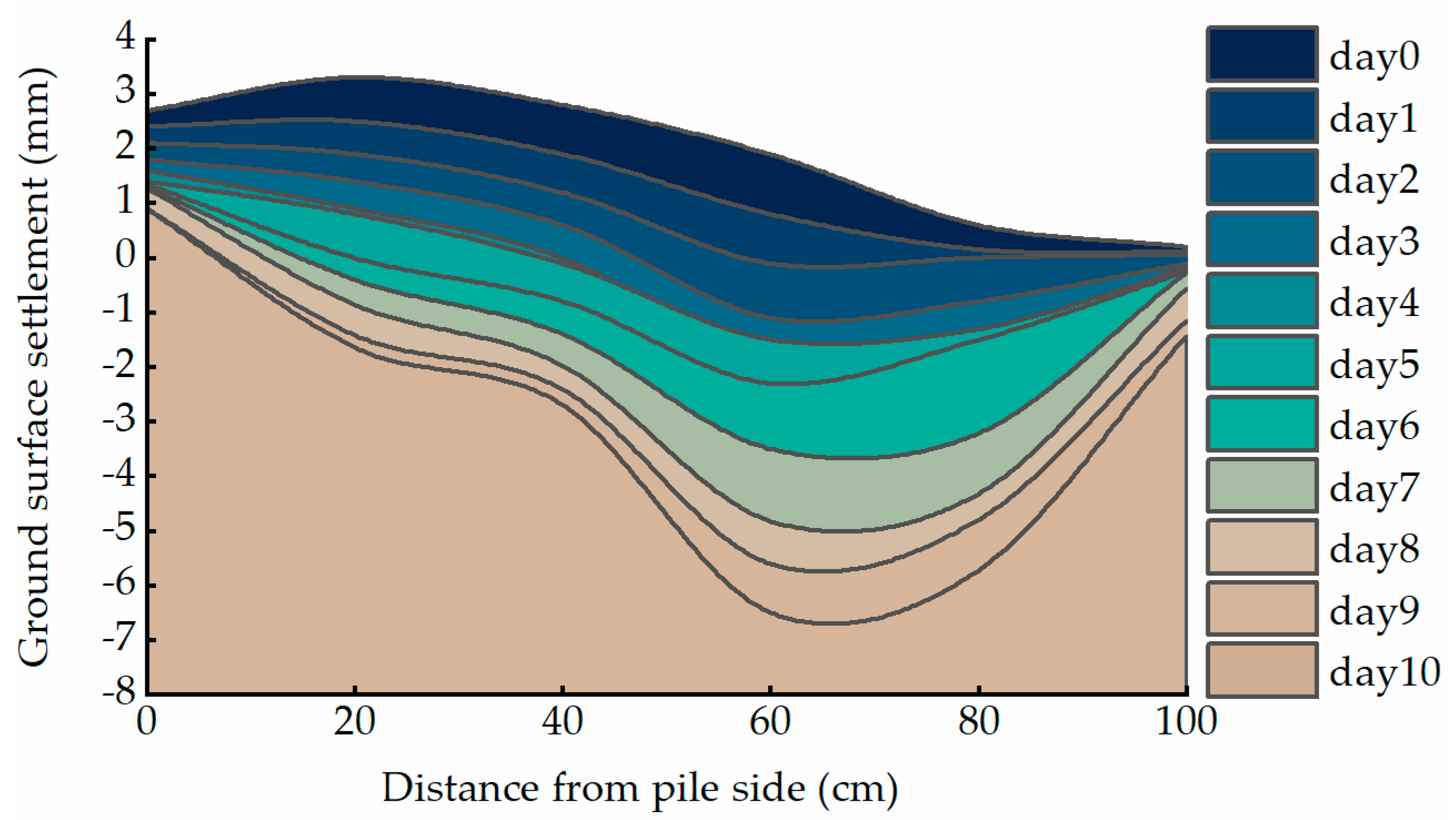
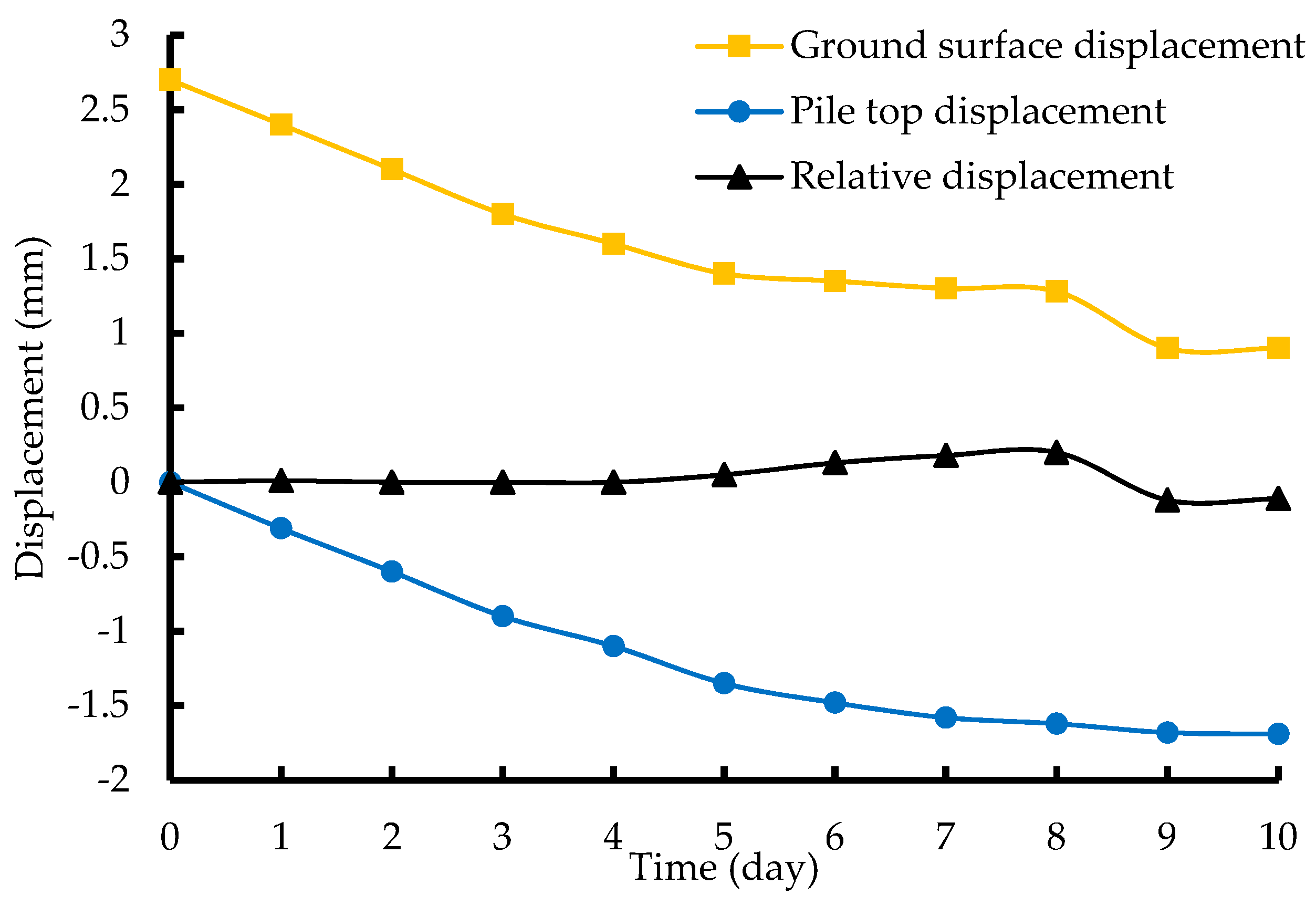
3.3.1. Surface Displacement of Soil around the Piles

Figure 7 and Figure 8 show the surface displacement curves of the soil around the PHC pile and the VDP pile, respectively. The soil surface uplift was the highest at 20 cm from the side of the PHC pile, and there was still an uplift after 10 days. This shows that the soil-squeezing effect caused by pile driving has not completely disappeared. On the 4th day, the VDP pile basically eliminated the soil squeeze and even caused a settlement of approximately 1.5 mm at the 60 cm side of the pile. From the 5th day to the 7th day, the settlement velocity of the pile-side soil of the two types of piles decreased, and the reverse arch phenomenon was observed. This is mainly due to the heavy rain on these two days, which increased the amount of pore water among the soil particles. Over time, the soil around the two types of piles continued to consolidate, and the surface uplift gradually disappeared. This development trend of soil settlement around ordinary pipe piles is basically consistent with the results of existing research; thus, the monitoring method explored in this article is effective [22,23].
If the settlement of the soil around the pile is greater than the settlement of the pile itself, this will cause negative frictional resistance. The displacement of the top of the VDP pile and the ground displacement on the 0 cm side of the pile were drawn in the same diagram, and the relative displacement curve was added (as shown in Figure 9). It can be seen from the relative displacement curve that the maximum difference between the two was 0.18 mm~−0.12 mm. The relative displacement of the pile and soil caused by the vacuum effect is almost negligible. Therefore, vacuum consolidation will not lead to excessive pile-soil displacement or negative frictional resistance.

3.3.2. Relationship between Pile Head Displacement and Load

The load-settlement curves of the PHC pile and the VDP pile are slowly changing types, as shown in Figure 10. The slope of the VDP pile curve is comparatively smaller. Throughout different stages, the VDP pile demonstrated a larger bearing capacity and anti-deformation capacity than the PHC pile. To determine the vertical ultimate bearing capacity of a single pile, the method outlined in the technical code [21] was employed. The load value corresponding to a 40 mm settlement of the pile top was considered the ultimate compressive bearing capacity. Using linear interpolation, the ultimate compressive bearing capacities of the PHC pile and the VDP pile were calculated to be 1482 kN and 1743 kN, respectively. The single-pile ultimate bearing capacity of the VDP pile was approximately 17.6% larger than that of the PHC pile.

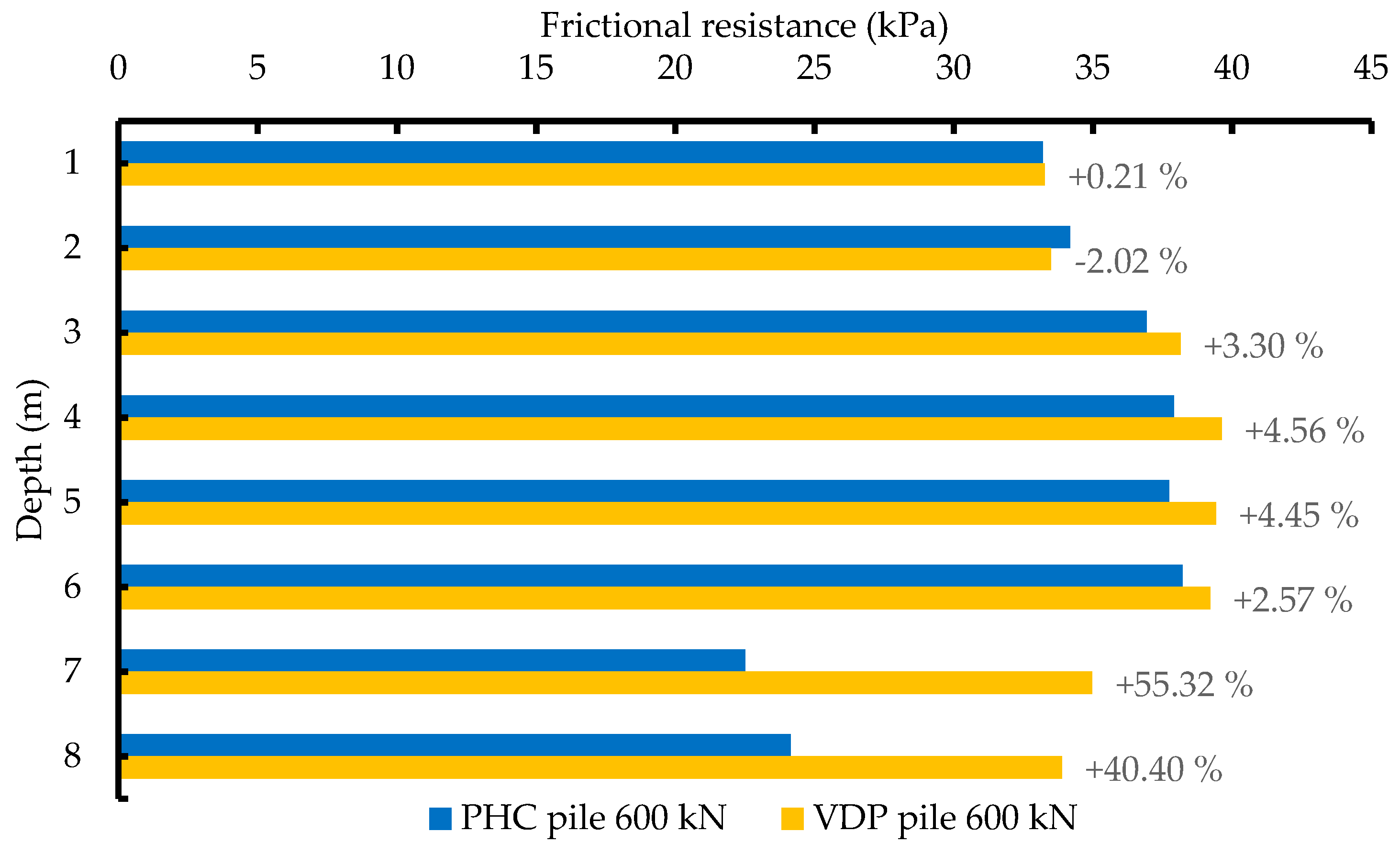
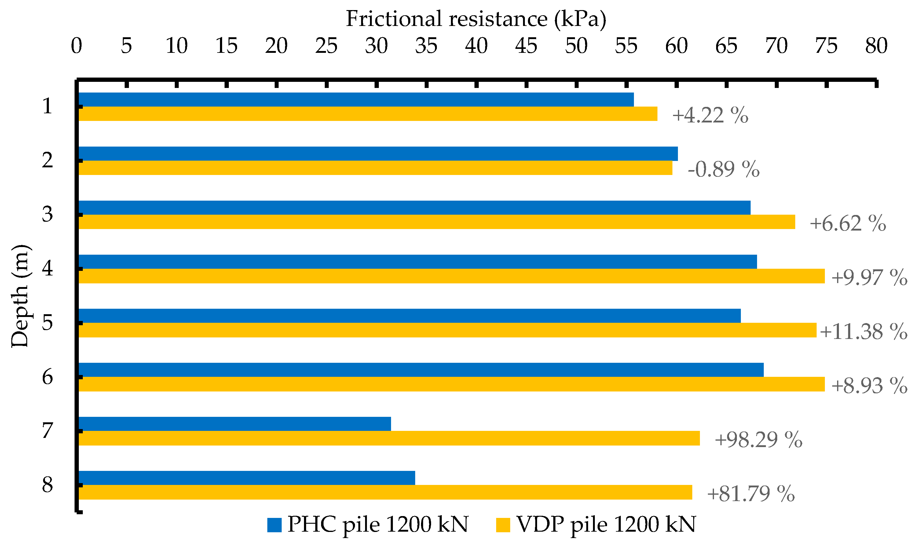
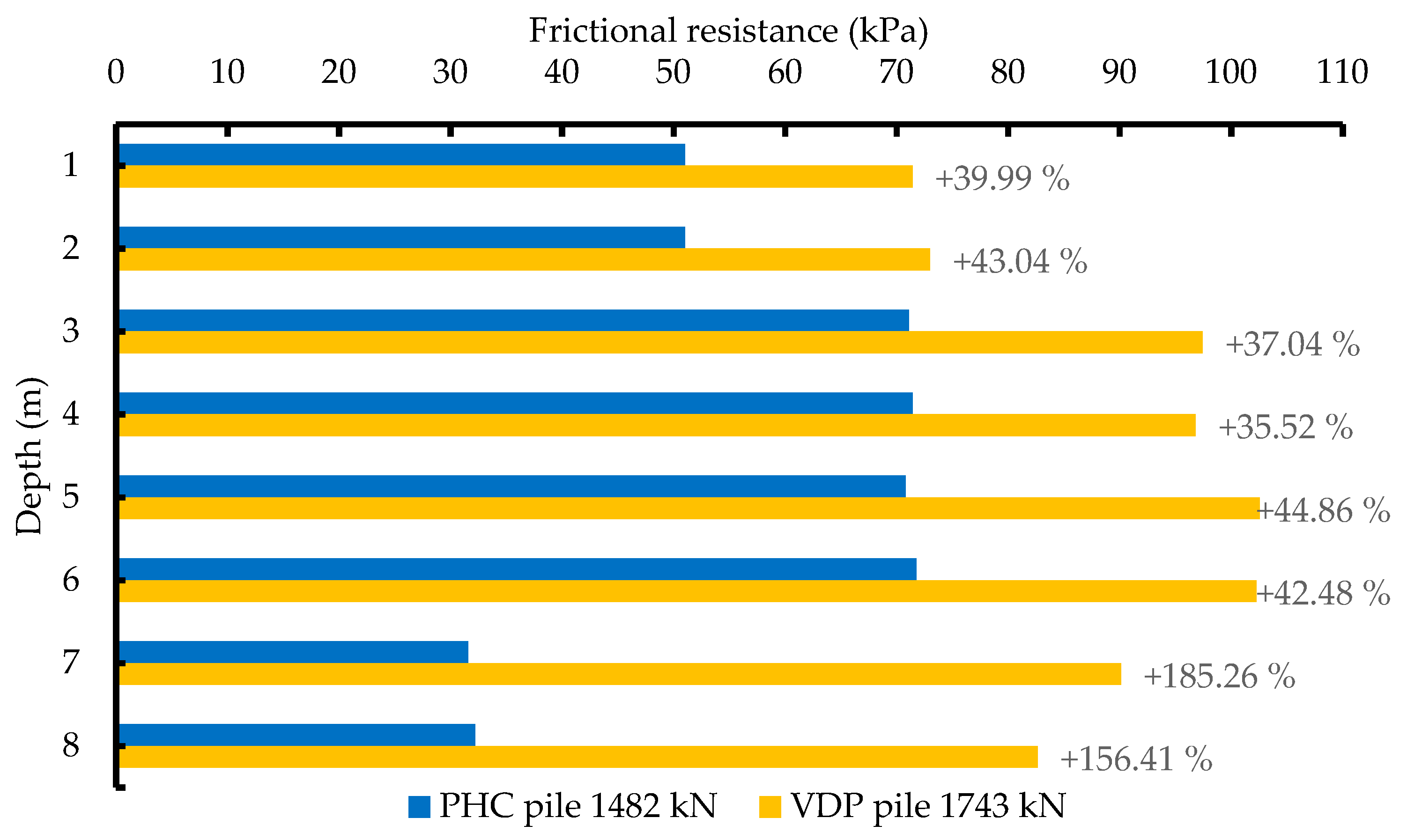
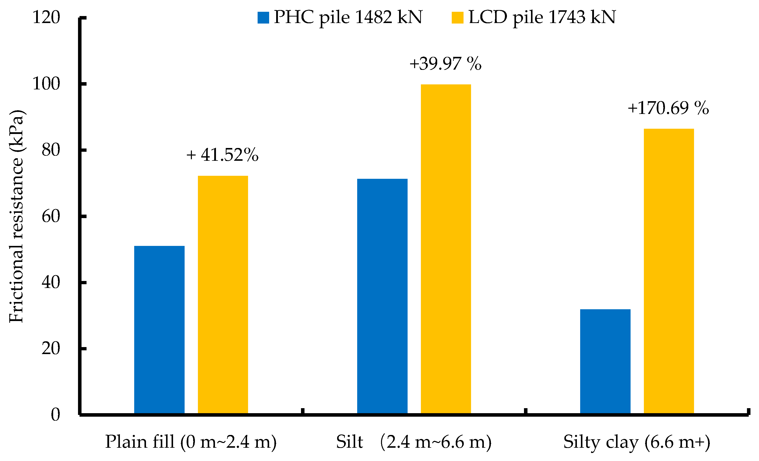
3.3.3. Analysis of the Pile Side Frictional Resistance

The pile-side friction resistance can be calculated by dividing the difference between the axial forces of two sections by the pile-side area of the section. The average pile side friction resistance of the PHC pile and VDP pile under different pile top loads is shown in Figure 11, Figure 12 and Figure 13. At a depth of 1 m~2 m, as the pile top load increased from 600 kN to 1200 kN, the friction resistance of the PHC pile and the VDP pile increased from 30 kPa~35 kPa to 55 kPa~60 kPa, but the gap between the two did not further expand. At a depth of 3 m~6 m, the friction resistance of the two piles increased from 35 kPa~40 kPa to 65 kPa~75 kPa, and the difference between them increased slightly. At a depth of 7 m~8 m, the friction resistance of the PHC pile increased from 20 kPa~25 kPa to 30 kPa~35 kPa, while the friction resistance of the VDP pile increased from 30 kPa~35 kPa to 60 kPa~65 kPa, and the difference between the two increased from 40.40~55.32% to 81.79~98.29%.
It is worth noting that when the depth was 2 m, regardless of whether the pile top load was 600 kN or 1200 kN, the lateral friction resistance of the PHC piles was higher than that of the VDP piles. This may be because groundwater has a greater impact on VDP piles compared to PHC piles, as VDP piles can be permeable. According to the geological survey report, the groundwater level was located at a depth of 1.8 m, and the frequent flow of groundwater reduced the compaction of the soil around the pile, thereby reducing the friction resistance at this depth. However, at a depth of 2 m, when the top load of the pile reached its limit, the lateral friction resistance of the VDP pile was significantly higher than that of the PHC pile. This is mainly because the ultimate load of the former was greater than that of the latter, and the pile-soil displacement was greater. Therefore, at a depth of 2 m, the soil around the pile provided more lateral friction resistance. Overall, the groundwater interface will reduce the lateral friction resistance of vacuum drainage pipe piles, but as the pile top load gradually increases to the ultimate load, this impact will gradually decrease.
The distribution of pile-side frictional resistance under the ultimate load is shown in Figure 13. The frictional resistance of the VDP pile mainly acts on the middle and lower parts of the pile, and the distribution is more uniform than that of the PHC pile. For the PHC pile, at depths of 7 m~8 m, the pile side frictional resistance is only 30 kPa~35 kPa, while the lateral friction resistance of the VDP pile can reach 80 kPa~90 kPa. This indicates that vacuum consolidation can greatly enhance the lateral friction resistance near the bottom of the pile, greatly improving the load transfer efficiency of the pile body.
To further analyze the influence of the soil layers on the side friction resistance, the average side friction resistance of different soil layers was calculated using the difference method. The depth of the plain fill was 0 m~2.4 m, the depth of the silt was 2.4 m~6.6 m, and the depth of the silty clay was more than 6.6 m. The distribution of pile side friction resistance for the two piles according to the soil layer is shown in Figure 14. It can be seen that compared with the PHC pile, the pile side friction resistance of the VDP pile to the silty clay layer is greatly increased, with an increase of 170.69%. For the other two soil layers, there is also an increase of nearly 40%. Therefore, the vacuum consolidation effect of the VDP pile can improve the pile side friction resistance, and the lifting effect is more apparent for the soil layer with a worse structure.

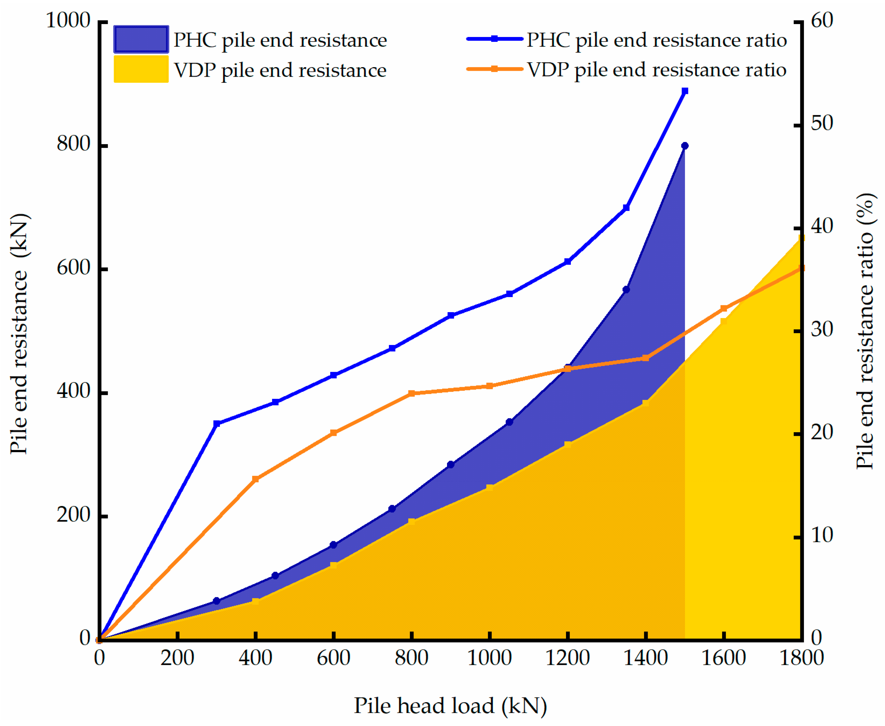
3.3.4. Analysis of the Pile end Resistance

The pile end resistance ratio can be defined as the ratio of the pile bottom resistance to the top pile load, which is used to analyze the bearing characteristics of the pile foundation and determine the pile type classification. In this field test, no pressure sensor was installed at the pile end, and the pile end resistance was approximately calculated by subtracting the total side friction from the pile top load. The relationship between the pile end resistance ratios of the PHC and VDP is shown in Figure 15.
In the initial stage of pile top load loading, the rising slopes of the two pile types are basically the same. When the load on the top of the pile exceeds 750 kN, the increase in the pile-end resistance of the VDP pile levels off. At this time, further pile-side frictional resistance develops so as to bear the load. The slope of the PHC pile is basically unchanged, and the load is borne mostly by the pile bottom. When approaching the ultimate load, both slopes increase, the pile end resistance of PHC changes abruptly, and the pile end resistance ratio exceeds 50% at the last level of loading, which can be determined as the frictional end bearing pile, dominated by end bearing. On the contrary, the slope of the VDP pile is increased, but it is basically consistent with the initial stage of load loading. There is no sudden change, and the final pile-end resistance ratio is less than 40%. It can be determined as an end-bearing friction pile, dominated by pile-side frictional resistance.

4. Carbon Emission Estimation for the Whole Process of the VDP Pile

The carbon emissions of pile foundation projects refer to the total amount of greenhouse gas emitted into the external environment as building materials and energy are consumed throughout the whole life cycle, from production and transportation to the construction of piles. The calculation method is the total consumption of materials or energy multiplied by the carbon emission factor, which can be estimated according to Equation (1). The carbon emission factors used in this paper refer to the IPCC Guidelines for the National Greenhouse Gas Emission Inventory and the Chinese Academy of Engineering.
C = i = 1 m M i × F ( M i ) + j = 1 n E i × F ( E i )
where
C is the total carbon emission (kg);
M i is the total consumption of the i-th material in engineering (kg);
F ( M i ) is the carbon emission factor of the i-th material (kg/kg);
E i is the total consumption of the j-th energy in engineering (kg, kW·h);
F ( E j ) is the carbon emission factor of the j-th energy (kg/unit).
The material of the pile body is mainly composed of concrete and steel; the material of the plastic drainage board is mostly PVC; and the metal mesh for the VDP piles is steel. The energy data required for transportation is taken from the China Transportation Yearbook 2021 [24]. The materials and energy consumption required for construction are calculated according to the Budget Quota of Electric Power Construction Project [25] and the Quota of Construction Machinery Shift Cost of Electric Power Construction Project [26].
Taking the working conditions of this field test as an example, for the treatment of a 10,000 m2 soft soil foundation, if the combined method of common piles and drainage boards is used, the pile spacing is 2.5 m, 1600 piles with a diameter of 0.5 m and a length of 9 m are required, and 1600 plastic drainage boards with a length of 15 m are added. If VDP piles are used, the pile spacing is 3 m, and 1111 piles with a diameter of 0.5 m and a length of 9 m are required. The bearing capacity of VDP piles is higher than that of PHC piles; thus, the pile spacing can be appropriately increased. For soft soil, when the pile spacing exceeds a diameter of 5, the pile group effect coefficient will be approximately 1.3 [27].
The carbon emission factor refers to the amount of greenhouse gas generated when consuming a unit mass of substance and is an important parameter that characterizes the greenhouse gas emission characteristics of a certain substance [28]. In the estimation of carbon emissions, the selection and determination of carbon emission factors are crucial. The carbon emissions of pile foundation engineering materials mainly derive from two sources: one is direct or indirect emissions generated through the use of energy, and the second is direct emissions generated through the chemical reactions of raw materials. The carbon emissions from the first source can be calculated based on production energy consumption statistics obtained by multiplying the energy usage by the carbon emission factor. The carbon emissions from the second source can be estimated by comprehensively considering the carbon content of the material and the chemical reaction process.
In the production of PHC piles, the steel bars and spiral bars are made of cold-drawn low-carbon steel wire; and the circular bars, the end plates, and the pile sleeves are made of Q235 steel. Considering the process and technical level of domestic steel production, the carbon emission factor of the steel used for PHC piles can be taken as 2.0 (kg/kg) [29].
The concrete strength of PHC piles is generally C80, and currently, there is no carbon emission factor for C80 concrete in the data. Therefore, according to the law of carbon emission factors for C20, C30, C40, and C50, the carbon emission factor for C80 can be recursively calculated to be 470 (kg/m3) [30].
The carbon emission factor of energy includes the total carbon emissions per unit mass of energy in various stages of acquisition, processing, and use. The main types of energy consumed in pile foundation engineering are coal, electricity, and diesel. The carbon emission factors for energy are as follows: coal has a carbon emission factor of 0.73 (kg/kg), electricity has a carbon emission factor of 0.28 (kg/kW·h), and diesel has a carbon emission factor of 0.59 (kg/kg) [31].
The results regarding the carbon emissions for the common piles and drainage boards throughout the whole process of the combined method are shown in Table 1, and the results regarding the carbon emissions of the VDP piles throughout the whole process are shown in Table 2. Regarding total carbon emissions, the VDP pile method can lead to a reduction of 31.4%, and the main factor for reducing carbon emissions is the reduced use of piles. In addition, the energy consumption of the whole process is also decreased, with 6.8 tons of diesel oil, 13.9 tons of coal, and 8678 kw·h of electricity. Therefore, compared with traditional methods, the VDP pile treatment of soft soil foundations reduces the use of pile foundations, which conforms to the development principles and models of a circular and low-carbon economy. It reduces carbon emissions and helps to protect the ecological environment. In addition, it reduces energy consumption and promotes the sustainable development of the project.

5. Conclusions

To further explore the bearing capacity and sustainable construction of vacuum drainage pipe (VDP) piles, a VDP pile and a PHC pile with a pile length of 9 m and a pile diameter of 500 mm were fabricated. The field test was carried out on a site composed of fill, silt, and silty clay. The ultimate single-pile bearing capacity, pile side friction, and pile end resistance of the PHC piles and VDP piles were compared and analyzed. The effects of the VDP pile on energy conservation and emission reduction in practical projects were discussed. This study thus provides guidance for the production and design of VDP piles in the future. The following conclusions were drawn:
  • The monitoring results of the total station showed that, in the vacuum consolidation stage, the relative displacement of the pile and soil for the VDP pile was less than 0.5 mm, which is almost negligible. After 4 days, the squeezing effect could basically be eliminated, while the PHC pile still had a protrusion of 3~4 mm on the 10th day. This indicates that VDP pipe piles can alleviate the squeezing effect;
  • In this field test, the ultimate bearing capacity of a single VDP pile was 1743 kN, and that of the PHC pile was 1482 kN, an increase of 17.6%. The VDP pile can improve the bearing capacity of a single pile. This is mainly because the VDP pile enhances the side friction of the pile;
  • Compared with the PHC pile, the pile side friction resistance of the VDP pile to the silty clay layer was increased by 170.69%, and the vacuum consolidation effect was more apparent for the soil layer with a poor structure. When the load on the pile top reached the limit, the pile end resistance ratio of the VDP pile was less than that of the PHC pile, and the bearing capacity was mainly provided by friction. Vacuum consolidation can compact the pile and soil, which increases the frictional resistance at the pile-soil interface;
  • Regarding total carbon emissions, the VDP pile method can lead to a reduction of 31.4% compared with the traditional method, and the main factor influencing this reduction is the reduced use of piles. The energy consumption is also less than that of the traditional method, which conforms to the principle of low-carbon sustainable development.

Author Contributions

Conceptualization, W.-K.L. and X.-W.T.; methodology, W.-K.L.; software, W.-K.L. and K.-Y.L.; validation, W.-K.L., X.-W.T., and Y.Z.; formal analysis, J.-X.L.; investigation, W.-K.L.; resources, W.-K.L.; data curation, Y.Z.; writing—original draft preparation, W.-K.L.; writing—review and editing, X.-W.T.; visualization, Y.Z.; supervision, X.-W.T.; project administration, X.-W.T.; funding acquisition, X.-W.T. All authors have read and agreed to the published version of the manuscript.

Funding

This work was funded by the Zhejiang Province Public Welfare Technology Application Research Project (LGG22E080002), the Key Water Science and 477 Technology Project of Zhejiang Province (RB2027), and the Cultural Heritage Bureau of Zhejiang Province (2023006).

Institutional Review Board Statement

Not applicable.

Informed Consent Statement

Not applicable.

Data Availability Statement

Not applicable.

Acknowledgments

The authors express their gratitude to the construction department of Hongyang Construction Co., Ltd. for contributing to the construction of the test piles and assistance with the static load tests and to the vacuum equipment production department of Jiangsu Xintai Rock Technology Co., Ltd. for contributing to the vacuum equipment supply and installation. The authors also express their gratitude to the pile production department of Zhejiang Xinye Pipe Pile Co., Ltd. for contributing to the production and transportation of the pipe piles and to the sensor production department of Zhixing Technology Nantong Co., Ltd. for contributing to the sensor installation and technical guidance.

Conflicts of Interest

The authors declare no conflict of interest.

Abbreviations: Notation

C Total carbon emissions (kg);
M i Total consumption of the i-th material in engineering (kg);
F ( M i ) The carbon emission factor of the i-th material (kg/kg);
E i Total consumption of the j-th energy in engineering (kg, kW·h);
F ( E j ) The Carbon emission factor of the j-th energy (kg/unit).

References

  1. Mesri, G. Discussion of “Field study of pile—Prefabricated vertical drain (PVD) interaction in soft clay”. Can. Geotech. J. 2021, 58, 747. [Google Scholar] [CrossRef]
  2. Wu, Y.; Fang, L.; Li, X.; Hu, S. Technical discussion on tube pile combined with prefabricated strip drain to soft soil treatment. Chin. J. Rock Mech. Eng. 2006, 25, 3572–3576. (In Chinese). Available online: https://www.cnki.com.cn/Article/CJFDTOTAL-YSLX2006S2035.htm (accessed on 1 October 2006).
  3. Cakiroglu, C.; Islam, K.; Bekdaş, G.; Kim, S.; Geem, Z.W. CO2 Emission Optimization of Concrete-Filled Steel Tubular Rectangular Stub Columns Using Metaheuristic Algorithms. Sustainability 2021, 13, 10981. [Google Scholar] [CrossRef]
  4. Zavadskas, E.K.; Antucheviciene, J.; Vilutiene, T.; Adeli, H. Sustainable Decision-Making in Civil Engineering, Construction and Building Technology. Sustainability 2018, 10, 14. [Google Scholar] [CrossRef]
  5. Umaiyan, U.; Muthukkumaran, M. Improved radial consolidation in soft clay using pervious concrete piles. Civil Eng.-Geotech. 2022. [Google Scholar] [CrossRef]
  6. Ni, P.; Mangalathu, S.; Mei, G. Compressive and flexural behaviour of reinforced concrete permeable piles. Eng. Struct. 2017, 147, 316–327. [Google Scholar] [CrossRef]
  7. Chen, Z.; Wang, B.; Wang, C.; Wang, Y.; Xiao, P.; Li, K. Performance of a Subgrade-Embankment-Seawall System Reinforced by Drainage PCC Piles and Ordinary Piles Subjected to Lateral Spreading. Geofluids 2023, 2023, 4489478. [Google Scholar] [CrossRef]
  8. Deng, Y.; Zhang, R.; Sun, J. Novel technology of statical-drill and rooted drainage pile and its large-scale model test. J. Build. Struct 2022, 43, 293–302. (In Chinese) [Google Scholar] [CrossRef]
  9. Miranda, M.; Da, C.; Castro, J. Influence of geotextile encasement on the behaviour of stone columns: Laboratory study. Geotext. Geomembr. 2017, 45, 14–22. [Google Scholar] [CrossRef]
  10. Poornachandra, V.; Venkataraman, P.; Krishna, P.B. Discrete element method to investigate flexural strength of pervious concrete. Constr. Build. Mater. 2022, 323, 126477. [Google Scholar] [CrossRef]
  11. Tan, X.; Cai, M.; Feng, L. Numerical Study on Mechanical Behaviors of Geotextile-wrrapped Stone Column. China J. Highw. Transp. 2020, 33, 136–145. (In Chinese) [Google Scholar] [CrossRef]
  12. Tang, X.; Yu, Y.; Zhou, L. A Prefabricated Pipe Pile with Drainage and Enlarged Friction Resistance and Its Construction Method. CN Patent 104846809A, 19 August 2015. (In Chinese). [Google Scholar]
  13. Tang, X.; Zou, Y.; Lin, W. Model experiment on improving bearing capacity of perforated pipe piles by vacuum consolidation. J. Zhejiang Univ. (Eng. Sci.) 2022, 56, 1320–1327. (In Chinese) [Google Scholar] [CrossRef]
  14. Tang, X.; Lin, W.; Zou, Y. Experimental study of the bearing capacity of a drainage pipe pile under vacuum consolidation. J. Zhejiang Univ.-Sci. A (Appl. Phys. Eng.) 2022, 23, 639–651. [Google Scholar] [CrossRef]
  15. Li, X.J.; Zheng, Y.D. Using LCA to research carbon footprint for precast concrete piles during the building construction stage: A China study. J. Clean. Prod. 2019, 245, 118754. [Google Scholar] [CrossRef]
  16. Kwok, K.Y.G.; Kim, J.; Chong, W.K.; Ariaratnam, S.T. Structuring a comprehensive carbon-emission framework for the whole lifecycle of building, operation, and construction. J. Archit. Eng. 2016, 22, 04016006. [Google Scholar] [CrossRef]
  17. Du, Q.; Chen, Q.; Yang, R. Forecast carbon emissions of provinces in China based on logistic model. Resour. Environ. Yangtze Basin. 2003, 22, 143–150. [Google Scholar] [CrossRef]
  18. Li, X.; Wang, C.; Kassem, M.A.; Wu, S.-Y.; Wei, T.-B. Case Study on Carbon Footprint Life-Cycle Assessment for Construction Delivery Stage in China. Sustainability 2022, 14, 5180. [Google Scholar] [CrossRef]
  19. Ni, P.; Mangalathu, S.; Mei, G.; Zhao, Y. Permeable piles: An alternative to improve the performance of driven piles. Comput. Geotech. 2017, 84, 78–87. [Google Scholar] [CrossRef]
  20. Ni, P.; Mangalathu, S.; Mei, G.; Zhao, Y. Laboratory investigation of pore pressure dissipation in clay around permeable piles. Can. Geotech. J. 2018, 55, 1257–1267. [Google Scholar] [CrossRef]
  21. JGJ106-2014; Technical Code for Testing of Building Foundation Piles. Ministry of Housing and Urban-Rural Construction of the People’s Republic of China: Beijing, China, 2014. (In Chinese)
  22. Sun, Y.; Li, Z. Study on Design and Deformation Law of Pile-Anchor Support System in Deep Foundation Pit. Sustainability 2022, 14, 12190. [Google Scholar] [CrossRef]
  23. Le, X.; Cui, X.; Zhang, M.; Xu, Z.; Dou, L. Behavior Investigation of Necking Pile with Caps Assisted with Transparent Soil Technology. Sustainability 2022, 14, 8681. [Google Scholar] [CrossRef]
  24. Ministry of Transport of People’s Republic of China. China Transportation Yearbook 2021; China Communications Press: Beijing, China, 2021. [Google Scholar]
  25. National Energy Administration. Budget Quota of Electric Power Construction Project; China Electric Power Press: Beijing, China, 2018. [Google Scholar]
  26. China Electricity Council. Quota of Construction Machinery Shift Cost of Electric Power Construction Project; China Electric Power Press: Beijing, China, 2020. [Google Scholar]
  27. Liu, J. Group Effects and Some Problems on the Concept Design of Pile Group Foundation Under Vertical Load. China Civ. Eng. J. 2004, 37, 78–83. [Google Scholar] [CrossRef]
  28. Gurvich, A.; Creamer, G.G. Overallocation and Correction of Carbon Emissions in the Evaluation of Carbon Footprint. Sustainability 2021, 13, 13613. [Google Scholar] [CrossRef]
  29. Zhang, X.; Wang, F. Assessment of embodied carbon emissions for building construction in China: Comparative case studies using alternative methods. Energy Build. 2016, 130, 330–340. [Google Scholar] [CrossRef]
  30. Roh, S.; Tae, S.; Kim, R.; Park, S. Probabilistic Analysis of Major Construction Materials in the Life Cycle Embodied Environmental Cost of Korean Apartment Buildings. Sustainability 2019, 11, 846. [Google Scholar] [CrossRef]
  31. Chen, K.H. Research on Carbon Emission Accounting in the Construction Delivery Stage of Building Engineering. Ph.D. Thesis, Guangdong University of Technology, Guangzhou, China, 2014. [Google Scholar]
Figure 1. Production process of the vacuum drainage pipe pile.
Sustainability 15 07555 g001
Figure 2. The construction and service of the vacuum drainage pipe pile.
Sustainability 15 07555 g002
Figure 3. Soil parameters and pile parameters.
Sustainability 15 07555 g003
Figure 4. The flow chart of the slow maintenance load method.
Sustainability 15 07555 g004
Figure 5. Overview of the static load tests.
Sustainability 15 07555 g005
Figure 6. The layout of the measuring points (unit: mm).
Sustainability 15 07555 g006
Figure 7. Surface displacement of the soil around the PHC pile.
Sustainability 15 07555 g007
Figure 8. Surface displacement of the soil around the VDP pile.
Sustainability 15 07555 g008
Figure 9. Relative displacement curve.
Sustainability 15 07555 g009
Figure 10. Load-settlement curve of pile.
Sustainability 15 07555 g010
Figure 11. Distribution of pile side frictional resistance when the pile top load is 600 kN.
Sustainability 15 07555 g011
Figure 12. Distribution of pile side frictional resistance when the pile top load is 1200 kN.
Sustainability 15 07555 g012
Figure 13. Distribution of pile side frictional resistance when the pile top load is the ultimate load.
Sustainability 15 07555 g013
Figure 14. Distribution of pile side frictional resistance according to the soil layer.
Sustainability 15 07555 g014
Figure 15. The pile end resistance of the piles.
Sustainability 15 07555 g015
Table 1. Carbon emissions of PHC piles and plastic drainage boards.
ProjectUnitMaterial or Energy ConsumptionEmission Factor (kg/Unit)Carbon Emissions
(kg)
FabricationTransportConstructionTotal
Concretem32128\\21284701,000,160
Steelkg252,160\1942254,1022508,204
PVCkg3000\\30006.7920,370
Diesel oilkg\570412,86218,5660.5910,953
Electricitykw·h19,420\858028,0000.287840
Coalkg45,431\\45,4310.7333,164
Total carbon emissions for the whole process1,580,693
Table 2. Carbon emissions of VDP piles.
ProjectUnitMaterial or Energy ConsumptionEmission Factor (kg/Unit)Carbon Emissions
(kg)
FabricationTransportConstructionTotal
Concretem31478\\1478470694,660
Steel kg175,405\1942177,3472354,694
Diesel oilkg\3960776111,7210.596915
Electricitykw·h13,480\584219,3220.285410
Coalkg31,537\\31,5370.7323,022
Total carbon emissions in the whole process1,084,701
Disclaimer/Publisher’s Note: The statements, opinions and data contained in all publications are solely those of the individual author(s) and contributor(s) and not of MDPI and/or the editor(s). MDPI and/or the editor(s) disclaim responsibility for any injury to people or property resulting from any ideas, methods, instructions or products referred to in the content.

