Article

Redesigning for Disassembly and Carbon Footprint Reduction: Shifting from Reinforced Concrete to Hybrid Timber–Steel Multi-Story Building

by
Mauricio Morales-Beltran
1,*,
Pınar Engür
1,
Ömer Asım Şişman
2 and
Gizem Nur Aykar
1
1
Department of Architecture, Yasar University, 35100 Izmir, Turkey
2
Department of Civil Engineering, Gebze Technical University, 41400 Kocaeli, Turkey
*
Author to whom correspondence should be addressed.
Sustainability 2023, 15(9), 7273; https://doi.org/10.3390/su15097273
Submission received: 31 December 2022 / Revised: 17 March 2023 / Accepted: 31 March 2023 / Published: 27 April 2023
(This article belongs to the Special Issue Environmentally Adaptive Architecture and Eco Technologies)

Abstract

:
To reduce carbon emissions, holistic approaches to design, plan, and build our environment are needed. Regarding multi-story residential buildings, it is well-known that (1) material choices and construction typologies play a fundamental role in the reduction of carbon footprint, (2) shifting from concrete to timber will reduce significantly the carbon footprint, and (3) a building designed to be disassembled will increase the potential of achieving zero-carbon emissions. However, little has been said about the consequences of such shifts and decisions in terms of building architecture and structural design, especially in seismic-prone regions. In this study, an existing 9-story reinforced concrete (RC) multi-story residential building is redesigned with cross-laminated timber floors and glue-laminated timber frames for embodied carbon reduction purposes. Firstly, the reasons behind design decisions are addressed in terms of both architecture and structure, including the incorporation of specially steel concentrically braced frames for seismic-resistance. Then, the outcomes of life cycle assessments and pushover analyses show that the RC residential building emits two times more carbon than the hybrid steel-timber residential building, and that while the hybrid building’s lateral load-capacity is less than in the RC building, its deformation capacity is higher. These results highlight the relevance of considering the carbon footprint in combination with the design decisions, which seems to be the key to introducing circular projects in seismic-prone areas.

1. Introduction

Since the industrial revolution, human activities have been exponentially producing carbon dioxide (CO2), and today the excessive amount concentrated in the atmosphere is warming up the planet and irreversibly altering the environment [1,2,3]. Simultaneously, the extended urbanizations resulting from an increasing global population and the predominance of linear economic models, under which products are designed for a single use, are exhausting our natural resources. Apart from its significant role in generating vast amounts of waste, the building construction sector, alone, is responsible for 35–40% of the global energy consumption and its associated carbon emissions [4,5,6,7,8]. Since embodied carbon emissions are released into the environment during the whole lifecycle of a building, i.e., production of materials, transportation, construction, assembly, replacement, and deconstruction phases, focusing on reducing buildings’ embodied carbon footprints could, therefore, mitigate the negative environmental impacts of the construction sector [9,10]. However, buildings are responsible for carbon emissions throughout their lifecycle: 76% are operational carbon emissions, resulting from the energy consumed for heating, cooling, and lighting during building occupancy, and 24% are embodied carbon emissions, resulting from the energy consumed during production and construction phases during the lifecycle stages of a building [8]. Until recently, operational energy was deemed the main contributor in the environmental impact of buildings, which explains the large number of studies aiming at reducing it [11]. However, unlike operational carbon emissions, the embodied carbon footprint cannot be reduced after a building is in use [12,13]. This is because the main contributor to the total embodied carbon are building materials: CO2 is generated during the extraction and production of materials, during maintenance and replacement of building components, and by the end-of-life process [14]. Here, the importance is on shifting from using processed materials, such as concrete and steel, to natural or less processed ones, such as timber, stone, or soil. The later ones have comparatively lower carbon emissions [10,15,16].
Although shifting from high- to low-carbon emission materials is the first step, in order to implement effective carbon-mitigation strategies, architects, engineers, and builders must change the way the physical environment is conceived, designed, and built. The current way is incorrectly based on the assumption that building construction can be endlessly supplied with material resources, which can be disposed by the end of the buildings’ service life, just to add more tons of waste. This linear model, wherein products are made to be used and thrown away at the end of their service life, will simply not meet next generations’ demand. Opposed to this unsustainable approach, a circular economy model is a regenerative system that targets economic growth without overuse of energy nor loss of resources [17,18,19]. The model is based on three key principles: designing out of waste, regenerating natural systems, and keeping material in use [20,21]. These principles merge in the concept of design for disassembly (DfD), which entails the process of separating the building into its different components and thus facilitating its deconstruction process. In the context of circularity, DfD allows to recycle, remanufacture, reuse and repair products thanks to a flexibility of use, which is provided by design [22,23]. Additionally, the acknowledgement of ‘designing’ as a key factor in achieving low- or even zero-carbon building emissions, leads to the third main aspect to consider: to minimize their impact, embodied carbon emission reduction should be considered from the early stages of the design [24,25,26]. Further embodied carbon reductions can be achieved if, in addition to the introduction of early structural design decisions and the selection of low-carbon construction materials, the options to extend buildings’ service life—reuse, recovery, and recycling—are considered at the beginning of the design process [15].
The study focuses on Turkey, because the Turkish case offers a complex scenario for implementing circular principles into the building practice, which is responsible for 35% of the total national energy consumption. On the one hand, Turkey presents a rising demand of building stock and shows no signs of any decrease in the next few years. Such larger building stock has a significant negative environmental effect due to both the generation of building waste from building materials and excessive carbon emissions. This demand is the result of a population increase, which in the period 1990–2015 rose from 56.47 to 78.74 million. The associated greenhouse gas emissions per capita rose from 3.88 tons to 6.07 tons in the same period [27]. Moreover, the country population is expected to reach 94 million in 2045–2050 [27], with a projected demand of approximately 4.0 billion m2 by 2050 [28]. On the other hand, 86% of the total national building stock comprises residential buildings [29], whose typical building construction methods are based on reinforced concrete (RC) frames—infilled with masonry brick walls—and raft foundations. This leads to a high energy consumption and CO2 emissions associated with the production process of cement, which is required in large quantities. In fact, worldwide, Turkey is the fourth largest cement producer fourth after China, India and United States and the seventh largest steel producer [30]. This duality will come to a critical point in the near future, as in the context of the 2016 Paris Climate Agreement, the Turkish government targeted a 21% reduction of the national greenhouse gas emissions by 2030 [27,31].
An additional and not minor challenge is posed by the high seismicity of the country. The existing challenges when implementing timber-based building projects, among others, are the lack of proper regulations [32], lack of studies regarding the definition of design and construction processes [33], and creating sustainable management of the forest resource [34]. Introducing mid-rise timber structures in seismic-prone countries requires rethinking building codes, including new definitions of structural types, analytical methods, design rules, and safety factors [35]. For achieving greater heights regarding fire and seismicity, hybrid timber–concrete or timber–steel building systems are preferable to take advantage of both materials using RC cores or steel braces in elevator shafts for lateral stiffness and fire escape routes [36,37]. In Turkey, many RC buildings are built with sub-standard frames using low-concrete strength and smooth longitudinal steel bars without adequate transversal reinforcement required for ductility, leading to severely damaged structural elements in recent earthquakes (see, for example, [38]). Moreover, the necessity of rapid building reconstruction after the extended level of damage during recent earthquakes in Turkey opens up new opportunities for the implementation of mid-rise timber structures. For example, about 700 buildings had to be demolished after the 2020 Aegean Earthquake in Izmir [39], while about 20% of the building stock in Southern Turkey are severely damaged after the recent Kahramanmaraş Earthquake, which occurred on 6 February 2023 (Figure 1).
The aforementioned key actions, shifting from high- to low-carbon emissions material, implementing DfD, and early design decisions, have been implemented already, thus evidencing the effectiveness of such strategies in the architectural and structural design of buildings. However, a multidisciplinary approach is needed to implement circular building projects in seismic regions, while there is little research on the architectural effects of the implementation of the strategies. In this study, an existing RC building is redesigned in a hybrid system combining timber and steel structures, with the purpose of exploring (1) what are the boundaries imposed to this shift by structural considerations and (2) what are the effects of early design decisions on defining an architecture for disassembly.

2. A 9-Story RC Residential Building

The structure selected for re-design is a 9-story RC residential building located in Izmir. In this city, almost 70% of the building stock is based on RC, while 88.5% of buildings are indeed residential [40]. In the area, most of the multi-story buildings feature mixed functions, usually including an open ground floor—used for commercial activities—and upper floors—used for residential purposes. Among several buildings with similar typologies, the selected case was chosen due to the available data from the first author’s previous study [41], including architectural and structural drawings. The case study building was constructed in the 1980s and has nine floors plus one underground, used for parking (Figure 2). A post office and retail stores are located on the ground and mezzanine floors, whose layouts differ from the other levels due to their commercial use. Furthermore, the building’s ground story with mezzanine is higher than the other floors (5.2 m versus 2.7 m). It should be noted that these combined functions and their implications for the design will be maintained in the alternative proposal.

3. Re-Designing for Disassemble and Carbon Footprint Reductions

Timber is chosen as the main material for the new building under the assumption that its resulting carbon footprint is smaller than that of reinforced concrete [42]. The production of cement causes greenhouse gases, which absorb heat in the atmosphere [43]. In addition, reinforced concrete is difficult to recycle because concrete-based recycled materials are of lower quality and performance than the original ones [44]. Opposed to concrete, carbon is stored in all wood products, including cross-laminated timber (CLT) and glue laminated timber (GLT). Timber can be reused and recycled multiple times until incineration. Therefore, atmospheric carbon is stored for years [45]. When biomass (e.g., leaves, wood) is generated, CO2 is absorbed from the air by photosynthesis; carbon is kept by the biomass, and oxygen is released into the atmosphere. Consequently, timber is considered a CO2-neutral construction material [46]. The use of timber minimizes the usage of non-renewable fuels and non-renewable resource-based products [47]. Moreover, CLT mid-rise buildings show a large reduction in the overall carbon footprint, compared against their reinforced concrete versions [48,49].
In order to further benefit from the use of timber, buildings must be designed for disassembly or deconstruction as this allows to reuse building components, thus becoming a significant factor in minimizing environmental impact during design and construction processes. To adapt to different circumstances, building components should be allowed to disassemble, entailing that from the early stages of the design process, buildings are conceived not as single masses but as objects made up of shearing layers [22]. These layers include site conditions, structure, envelopes and roof, building systems, interior layouts, stuff, and furniture [50]. Since every layer has a different lifespan, buildings should be designed for disassembly and reuse after the end of their service life. Flexible buildings can be designed to adapt to changing conditions and their components can be repaired [23].

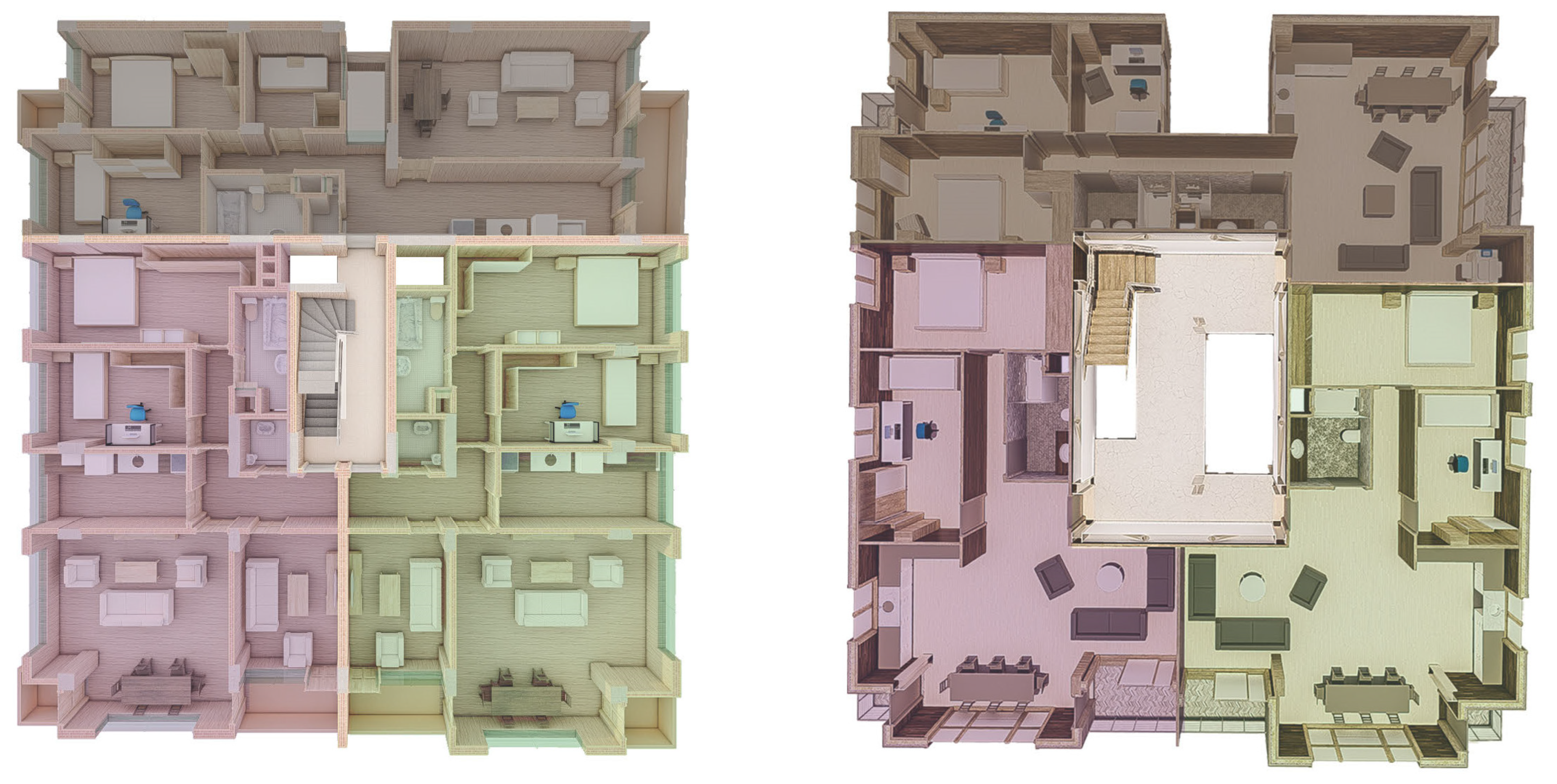
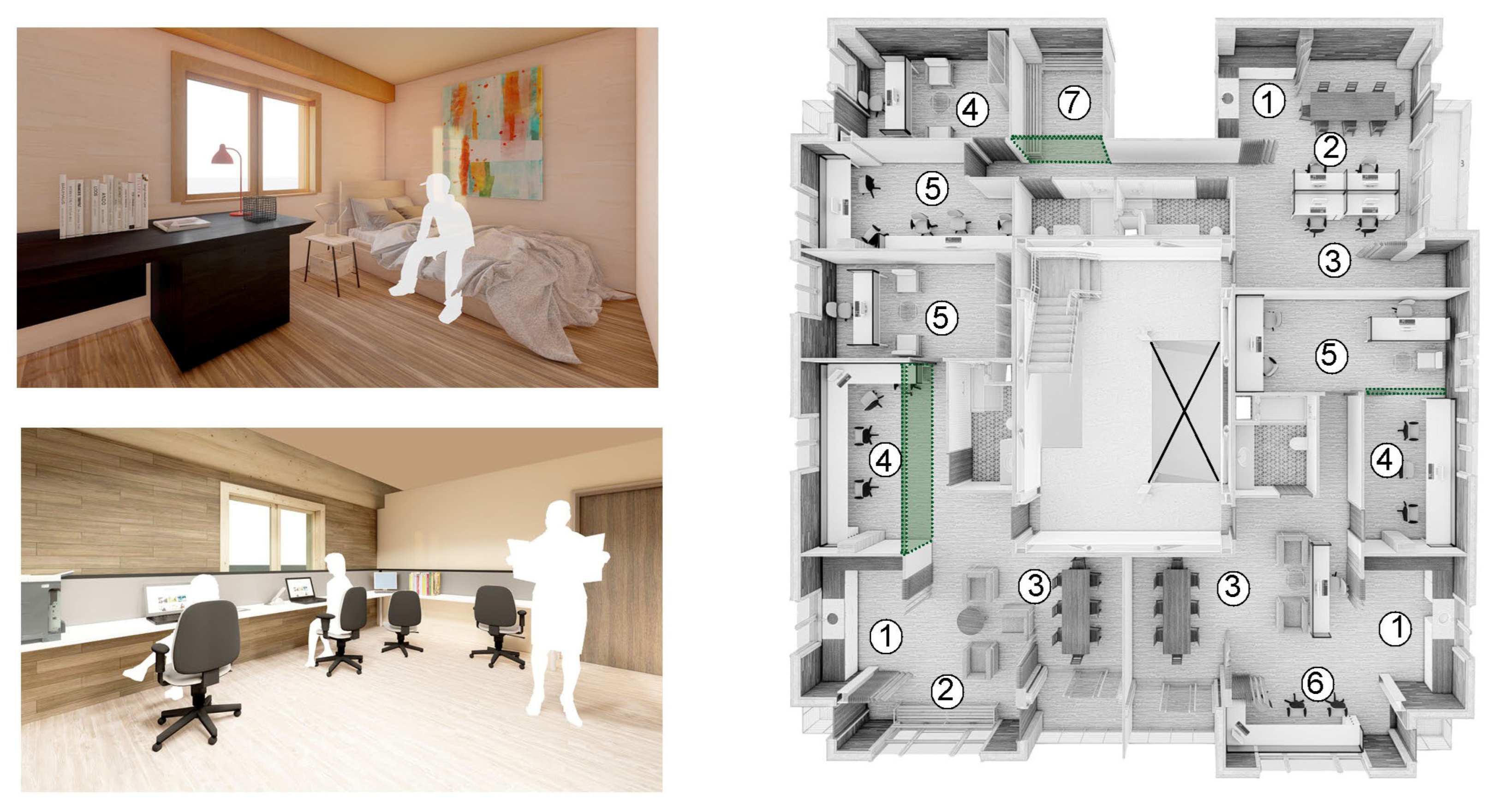
3.1. Building Structure and Layout Distributions

Although mid-rise CLT buildings have been implemented worldwide in areas with varied seismicity levels [51], had the new timber building been designed only with CLT panels, its architecture would have presented an important setback. Given the open nature of the ground and mezzanine floors, potential locations for CLT walls that must be continuous through the building height would not be enough to provide seismic resistance to the new timber building. In terms of architectural concerns, the addition of CLT walls would clash with the idea of open frames, which were required in the ground and mezzanine floors for commercial functions. Although modifications to the building’s architecture were on the table from the beginning, maintaining the original building typology as much as possible was one of the design priorities. For this reason, the addition of RC shear walls to these two floors was ruled out, as it also raised structural concerns. Adding shear walls to the lower floors means creating a RC podium structure, which is characterized for having a larger stiffness than that of the upper floors—built only with CLT walls and floors. Consequently, an important number of connections would be required to transfer large shear forces between the RC podium and the CLT structure. Furthermore, the idea of disassembling and reusing a RC podium structure poses a great deal of challenge to its design and construction. Even if prefabricated, such RC components must still be connected by casting them on site, increasing the carbon footprint of the whole system.
Alternatively, the option of a combining CLT floors and GLT braced-frames offered the possibility of a building design strongly resembling the original architecture of the RC building. In addition, a structural system composed entirely of linear structural elements—columns, beams, and braces—offered more design options for disassembly and reuse. Unfortunately, due to high seismicity of the chosen building location, segmented CLT shear walls constructed with platform-type and GLT bracing systems were disregarded due to their overall lack of ductility. Further limitations to the building height were 19.5 m (65 feet) and 20 m, as described in [52,53] for high level seismic zones, respectively. The latest Turkish Building Earthquake Code (2018), instead, establishes a 10.5 m height limitation corresponding to building height class 7 for timber lateral-force resisting systems in seismically active regions [54]. Thus, the team opted for using steel bracings as special concentrically braced frames (SCBF) with the building height class 4 resulting in a maximum of 42 m height to provide seismic resistance to the timber structure. In addition to GLT columns in timber frames, steel columns are required in balconies due to moment transmitting rigid connections.
The hybrid timber–steel solution is not only cheaper than using only a CLT structure but also facilitates the redesign of the building and improves the existing spatial distribution (Figure 3). Since there are 21 apartments in the building, the current Turkish Building Code demands to install at least 2 elevators [55]. This rule demanded freeing more space in the core of the existing plan layout, which originally had only one elevator. Such demand for space forced a redesign of the staircase and the position of the original elevator and adjustments of the structural axes of the core, which were defined at 6.95 m, leaving enough space for the braces (5.60 m) and for the opening leading to corridors (1.35 m), which in turn allowed access to the apartments.
For the design of the floors, three options were evaluated: a CLT + RC composite floor, a CLT floor and a ribbed slab, and one composed of CLT panels and GLT rib beams. The last flooring system with 10 cm thick CLT panels and 16 × 32 cm GLT rib beams at 100 cm was found optimal for reducing both the carbon footprint and total mass of the floor, as well as increasing detachability [56]. Despite its depth, the ribbed slab fits well within the 3.10 m floor height.
The redesign process of the 9-story RC moment frame building as hybrid timber–steel building structure is based on the following considerations:
  • The foundation and basement (underground) remain in RC;
  • The ground floor is considered commercial area;
  • The mezzanine floor is considered office area, yet live load is assumed equal to residential floors;
  • Seven floors are considered as residential areas;
  • Vertical force resisting system is designed in timber;
  • Lateral force resisting system is designed as steel concentrically braced frames;
  • Fire design strategies are considered.

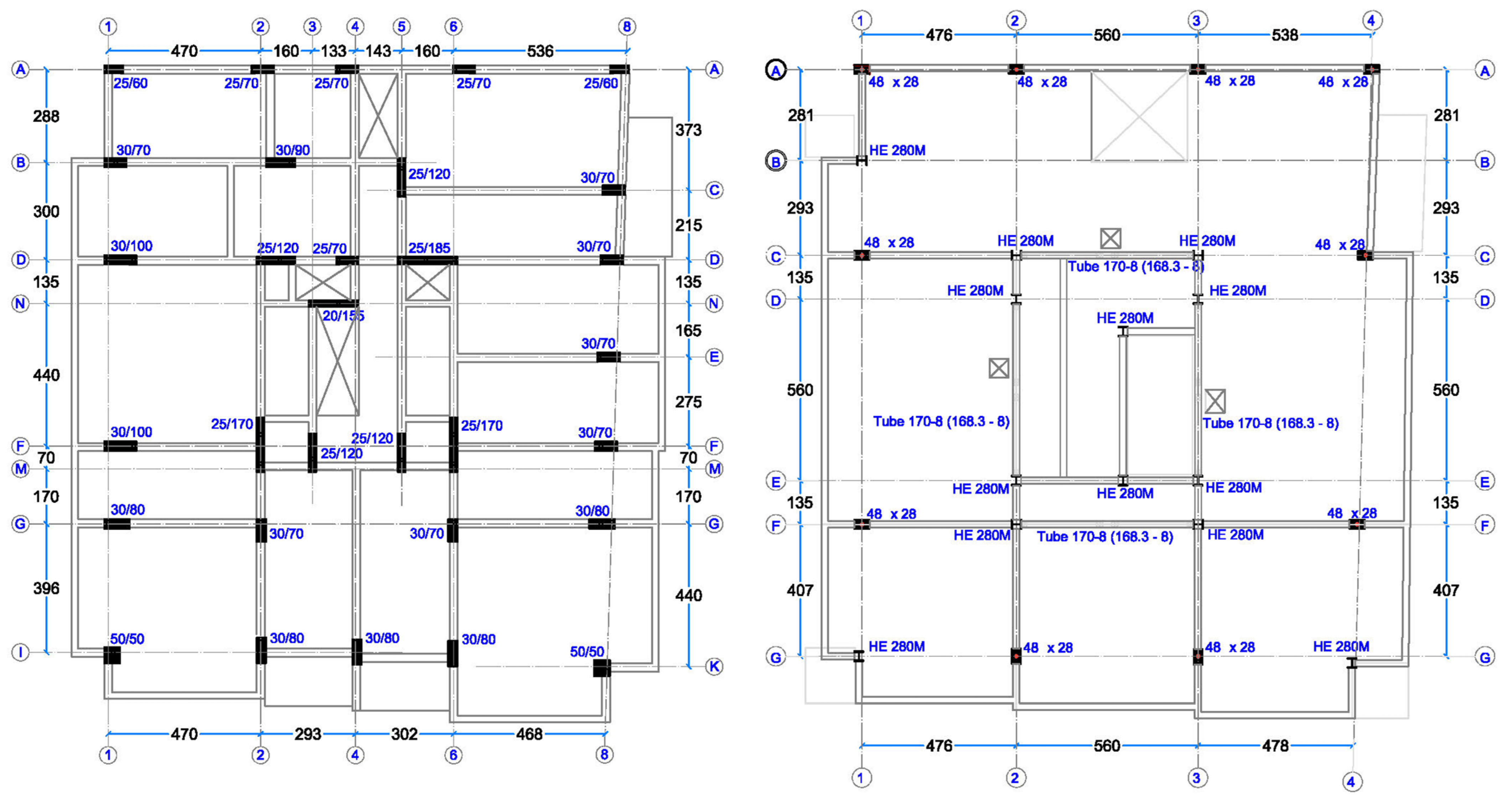
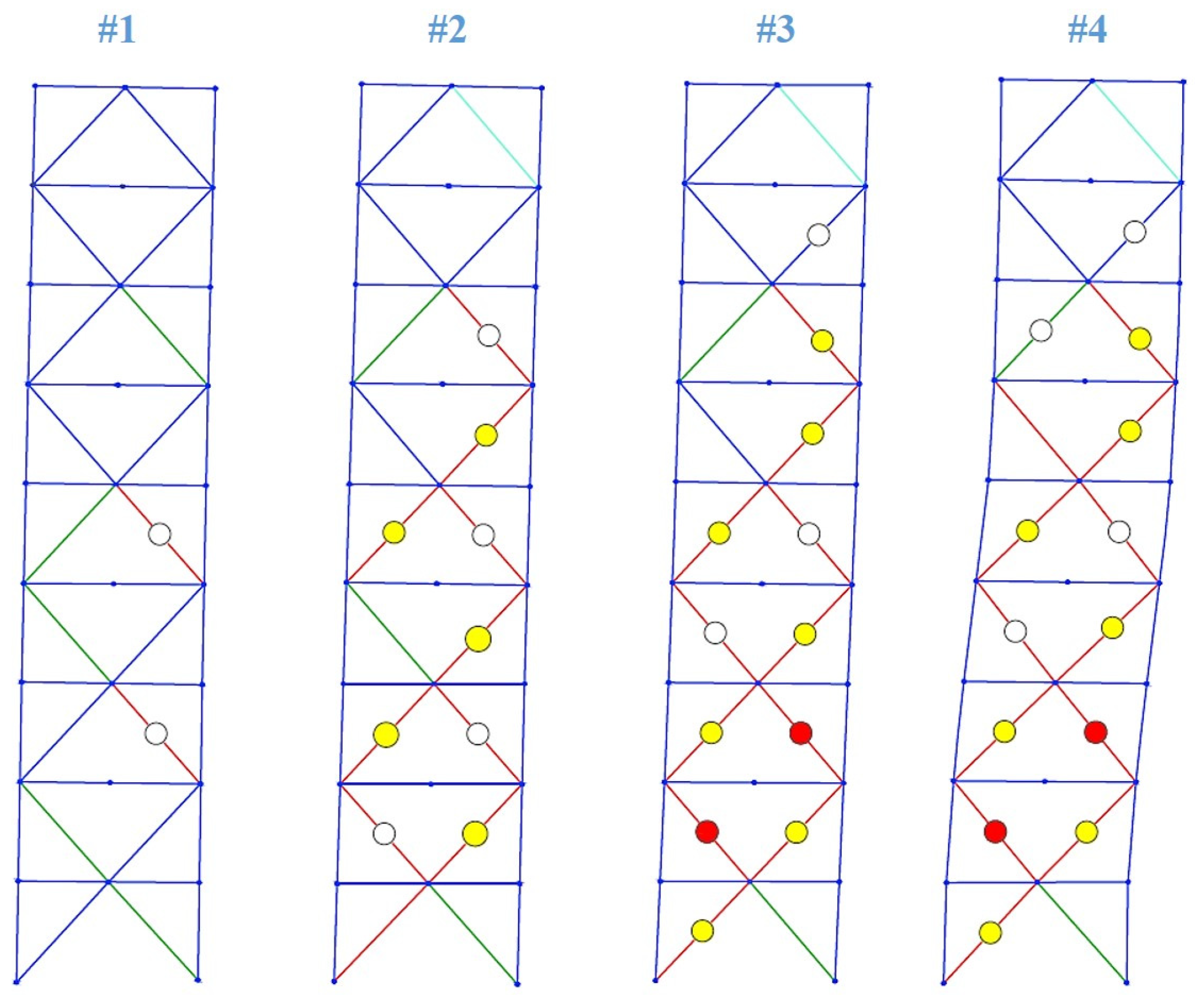
3.1.1. Vertical-Force Resistant System

The timber structure was designed according to TS EN 1995 [57], considering gravity loading resulting from dead loads of floors and roof being 3.7 kN/m2 and 2 kN/m2—compared with RC building being 5.6 kN/m2 and 3 kN/m2—respectively. Although live loads are identical due to the same functional usage, dead loads are significantly lower for timber structure because of the low weight of engineered wood products. For floors, CLT panels were 3-ply 10 cm thick with C24 class—pine providing in-plane capacity providing the diaphragm action and out-of-plane capacity determined by one-way slab behavior—matching economic design with a low carbon footprint. GLT column sections with GL28h class–pine change cross-sections every 3 stories as 28 × 48 cm, 28 × 36 cm, and 28 × 24 cm, respectively. Only one section of 20 × 60 cm GLT beams is used for simplicity of delivery and consistent site applications. The story height is 3.1 m, with a net story height equal to 2.6 m. For in-plane actions, CLT floor–GLT beam and horizontal CLT panel-to-panel joints are connected via using fully threaded self-tapping screws with 45-degree inclination to provide stiffer connection.

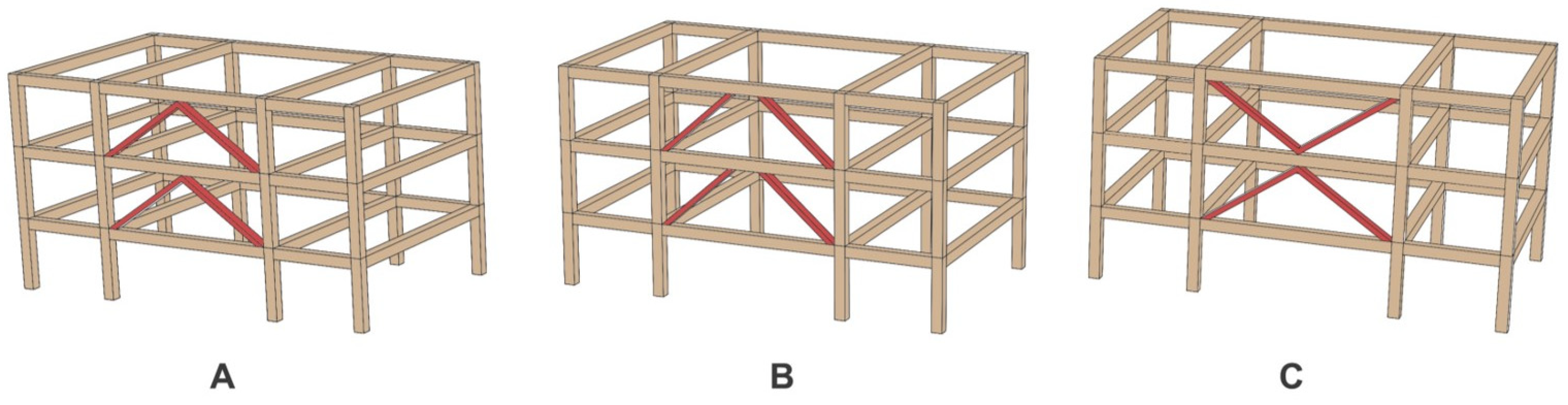
3.1.2. Seismic-Force Resistant System of the Hybrid Timber–Steel Building

For the lateral force-resisting system, seismic design forces almost double wind loads and thus control the design. As highly ductile steel structural systems, SCBFs are expected to dissipate earthquake energy input with the plastic deformations in braces through yielding and buckling. In contrast, consistent with capacity design philosophy, the structural members other than bracings are expected to remain elastic. The design of SCBF elements (Table 1) is conducted according to the capacity–design approach in Turkish Building Earthquake Code [54], similar to the requirements stipulated in AISC 341-16 [58]. Seismic design parameters for the target response spectrum were R = 5 (response modification factor), D = 2 (overstrength factor), I = 1 (importance factor), SD1 = 0.56 g, and SDS = 1.18 g, chosen for the local soil class of ZD from the seismic hazard map of Turkey [59]. Two SCBFs are placed for each direction at the core of building (Figure 4). The braces are symmetrically placed on the plan layout. The lateral force method was applied since the total height of the new building was 27.9 m. Following the upper limit defined by ASCE 7 [52], T1 = 0.83 s was considered in the design. Thus, the seismic base shear for a concentric braced frame is calculated as 751 kN.
For the lateral-force resistant system, the use of eccentric steel-braced frames (Figure 5B) was not considered because of the complexity of the link beam design in addition to high cost of connections due to the extensive welding labor. Therefore, structural analyses were carried out on concentric steel-braced frame configurations. To begin with, SCBFs were proposed as the inverted-V configuration known as chevron. However, given the ~60 cm depth of the steel girders, this configuration would not allow any opening underneath for doors (Figure 5A). Since the use of openings on the planes of the braced frames were finally ruled out, SCBFs with the split-X configuration (Figure 5C) were proposed instead, as they entailed a reduction of both the girders’ depth and beam section, resulting in a lower carbon footprint. As a result, the architecture of the floor plans had to be redesigned to avoid door openings on the brace locations, which led to modifications in the overall plan layouts.

3.1.3. Fire Resistant Design

Under the fire safety regulation of Turkey [60] and TS EN 1995-2 [61], and considering that the total building height is less than 30 m, possible fire protection strategies were (1) using fire sprinklers, providing protection for 60 min; (2) increasing cross-sections, providing protection for 90 min; and (3) using additional fire protection layers such as gypsum boards, providing protection for 90 min. Although, from a carbon reduction perspective, the obvious choice is a strategy that generates less CO2, each solution presented varied advantages. For example, using sprinklers implied that no additional fire protection layer was required for the timber sections. Leaving the timber sections untouched was deemed to be visually more attractive for the occupants. The shortcomings of this system were its higher cost and potentially increased carbon footprint due to production and installation of high-tech equipment. Although exposing the timber elements—rather than covering them—seemed to be more in-line with raising awareness of the use of timber in building construction, using a passive fire protection system provided by gypsum boards was preferred. Increasing the cross sections entailed an increase in the carbon footprint.
Escape routes in the core of the building nonetheless need extra fire resistance provided by sprinklers, gypsum boards, or fire-resistant paintings. Therefore, additional protection layers of gypsum boards are required for GLT columns and beams and CLT floor panels. GLT columns and steel members of SCBF in escape routes are painted with fire-retardant paint and secondary walls between fire stairs and apartments are covered with gypsum board panels in both sides. To ensure extra fire resistance of steel columns in the corners, some of balconies were made smaller to keep steel columns inside of the building.

3.2. Envelope, Finishing, and Building Components

Following the original ratio, each apartment is designed with layout areas of 85, 88, and 92 m2, respectively, and with varied number of rooms to meet different occupation demands. The living room and kitchen are designed as open spaces and kept as large as possible for supporting changing demands and provide flexibility. However, to match this flexibility of use, all components of the building must be designed following disassembly principles. Within the overall goal of reducing carbon footprint, design for disassembly is based on the following key design principles:
  • Maximizing the use of standard components for increasing potential for disassembly;
  • Minimizing energy consumption by reducing post-production of components (e.g., avoiding in situ modifications and/or cutting-offs);
  • Minimizing waste generation by adjusting design demands to standard components.

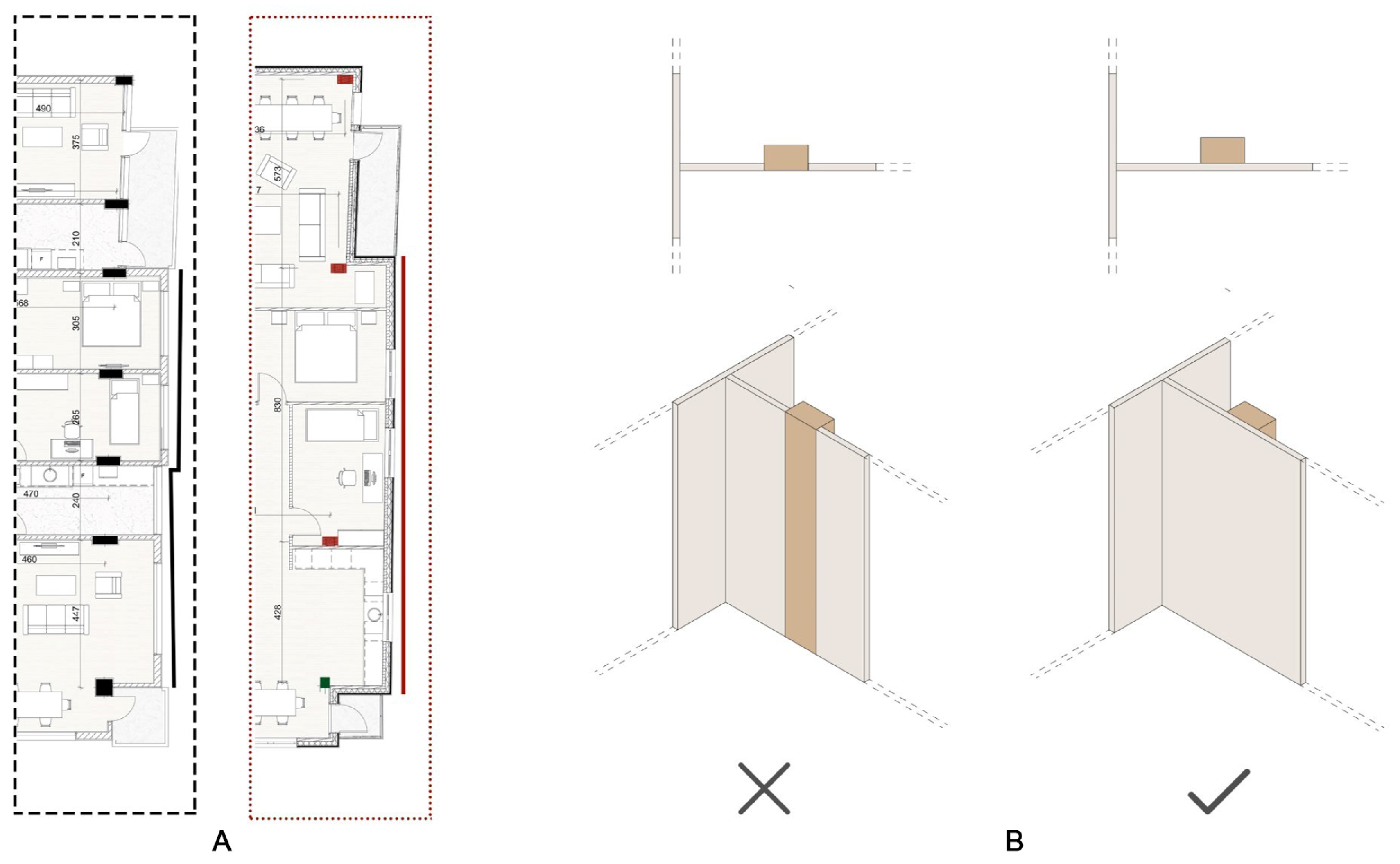
3.2.1. CLT Envelope and Partition Walls

In the original building, the east façade presented a staggered layout. This side was turned to a straight line in the timber building (Figure 6A) to reduce the amount of scrap and small pieces of CLT panels and the required electrical power to cut them in different sizes. Whenever possible, CLT wall panels of 5 m length were used for both easy transportation and increasing reuse potential in future projects. However, since the rest of the layout was kept in accordance with the original RC building plan, not all 5 m panels could fit as is in the new layout. This indicates that a grid system should be considered from the beginning in order to achieve a full use of standard panels. Yet in this case, those non-standard wall panels were designed to fit round numbers, e.g., 6 m, 5.50 m, or 5.30 m, so they still have a high potential for reuse. All CLT wall panels are 8 cm thick with 3-ply to provide standard sizes for use and reuse. When used for exterior walls, CLT panels were placed outside the GLT columns, instead of between them, to minimize cuttings and thus save energy. For the same reason, panels are connected to the external side of the beams. For the partition walls, panels were placed in front of the GLT columns (Figure 6B). This decision also allows redesigning the interior layout to meet users’ future needs such as changing from office to residential building or vice versa. Finally, to be consistent with the use of standard panels, ceilings were covered with 18 mm gypsum boards. Even though exposed beams are easy to access for the building’s maintenance during occupation, this option would have required cutting the panels in irregular patterns for them to match the irregular geometry of the interior walls. This not only increases energy consumption in both the production and fabrication processes but also produces customized CLT panels that may be difficult to adapt for a different project, thus reducing their potential for disassembly.

3.2.2. Openings and Building Components

Another way to reduce embodied carbon from the production process is by reducing the number of doors leading to the balconies, which were two per apartment in the original building. In addition, door and window sizes are standard, except for the windows in the living room, which were designed larger for increasing daylighting gains. Instead of the existing PVC frames, timber frames were chosen for the windows of the redesigned residential building. Carbon footprint reduction aside, the use of timber framed windows has several advantages compared to PVC ones. For instance, PVC windows can generate toxic materials during the production and end-of-life process, while timber windows have a longer lifespan than PVC windows [62]. All interior doors are made of timber, and most of them are placed in the corners of the rooms instead of in the middle of a wall. This allows for using one whole piece of CLT panel instead of small ones.
There are two exceptions to the overall use of timber: the exterior doors of the apartments and the balustrades used in balconies and stairs. Despite their larger carbon footprint, exterior doors are made of steel because they are widely available in Turkey, making them the most common type of door in residential buildings. Balustrades were designed with recyclable steel and stainless steel cable mesh, because at this scale, these components can be disassembled by means of detachable connections and reused in a different project. Therefore, embodied carbon resulting from the production process can be stored during the lifetime of the product. Finally, although a steel staircase was studied, the comparative low carbon footprint of the timber one made it the most suitable choice (Table 2).

4. Life Cycle Assessment of the Buildings

Following the standard procedures of life cycle assessment (LCA) of building components outlined in the Institution of Structural Engineers’ guide book [14], the embodied carbon emissions of a building are calculated by stages, considering the contribution of each material, as expressed in the following simplified relationship:
ECTOTAL = ECA13 + ECA45 + ECC,
where EC = embodied carbon, while A and C refer to the different stages. Product stage (A1–A3) is based on total EC of materials or components production including extraction, transportation, and manufacturing. Construction stage (A4–A5) comprises carbon emissions generated by transportation of materials to the construction site and construction activities. End-of-life stage (C) accounts for those carbon emissions produced when building material or component complete their service life. Following common practices in LCA, use stage (B) is not considered in this study, since it includes carbon footprint generated during occupation, which contributes in a comparatively small percentage to the total carbon emissions. Stage D, beyond the building life cycle, includes all CO2 emissions produced by reusing, recovering, and recycling building components. Despite its importance in the buildings’ potential for circularity, related carbon factors are not always available. For this reason, when available, the embodied carbon generated by stage D is noted separately, thus not included in the total building’s EC. Since reusing, recovering, and recycling are actually decreasing the carbon footprint, related factors are negative.
In order to compute the total EC of a stage for each material, the following general formula applies:
ECstage,i = Mi × CFi,
where stage refers to stages A, C, or D (when data are available), M is the mass in kg of the material (which, depending on the related carbon factor definition, can be replaced by the number of components (e.g., doors) or other measurement units (e.g., distance)), CF is the related carbon factor (usually expressed in kgCO2e/kg), and i is the related material, component, or process. The carbon factors of each material are obtained from the aforementioned guide and its recommended source, The Inventory of Carbon and Energy (ICE) database [63]. If the carbon factor is not available in those references, the Turkish Environmental Product Declaration (EPD) of the specific product is used. If there are no available data for a product in the EPD Turkey, international EPD documents are used. For timber, carbon sequestration is considered −1.64 kgCO2e per kg of timber [14].

4.1. Assumptions

To provide a comparative framework for the LCA being both consistent and coherent with the purposes of the studies, the following assumptions are made:
  • The original RC basement is kept the same in the new design. Because of the topography, three sides of the basement floor are underground; hence, it is very likely that this underground area will be still designed in RC even when the upper structural frame is timber. Since both basements are the same, their total carbon footprint would also be the same. Therefore, their carbon emissions are not considered in calculations.
  • For consistency, foundations are also kept the same in the new building. However, had a new foundation been designed, a reduction of embodied carbon can be expected [64]. This is because the reduced weight of a hybrid timber–steel structure, compared with that of the RC building, would require smaller foundations, reducing the amount of concrete and steel bars and thus bringing in a reduction in the overall carbon footprint.
  • The contribution of the embodied carbon of the insulation materials for the walls is not considered in the RC residential building. This is an effect of the old Turkish codes, which did not require buildings to have insulated facades. However, they were added in the timber building to assess their environmental impact in terms of carbon footprint and to serve as a design example of a timber building’s façade.
  • The embodied carbon produced by the production and use of elevators in the buildings is not considered. The reason is that in the existing building there is only one, whereas in the alternative building there are two, resulting from the application of current Turkish norms.

4.2. Results

According to the results displayed in Table 3, the total embodied carbon of the redesigned hybrid steel–timber residential building, without considering module D, is half of that produced by the original RC building. As expected, when considering only stages A1–A3, the RC building generates twice as much embodied carbon than the hybrid timber–steel building due to the high carbon emissions of reinforced concrete. On the other hand, the carbon footprint resulting from the stages C1–C4 is higher in the hybrid timber–steel building. This is because C3–C4 carbon factors of timber materials were considered with a default value, which is much higher than that of other materials (1.64 against 0.013 kgCO2e/kg). However, it should be noted that assuming this factor entails considering timber reaching the end of its service life as building material, i.e., that it will be incinerated. Since in this case the timber components are designed to be disassembled, the carbon sequestration factor applies, and, thus, the building almost reaches the zero-carbon emissions target.
In terms of distribution per building component (Figure 7), structural elements in the RC building (concrete and reinforcement bars) take up more than half of the total carbon footprint, whereas structural elements in the hybrid building account for about a third of the total—all this despite the fact that the hybrid building includes not only timber floor panels and frames but also steel elements in the SCBFs. Finishing components, such as plasterboards, insulations, claddings, parquet, ceramic tiles, and paint, comprise the largest contributor of embodied carbon in the hybrid building. The comparatively large increase can be partially explained by the fact that no insulation was considered in the RC building—as described in Section 4.1—whereas in the timber–steel hybrid building, these components accounted for 195,165 kgCO2e. Finally, the significant reduction in infills is the result of shifting from using brick infills to CLT partition walls.

5. Effects of Early Design Decisions on the Seismic and Functional Performance of the Building

5.1. Seismic Performance

Nonlinear static (pushover) analyses were conducted to compare the seismic response of both buildings. The modelling of the RC building and pushover analyses are thoroughly presented in [41]. For this reason, a brief summary is presented here:
  • Structure was modelled with and without infills;
  • Equivalent C18 and S220 materials were used for concrete and rebar, respectively;
  • Plastic hinges were defined at the end of beams and columns; shear hinges were applied to shear walls.
To evaluate its nonlinear seismic response, a numerical model of the hybrid timber–steel building consisting of a steel braced bay was developed as in [65]. Due to the symmetric locations of braced frames in the building core, a 2D numerical model is generated in Perform-3D [66], with a rigid leaning column representing the mass of the hybrid building. Hence, P-delta effects were considered. However, the influence of the GLT frames is not considered in the lateral response due to the use of simple shear tab connections. Based on the corresponding tributary areas, gravity loads were calculated and applied to the SCBF and the leaning column. Floor and roof masses were assumed to be lumped at the joints. Following the Turkish Seismic Code [54], the effective seismic mass is assumed equal to a third of the total live load. Steel girders and columns were considered to have a post-yield stiffness of 3% of their initial stiffness, and material nonlinearity was idealized by the concentrated plasticity technique employing P-M hinges. SCBF girders were composed of elastic beam components with moment releases at the ends and zero-length P-M plastic hinges at the center to check the effects of unbalanced forces. Since splices were arranged every two floors at 1.2 m above the top of the concrete slabs, two separate column cross-sections and corresponding zero-length P-M plastic hinges were included in the elastic segment and end regions, respectively. In the SCBFs, column bases were modelled as fixed, and lateral supports were defined at each joint to prevent out-of-plane movement. Roof displacement was selected to control the pushover, and floors were considered as rigid diaphragms.
Through modal analyses, the periods of the first two modes were determined as 0.98 and 0.21 s, with effective mass factors of 75% and 18%, respectively. The first mode period is larger than that of the RC building (Table 4). Although 0.98 s is also higher than the empirical upper limit period accepted for SCBFs as stated in ASCE 7 [52] the design of the hybrid timber–steel building is acceptable, as the seismic base shear demands are on the conservative side due to the lower seismic mass. Similarly, the reduction in shear capacity can be explained by the fact that steel structures are ductile and, compared with the RC building, there is a significant reduction in the building mass due to the use of fewer structural elements, which also have smaller sections (Figure 8). As a result, the lateral capacity of the hybrid timber–steel building is found to be adequate.
The analyses’ results of the RC Building are presented with and without infill walls, for consistency. The lateral capacity of the hybrid building is assumed to be equal in both directions as two identical SCBFs are placed at the core. Pushover curves and inter-story drift ratios of RC frames and SCBFs are presented in Figure 9. In the case of the RC building, the lack of infill walls increases inter-story drifts and top story displacements. The inter-story displacements show an increase in the second and third stories when the infill walls are removed. The increase in drift and the decrease in displacement responses are due to the fact that some ground floor columns display plastic behavior after removing the infill walls. However, in the case of the SCBF, buckling first appears in the braces of the third and fifth stories, under compression (Figure 10). Then, the load-carrying capacity continued to increase with a lower stiffness. At the peak load, a reduction in the lateral capacity occurred after the yielding of the multiple story braces at the second mechanism-leading stage. Therefore, the inelastic deformations are concentrated on low-to-mid story levels, and the lateral load-carrying capacities of SCBFs are gradually increased due to the steel frame action as a seismic back-up until the third mechanism-leading stage. Then, the capacity is reduced suddenly while plastic hinges representing post-buckling behavior are formed in the braces of second and third stories due to large shortening strains. In summary, although drift ratios are higher in the hybrid structure, this is due to the plastic deformation capacities of steel braces. Thus, SCBF’s lateral load-capacity is less than in the RC building, but its deformation capacity is much higher.

5.2. Functional Performance

A qualitative description focused on variation of architectural aspects, functional performance, and flexibility of spaces addresses the effects of the early design decisions for disassembly. Minor effects are observed at the level of building components. Shifting to timber staircases and window frames facilitates a reduction in carbon footprint, yet steel is chosen for balustrades to increase the potential for disassembly. In addition, the redesigned low-carbon timber window frames allow for enlargements bringing more sunlight into the rooms. Major effects are observed in the core and entrance areas of the hybrid building, which are enlarged thanks to the increased number of elevators and the consequent longer span between columns. The enlarged core provides a comfortable circulation area, meeting needs such as the placement of mailboxes and bicycle storage for the apartment residents.
The most significant changes are in the plan layouts of the apartments, which are three per floor. In the original RC building’s plan layout, apartments are 73, 90, and 99 m2 and contain five rooms. Because buildings components are not detachable, modifying the existing layout would require demolition and then renewal with new materials, thus increasing embodied carbon and building waste. Since rooms were designed for one function, flexibility for using flats for different purposes such as office space is limited. Although in the new residential building apartments are slightly smaller (85, 88, and 92 m2), the most striking feature is that they are designed as open plan to adapt to different uses (Figure 11). Thanks to detachable CLT panels, spaces can be modified by the users themselves. Moreover, the entire apartment can be reorganized as office space (Figure 12) by changing the function of each room (Table 5).

6. Conclusions and Future Research

In this study, an existing 9-story RC multi-story residential building is redesigned with CLT floors and GLT frames to investigate the effect of architectural and seismic design on embodied carbon reduction. The results of this evaluation (described next), are valid within consideration of the following assumptions:
  • Underground construction is not considered in these analyses. However, it should be noted that using CLT instead of RC can potentially reduce embodied carbon due to the comparatively reduced weight of CLT structures. This can result in the use of smaller foundations and thinner shear walls, requiring less concrete and RC bars and thus contributing to an overall reduction in embodied carbon.
  • Elevators were not considered in the total carbon footprint to avoid an unfair comparison between the existing building, which has one elevator, and the alternative design, which includes two.
  • Since the RC building was built according to the old building codes, no insulation was applied on the facade. Consequently, insulation materials were excluded from the computation of the RC building’s carbon footprint. In contrast, the timber building design incorporated insulation materials to highlight their impact on carbon emissions. It is worth noting that the addition of insulation materials in the RC building may result in a greater difference in embodied carbon between the two designs.
  • The existing building’s roof was inaccessible for a detailed evaluation. For consistency, the same timber roof structure was applied in both buildings.
According to the studies conducted in this study, under the aforementioned conditions, the following conclusions and further research can be elaborated:
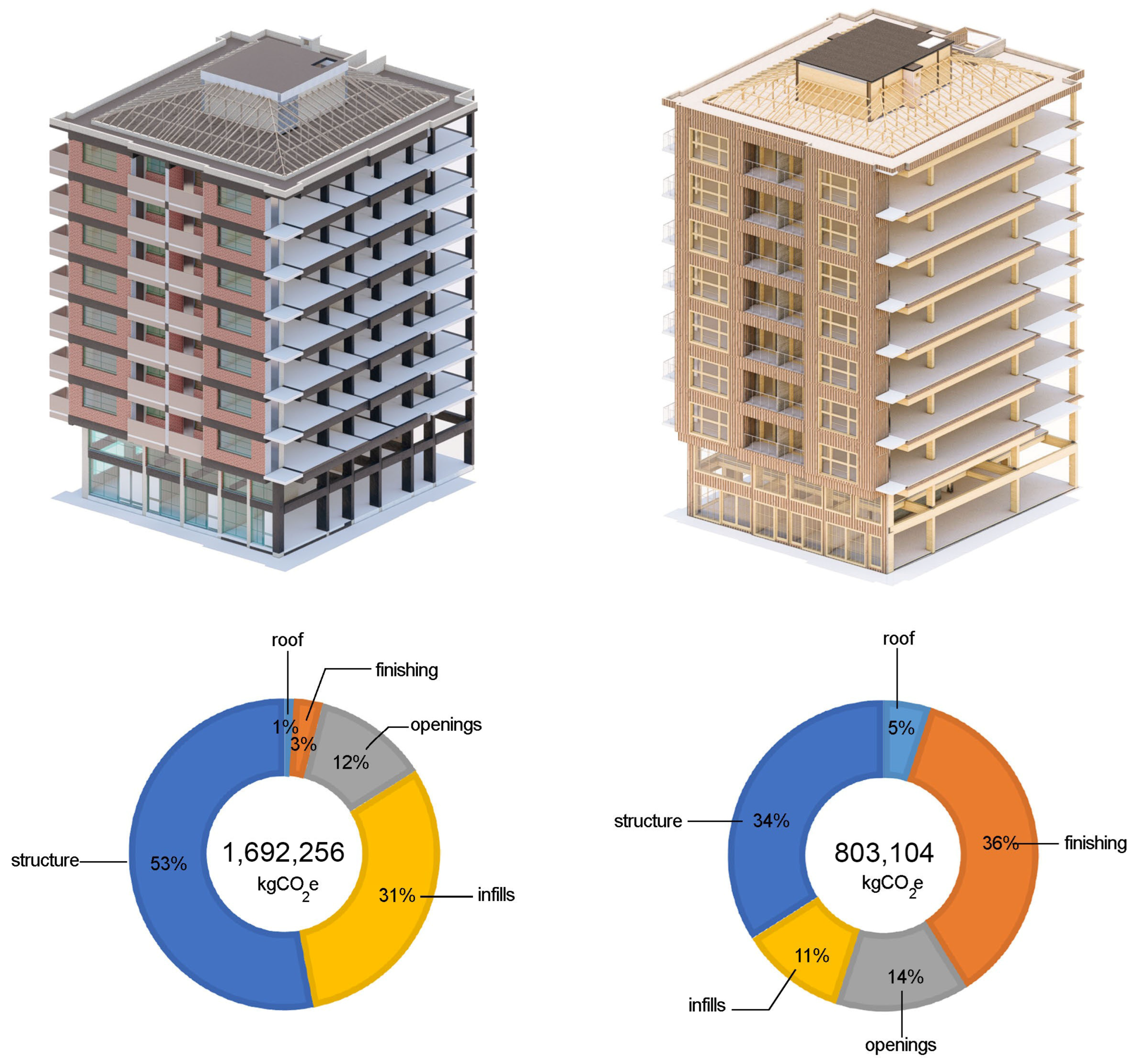
  • According to the results of the LCA, the RC residential building emits two times more carbon than the hybrid steel–timber residential building. When examined in terms of structure, the carbon footprint resulting from the production of concrete beams and columns is approximately six times higher than the production of timber columns and beams. This shows that if the building construction industry does not move away from reinforced concrete, there will be six times more CO2 emissions, leading to more extreme versions of global warming. As in similar studies [67], LCA is a reliable tool to evaluate and optimize architectural and structural engineering design choices to reduce the environmental impact of buildings.
  • The fundamental role of designing for disassembly becomes clear when considering that, if timber elements are reused, the hybrid building has almost no carbon footprint. From the lessons learned from the design process, the relevance of considering the carbon footprint in combination with the design decisions seems to be the key to introducing circular projects in seismic regions such as Italy, Greece, etc. This is because not all decisions are based on achieving the lower embodied carbon factor but rather on those that increase the potential for disassembly throughout the lifespan of the building.
  • Since the study focused on upgrading an existing building, a broader perspective is needed to validate the large reductions in embodied carbon when shifting from RC to timber buildings. For example, current building codes demand a larger number of elevators and skylights and the compulsory use of insulation, which cannot be simply compared to those resulting from past codes. Similarly, pre-existence entails several modifications performed by users through time, which are neglected in these studies for simplicity. However, users’ preferences and actions should be considered as part of the whole assessment for circularity potentials.
  • The complexity and entanglement of several disciplines when transitioning from demolition to disassembly seem to indicate that a holistic design approach is indeed required. In this regard, key aspects need to be researched. For instance, following usual practice when designing the lateral force-resisting system, GLT frames are assumed unable to transfer moment forces as they are connected with simple shear tab connectors, available in the market. However, these connections may behave semi-rigidly, and, thus, the contribution of the GLT frames to the seismic capacity of the hybrid building system could be also included.
  • Fire safety and protection is an import topic considering the relationship between fire performance levels and carbon footprint assessment. A timber design practice reported in [11] pointed out that increasing the sections will not largely affect the total amount of embodied carbon of a timber building.
  • Although the study is focused on applications within the Turkish context, its insights can be extended to regions where RC buildings are also common such as the Balkans, France, etc. as the hybrid timber–steel building design is based on international ones [54,57,59].

Author Contributions

Conceptualization, M.M.-B. and P.E.; Formal analysis, P.E. and Ö.A.Ş.; Funding acquisition, M.M.-B.; Investigation, M.M.-B., P.E., Ö.A.Ş. and G.N.A.; Methodology, M.M.-B., P.E. and Ö.A.Ş.; Project administration, M.M.-B.; Resources, G.N.A.; Software, Ö.A.Ş.; Supervision, M.M.-B.; Validation, M.M.-B. and Ö.A.Ş.; Visualization, G.N.A.; Writing—original draft, M.M.-B., P.E. and Ö.A.Ş.; Writing—review and editing, M.M.-B. All authors have read and agreed to the published version of the manuscript.

Funding

The work presented in this paper was funded by Yasar University Project Evaluation Commission (PDK) with the project BAP 109 “Building as a Material Bank: Applying Circular Economy Principles in the Design of Timber Residential Buildings in Turkey”.

Institutional Review Board Statement

Not applicable.

Informed Consent Statement

Not applicable.

Data Availability Statement

The data presented in this study are available on request from the corresponding author. The data are not publicly available due to privacy issues.

Conflicts of Interest

The authors declare no conflict of interest. The funders had no role in the design of the study; in the collection, analyses, or interpretation of data; in the writing of the manuscript; or in the decision to publish the results.

References

  1. Goldstein, N. Global Warming; Infobase Publishing: New York, NY, USA, 2009; ISBN 0-8160-6769-4. [Google Scholar]
  2. Heilbroner, R.L. Growth and Survival. Foreign Aff. 1972, 51, 139–153. [Google Scholar] [CrossRef]
  3. Bonneuil, C. The Shock of the Anthropocene: The Earth, History and Us; Verso Books: New York, NY, USA, 2016; ISBN 1-78478-082-0. [Google Scholar]
  4. Ahmed Ali, K.; Ahmad, M.I.; Yusup, Y. Issues, Impacts, and Mitigations of Carbon Dioxide Emissions in the Building Sector. Sustainability 2020, 12, 7427. [Google Scholar] [CrossRef]
  5. Atmaca, N.; Atmaca, A.; Özçetin, A.İ. The Impacts of Restoration and Reconstruction of a Heritage Building on Life Cycle Energy Consumption and Related Carbon Dioxide Emissions. Energy Build. 2021, 253, 111507. [Google Scholar] [CrossRef]
  6. Chou, J.-S.; Yeh, K.-C. Life Cycle Carbon Dioxide Emissions Simulation and Environmental Cost Analysis for Building Construction. J. Clean. Prod. 2015, 101, 137–147. [Google Scholar] [CrossRef]
  7. Paik, I.; Na, S. Comparison of Carbon Dioxide Emissions of the Ordinary Reinforced Concrete Slab and the Voided Slab System During the Construction Phase: A Case Study of a Residential Building in South Korea. Sustainability 2019, 11, 3571. [Google Scholar] [CrossRef]
  8. World Green Building Council Bringing Embodied Carbon Upfront: Coordinated Action for the Building and Construction Sector to Tackle Embodied Carbon; World Green Building Council Toronto: Toronto, ON, Canada, 2019.
  9. Jayawardana, A.S.; Perera, N.G.R.; Perera, L.A.S.R. “Cradle to Gate” Assessment of Material Related Embodied Carbon: A Design Stage Stratagem for Mid-Rise Housing in Sri Lanka. Energy Build. 2021, 230, 110542. [Google Scholar] [CrossRef]
  10. Rodrigues, V.; Martins, A.A.; Nunes, M.I.; Quintas, A.; Mata, T.M.; Caetano, N.S. LCA of Constructing an Industrial Building: Focus on Embodied Carbon and Energy. Energy Procedia 2018, 153, 420–425. [Google Scholar] [CrossRef]
  11. Hens, I.; Solnosky, R.; Brown, N.C. Design Space Exploration for Comparing Embodied Carbon in Tall Timber Structural Systems. Energy Build. 2021, 244, 110983. [Google Scholar] [CrossRef]
  12. Azari, R.; Abbasabadi, N. Energy & Buildings Embodied Energy of Buildings: A Review of Data, Methods, Challenges, and Research Trends. Energy Build. 2018, 168, 225–235. [Google Scholar] [CrossRef]
  13. Cabeza, L.F.; Boquera, L.; Chàfer, M.; Vérez, D. Embodied Energy and Embodied Carbon of Structural Building Materials: Worldwide Progress and Barriers through Literature Map Analysis. Energy Build. 2021, 231, 110612. [Google Scholar] [CrossRef]
  14. Gibbons, O.P.; Orr, J.J. How to Calculate Embodied Carbon; The Institution of Structural Engineers: London, UK, 2020; ISBN 978-1-906335-47-2. [Google Scholar]
  15. Ng, W.Y.; Chau, C.K. New Life of the Building Materials-Recycle, Reuse and Recovery. Energy Procedia 2015, 75, 2884–2891. [Google Scholar] [CrossRef]
  16. Hawkins, W.; Cooper, S.; Allen, S.; Roynon, J.; Ibell, T. Embodied Carbon Assessment Using a Dynamic Climate Model: Case-Study Comparison of a Concrete, Steel and Timber Building Structure. Structures 2021, 33, 90–98. [Google Scholar] [CrossRef]
  17. Sariatli, F. Linear Economy Versus Circular Economy: A Comparative and Analyzer Study for Optimization of Economy for Sustainability. Visegr. J. Bioeconomy Sustain. Dev. 2017, 6, 31–34. [Google Scholar] [CrossRef]
  18. Michelini, G.; Moraes, R.N.; Cunha, R.N.; Costa, J.M.H.; Ometto, A.R. From Linear to Circular Economy: PSS Conducting the Transition. Procedia CIRP 2017, 64, 2–6. [Google Scholar] [CrossRef]
  19. Bates, A.; Kelly, P.; Schoonhoven, J.; Riis-Tolman, T.; Snabe, K. The Business Case for Circular Buildings: Exploring the Economic, Environmental and Social Value; World Business Council for Sustainable Development: Geneva, Switzerland, 2021; p. 49. [Google Scholar]
  20. Ellen Macarthur Foundation Completing the Picture: How the Circular Economy Tackles Climate Change 2021. Available online: https://ellenmacarthurfoundation.org/completing-the-picture (accessed on 3 March 2022).
  21. Kirchherr, J.; Reike, D.; Hekkert, M. Conceptualizing the Circular Economy: An Analysis of 114 Definitions. Resour. Conserv. Recycl. 2017, 127, 221–232. [Google Scholar] [CrossRef]
  22. Akinade, O.O.; Oyedele, L.O.; Ajayi, S.O.; Bilal, M.; Alaka, H.A.; Owolabi, H.A.; Bello, S.A.; Jaiyeoba, B.E.; Kadiri, K.O. Design for Deconstruction (DfD): Critical Success Factors for Diverting End-of-Life Waste from Landfills. Waste Manag. 2017, 60, 3–13. [Google Scholar] [CrossRef]
  23. Rios, F.C.; Chong, W.K.; Grau, D. Design for Disassembly and Deconstruction—Challenges and Opportunities. Procedia Eng. 2015, 118, 1296–1304. [Google Scholar] [CrossRef]
  24. Lupíšek, A.; Vaculíková, M.; Mancík, S.; Hodková, J.; Ržika, J. Design Strategies for Low Embodied Carbon and Low Embodied Energy Buildings: Principles and Examples. Energy Procedia 2015, 83, 147–156. [Google Scholar] [CrossRef]
  25. Victoria, M.F.; Perera, S. Parametric Embodied Carbon Prediction Model for Early Stage Estimating. Energy Build. 2018, 168, 106–119. [Google Scholar] [CrossRef]
  26. Grover, R. Towards Zero Carbon Buildings Reducing the Embodied Carbon Footprint of a Construction. Master’s Thesis, Delft University of Technology, Delft, The Netherlands, 2020. [Google Scholar]
  27. Low Carbon Turkey Technical Assistance for Developed Analytical Basis for Formulating Strategies and Actions towards Low Carbon Development: Activity 1.1.1 Review and Analysis of the Status of the Climate Related Strategies, Policies, Plans, and Legislation (Status Report); Hulla & Co Human Dynamics KG: Köln, Germany, 2017.
  28. GIZ Turkish Building Sector Energy Efficiency Technology Atlas; 2018. GIZ-Deutsche Gesellschaft für Internationale Zusammenarbeit (GIZ) GmbH. Available online: https://www.giz.de/de/downloads/giz2019-en-turkish-building-sector.pdf (accessed on 3 March 2022).
  29. Low Carbon Turkey Technical Assistance for Developed Analytical Basis for Formulating Strategies and Actions Towards Low Carbon Development: Activity 1.1.2 Identification of the Sectoral Development Policies Intended to Meet the GHG Emissions Reduction Targets (Demand Stat); Hulla & Co Human Dynamics KG: Köln, Germany, 2018.
  30. Ahmetoğlu, S.; Tanık, A. Management of Carbon Footprint and Determination of GHG Emission Sources in Construction Sector. Int. J. Environ. Geoinform. 2020, 7, 191–204. [Google Scholar] [CrossRef]
  31. Neelis, M.; Geres, R.; Mert, E.; Döğerlioğlu, Ö. Roadmap for the Consideration of Establishment and Operation of a Greenhouse Gas Emissions Trading System in Turkey; Hulla & Co Human Dynamics KG: Köln, Germany, 2016. [Google Scholar]
  32. Schenk, M.; Hübner, C.; Cabrero, J.M. Cross-Laminated Timber: A Survey on Design Methods and Concepts in Practice. CivilEng 2022, 3, 610–629. [Google Scholar] [CrossRef]
  33. Santana-Sosa, A.; Kovacic, I. Barriers, Opportunities and Recommendations to Enhance the Adoption of Timber within Multi-Storey Buildings in Austria. Buildings 2022, 12, 1416. [Google Scholar] [CrossRef]
  34. Araya, R.; Guillaumet, A.; do Valle, Â.; Duque, M.D.; Gonzalez, G.; Cabrero, J.M.; De León, E.; Castro, F.; Gutierrez, C.; Negrão, J.; et al. Development of Sustainable Timber Construction in Ibero-America: State of the Art in the Region and Identification of Current International Gaps in the Construction Industry. Sustainability 2022, 14, 1170. [Google Scholar] [CrossRef]
  35. Follesa, M.; Fragiacomo, M.; Casagrande, D.; Tomasi, R.; Piazza, M.; Vassallo, D.; Canetti, D.; Rossi, S. The New Provisions for the Seismic Design of Timber Buildings in Europe. Eng. Struct. 2018, 168, 736–747. [Google Scholar] [CrossRef]
  36. Xia, Z.Y.; van de Kuilen, J.W.G. Numerical Analysis of Tall CLT-Concrete Buildings with Mechanical Connections. Eur. J. Wood Wood Prod. 2016, 74, 487–489. [Google Scholar] [CrossRef]
  37. Salvadori, V. Worldwide Structural Survey of 197 Multi-Storey Timber-Based Buildings From 5 to 24 Storeys. In Proceedings of the WCTE2020, Santiago, Chile, 24–27 August 2020. [Google Scholar]
  38. Gurbuz, T.; Cengiz, A.; Kolemenoglu, S.; Demir, C.; Ilki, A. Damages and Failures of Structures in İzmir (Turkey) during the October 30, 2020 Aegean Sea Earthquake. J. Earthq. Eng. 2022, 27, 1–42. [Google Scholar] [CrossRef]
  39. Yakut, A.; Sucuoğlu, H.; Binici, B.; Canbay, E.; Donmez, C.; İlki, A.; Caner, A.; Celik, O.C.; Ay, B.Ö. Performance of Structures in İzmir after the Samos Island Earthquake. Bull. Earthq. Eng. 2022, 20, 7793–7818. [Google Scholar] [CrossRef]
  40. Özacar, A.A.; Gülerce, Z.; Sopacı, E.; Askan Gündoğan, A. The October 30, 2020 Izmir-Seferihisar Offshore (Samos) Earthquake (MW= 6.6) Reconnaisance Observations and Findings. 2020. Available online: https://eerc.metu.edu.tr/en/system/files/documents/Izmir%20Earthquake%20Report.pdf (accessed on 3 March 2022).
  41. Morales-Beltran, M.; Durmuşlar, F.; Kızılörenli, E. User-Oriented Architectural Design of Separated Infill Walls to Prevent Soft Ground Story in Reinforced Concrete Low-Rise Buildings. J. Archit. Eng. 2021, 27, 04021018. [Google Scholar] [CrossRef]
  42. Fawzy, S.; Osman, A.I.; Doran, J.; Rooney, D.W. Strategies for Mitigation of Climate Change: A Review. Environ. Chem. Lett. 2020, 18, 2069–2094. [Google Scholar] [CrossRef]
  43. Bellona Circularity in Concrete & Cement. Available online: https://bellona.org/news/climate-change/2022-02-circularity-in-cement-and-concrete (accessed on 16 August 2022).
  44. Bertino, G.; Kisser, J.; Zeilinger, J.; Langergraber, G.; Fischer, T.; Österreicher, D. Fundamentals of Building Deconstruction as a Circular Economy Strategy for the Reuse of Construction Materials. Appl. Sci. 2021, 11, 939. [Google Scholar] [CrossRef]
  45. Kaufmann, H.; Krötsch, S.; Winter, S. Manual of Multi-Storey Timber Construction; Detail Business Information GmbH: Munich, Germany, 2018; ISBN 9783955533946. [Google Scholar]
  46. Blaß, H.J.; Sandhaas, C. Timber Engnering Principles for Design for Safety; KIT Scientific Publishing: Karlsruhe, Germany, 2017; ISBN 9783731506737. [Google Scholar]
  47. Herzog, T.; Natterer, J.; Schweitzer, R.; Volz, M.; Winter, W. Timber Construction Manual; Birkhäuser: Basel, Switzerland, 2004; ISBN 9783764369842. [Google Scholar]
  48. Younis, A.; Dodoo, A. Cross-Laminated Timber for Building Construction: A Life-Cycle-Assessment Overview. J. Build. Eng. 2022, 52, 104482. [Google Scholar] [CrossRef]
  49. Aydin, S.; Sisman, O.A.; Ilki, A.; Lus, H.; Ceccotti, A. Comparison of a Mid-Rise Reinforced Concrete and a Cross-Laminated Timber Building Designed for Minimum Seismic Damage. In Proceedings of the SECED2019, Washington, DC, USA, 7–9 November 2019. [Google Scholar]
  50. Crowther, P. Design for Disassembly—Themes and Principles. Environ. Des. Guide 2005, 2, 1–7. [Google Scholar]
  51. Tannert, T.; Follesa, M.; Fragiacomo, M.; Gonzalez, P.; Isoda, H.; Moroder, D.; Xiong, H.; van de Lindt, J. Seismic Design of Cross-Laminated Timber Buildings. Wood Fiber Sci. 2018, 50, 3–26. [Google Scholar] [CrossRef]
  52. ASCE/SEI 7-22; Minimum Design Loads and Associated Criteria for Buildings and Other Structures. American Society of Civil Engineers: Reston, VA, USA, 2021.
  53. National Building Code of Canada; Associate Committee on the National Building Code, National Research Council of Canada (NRCC): Ottawa, ON, Canada, 2020.
  54. Turkish Building Earthquake Code 2018; Specifications for Buildings to Be Built in Seismic Areas; Disaster and Emergency Management Presidency, Ministry of Public Works and Settlement Ankara: Ankara, Turkey, 2018.
  55. Turkish Building Code 2017; Ministry of Public Works and Settlement: Ankara, Turkey, 2017.
  56. Morales-Beltran, M.; Şişman, Ö.A.; Engür, P.; Şeker, O.; Aykar, G.N. Shifting from Demolition to Disassembly: A Hybrid Timber-Steel Multistory Residential Building for Circular Design. In Proceedings of the 7th WMCAUS 2022, Prague, Czech Republic, 5 September 2022; p. 10. [Google Scholar]
  57. EN 1995-1-1; Eurocode 5: Design of Timber Structures—Part 1-1: General—Common Rules and Rules for Buildings. CEN: Bruxelles, Belgium, 2004.
  58. AISC. Seismic Provisions for Structural Steel Buildings; AISC 341-16; American Institute of Steel Construction: Chicago, IL, USA, 2016. [Google Scholar]
  59. Turkish Seismic Hazard Map 2020; Disaster and Emergency Management Presidency, Ministry of Public Works and Settlement Ankara: Ankara, Turkey, 2020.
  60. Regulation for Buildings’ Fire Safety 2021; Disaster and Emergency Management Presidency, Ministry of Public Works and Settlement Ankara: Ankara, Turkey, 2021.
  61. EN 1995-1-2; Eurocode 5: Design of Timber Structures—Part 1-2: General—Structural Fire Design. CEN: Bruxelles, Belgium, 2004.
  62. Çalışkan, H. Industrial Wooden Window Production and Features 2022. Available online: https://www.youtube.com/watch?v=gQri2EbCczk. (accessed on 2 June 2022).
  63. Circular Ecology Embodied Carbon—The ICE Database. Available online: https://circularecology.com/embodied-carbon-footprint-database.html (accessed on 2 January 2022).
  64. Waugh Thistleton Architects. 100 Projects UK CLT; Waugh Thistleton Architects: London, UK, 2018. [Google Scholar]
  65. Şeker, O.; Şişman, Ö.A.; Akbaş, B. Evaluation of State-of-the-Art Capacity Design Approach to Seismic Design of Steel Concentrically Braced Frames. J. Fac. Eng. Archit. Gazi Univ. 2022, 37, 739–756. [Google Scholar]
  66. CSI. PERFORM-3D; Computers and Structures, Inc.: Berkeley, CA, USA, 2013. [Google Scholar]
  67. Dodoo, A.; Nguyen, T.; Dorn, M.; Olsson, A.; Bader, T.K. Exploring the Synergy between Structural Engineering Design Solutions and Life Cycle Carbon Footprint of Cross-Laminated Timber in Multi-Storey Buildings. Wood Mater. Sci. Eng. 2022, 17, 30–42. [Google Scholar] [CrossRef]
Figure 1. Seismic damage in buildings in Kahramanmaraş (left) and Antakya (right) [Photos by the authors].
Sustainability 15 07273 g001
Figure 2. The selected case-study displaying typical and ground floor plans (above and below images, respectively).
Sustainability 15 07273 g002
Figure 3. The layout of the core area in the original and redesigned buildings (above), and the corresponding modification of structural axes (below).
Sustainability 15 07273 g003
Figure 4. Vertical- and Seismic-force Resistant Structures.
Sustainability 15 07273 g004
Figure 5. The three options of braced frames: (A) concentric chevron, (B) eccentric inverted-V, and (C) concentric split-X.
Sustainability 15 07273 g005
Figure 6. (A) the ‘straightening’ of the east side of the building, and (B) the placing of the CLT panels as partition walls.
Sustainability 15 07273 g006
Figure 7. Carbon Footprint and distributions of the RC and Hybrid buildings.
Sustainability 15 07273 g007
Figure 8. Typical structural plans of RC (left) and Hybrid Timber–Steel (Right) buildings. The columns’ dimensions are indicated by, for example, 30/100, 48 × 28, and HE 280 M, which describe the dimensions of the RC, timber, and steel columns, respectively. Dimensions of the SCBF are indicated by the legend Tube.
Sustainability 15 07273 g008
Figure 9. Inter-story drifts (a) and pushover curves (b) of the RC building with infill and without infill walls and the hybrid building with the plastic mechanism of braces: first buckling (#1), multiple yielding (#2), post-buckling (#3) and final (#4).
Sustainability 15 07273 g009
Figure 10. Plastic mechanism-leading stages of SCBFs for pushover analyses: first buckling (#1), multiple yielding (#2), post-buckling (#3) and final (#4)(white: buckling, yellow: yielding, red: post-buckling).
Sustainability 15 07273 g010
Figure 11. Distribution of apartments per floor in the original (left) and new (right) building.
Sustainability 15 07273 g011
Figure 12. Transformation of a bedroom into an office space, and plan layout with indications of places suitable for functional changes; changes are given in Table 5.
Sustainability 15 07273 g012
Table 1. SCBF design specifications.
StoryS235 BracesS355 ColumnsS355 Girders
G–1Tube 180 × 8HE 280 MHE 180 B brace-intercepted girders
HE 200 B main girders
HE 200 M roof girder
2–3Tube 170 × 8HE 240 M
4–5Tube 170 × 6HE 180 M
6–7Tube 140 × 6HE 120 M
8Tube 115 × 4HE 100 M
Table 2. Carbon Footprint of Staircases (one story, factors from the ICE Database [63]).
Staircase TypeMaterial DistributionMass (kg)Carbon Factor (kgCO2e)Embodied Carbon (kgCO2e)Total Embodied Carbon (kgCO2e)
Hybrid Timber–SteelTimber Tread1370.49367.631,095
Steel Stringer1571.55243.35
Steel OnlySteel Tread3142.46772.44101,579
Steel Stringer1571.55243.35
Timber OnlyTimber Tread1370.49367.616,911
Timber Stringer2060.493101.51
Table 3. Distribution of Embodied Carbon per Stage.
StageCarbon Emissions (kgCO2e)
Reinforced ConcreteHybrid Timber–Steel
Products/Materials (A1–A3)1,345,225622,207
Transport/Construction (A4–A5)162,94624,290
End-of-life Disposal (C1–C4)244,0041,033,557
Carbon Sequestration−64,922−876,950
Total Embodied Carbon1,692,256803,104
Module D−64,922−139,590
Table 4. Pushover Parameters.
BuildingConfigurationT (s)Base Shear (kN)
RCWith infill walls0.627357
Without infill walls0.677282
Hybrid Timber–SteelSCBF0.982500
Table 5. Changes in the layout of the apartments by function (complementary to Figure 12).
Number in Plan (Figure 12)ResidentialOffice
1Open kitchenKitchenette
2Dining roomWaiting area
3Living roomMeeting room
4Bedroom Office room
5Suite bedroomPrivate office
6Dining roomWorking area
7Studio roomWaiting area
Disclaimer/Publisher’s Note: The statements, opinions and data contained in all publications are solely those of the individual author(s) and contributor(s) and not of MDPI and/or the editor(s). MDPI and/or the editor(s) disclaim responsibility for any injury to people or property resulting from any ideas, methods, instructions or products referred to in the content.

