Article

Experimental Study on the Mechanical and Acoustic Characteristics of Cemented Backfill with Unclassified Tailings at Different Curing Ages under Uniaxial Compression

1
College of Resources and Environmental Engineering, Jiangxi University of Science and Technology, Ganzhou 341000, China
2
Key Laboratory of Mining Engineering of Jiangxi Province, Jiangxi University of Science and Technology, Ganzhou 341000, China
3
Deep Vein Group Mine Intelligent Mining Technology Innovation Center of Ganzhou, Jiangxi University of Science and Technology, Ganzhou 341000, China
4
Xinyu Iron & Steel Group Co., Ltd., Xinyu 338000, China
5
Mechanical and Electronic Engineering Department, Gannan University of Science and Technology, Ganzhou 341000, China
*
Author to whom correspondence should be addressed.
Sustainability 2023, 15(9), 7177; https://doi.org/10.3390/su15097177
Submission received: 9 February 2023 / Revised: 19 March 2023 / Accepted: 21 April 2023 / Published: 25 April 2023

Abstract

:
In order to study the influence of the cement–tailing ratio and curing age on the mechanical properties of cemented backfill with unclassified tailings and improve the accuracy of the backfill monitoring method, the mechanical characteristics of the failure process of cemented backfill with unclassified tailings at different curing ages were studied using the acoustic emission and infrasound method. The results show that the peak strength and modulus of elasticity of backfill are positively correlated with the curing age. During the failure process of cemented backfill with unclassified tailings, the acoustic emission ringing count shows a “stabilizing–rising–falling–rising” trend, and the infrasonic ringing count will have a “multiple peak” phenomenon. The ib value of the acoustic emission signal generally increases with the extension of the curing age. The ib value of the infrasonic signal generally has a negative correlation with the increase of the curing age. When the ib value of the acoustic emission and infrasonic wave all start to decline in a jumping manner, this indicates that the backfill is about to be damaged. The dominant frequency ratio of acoustic emission signals (FAE) is distributed between 0–4 during the failure process, and the total number of FAE shows the phenomenon of “first decreasing and then increasing” with the curing age. The dominant frequency ratio of infrasonic signals (Fs) is distributed between 0–6. During the failure process of cemented backfill with unclassified tailings, the quantity ratio of class A and B of acoustic emission signals shows a gradually increasing trend, and the quantity ratio of class A and B of infrasonic signals shows a “decreasing–increasing–decreasing” trend, and the quantity ratio of class A and B of acoustic signals shows a sharp increase at the stage of entering the crack’s unstable growth stage.

1. Introduction

In recent years, with the increase of mineral demand and the decrease of shallow resources, mining activities have gradually developed and are followed by steep ground stress and other problems. In addition, the national requirements for safety and environmental protection are increasing, and more mines are using the filling mining method [1,2]. Backfill plays a role in supporting rock mass, controlling and reducing ground pressure activities, preventing surface subsidence, protecting surface materials, and improving the stress of pillars. However, as a multiphase composite material, backfill contains micro-cracks, micro-pores, bubbles, and other defects, which are extremely complex due to their mechanical properties and failure mechanisms and have distinct damage properties. How to accurately grasp the fracture development of backfill and predict the failure precursors of backfill is of great significance for the normal production and sustainable development of mines.
Acoustic emission signal technology and infrasound signal technology are important tools to study the propagation and evolution of cracks in materials. Acoustic emission signals and infrasound signals are the accompanying phenomena of strain energy released to the outside in the form of elastic waves in the process of stress deformation or material fracture of the backfill, ceramics and other materials, which can reflect the expansion of internal cracks in materials [3,4,5]. At the same time, due to the complexity of the failure process of backfill at different curing ages, the high frequency (acoustic emission) signal or low frequency (infrasound) signal is used as part of the research method [5,6,7], which cannot fully reflect key information in the acoustic signals. Therefore, it is of great significance to study the characteristics of acoustic emission signals and infrasound signals during the failure process of backfill at different curing ages under uniaxial compression and to reveal the evolution law of acoustic signal characteristics during the failure process of backfill at different curing ages; this is of great significance for further interpreting the failure mechanism of backfill and accurately capturing the precursory characteristics of backfill failure.
At present, some scholars have conducted relevant research on the strength of cemented tailings backfill [8,9,10]. Gaili Xue et al. [11] found an influence of fiber reinforcement on the mechanical behavior and microstructural properties of cemented tailings backfill. Lu H et al. [12] observed mechanical failure characteristics of backfill under different lateral unloading conditions. The infrasound is a sound wave with a frequency in the range of 0.01–20 Hz. It has the advantages of low waveform frequency, long wavelength, small energy attenuation during propagation, long propagation distance, wide propagation range, and strong anti-interference ability of external environmental factors [13]. Zhao K et al. [14] studied the changing characteristics of mechanics and infrasonic signals in the failure process of backfill with different cement–tailing ratios. As a result, a large number of scholars in the field of geotechnical engineering have conducted extensive research on infrasound signals. Qiao C et al. [15] concluded that the whole process of sandstone shear failure is related to infrasound events, and a normalized energy accumulation coefficient greater than 0.6 and a normalized infrasound rate greater than 0.89 are the key time nodes for landslide warning. Chai S et al. [16] found that infrasound signals are generated when granite is broken, which can be used to monitor rock instability and failure. Zhu X et al. [17] monitored the infrasound signals of six typical rock samples in real time during the micro-fracture process and obtained the characteristic frequency range of the infrasound generated during the rock failure process; the brittle fracture is more likely to produce infrasound signals. Jia B et al. [18] found that the infrasonic wave in the process of uniaxial loading of coal samples is mainly a high frequency signal, and with the loading process, the total relative energy of an infrasound wave increases gradually. In the 1960s, acoustic emission technology began to be widely used in geotechnical engineering [19,20,21,22]. Zhao K et al. [23] found that acoustic emission signals can better characterize the crack evolution of backfill during the fracture process. Lv H et al. [24] studied the evolution of macroscopic and microscopic cracks in rock deformation and failure processes using acoustic emission localization techniques. Acoustic emission characteristic parameters were used to characterize crack initiation and propagation, and the fracture mode in the deformation and failure process of rocks [25,26]. The evolution law of acoustic emission signals in the failure process of backfill with different cement–tailing ratios was explored [27,28,29,30,31,32].
It can be seen from the above literature that the current research on acoustic signals in the failure process of rock-like materials mainly focuses on parameters such as the number of acoustic emission events, energy rate, ringing count, and infrasound dominant frequency and energy rate. However, there are few reports on the failure mechanisms and failure precursor characteristics of backfill by coupling acoustic emissions and infrasound signals. In this paper, the mechanical characteristics of the failure process of cemented backfill with unclassified tailings at different curing ages are discussed through an acoustic test of the cemented backfill with unclassified tailings at different curing ages under uniaxial compression conditions. This study explores the acoustic signal characteristics of the failure process of cemented backfill with unclassified tailings at different curing ages by focusing on the variation of the ringing count, ib value, and spectrum information of the acoustic signals.

2. Materials and Methods

2.1. Test Material and Preparation

The investigated backfill is made of the unclassified tailings of a copper mine in Jiangxi Province as an aggregate using P.O 32.5 Portland cement produced by Jiangxi Wannianqing Cement Co., Ltd. in Nanchang, China. The latter was mixed with tap water. According to the ratio of backfill commonly used in mines, backfill specimens with slurry concentrations of 75% and cement–sand ratios of 1:4, 1:6, and 1:8 were prepared. In accordance with the International Society of Rock Mechanics’ (ISRM) standards, processing was conducted in a cylinder with a diameter of 50 mm and a height of 100 mm. After downloading, the backfill specimens were placed in a HBY-40B curing box for curing. The HBY-40B is produced by Shaoxing Zeyi Instrument Co., Ltd. in Shaoxing, China. The temperature in the curing box was 20 °C; the relative humidity was controlled at 90%; the curing period was 7 days, 14 days, and 28 days.

2.2. Testing Device Equipment

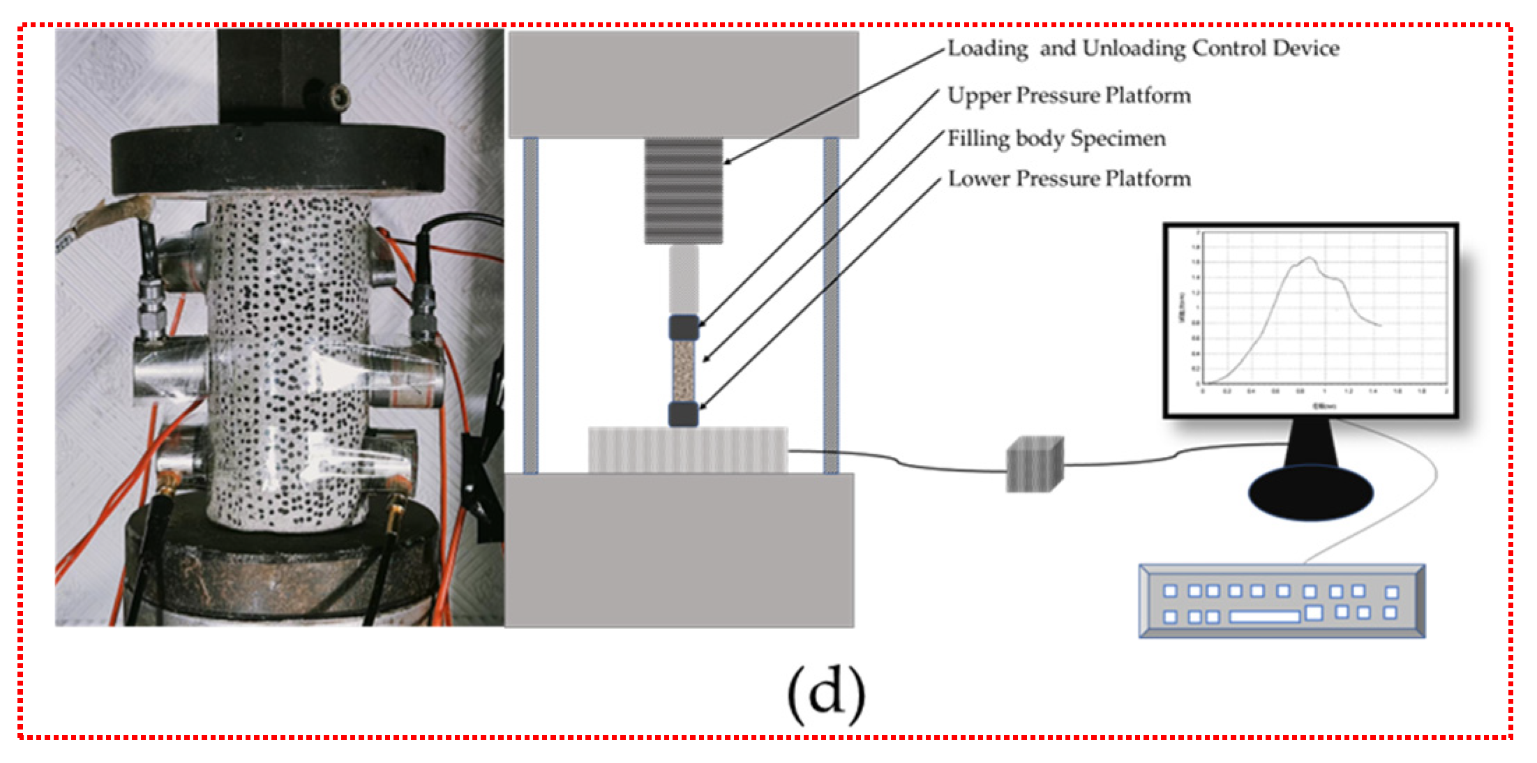
The loading equipment adopts a RMT-150C rock mechanics test system produced by Institute of Rock and Soil Mechanics, Chinese Academy of Sciences in Wuhan, China. The loading mode adopts displacement control. The loading rate is 0.002 mm/s. The AE acquisition system adopts a PCI-II AE win produced by PAC in the US. The sensor adopts UT-1000. The preamplifier gain is 40 dB; the sampling frequency is 1MSPS; and the threshold value is 40 dB. The infrasound sensor uses the MB3d microbarometer produced by Seismo Wave in Lannion, France, and the infrasound signal acquisition selects the digitally (MB3d) embedded low-consumption high-performance 24-bit ADC. The sensor can be set in the pressure output mode or pressure derivative output mode. The test materials and equipment are shown in Figure 1.

3. Results and Discussion

3.1. Backfill Mechanics Characteristics

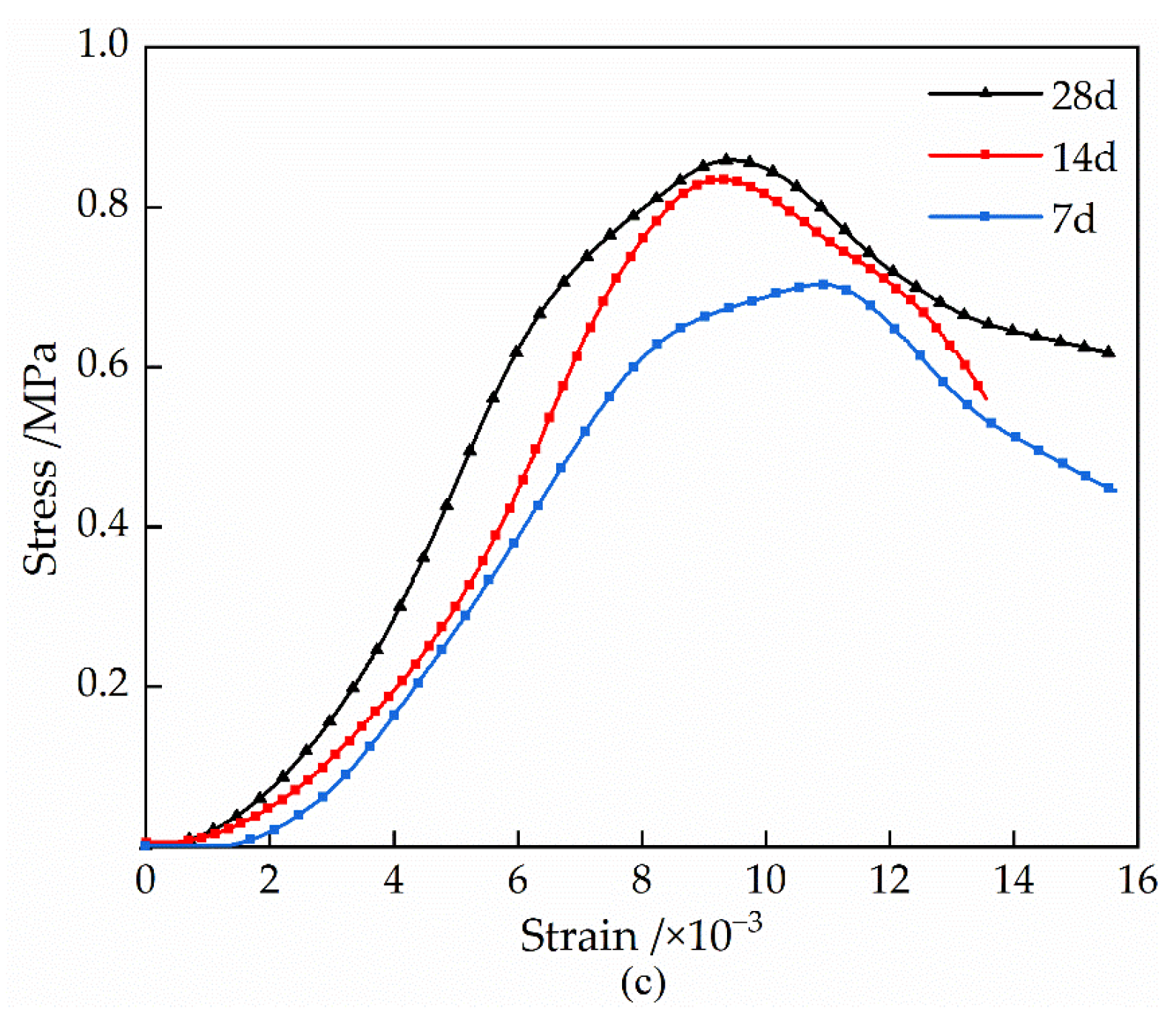
Uniaxial compression tests were carried out on three different cement–sand ratio backfill specimens with curing ages of 7 d, 14 d, and 28 d, and the stress–strain curves of the cemented backfill with unclassified tailings under uniaxial compression were obtained as shown in Figure 2. It can be seen from Figure 2 that the stress–strain curves of the cemented backfill with unclassified tailings at different curing ages have certain differences. That is, with the increase of the curing age, the slope of the straight section of the stress–strain curve of the backfill body increases, and the peak load increases. The strength and elastic modulus of the backfill body are significantly enhanced. At this time, the curing age is positively correlated with the peak stress and elastic modulus. With the extension of the curing age from 7 days to 28 days, the average compressive strength of backfill specimens with cement–sand ratios of 1:4, 1:6, and 1:8 increased from 0.95 MPa to 1.83 Mpa (an increase of 92.6%), 0.64 Mpa to 1.05 Mpa (an increase of 64.1%), and 0.40 Mpa to 0.70 Mpa (an increase of 75.0%), respectively. The average elastic modulus increased from 178.63 MPa to 259.32 Mpa (an increase of 45.2%), 117.62 MPa to 146.62 Mpa (an increase of 24.7%), and 75.32 MPa to 107.79 Mpa (an increase of 43.1%), respectively. The reason for the change is that with the gradual growth of the curing age, the amount of C-S-H gel generated by the cement hydration reaction gradually increases. The compactness of the internal structure of the backfill gradually increases, and the cohesion between the particles gradually increases, which hinders the initiation and expansion of the crack of the specimen. It inhibits the diffusion of energy inside the specimen, so that the energy storage limit of the cemented backfill gradually increases [33].

3.2. Acoustic Signal Ringing Count Characteristics

As a non-destructive monitoring method, acoustic emissions and infrasound can reflect the evolution characteristics of internal cracks in materials such as rocks and backfill in real time and can provide crucial discriminant information for the monitoring of instability and the failure of materials, such as rocks and backfill [17,18,19].
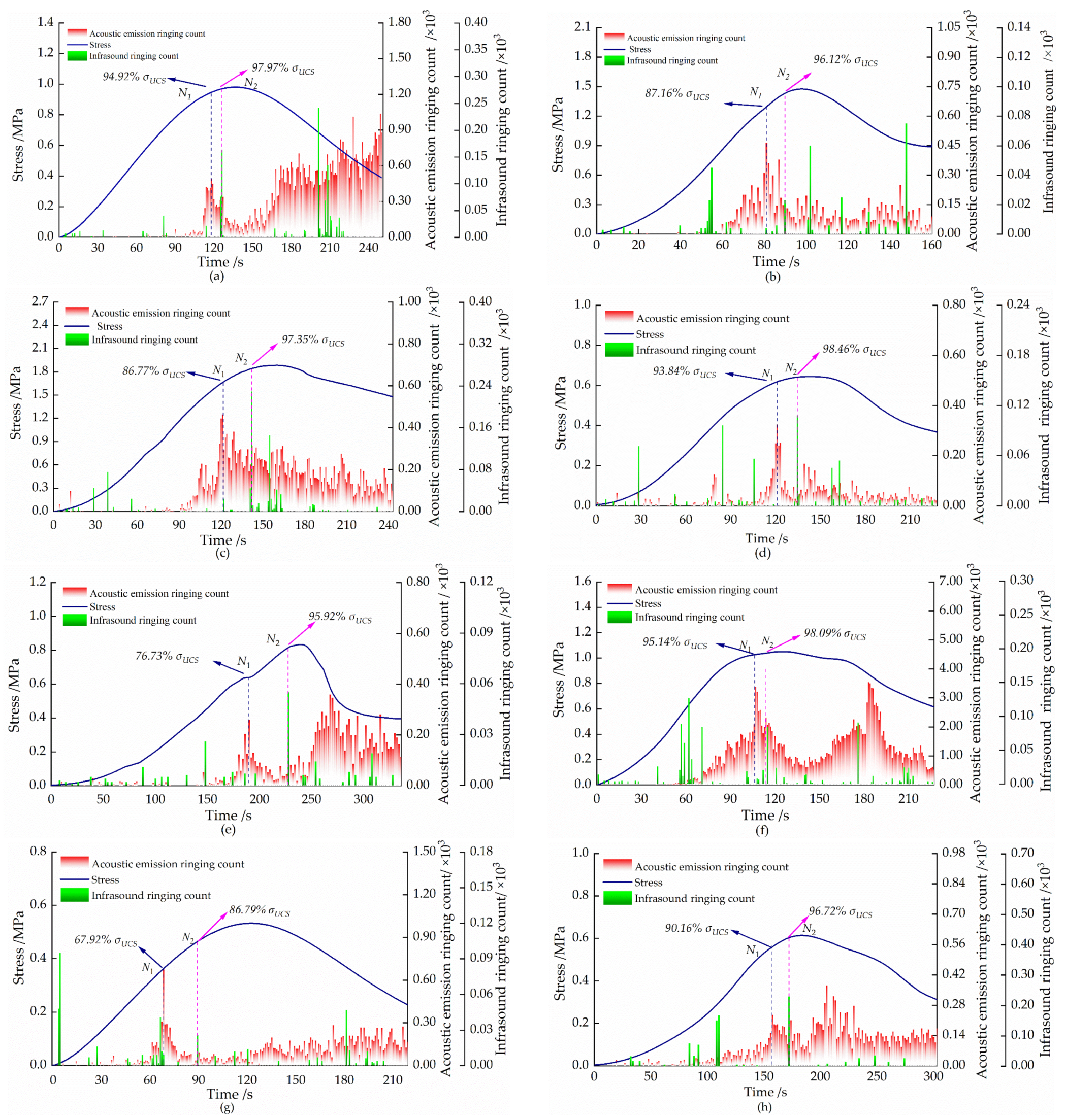
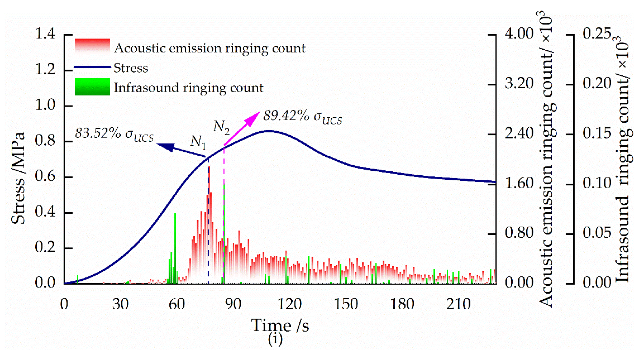
Figure 3 shows the curves of the acoustic emission and infrasound ringing count over time in the failure process of backfill specimens with different cement–sand ratios at different curing ages. From the diagram, it can be seen that the change rule of the acoustic emission ringing count is similar as a whole, showing a trend of “stabilizing–rising– falling–rising”. According to the change rule of the acoustic emission ringing count, the failure process is divided into four stages. The first stage is in the early stages of loading. The internal cracks of the backfill were compacted, and the acoustic emission signal was less. There was almost no obvious change in the ringing count. However, the friction between the particles in the backfill at this stage produced more infrasound signals; the infrasound ringing count was more active, and there was a “peak” phenomenon. In the second stage, the cracks in the backfill began to initiate and stably expand; the acoustic emission signals were generated, and the numbers began to increase; the ringing count showed an upward trend. At this stage, high-frequency signals were generated due to the initiation of crack propagation, and infrasound signals were less. In the third stage, the proportion of large cracks began to increase, and the acoustic emission ringing count began to drop sharply (N1 point in the picture; σ U C S represents the peak stress). When this dropped to the lowest point, the specimen was unstable and destroyed. At this stage, there was a “peak” (N2 point in the figure; σ U C S represents the peak stress). In the fourth stage, due to the large number of micro-cracks in the backfill, a macroscopic fracture zone was formed. The friction between the fracture zone produced a large number of acoustic emission and infrasound signals. The acoustic emission ringing count began to rise, and the infrasound ringing count began to fluctuate greatly.
In practical engineering, when using acoustic emissions or infrasound to monitor the stability of backfill, due to the complexity of the failure process of backfill, it is very difficult to predict its instability according to the decrease degree of the acoustic emission ringing count or the “peak” of the infrasound ringing count. However, it can be seen from Figure 3 that when the acoustic emission ringing count begins to decrease, the infrasound ringing count does not have multiple peaks before the rupture. Therefore, acoustic emissions combined with infrasound signals can be used to warn of the instability and failure of backfill. That is, after the ringing count of the acoustic emission begins to decrease (point N1 in the figure), the peak point of the infrasound ringing count (point N2 in the figure) appears for the first time as the early warning point of instability and the failure of backfill.

3.3. Acoustic Signal ib Value Characteristics

The variation of ib values can properly characterize the degree of the crack extension within materials. Studies show that increasing ib values indicate that the internal micro-rupture of the material is mainly small-scale damage [34,35,36]. Decreasing ib values indicate that the internal micro-rupture of the material is mainly large-scale damage. The stabilization of ib values indicates that the internal large rupture of the material has been completed and no further large damage will occur. The calculation formula of an ib value is as follows:
i b = log 10 N ( W 1 ) log 10 N ( W 2 ) ( a 1 + a 2 ) σ
where μ is average amplitude; σ is standard variance of amplitude; a 1 and a 2 are empirical parameters; N ( W 1 ) is the cumulative number of acoustic emission impacts with an amplitude greater than μ a 2 σ ; N ( W 2 ) is the cumulative number of acoustic emission impacts with an amplitude greater than μ + a 2 σ .
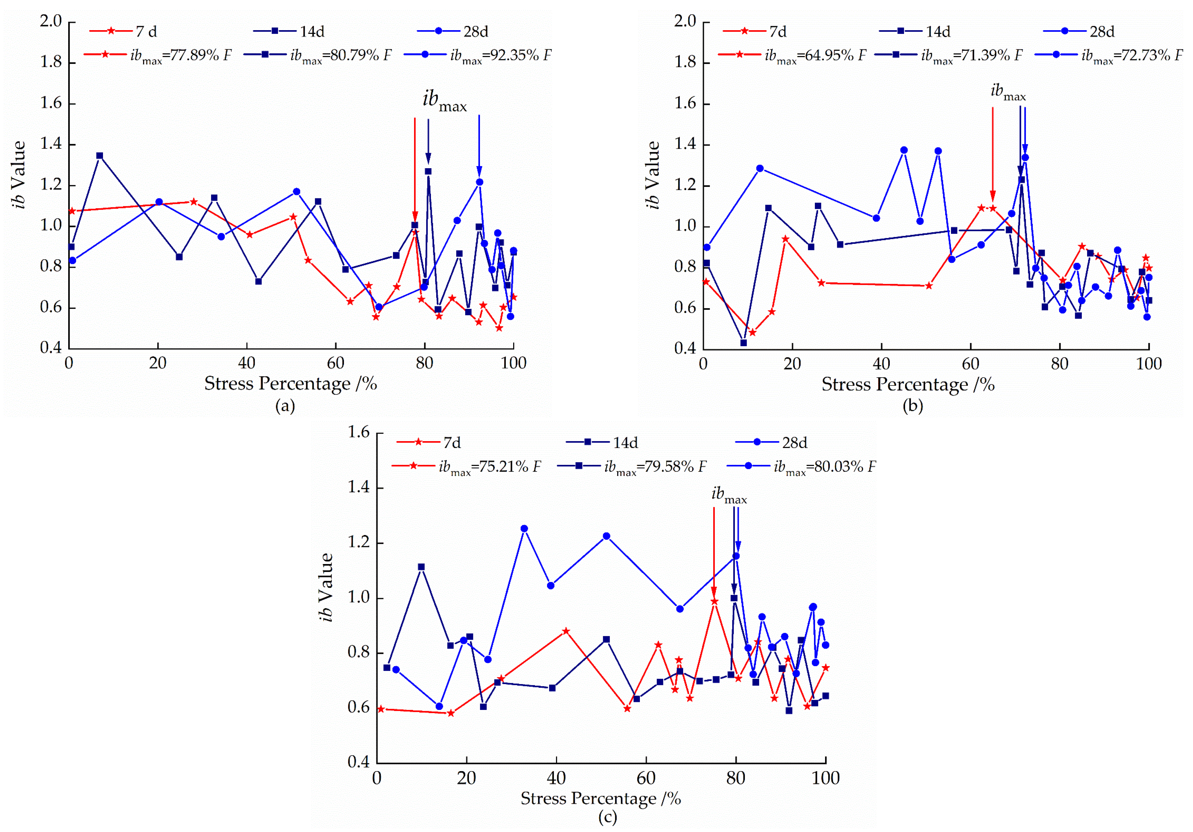
Through an analysis of the acoustic emission ib value during the damage of the backfill, its damage process acoustic emission ib value shows a certain regularity. As can be seen from Figure 4, at the early stage of loading (before a stress percentage of 30%), there are few acoustic emission events, at which time the ib value is small and fluctuates widely. As the load continues to increase until the peak stress, the overall ib value has no obvious change pattern. When the backfill is close to damage (the maximum value at this stage after the stress percentage of 60% is shown in the figure as ibmax), the ib value begins to decline in a jumping manner, and this phenomenon can provide a certain basis for predicting damage of the backfill.
From the perspective of the curing age, with an increase of the curing age, the average value of ib of the same cement–sand ratio backfill shows an increasing trend. That is, with an increase of the curing age, the micro-fracture form of the same cement–sand ratio backfill gradually changes from a large-scale fracture to a small-scale fracture. When the cement–sand ratio is 1:4, peak loads corresponding to the curing ages of 7 d, 14 d, and 28 d are 77.89%, 80.79%, and 92.35%, respectively. When the cement–sand ratio is 1:6, peak loads corresponding to the curing ages of 7 d, 14 d, and 28 d are 64.95%, 71.39%, and 72.73%, respectively. When the cement–sand ratio is 1:8, peak loads corresponding to the curing ages of 7 d, 14 d, and 28 d are 75.21%, 79.58%, and 80.03%, respectively. It is not difficult to see that the stress percentage corresponding to ibmax increases with the increase of the curing age. The reason for this is that with the increase of the curing age, the hydration reaction inside the backfill is more sufficient, and the generated cementing material further improves the compactness of the backfill, which makes the crack evolution more intense.
Due to the non-contact propagation of the acquisition method of infrasound signals, the noise will become an unavoidable factor affecting the signal analysis results during the processing of infrasound signals. In order to eliminate the environmental noise in the infrasound signal, the original digital signal is filtered. Various methods of signal filtering are commonly used, such as Fourier transform filtering, wavelet packet filtering, and wavelet threshold filtering [37]. In this paper, the wavelet threshold filtering method is used to filter the acquired original digital signal, and a wavelet decomposition and reconstruction of the original digital signal are performed. Figure 5 shows the ambient noise background signal. The analysis finds that the background signal amplitude is concentrated between −0.0025~0.0025 V, so the threshold value is taken as 0.0025 V.
The literature [16,17] suggests that anomalous infrasound mutations will occur before peak damage occurs in the material, so this test uses the analytical method of Equation (1) for the infrasound ib value.
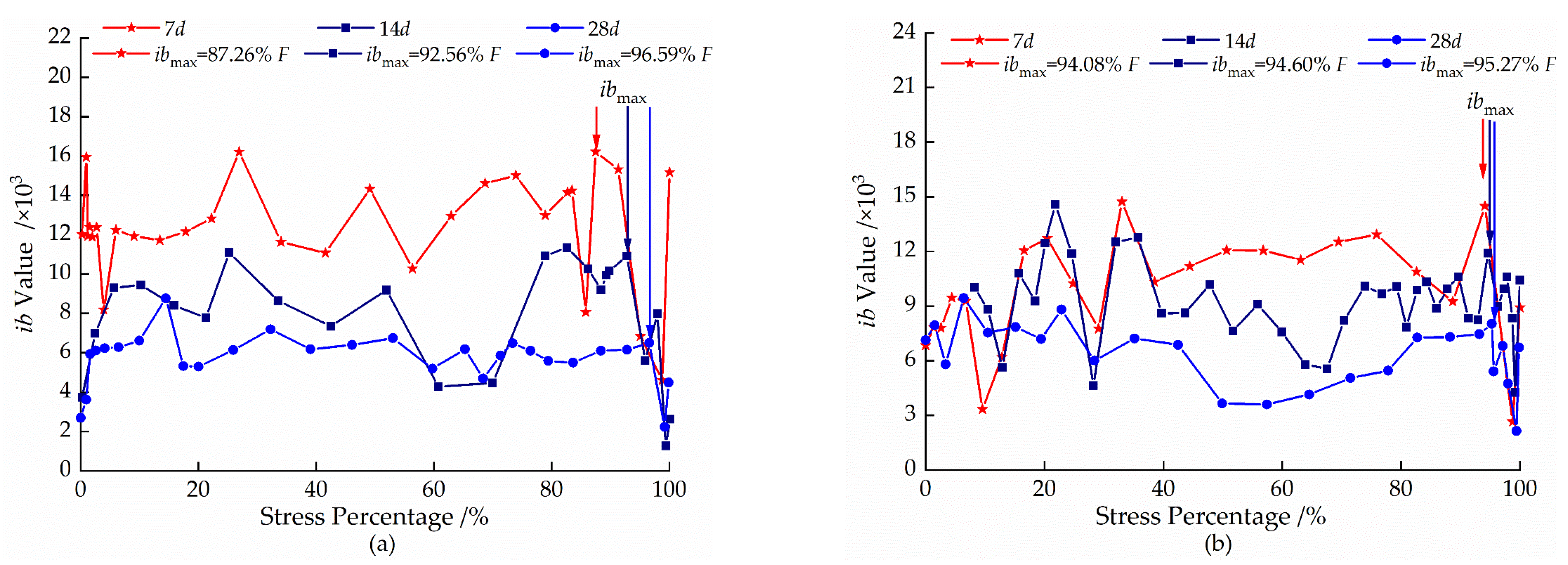
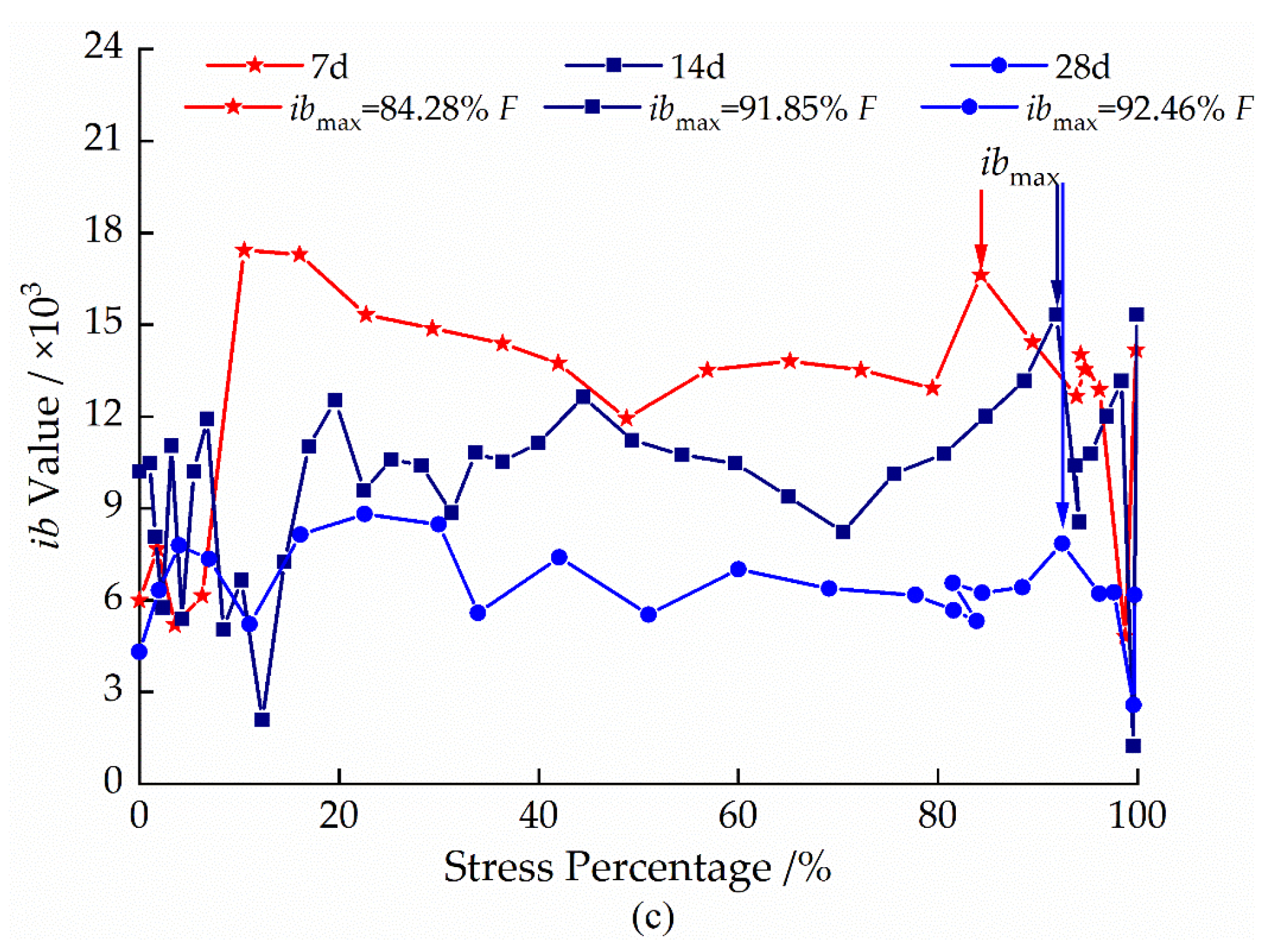
As can be seen from Figure 6, the infrasound ib value of the destruction process of the cemented backfill with unclassified tailings shows a certain pattern with the change of the stress percentage. With a stress percentage of 0~30% and the backfill in the pre-loading stage, due to friction and slip between the particles and a large number of low-energy friction-type infrasound signals the infrasound signal ib value fluctuates and gradually increases. With a stress percentage of 30~85% and the backfill in the middle of the loading stage, the backfill interior fractures gradually to the development of large-scale, internal fractures along the particle links which expand; the proportion of large-scale fractures begin to gradually increase, and the infrasound signal ib value fluctuations are relatively gentle and display a small decrease. The maximum value in this stage, after the stress percentage reaches 85% (ibmax), the filler internal microcracking achieves a quantitative to qualitative transformation. The formation of a macroscopic rupture zone occurs, and the infrasound signal ib value appears to fall. The percentage of stress corresponding to ibmax increases with the increase of the curing age of the backfill with the same cement–tailing ratio. The start of the decline in a jumping manner of the infrasonic signal ib value represents the formation of the macroscopic rupture zone of the backfill, and this feature can provide certain criteria for the destruction of the backfill.
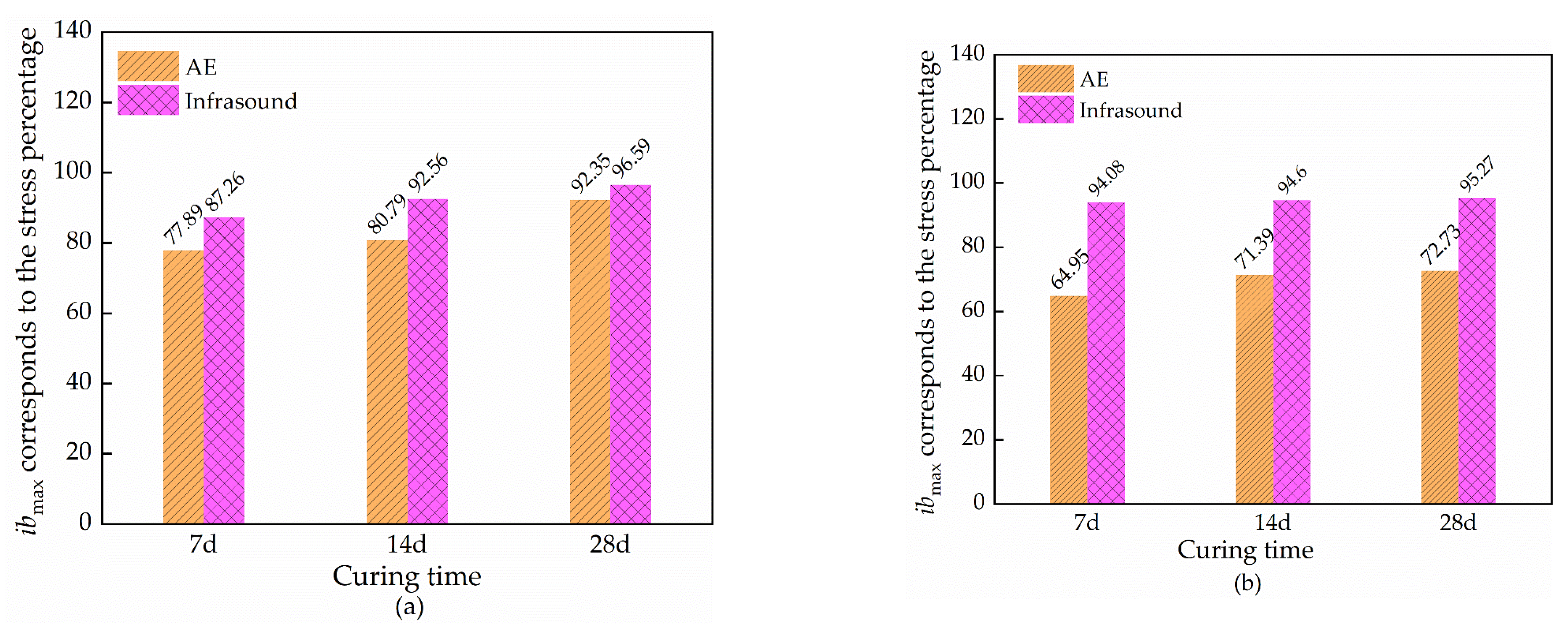
From Figure 7, it can be seen that the stress percentages corresponding to infrasound ibmax and acoustic emission ibmax during the damage of the backfill both increase with the age of maintenance. The percentage of stress corresponding to the infrasound ibmax in the failure process of the backfill is compared with the percentage of stress corresponding to the acoustic emission ibmax. It can be seen that the percentage of stress corresponding to the infrasound signal is always higher than that corresponding to the acoustic emission signal ibmax, because the acoustic emission signal decays more rapidly than the infrasound signal. In the pre-loading period (before a 60% stress percentage), the infrasound picks up more signals than the acoustic emission, and in the post-loading period (after a 60% stress percentage), the acoustic emission picks up more signals than the infrasound. Therefore, a combined analysis of acoustic emission ib values and infrasound ib values is used to better capture the crack-evolution information of the filling damage process.

3.4. Spectral Evolution Characteristics of Acoustic Signals

Waveform analysis can extract key information from the acoustic signal, and its extracted spectral features can reflect the acoustic signal characteristics more comprehensively. Due to the complexity and global nature of the spectral characteristics of the acoustic signal during the destruction of material, only the dominant frequency can represent only part of the characteristics of the acoustic signal, but not all of it. It has been demonstrated that the acoustic signal during the destruction of rock materials can appear as a secondary dominant frequency phenomenon [38,39,40,41]. Based on this, this experiment unifies the study of the acoustic signal dominant frequency and the secondary dominant frequency. The dominant frequency ratio F proposed in the literature [41] is a parameter that can characterize the spectral features of the acoustic signal waveform. Due to the complexity of the damage process of backfill and its internal crack evolution, the concept of the dominant frequency ratio FS of the infrasonic signal is proposed in this study based on the parameter FAE of the dominant frequency ratio of the acoustic emission signal.
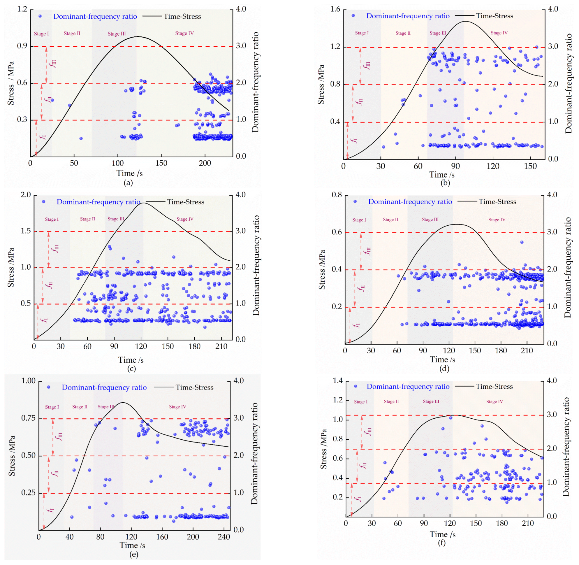
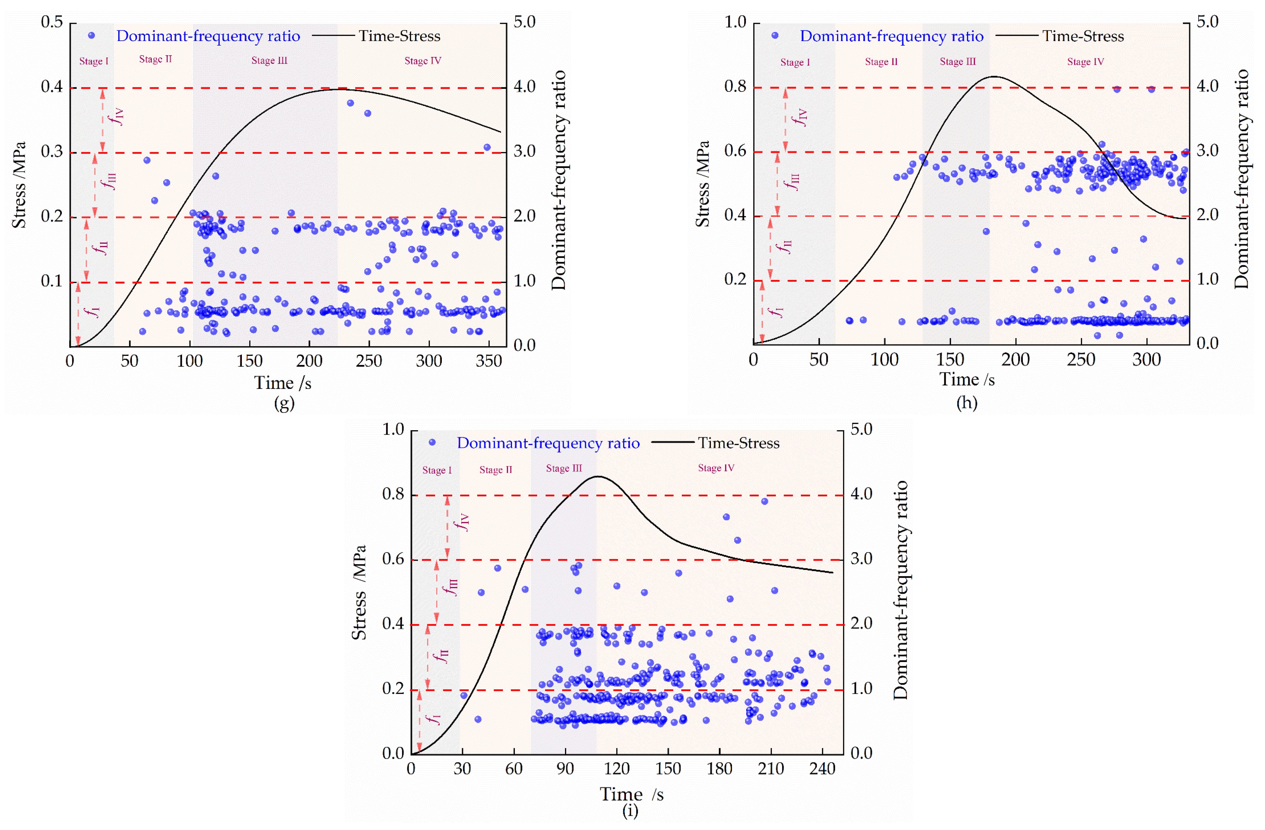
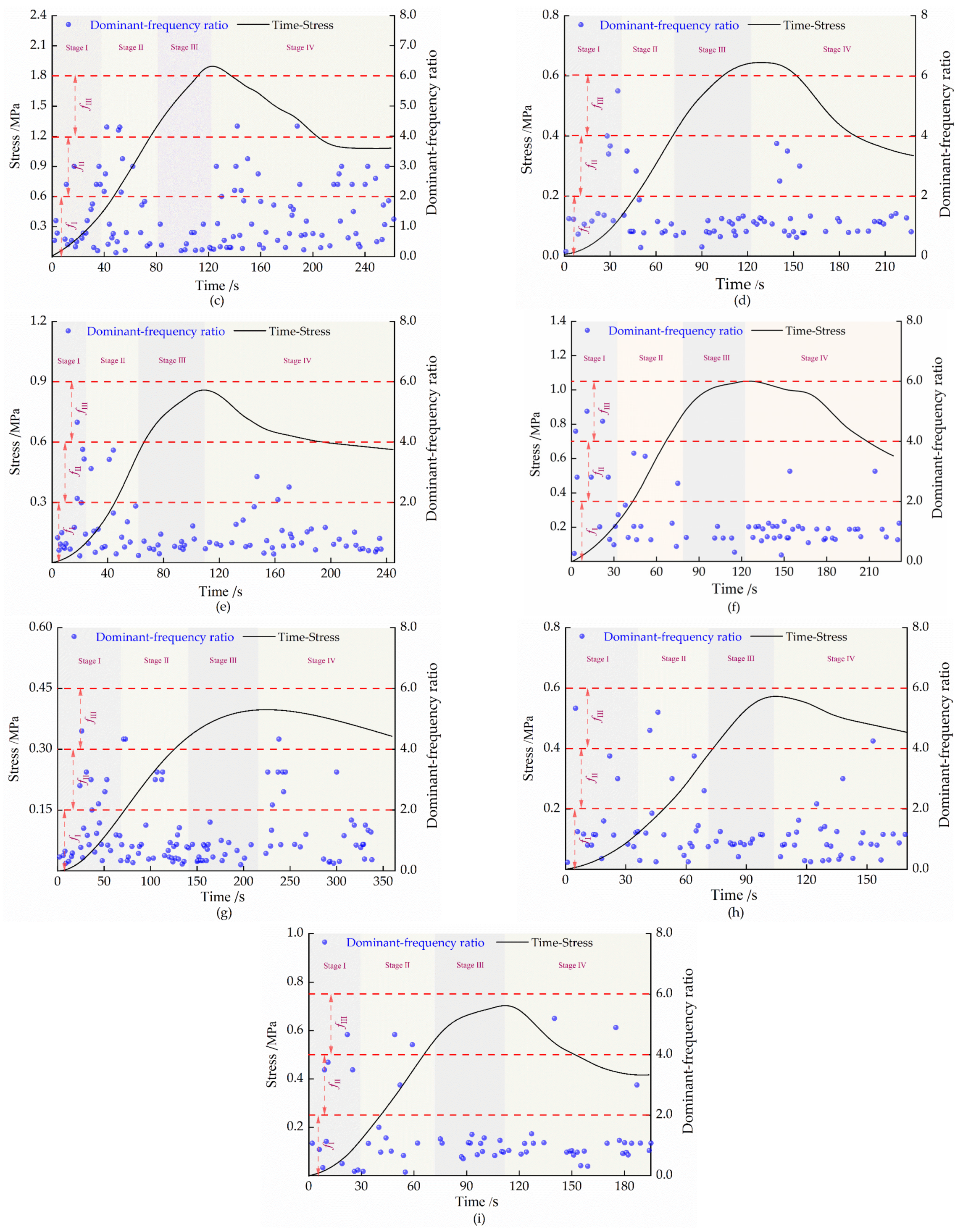
Figure 8 and Figure 9 show the evolution characteristics of the acoustic emission signal’s dominant frequency ratio FAE and the infrasound signal’s dominant frequency ratio FS during the damage process of backfill at different curing ages. As can be seen from the figures, the stress–time curve can be divided into four stages, and the corresponding emission signal’s dominant frequency ratio FAE and infrasound signal’s dominant frequency ratio FS of each stage also have different characteristics.
The dominant frequency ratio FAE of the acoustic emission signal during damage of the backfill is mainly gathered in three frequency bands in the form of strips (the backfill with a cement–sand ratio of 1:8 has four frequency bands).
(a)
Compaction stage (stage I): The original micro-fractures inside the backfill start to be compressed at this stage, and the acoustic emission signal is not generated. The backfill with a cement–sand ratio of 1:4 has a better structural denseness due to the increase of the cementitious agent content, so the FAE does not exist in the compacting stage.
(b)
Crack stable growth (stage II): In this stage, the original micro-cracks inside the backfill are basically closed, and new cracks begin to sprout and develop. The total strain energy absorbed by the filler is mainly stored in the form of elastic energy inside the backfill; the acoustic emission signal begins to increase, and FAE begins to appear in the fI, fII or fI, fIII frequency band. In addition, with the prolongation of the curing age and the amount of C-S-H gel, the internal hydration reaction product of the backfill increases, and the internal structure becomes denser. The bonding force between the particles increases, and the crack expansion pattern becomes complex. the number of FAE starts to increase. The backfill with a cement–tailing ratio of 1:8, due to the increase of the tail–sand content, does not have a sufficient hydration reaction in the early curing stage, which makes the acoustic emission signal more complex at this stage, and increases the FAE in the fI band.
(c)
Crack unsteady growth (stage III): An accelerated development of the internal cracks in backfill forms at this stage, and the FAE starts to surge. The FAE appears in the three frequency bands of fI, fII, and fIII, and the three frequency bands are connected to each other to form a wider band in some time periods, indicating that the acoustic emission signal mode becomes more complex, and the crack evolution inside the backfill is more intense.
(d)
Post-peaking phase (stage IV): At this stage, the internal crack of the backfill expands and penetrates rapidly, which eventually leads to the complete destruction of the backfill, and the FAE appears intensively in all three bands. The backfill with a cement–tailing ratio of 1:8, due to an increase of the tail–sand ratio, displays friction between the particles after destruction is more intense, causing FAE to start to appear in the fIV band.
As can be seen from Figure 9, the infrasonic wave signal Fs changes periodically with the failure process of filling the body at different curing ages. In the compaction stage (stage I) and the stable crack propagation stage (stage II), Fs is sporadically distributed in the fII and fIII frequency bands and is clustered in the fI frequency band. This phenomenon is mainly caused by the friction of particles inside the backfill, and it does not change with the curing age. In the compaction stage (stage I) and the crack stable growth stage (stage II), the FS are distributed sporadically in the fII and fIII bands and are aggregated in the fI band, which is mainly due to the friction of particles inside the backfill at this stage; these distribution characteristics do not change with the curing age.
It can be seen from Figure 8 and Figure 9 that the dominant frequency ratio F exists in both the acoustic emission signal and the infrasound signal during the failure of the backfill. However, FS is distributed between 0 and 6 and is mainly concentrated between 0 and 2. Furthermore, there is only a small change in its distribution regularity with the change of the curing age. FAE is distributed between 0 and 3 and is mainly concentrated between 0 and 2. In addition, there is a large change in its distribution regularity with the change of the curing age.

3.5. Evolution Characteristics of Class A and B Signals in the Failure Process of Backfill

According to the relationship between the dominant frequency ratio and 1, the acoustic emission or infrasound signals can be classified into two classes: class A signals (0 < F < 1), whose dominant frequency is smaller than the secondary dominant frequency, and class B signals (1 < F), whose dominant frequency is larger than the secondary dominant frequency [41].
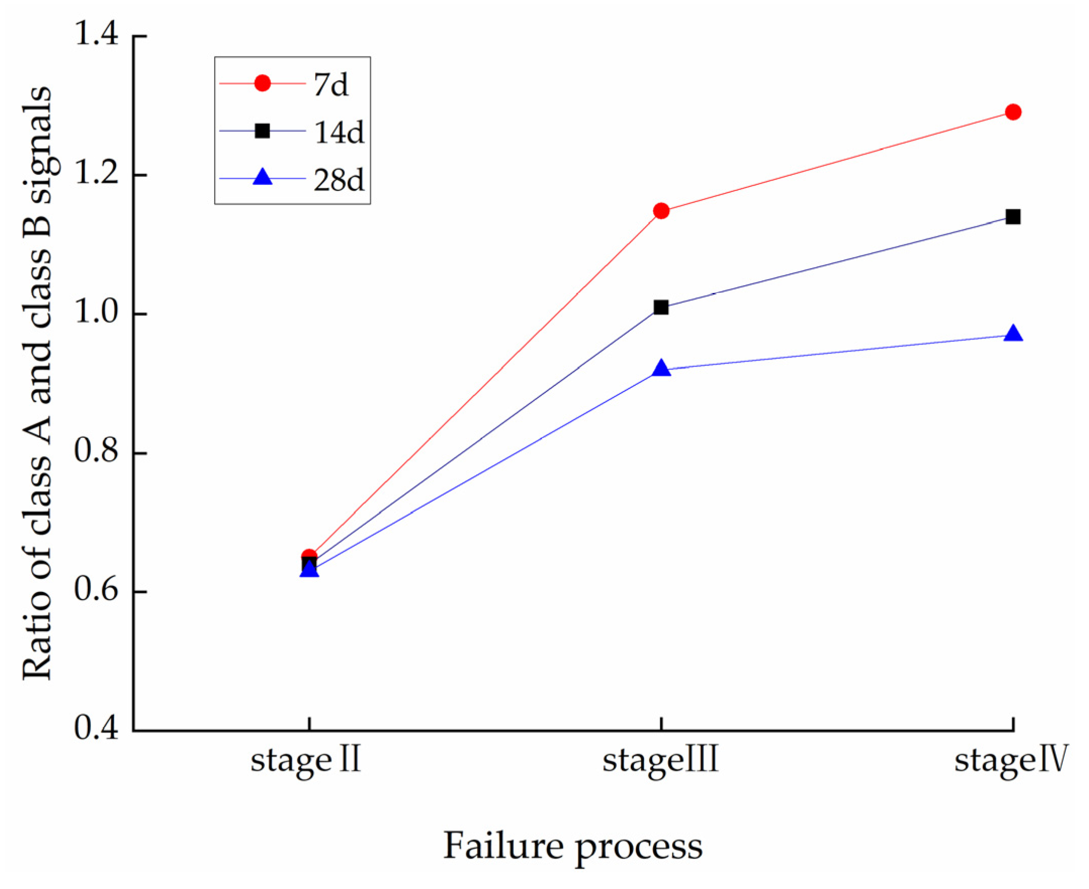
In order to limit the space, representative specimens were selected for analysis. Figure 10 and Figure 11 show the variation curves of the number ratio (A:B) of class A and B of the acoustic signals at each stage of the rupture process of the backfill, with a cement–tailing ratio of 1:6 at different curing ages.
From the analysis of Figure 10, it can be seen that the ratio of the number of class A and B of acoustic emission signals gradually increased during the rupture of the filling, and the average value increased from 0.65 to 1.03 from stage II to stage III. Furthermore, the ratio of the number of class A and B of the acoustic emission signals changed from the dominance of the number of class B of signals to the approximate equality of the number of class A and B of signals. The difference of the number of class A and B signals of acoustic emissions is small in stage III and stage IV. In stage II, the ratio of class A and B signals is smaller (less than 0.7). That is, the crack stable growth stage is dominated by class B of the acoustic emission signals, whose dominant frequency is larger than the secondary dominant frequency. From stage III to stage IV, the change of the ratio of the number of class A and B signals ranged from 0.92 to 1.29, i.e., the number of class A and B of the acoustic emission signals in stage III and stage IV are similar. On the other hand, from the perspective of the curing age, the difference between the number of class A and B signals decreases with the increase of the curing age from stage II to stage III, and the same pattern is observed from stage III to stage IV, but the decrease is smaller.
It can be seen from Figure 11 that the variation law of the number ratio of class A and B signals of the infrasound in the fracture process of filling the body is similar as a whole, showing a trend of “decrease–increase–decrease”. From stage I to stage II, the ratio of the number of class A and B signals is relatively small (less than 1.5) and decreases slowly. The number of class A and B of the infrasound signals is similar in stage I and stage II, and the relationship between the number of these two classes of signals does not change significantly. In stage III, the ratio of class A and B signals rises rapidly and reaches a maximum value in the range of 1.75 to 3.2.In other words, in stage III, class A of the infrasound signal with a dominant frequency less than the secondary dominant frequency is dominant. In stage IV, the ratio of class A and B of the infrasound signals decreases, and its value is similar to that of stage I and stage II.
Based on the above analysis, it can be seen that the ratio of the number of class A and B of the acoustic emission signals during the rupture of the backfill has a good correlation with the age of the filling. In other words, when the curing time of the filler increases, the change in the number of class A and B of the acoustic emission signals during the damage of the filler decreases. In addition, the ratio of class A and B of the acoustic signals will increase significantly in stage III, which can be used as a criterion for the backfill to enter the crack’s unsteady growth.

4. Conclusions

In this paper, backfill samples with different cement–sand ratios and curing ages were designed and obtained, and then, the mechanical and acoustic characteristics of the cemented backfill with unclassified tailings were studied by a uniaxial compression acoustic emission test. Finally, a failure prediction of the backfill was made.
(1)
Under the condition of uniaxial compression, with an increase of the curing age, the slope of the straight section of the stress–strain curve of the backfill increases, and the peak load increases. The peak strength and elastic modulus of the backfill are positively correlated with the curing age.
(2)
During the failure process of backfill, the acoustic emission ringing count shows a trend of “stabilizing–rising–falling–rising”, and the infrasound ringing count will show a “multi-peak” phenomenon. The acoustic ib value shows a certain regularity in the process of backfill failure, and the ib value begins to decline in a jumping manner when it is close to failure. With the increase of the curing age, the stress percentage corresponding to ibmax increases.
(3)
The dominant frequency ratio of the acoustic emission signal (FAE) during the damage of backfill is mainly distributed between 0~3. The dominant frequency ratio of the infrasound signal (FS) is mainly distributed between 0~6.
(4)
The ratio of the number of class A and B signals of the acoustic emission in the damage process of backfill is increases. The class A and B signals of the infrasound show a phenomenon of “decrease–increase–decrease”. The ratio of the number of class A and B of the acoustic emission signal and the infrasound signal in the crack’s unsteady growth will show a surge phenomenon.

Author Contributions

Conceptualization, K.Z. and W.L.; methodology, W.L.; software, W.L.; validation, W.L., P.Z. and H.D.; formal analysis, W.L., H.D., Y.L. and Z.L.; investigation, W.L.; resources, M.Z.; data curation, W.L. and W.X.; writing—original draft preparation, W.L.; writing—review and editing, W.L.; visualization, P.Z.; supervision, K.Z.; project administration, K.Z.; funding acquisition, K.Z. All authors have read and agreed to the published version of the manuscript.

Funding

This research was funded by the National Natural Science Foundation of China (52164004, 52104086), the Key research and development program of Jiangxi Province, China (20212BBG71009), the post-doctoral research program of Jiangxi Province, China (2020KY39), and the Technology Research Project of Jiangxi Provincial Department of Education (GJJ209413).

Institutional Review Board Statement

Not applicable.

Informed Consent Statement

Not applicable.

Data Availability Statement

Not applicable.

Acknowledgments

The authors would like to acknowledge the Jiangxi University of Science and Technology.

Conflicts of Interest

The authors declare no conflict of interest.

References

  1. Jafari, M.; Shahsavari, M.; Grabinsky, M. Drained triaxial compressive shear response of cemented paste backfill (CPB). Rock Mech. Rock Eng. 2021, 54, 3309–3325. [Google Scholar] [CrossRef]
  2. Tang, Y.; Zheng, J.; Guo, L.; Zhao, Y. Effect of gypsum addition on the mechanical and microstructural performance of sulphide-rich cemented paste backfill. Minerals 2021, 11, 283. [Google Scholar] [CrossRef]
  3. Zhang, Y.; Feng, X.T.; Yang, C.; Zhang, X.; Sharifzadeh, M.; Wang, Z. Fracturing evolution analysis of Beishan granite under true triaxial compression based on acoustic emission and strain energy. Int. J. Rock Mech. Min. Sci. 2019, 117, 150–161. [Google Scholar] [CrossRef]
  4. Zhang, Y.; Zhao, G.F.; Li, Q. Acoustic emission uncovers thermal damage evolution of rock. Int. J. Rock Mech. Min. Sci. 2020, 132, 104388. [Google Scholar] [CrossRef]
  5. Cheng, A.; Zhang, Y.; Dai, S.; Dong, F.; Zeng, W.; Li, D. Space-time evolution of acoustic emission parameters of cemented backfill and its fracture prediction under uniaxial compression. Rock Soil Mech. 2019, 40, 2965. [Google Scholar]
  6. Xu, W.; Cao, Y.; Liu, B. Strength efficiency evaluation of cemented tailings backfill with different stratified structures. Eng. Struct. 2019, 180, 18–28. [Google Scholar] [CrossRef]
  7. Marsden, O.; Bogey, C.; Bailly, C. A study of infrasound propagation based on high-order finite difference solutions of the Navier-Stokes equations. J. Acoust. Soc. Am. 2014, 135, 1083–1095. [Google Scholar] [CrossRef]
  8. Zhou, Q.; Liu, J.; Wu, A.; Wang, H.J. Early-age strength property improvement and stability analysis of unclassified tailing paste backfill materials. Int. J. Miner. Metall. Mater. 2020, 27, 1191–1202. [Google Scholar] [CrossRef]
  9. Chen, X.; Shi, X.; Zhou, J.; Li, E.; Qiu, P.; Gou, Y. High strain rate compressive strength behavior of cemented paste backfill using split Hopkinson pressure bar. Int. J. Min. Sci. Technol. 2021, 31, 387–399. [Google Scholar] [CrossRef]
  10. Liu, L.; Fang, Z.; Qi, C.; Zhang, B.; Guo, L.; Song, K.I. Experimental investigation on the relationship between pore characteristics and unconfined compressive strength of cemented paste backfill. Constr. Build. Mater. 2018, 179, 254–264. [Google Scholar] [CrossRef]
  11. Xue, G.; Yilmaz, E.; Song, W.; Yilmaz, E. Influence of fiber reinforcement on mechanical behavior and microstructural properties of cemented tailings backfill. Constr. Build. Mater. 2019, 213, 275–285. [Google Scholar] [CrossRef]
  12. Lu, H.; Liang, P. Mechanical behaviour and failure characteristics of cemented paste backfill under lateral unloading condition. Int. J. Min. Miner. Eng. 2020, 11, 66–83. [Google Scholar] [CrossRef]
  13. Li, M.; Liu, X.; Liu, X. Infrasound signal classification based on spectral entropy and support vector machine. Appl. Acoust. 2016, 113, 116–120. [Google Scholar] [CrossRef]
  14. Kui, Z.; Zeyuan, Y.; Peng, Z. Infrasound characteristics of cemented tailing filling material under uniaxial compression. J. China Coal Soc. 2019, 44, 92–100. [Google Scholar]
  15. Qiao, C.; Xu, F.; Su, P.; Liu, Y.; Zhang, Y.; Zhu, H.; Huang, H.; Huang, M.; Chen, J.; Liu, D. Experimental Study on the Features of Infrasonic Waves of Sandstone under Shear Load. Appl. Sci. 2021, 11, 11552. [Google Scholar] [CrossRef]
  16. Chai, S.; Li, L.J.; Ju, Z.Q.; Zou, Y.; Zhang, Y.Z. Test research on infrasound wave of granite damage course under dynamic uniaxial compression. In Key Engineering Materials; Trans Tech Publications Ltd.: Wollerau, Switzerland, 2011; Volume 460, pp. 692–697. [Google Scholar]
  17. Zhu, X.; Xu, Q.; Zhou, J.; Tang, M. Experimental study of infrasonic signal generation during rock fracture under uniaxial compression. Int. J. Rock Mech. Min. Sci. 2013, 60, 37–46. [Google Scholar] [CrossRef]
  18. Jia, B.; Wei, J.; Wen, Z.; Wang, Y.G.; Jia, L.X. The analysis of energy characteristics of infrasonic signal in coal sample with different strength under loading process. Acta Acust. United Acust. 2017, 103, 795–802. [Google Scholar] [CrossRef]
  19. Liu, X.; Liu, Z.; Li, X.; Gong, F.; Du, K. Experimental study on the effect of strain rate on rock acoustic emission characteristics. Int. J. Rock Mech. Min. Sci. 2020, 133, 104420. [Google Scholar] [CrossRef]
  20. Du, K.; Li, X.; Tao, M.; Wang, S. Experimental study on acoustic emission (AE) characteristics and crack classification during rock fracture in several basic lab tests. Int. J. Rock Mech. Min. Sci. 2020, 133, 104411. [Google Scholar] [CrossRef]
  21. Yang, J.; Mu, Z.L.; Yang, S.Q. Experimental study of acoustic emission multi-parameter information characterizing rock crack development. Eng. Fract. Mech. 2020, 232, 107045. [Google Scholar] [CrossRef]
  22. Huang, Y.; Yang, W.; Zhao, A.; Guo, W. Shear Strength and Re-Failure Characteristics of Intact Red Sandstone and Grouting-Reinforced Body of Fractured Red Sandstone under Different Shear Angles. Minerals 2022, 12, 1580. [Google Scholar] [CrossRef]
  23. Zhao, K.; Yu, X.; Zhu, S.; Yan, Y.; Zhou, Y.; He, Z.; Song, Y.; Huang, M. Acoustic emission fractal characteristics and mechanical damage mechanism of cemented paste backfill prepared with tantalum niobium mine tailings. Constr. Build. Mater. 2020, 258, 119720. [Google Scholar] [CrossRef]
  24. Lv, H.; Peng, K.; Shang, X.Y.; Wang, Y.Q.; Liu, Z.P. Experimental research on the mechanical and acoustic emission properties of layered sandstone during tensile failure. Theor. Appl. Fract. Mech. 2022, 118, 103225. [Google Scholar] [CrossRef]
  25. Sun, L.; Long, Y.; Li, X.; Jiang, Z.; Fan, Y.; Wang, Z.; Han, X. Effect of Loading Rate on the Mechanical Properties of Weakly Cemented Sandstone. Sustainability 2023, 15, 2750. [Google Scholar] [CrossRef]
  26. Xu, X.; Zhou, Y.; Chen, W.; Gao, Y.; Fu, Q.; Liu, X.; Feng, C. Macro-Microscopic Deterioration Behavior of Gypsum Rock after Wetting and Its Constitutive Model Based on Acoustic Emission. Minerals 2022, 12, 1168. [Google Scholar] [CrossRef]
  27. Zhao, K.; Yu, X.; Zhu, S.; Zhou, Y.; Wang, Q.; Wang, J. Acoustic emission investigation of cemented paste backfill prepared with tantalum–niobium tailings. Constr. Build. Mater. 2020, 237, 117523. [Google Scholar] [CrossRef]
  28. Huang, C.; He, W.; Lu, B.; Wang, M.; Li, S.; Xiao, C. Study on Acoustic Emission and Coda Wave Characteristics of Layered Cemented Tailings Backfill under Uniaxial Compression. Minerals 2022, 12, 896. [Google Scholar] [CrossRef]
  29. Qiu, H.; Zhang, F.; Liu, L.; Huan, C.; Hou, D.; Kang, W. Experimental study on acoustic emission characteristics of cemented rock-tailings backfill. Constr. Build. Mater. 2022, 315, 125278. [Google Scholar] [CrossRef]
  30. Wang, J.; Fu, J.; Song, W.; Zhang, Y.; Wang, Y. Mechanical behavior, acoustic emission properties and damage evolution of cemented paste backfill considering structural feature. Constr. Build. Mater. 2020, 261, 119958. [Google Scholar] [CrossRef]
  31. Zhang, H.; Guo, W. Acoustic Emission Waveform Characteristics of Red Sandstone Failure under Uniaxial Compression after Thermal Damage. Sustainability 2022, 14, 13285. [Google Scholar] [CrossRef]
  32. Li, J.; Huang, Y.; Qi, W.; Kong, G.; Song, T. Loose gangues backfill body’s acoustic emissions rules during compaction test: Based on solid backfill mining. Comput. Model. Eng. Sci. 2018, 115, 85–103. [Google Scholar]
  33. Hou, Y.Q.; Yin, S.H.; Cao, Y.; Dai, C.Q. Analysis of damage characteristics and energy dissipation of cemented tailings backfill with different curing ages under uniaxial compression. J. Cent. South Univ. Sci. Technol. 2020, 7, 1955–1965. [Google Scholar]
  34. Zhao, K.; Wang, X.; Wang, L.; Zeng, P.; Yang, D.; Jin, J. Investigation of the crack and acoustic emission behavior evolution of red sandstone subjected to water. Theor. Appl. Fract. Mech. 2022, 120, 103419. [Google Scholar] [CrossRef]
  35. Colombo, I.S.; Main, I.G.; Forde, M.C. Assessing damage of reinforced concrete beam using “b-value” analysis of acoustic emission signals. J. Mater. Civ. Eng. 2003, 15, 280–286. [Google Scholar] [CrossRef]
  36. Tayfur, S.; Alver, N.; Saatci, S. Evaluation of acoustic emission activities in a steel fiber reinforced concrete beam by Ib value analysis. J. Fac. Eng. Archit. Gazi Univ. 2019, 2019, 309–318. [Google Scholar]
  37. Hong, F. Non-Stationary Signal Feature Extraction Method and Its Application; Science Publishing Company: Beijing, China, 2013; pp. 125–134. [Google Scholar]
  38. Jia, X.N. Experimental Study on Acoustic Emission Eigen-Frequency Spectrum Features of Strain Bursts. Ph.D. Thesis, University of Mining and Technology, Beijing, China, 2013. [Google Scholar]
  39. Mei, F.; Hu, C.; Li, P.; Zhang, J. Study on main Frequency precursor characteristics of Acoustic Emission from Deep buried Dali Rock explosion. Arab. J. Geosci. 2019, 12, 1–11. [Google Scholar] [CrossRef]
  40. Nan, L.; Enyuan, W.; Enlai, Z.; Yankun, M.; Fule, X.; Weihua, Q. Experiment on acoustic emission of rock damage and fracture under cyclic loading and multi-stage loading. J. China Coal Soc. 2010, 35, 1099–1103. [Google Scholar]
  41. Zhang, Y.B.; Liang, P.; Sun, L.; Tian, B.Z.; Yao, X.L.; Liu, X.X. Spectral characteristics of AE in the process of saturated granite fracture under uniaxial compression. Rock Soil Mech. 2019, 40, 2497–2506. [Google Scholar]
Figure 1. Test materials and equipment. (a) Backfill specimen; (b) acoustic emission system; (c) infrasonic wave acquisition system; (d) test loading system.
Sustainability 15 07177 g001aSustainability 15 07177 g001b
Figure 2. Stress–strain curve of the cemented backfill. (a) Test specimen with a 1:4 cement–sand ratio; (b) test specimen with a 1:6 cement–sand ratio; (c) test specimen with a 1:8 cement–sand ratio.
Sustainability 15 07177 g002aSustainability 15 07177 g002b
Figure 3. Acoustic emission and infrasonic ringing count—stress versus time. (ac) Test specimen with a 1:4 cement–sand ratio and a 7~28-day curing age; (df) test specimen with a 1:6 cement–sand ratio and a 7~28-day curing age; (gi) test specimen with a 1:8 cement–sand ratio and a 7~28-day curing age.
Sustainability 15 07177 g003aSustainability 15 07177 g003b
Figure 4. Relationship between ib values and the stress percentage of acoustic emission signals. (a) Test specimen with a 1:4 cement–sand ratio; (b) test specimen with a 1:6 cement–sand ratio; (c) test specimen with a 1:8 cement–sand ratio.
Sustainability 15 07177 g004
Figure 5. Background signal of environmental noise.
Sustainability 15 07177 g005
Figure 6. Infrasound signal ib value–stress percentage relationship. (a) Test specimen with a 1:4 cement–sand ratio; (b) test specimen with a 1:6 cement–sand ratio; (c) test specimen with a 1:8 cement–sand ratio.
Sustainability 15 07177 g006aSustainability 15 07177 g006b
Figure 7. Stress percentage relationship of acoustic signal ibmax. (a) Test specimen with a 1:4 cement–sand ratio; (b) test specimen with a 1:6 cement–sand ratio; (c) test specimen with a 1:8 cement–sand ratio.
Sustainability 15 07177 g007aSustainability 15 07177 g007b
Figure 8. Change of dominant frequency ratio of the acoustic emission in the failure process of backfill. (ac) Test specimen with a 1:4 cement–sand ratio and a 7~28-day curing age; (df) test specimen with a 1:6 cement–sand ratio and a 7~28-day curing age; (gi) test specimen with a 1:8 cement–sand ratio and a 7~28-day curing age.
Sustainability 15 07177 g008aSustainability 15 07177 g008b
Figure 9. Change of dominant frequency ratio of infrasonic waves in the failure process of backfill. (ac) Test specimen with a 1:4 cement–sand ratio and a 7~28-day curing age; (df) test specimen with a 1:6 cement–sand ratio and a 7~28-day curing age; (gi) test specimen with a 1:8 cement–sand ratio and a 7~28-day curing age.
Sustainability 15 07177 g009aSustainability 15 07177 g009b
Figure 10. Change curves of the number ratio of class A and B of the acoustic emission signals in the failure process of backfill.
Sustainability 15 07177 g010
Figure 11. Change curves of the number ratio of class A and B in the infrasound signals in the failure process of backfill.
Sustainability 15 07177 g011
Disclaimer/Publisher’s Note: The statements, opinions and data contained in all publications are solely those of the individual author(s) and contributor(s) and not of MDPI and/or the editor(s). MDPI and/or the editor(s) disclaim responsibility for any injury to people or property resulting from any ideas, methods, instructions or products referred to in the content.