Article

Unconventional High-Value Utilization of Metallurgical Iron-Bearing Dust as Shielding Composite for Medical X-rays

1
Department of Resource and Environment, School of Metallurgy, Northeastern University, Shenyang 110819, China
2
Key Laboratory of Metallurgical Resources Recycling Science, Shenyang 110819, China
3
College of Medicine and Biological Information Engineering, Northeastern University, Shenyang 110819, China
4
Technology R&D Department, Inner Mongolia CISP Technology Co., Ltd, Wuhai 016000, China
*
Author to whom correspondence should be addressed.
Sustainability 2023, 15(8), 6682; https://doi.org/10.3390/su15086682
Submission received: 17 February 2023 / Revised: 26 March 2023 / Accepted: 13 April 2023 / Published: 14 April 2023

Abstract

:
Iron-bearing dust is one of the main solid wastes in the metallurgical industry, and currently, it is mainly disposed of according to accumulation, which brings great environmental risks. Therefore, this paper proposes a method of preparing X-ray shielding materials by hot pressing using iron-bearing dust as the filler and polyimide resin powder as the matrix. A CT imaging system was used to test the X-ray shielding performance of the materials. The results demonstrated that shielding material I-95 had a shielding percentage of more than 95% at a tube voltage of 55 kVp and a tube current of 2 mA, and the thickness of the half-value layer was less than 0.68 mm. The shielding percentage and mass attenuation coefficient of the composites showed an increasing trend with increased filler addition, tube voltage, and tube current intensity, while the half-value layer thickness showed the opposite trend. Furthermore, the shielding percentage of composites with different fillers was affected by the voltage and hardly affected by the current variation. The dominant part of the shielding material interaction across the tested tube voltage range was photoelectric absorption. The prepared composite is a low-cost material and has high efficiency and is an ideal medical X-ray shielding material.

1. Introduction

Iron-bearing dust is an iron-rich solid waste produced by the metallurgical industry during the melting and rolling of steel. It is extremely prolific, accounting for approximately 10% of crude steel production [1,2,3,4]. Iron-bearing dust has a high content of valent elements, especially an iron content of up to 30–70%. In addition, it also has the characteristics of fine particle size and complex composition [5,6]. At present, the method of treating iron-bearing dust is mainly based on its accumulation. This unscientific method of disposal not only leads to wasted resources, but also causes serious environmental problems, such as soil, air, and water pollution [7,8]. Researchers have carried out many valuable investigations of the reuse technology of iron-bearing dust. For example, Fedoseeva et al. [9] used metallurgical production dust to produce iron oxide pigments for use in the construction industry, Yu and Shi et al. [10,11] mixed different types of iron-bearing dust in proportion to produce sponge iron, and Zeng et al. [12] produced activated iron oxide from steel-making dust through a series of processes including acid digestion and precipitation filtration. Han et al. [13] studied the sintering mechanism of iron-bearing dust and obtained the optimum addition amount. However, these technologies have problems, such as high recycling cost, low product added value, and low recovery rate of valuable substances.
Nowadays, the application of diagnostic medical X-ray technology has become more widespread, which inevitably makes medical exposure the largest source of artificial ionizing radiation [14,15,16]. In order to protect the health and safety of radiation workers, X-ray shielding materials are needed for the construction of diagnostic X-ray machine rooms. Radiation shielding materials have been widely reported worldwide in recent years, mainly including concrete [17], metal materials [18], heavy metals such as lead and its oxides, and polymer-based composites [19,20]. Cement and concrete, which are bulky and prone to cracking, are mainly used for fixed protection, such as in buildings [21,22], while lead shielding materials have poor mechanical strength, are toxic, scatter more low-energy X-rays, and are more costly [23,24]. Although iron-based metal materials have high specific gravity and high mechanical strength, they are costly and have singular performance [25]. It is undoubtedly wise to choose a cheap alternative and prepare it as a composite material. Thus, the preparation of lightweight, efficient, and low-cost X-ray shielding materials has become a top priority.
Shielding materials usually consist of a matrix and filler. The choice of matrix is a key factor in determining the performance of shielding materials [14]. Polyimide resin, as a hydrogen-rich polymer, has properties such as high modulus, high strength, low water absorption, hydrolysis resistance, radiation resistance, excellent insulation, and thermo-oxidative stability [26]. Polyimide, which has been attracting much attention due to its excellent properties, is a relatively mature class of polymeric materials whose properties in terms of radiation resistance have been reported [27]. Cherkashina et al. [28] investigated the protective properties of polyimide composites with bismuth silicate as filler for electrons and gamma rays of different energies. The excellent properties of polyimide-based polymers were confirmed. Furthermore, in shielding materials, the choice of matrix determines its shielding performance. Ferrochromium slag [29] and steel slag [30] have been used as fillers to make epoxy composites for X-ray shielding materials. The shielding properties of these materials are excellent for X-rays. Iron-bearing dust is similar, with a fairly high iron content, and is undoubtedly an ideal filler. In addition, iron-bearing dust also has the characteristics of plentiful and inexpensive. After extensive literature review, to date, iron-bearing dust has not been used for X-ray shielding.
Therefore, this paper proposes a high-value green and low-carbon method of using iron-bearing dust to prepare X-ray shielding materials. The polyimide resin-based composite nuclear shielding material was successfully prepared by hot pressing, and its X-ray shielding performance was tested using a CT imaging system. The effects of filler addition, tube voltage, and current intensity on the radiation protection performance were investigated, and the shielding mechanism of the material’s filler and matrix was studied. The results provide a theoretical and experimental basis for the application of iron-bearing dust in the field of X-ray shielding.

2. Materials and Methods

2.1. Raw Material

The iron-bearing dust used in the study was obtained from the Hebei Handan Iron and Steel Plant. After some preprocessing, the density of the iron-bearing dust was measured as 6.44 ± 0.055 g/cm3, and its specific chemical composition is shown in Table 1. Polyamide resin powder was obtained from Shuangma (Honghu, China); its density was 1.18 g/cm3, and its composition is shown in Table S1.

2.2. Preparation of Shielding Composites

First, the iron-bearing dust was dried at 120 °C for 24 h and screened through a 60 mesh sieve to become the raw material. Second, polyimide resin powder and mineral powder were mixed in a ball mill according to the mass ratio (100:0, 30:70, 25:75, 20:80, 10:90, and 5:95) for 24 h before being used. Finally, the raw material was poured into a steel mold, and then put into a hot press. In the last step, first the temperature of the upper and lower platens of the hot press was raised to 120 °C, then the pressure was adjusted to 5 MPa, and the material was pre-pressed under these conditions for 1 h. Thereafter, the upper and lower platens were heated again. The temperature of the hot press was raised to 235 °C, and the pressure was adjusted to 10 MPa, and pressing continued under these conditions for 1 h. The sample was removed from the mold to obtain a composite material with a size of 100 mm × 100 mm × 3 mm for X-ray shielding. The specific flowchart for the preparation of the composite X-ray shielding material is shown in Figure 1, and the shape of the material is shown in Figure S1.

2.3. X-ray Shielding Test

The testing of X-rays in this paper was carried out in a unified manner using imaging, and the device used was a CT imaging system. Figure 2 shows a schematic diagram of the experimental test setup used in this study. The distance between the X-ray generator and the test sample was kept at 35 cm, and the distance between the test sample and the plate detector was 28 cm. After the test was completed, the experimental data were processed uniformly in the computer through ImageJ software. A physical drawing of the device is shown in Figure 3a, shielding material placement is shown in Figure 3b, and the plate detector is shown in Figure 3c; the material was amorphous silicon with an area of 130 mm2 (PaxScan 1313 flat panel detector, Varian Medical Systems, Palo Alto, CA, USA). The X-ray generator is shown in Figure 3d; it was a model GBT-CT90-15, with a tube voltage range of 50–90 kVp and a tube current range of 2–10 mA.
The distance between the X-ray generator and the detector was 35 cm, and the composite shielding material was placed in front of the detector at a distance of 28 cm. The X-ray shielding tests were performed at room temperature. The density and thickness of the prepared shielding material are shown in Table 2. Tests were carried out under the following conditions: a tube voltage of 50, 55, 60, and 65 kVp, and a tube current of 2, 3, and 4 mA. The shielding performance of the composite is expressed as a percentage (S, %) and calculated by Equation (1) [14]:
S = I 0 I I 0 × 100
where I0 is the number detected without the shielding material and I is the number detected with the shielding material.
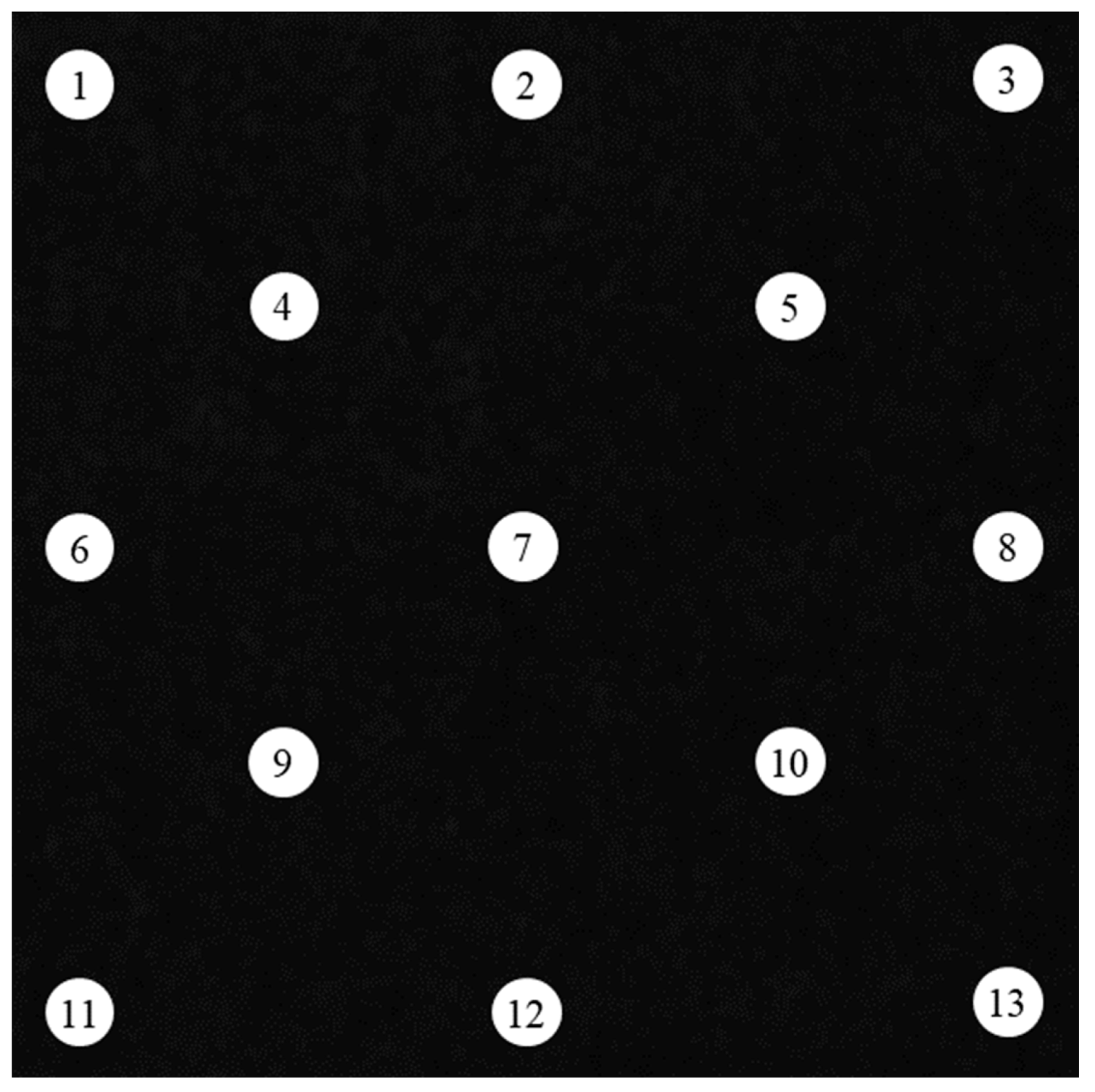
The data obtained from the detector were analyzed using ImageJ software, in which 13 sampling points numbered 1–13 of I in the detector were uniformly selected, as shown in Figure 4.
The mass attenuation coefficient μm (cm2/g) and the linear attenuation coefficient μ (cm−1) were calculated by Equations (2) and (3) [31,32]:
μ m = ln 1 S / d ρ
μ = ( 1 / d ) ln ( I 0 / I )
where d is the thickness of the composite (cm) and ρ is the density of the sample (g/cm3).
The half-value layer thickness (HVL, cm) was calculated by Equation (4) [33]:
H V L = ln 2 / μ

2.4. Material Characterization

The density of powder samples was measured by the liquid immersion method according to GB/T 5161-2014 [34]. In order to test the shielding material density, it was necessary to first measure the mass, length, width, and thickness of the sample, and then obtain its volume. Density was calculated by Equation (5):
ρ = M V
where M is the mass of the sample (g) and V is the volume of the excluded liquid or material itself (cm3).
The chemical composition of the iron-bearing dust was analyzed using an X-ray fluorescence spectrometer (ZSX Primus II, Rigaku Corporation, Tokyo, Japan). The organic elemental composition of the polyimide resin powder was determined using an organic elemental analyzer in CHN/O mode (Vario MACRO cube, Elementar, Langenselbold, Germany).

3. Results and Discussion

3.1. Effect of Iron-Bearing Dust Addition on Shielding Performance

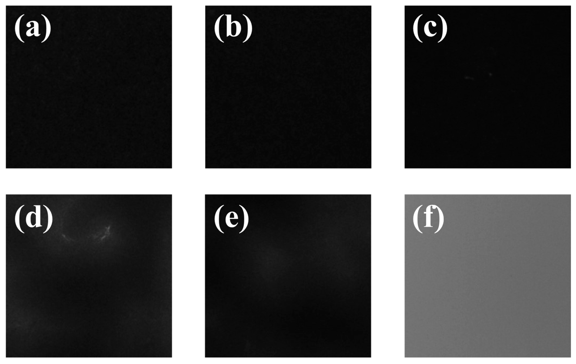
Shielding materials I-0, I-70, I-75, I-80, I-90, and I-95 were tested under conditions of a tube voltage of 55 kVp and a tube current of 2 mA. Their X-ray test results and shielding percentage when the material thickness was 3 mm are shown in Figure 5 and Figure 6a. The increase or decrease in the number of photons accepted by the flat detector can be analyzed by the change in blackness, as shown in Figure 5. I-0 had the least blackness and the highest number of photons accepted, so its shielding performance was the lowest. The blackness of I-95 was the highest, and its shielding performance was also the highest. Through the comprehensive analysis of six pictures of composite shielding materials under the same tube voltage and tube current conditions. The results show that, with an increased amount of iron-bearing dust added to the flat detector, there was an increase in blackness as the number of accepted photons decreased, so the shielding performance increased.
As shown in Figure 6a, the X-ray shielding percentage of the materials increased gradually with the addition of iron-bearing dust. The shielding percentage for the polyimide resin sheet without the addition of iron-bearing dust is only 10.83%, compared to the shielding material with the addition of iron-bearing dust, which exceeds 75%, with I-95 showing the highest shielding percentage of 93.00%. Images of the mass attenuation coefficient (μm) and half-value layer thickness (HVL) of the shielding material at a tube voltage of 55 kVp and a tube current of 2 mA are shown in Figure 6b,c. With the addition of iron-bearing dust, the mass attenuation coefficient of the shielding material gradually increases, and the maximum can reach 0.0238 cm2/g. However, the half-value layer thickness of the shielding material gradually decreases with the addition of iron-bearing dust, and reaches a minimum value of 0.68 mm. I-0 without adding iron-bearing dust filler, as shown in Figure 5 and Figure 6, its blackness, shielding percentage and mass attenuation coefficient are much lower than other shielding materials, while its half-value layer thickness shows the opposite condition. Therefore, iron-bearing dust as a filler plays a major role in the X-ray shielding process, and its shielding rate is much higher than that of the matrix. As shown in Table 2 and Figure 6a, with the addition of iron-bearing dust, the measured shielding rate and density of the shielding material are increasing, while the thickness of the material is decreasing. According to Equation (2), it can be seen that the mass attenuation coefficient increases with the increase in the material shielding rate and density, and decreases with the increase in material thickness. Therefore, the amount of iron-bearing dust added will affect the shielding rate, thickness, and density of the material, and is proportional to the change in the mass attenuation coefficient of the shielding material. According to Equation (3), the linear attenuation coefficient is related to the shielding efficiency and thickness of the shielding material. In the shielding material, as the amount of iron-bearing dust increases, its shielding efficiency increases and its thickness decreases, so its linear attenuation coefficient decreases accordingly. In addition, according to the Equation (4), the half-value layer thickness of the shielding material is inversely proportional to its linear attenuation coefficient, so the half-value layer thickness of the shielding material decreases with the increase in the amount of iron-bearing dust.

3.2. Effect of Tube Voltage on Shielding Performance

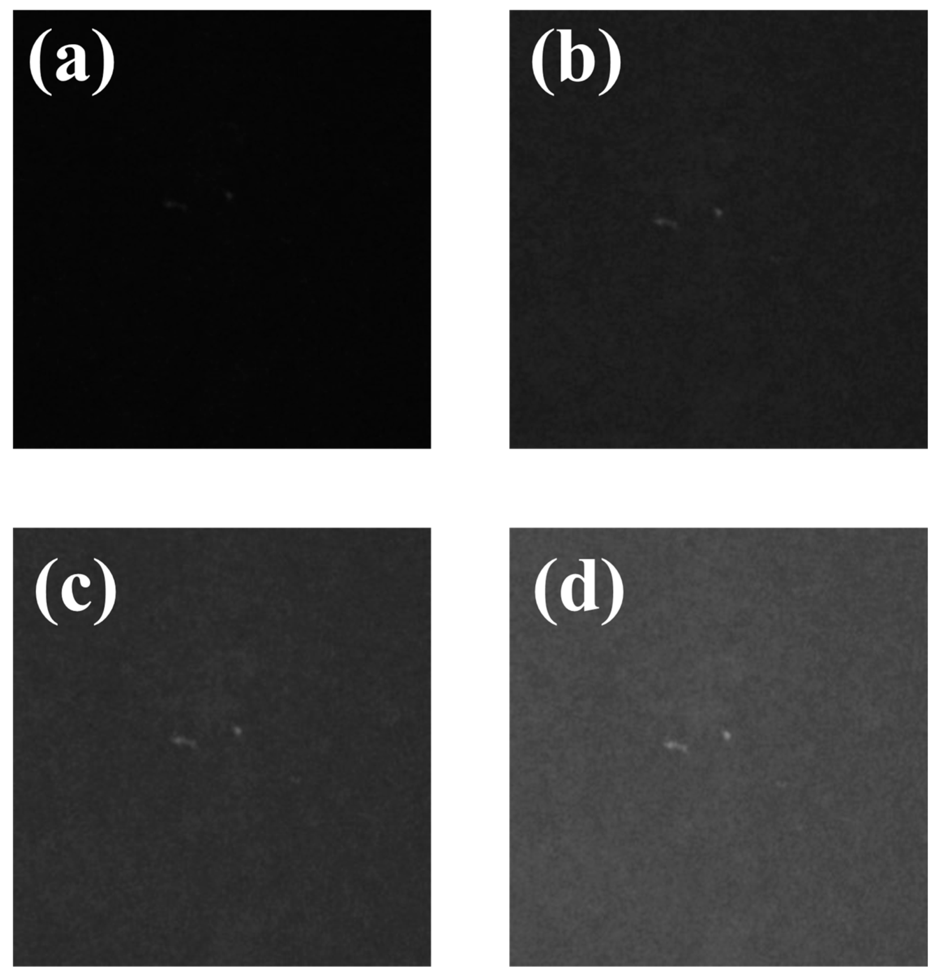
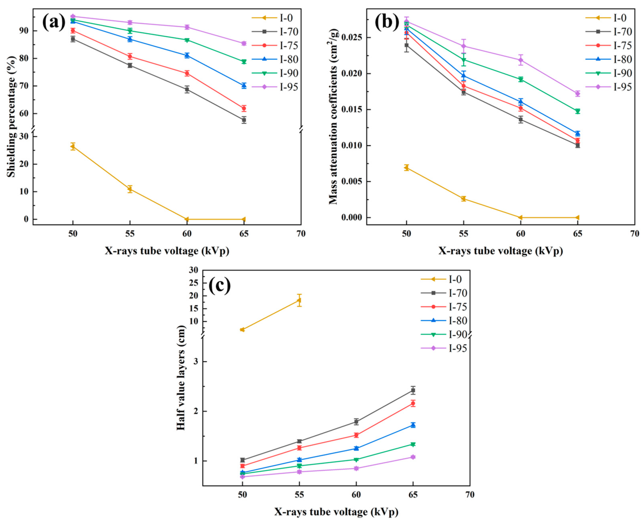
Figure 7 shows the situation where the X-ray detector receives photons passing through shielding material I-80 with a fixed tube current of 2 mA and a tube voltage of 50, 55, 60, and 65 kVp. It can be found from the graphs that the blackness detected by the detector was the largest when the tube voltage was 50 kVp, and the lowest when the tube voltage was 65 kVp. The blackness decreases as the tube voltage increases, so the number of photons received by the detector and the shielding performance both decreases. Therefore, under the condition of constant current, the shielding performance of X-rays decreases gradually with an increased tube voltage. The graphs in Figure 8a,b show the shielding material at a uniform thickness of 3 cm, shielding percentage versus voltage, and the mass attenuation coefficient versus voltage. It can be seen that the shielding percentage of I-95 is the highest and that of I-0 is the lowest under the same tube voltage condition. In addition, with increasing tube voltage, the shielding performance of all six shielding materials shows a decreasing trend. Figure 8c shows the trend of the half-value layer thickness of the shielding material with the tube voltage, which shows an increasing trend with increasing tube voltage. It is particularly noteworthy that, at a tube voltage of more than 60 kVp, the X-rays passed completely through shielding material I-0, at which time its shielding percentage was 0 and the half-value thickness could not be calculated.
According to the classical radiation protection theory, the way X-rays interact with matter will change as the energy of X-rays changes. First of all, the interaction mode in the low energy region is dominated by the photoelectric effect. Secondly, in the middle energy region, Compton scattering dominates. Finally, electron pair effects dominate in the high energy region. In this experiment, when the tube current is constant, as the tube voltage increases, the energy of the X-rays generated by the generator increases, so that the shielding efficiency of the shielding material decreases. The shielding rate of the shielding material decreases, and according to Equations (2) and (3), the mass attenuation coefficient and linear attenuation coefficient of the shielding material decrease. According to Equation (4), it can be obtained that the half-value layer thickness of the shielding material increases as the linear attenuation coefficient decreases.
In addition, for shielding materials I-70 to I-95 with iron-bearing dust as filler, their shielding performance was less affected by the addition of iron-bearing dust at a lower tube voltage of 50 kVp and more affected at a higher tube voltage of 65 kVp. Furthermore, with increasing tube voltage, the shielding performance was influenced by the addition of iron-bearing dust.

3.3. Effect of Tube Current on Shielding Performance

Figure 9 and Figure 10 show the situation of photons received by the X-ray detector using shielding material I-80 and polyamide resin matrix I-0 with the tube voltage fixed at 55 kVp and the tube current at 2, 3, and 4 mA. It can be found from the graphs that the blackness detected by the detector was the largest when the tube current was 2 mA, and the lowest when the tube current was 4 mA. Therefore, the number of photons detected after passing through the two materials reached the maximum when the tube current was 2 mA, and the minimum when the tube current was 4 mA. The number of photons received by the detector decreased with increased tube current. Therefore, under the condition of constant voltage, the shielding performance of X-rays decreases gradually with increased tube current.
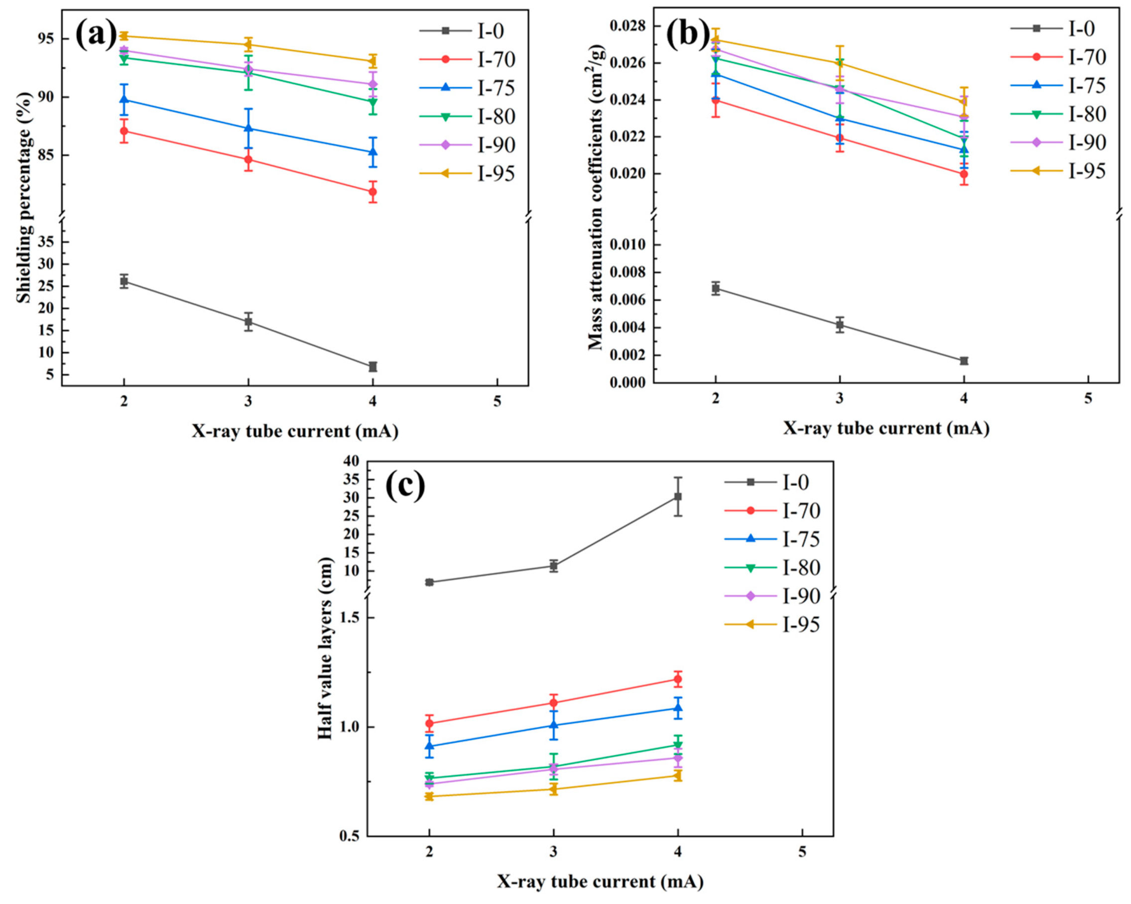
The shielding percentage and mass attenuation coefficient of the shielding materials can be visualized in Figure 11a,b. The shielding performance of all six materials tended to decrease with increased tube current. The shielding percentage and mass attenuation coefficient were the highest at the same tube current for I-95 and the lowest for I-0. Figure 11c shows the trend of the half-value thickness of shielding material with tube current; it gradually increased as the tube current increased. In addition, the shielding percentage was less affected by the addition of iron-bearing dust at different tube currents. The shielding percentage of the material with iron-bearing dust as filler had a similar trend to the change in tube current. This variation was affected quite differently by the tube current and tube voltage, and is particularly evident when comparing Figure 8a and Figure 11a.
It is similar to the effect of tube voltage on the shielding performance of shielding materials. Under the condition that the tube voltage is constant, the increase in the tube current increases the energy of the X-rays generated by the generator, thereby reducing the shielding rate of the material, thereby reducing the mass attenuation coefficient and linear attenuation coefficient of the material, and the half-value layer thickness increase. In addition, due to the larger variation in tube voltage, the effect of tube voltage on the five shielding materials containing iron-bearing dust is more obvious.

3.4. Shielding Mechanism Analysis

The WinXcom program was used to analyze the theoretical shielding properties of raw materials. The Windows version of XCOM (the Photon Cross Sections Database) can provide mass attenuation coefficients for special materials at an energy range of 0.001 MeVe100 GeV. The program is widely used to analyze the shielding performance of materials for photons (X-rays and gamma rays) [35,36,37].
Figure 12 shows the total and partial mass attenuation coefficients of the iron-bearing dust filler, polyimide resin matrix, and composite shielding materials I-70 and I-80 in the range of 45–90 kVp. As shown in Figure 12a,b, the mass attenuation coefficients of both materials decrease with increasing tube voltage. Among them, the mass attenuation coefficient of iron-bearing dust is more affected by the tube voltage, and the decline is more obvious. And the mass attenuation coefficient of iron-bearing dust is obviously higher than that of polyimide resin. This is because the mass attenuation coefficient is proportional to the atomic number, and the atomic coefficient of iron-bearing dust is much higher than that of polyimide resin.
In addition, according to the mechanism of interaction between X-rays and materials shown in Figure 12a,b, the interaction between the two raw materials and X-rays is in the range of 45–90 kVp, which are photoelectric absorption, coherent scattering, and incoherent scattering. However, the major part of the interaction of the iron-bearing dust filler is photoelectric absorption in the test tube voltage range of 50–65 kVp. And the main part of the interaction of the polyamide resin matrix is incoherent scattering. Furthermore, for iron-bearing dust, with the increase in tube voltage, the proportion of photoelectric absorption gradually decreases, and the proportion of incoherent scattering gradually increases. When the tube voltage is greater than 90 kVp, photoelectric absorption and incoherent scattering work together. While for polyimide resin at 45–90 kVp, incoherent scattering plays a major role consistently. Comparing the iron-bearing dust filler in I-70 and I-80 in Figure 12c,d. The interaction of the two shielding materials with X-rays is photoelectric absorption, coherent scattering, and incoherent scattering in the range of 45–90 kVp. And in the test tube voltage range of 50–65 kVp, their main interaction is photoelectric absorption. When it exceeds 90 kVp, their interaction becomes the joint action of photoelectric absorption and incoherent scattering. In conclusion, the mass attenuation coefficients depend on the incident photon energy and the chemical composition of materials.
And the total mass attenuation coefficients are depended on chemical composition and element content [38]. According to Akkurt [38] and EI-Khayatt [39,40], the high atomic number and high content of elements play key roles on the material shielding performance. As Table 1 shown, iron-bearing dust mainly contains O, Fe, Si, Ca, Al, and Mn, of which most elements are high-Z atomic number. And as Table S1 shown, polyimide resin powder mainly contains C, O, N, and H, of which the four elements are low-Z atomic number. So, it is noticed that high-Z atom numbers cause the shielding effect in iron-bearing dust and low-Z atom numbers cause the shielding effect in polyimide resin powder. All in all, the mass attenuation coefficients depend on the incident photon energy and the chemical composition of materials. The higher the atomic number of elements in the shielding material contains, the better shielding properties of the material will be.
Moreover, by comparison with Figure 12a, it is found that, with increased tube voltage, the change trend of the interaction of various parts is also the same as that of the filler. Therefore, the iron-bearing dust filler plays a crucial role in the shielding capacity of the composite shielding material.

4. Conclusions

In this study, X-ray shielding materials were successfully prepared by adding different amounts of iron- bearing dust as the filler to polyimide resin. Based on the testing and discussion of shielding materials, the following conclusions can be drawn:
(1)
The shielding material showed a trend of increasing shielding percentage and mass attenuation coefficient with increased addition of iron-bearing dust, tube voltage, and tube current in-tensity, while the half-value layer thickness decreased.
(2)
At a tube voltage of 55 kVp tube and current of 2 mA, shielding material I-95 had a shielding percentage of more than 95% and half-value layer thickness of less than 0.68 mm. By comparison, it was found that the shielding percentage was more significantly affected by the addition of iron-bearing dust under different tube voltage conditions than tube current conditions, and the higher the tube voltage, the greater the effect.
(3)
The interaction of the shielding material with X-rays was found to be photoelectric absorption, coherent scattering, and incoherent scattering in the range of 45–90 kVp, its main part of the interaction in the tested range of 50–65 kVp was found to be photoelectric absorption, and above 90 kVp, it was the combined action of photoelectric absorption and incoherent scattering. This is completely consistent with the interaction mode of the filler.
(4)
Iron-bearing dust used as a filler material for X-ray shielding material, realizing its clean, low-carbon, and high-value reuse. The shielding material has the advantages of high efficiency and low cost as well as a thickness and weight that are suitable for use in hospitals and other places where X-rays are generated.

Supplementary Materials

The following supporting information can be downloaded at: https://www.mdpi.com/article/10.3390/su15086682/s1. Table S1. Composition and density of polyimide resin. Figure S1. Sample diagram of radiation shielding material.

Author Contributions

Investigation, Writing—original draft, C.G. and S.Z.; Supervision, Conceptualization, Methodology, Software, Project administration, Funding acquisition, M.D.; Formal analysis, Investigation, D.X. and E.B.; Data curation, X.L.; Funding acquisition, H.Y.; Project administration, Funding acquisition, X.X. All authors have read and agreed to the published version of the manuscript.

Funding

This work was supported by the National Natural Science Foundation of China (52204417), the Fundamental Research Funds for the Central Universities (N2225036), the Postdoctoral Science Foundation of Northeastern University (20210207), and the National Key Research and Development Plan of China (2020YFC1909805). The authors thank the reviewers for their comments, which improved the manuscript.

Institutional Review Board Statement

Not applicable.

Informed Consent Statement

Not applicable.

Data Availability Statement

Not applicable.

Conflicts of Interest

The authors declare no conflict of interest.

References

  1. Gao, Q.; Xiao, X.; Suo, Z.; Long, F.; Shen, F. Thermal reactivity and flowability of pulverized coal blending with iron-bearing dust injection in blast furnace process. Case Stud. Therm. Eng. 2023, 41, 102598. [Google Scholar] [CrossRef]
  2. Fang, D. Study on Comprehensive Utilization of Iron-Containing Dust and Sludges in Iron and Steel Industry. Master’s Thesis, Shanghai Jiao Tong University, Shanghai, China, 2013. [Google Scholar]
  3. Gao, Z.-F.; Wu, Z.-J.; Liu, W.-M. Preparation and chemical looping combustion properties of Fe2O3/Al2O3 derived from metallurgy iron-bearing dust. J. Environ. Chem. Eng. 2016, 4, 1653–1663. [Google Scholar] [CrossRef]
  4. Mroz, J.; Konstanciak, A.; Warzecha, M.; Wiecek, M.; Hutny, A.M. Research on Reduction of Selected Iron-Bearing Waste Materials. Materials 2021, 14, 1914. [Google Scholar] [CrossRef] [PubMed]
  5. Szumiata, T.; Rachwał, M.; Magiera, T.; Brzózka, K.; Gzik-Szumiata, M.; Gawroński, M.; Górka, B.; Kyzioł-Komosińska, J. Iron-containing phases in metallurgical and coke dusts as well as in bog iron ore. Nukleonika 2017, 62, 187–195. [Google Scholar] [CrossRef] [Green Version]
  6. Steer, J.M.; Griffiths, A.J. Investigation of carboxylic acids and non-aqueous solvents for the selective leaching of zinc from blast furnace dust slurry. Hydrometallurgy 2013, 140, 34–41. [Google Scholar] [CrossRef]
  7. Lytaeva, T.; Isakov, A. Environmental Impact of the Stored Dust-Like Zinc and Iron Containing Wastes. J. Ecol. Eng. 2017, 18, 37–42. [Google Scholar] [CrossRef]
  8. Dou, J. Experimental Studies on Iron Recovery of Iron-Containing Dust Slime. Master’s Thesis, Inner Mongolia University of Science and Technology, Baotou, China, 8 June 2016. [Google Scholar]
  9. Fedoseeva, E.N.; Zanozina, V.F.; Zorin, A.D.; Samsonova, L.E. Preparation of Iron Oxide Pigment from Metallurgical Production Dust for Use in Construction. Metallurgist 2015, 59, 374–379. [Google Scholar] [CrossRef]
  10. Yu, Y. Production Practice of Sponge Iron Preparation of Water Atomized Iron for Steelmaking. Mod Manuf. Technol. Eq. 2016, 5, 234. [Google Scholar]
  11. Shi, Y. Study on production of sponge iron using precipitator dust. Res. Iron. Steel 2010, 38, 4. [Google Scholar]
  12. Zeng, D.; Hu, D.; Wang, G.; Qiu, J.; Qian, H.; Chen, H. The Research on Preparation of Iron-oxide Desulfurizer from Steel-making Dust. Environ. Eng. 2009, 5, 78–80. [Google Scholar]
  13. Han, H.L.; Duan, D.P.; Feng, G.S. High effective utillization of iron-containing dust and sludge in sintering process. Metal. Int. 2011, 16, 20–23. [Google Scholar]
  14. Dong, M.; Xue, X.; Liu, S.; Yang, H.; Li, Z.; Sayyed, M.I.; Agar, O. Using iron concentrate in Liaoning Province, China, to prepare material for X-Ray shielding. J. Clean. Prod. 2019, 210, 653–659. [Google Scholar] [CrossRef]
  15. Kaewjaeng, S.; Kothan, S.; Chaiphaksa, W.; Chanthima, N.; Rajaramakrishna, R.; Kim, H.J.; Kaewkhao, J. High transparency La2O3-CaO-B2O3-SiO2 glass for diagnosis x-rays shielding material application. Radiat. Phys. Chem. 2019, 160, 41–47. [Google Scholar] [CrossRef]
  16. Muthamma, M.V.; Bubbly, S.G.; Gudennavar, S.B.; Narendranath, K.C.S. Poly(vinyl alcohol)–bismuth oxide composites for X-ray and γ-ray shielding applications. J. Appl. Polym. Sci. 2019, 136, 47949. [Google Scholar] [CrossRef]
  17. Ozyurt, O.; Altinsoy, N.; Buyuk, B.; Fenerci, E. Investigation of Shielding Performance of Concretes Produced with Iron Fillings Using Betatron X-Ray Radiography. Acta Phys. Pol. 2016, 129, 829–831. [Google Scholar] [CrossRef]
  18. Rahman, L.; Bhattacharjee, S.; Islam, S.; Zahan, F.; Biswas, B.; Sharmin, N. A study on the preparation and characterization of maghemite (γ-Fe2O3) particles from iron-containing waste materials. J. Asian Ceram. Soc. 2020, 8, 1083–1094. [Google Scholar] [CrossRef]
  19. Muhammad, N.A.; Armynah, B.; Tahir, D. High transparent wood composite for effective X-ray shielding applications. Mater. Res. Bull. 2022, 154, 111930. [Google Scholar] [CrossRef]
  20. Verma, S.; Mili, M.; Bajpai, H.; Hashmi, S.A.R.; Srivastava, A.K. Advanced lead free, multi-constituent-based composite materials for shielding against diagnostic X-rays. Plast. Rubber Compos. 2020, 50, 48–60. [Google Scholar] [CrossRef]
  21. Kim, S.C. Comparison of Shielding Material Dispersion Characteristics and Shielding Efficiency for Manufacturing Medical X-ray Shielding Barriers. Materials 2022, 15, 6075. [Google Scholar] [CrossRef]
  22. Tufekci, M.M.; Gokce, A. Development of heavyweight high performance fiber reinforced cementitious composites (HPFRCC)—Part II: X-ray and gamma radiation shielding properties. Constr. Build. Mater. 2018, 163, 326–336. [Google Scholar] [CrossRef]
  23. Verma, S.; Amritphale, S.S.; Das, S. Development of Advanced, X-ray Radiation Shielding Panels by Utilizing Red Mud-Based Polymeric Organo-Shielding Gel-Type Material. Waste Biomass Valorization 2016, 8, 2165–2175. [Google Scholar] [CrossRef]
  24. Riswati; Mutmainna, I.; Rauf, N.; Tahir, D. Composites Based Ordinary Portland Cement and Fe2O3 for X-Ray Shield Applications. J. Phys. Conf. Ser. 2019, 1341, 082026. [Google Scholar] [CrossRef] [Green Version]
  25. Hussein, K.I.; Alqahtani, M.S.; Grelowska, I.; Reben, M.; Afifi, H.; Zahran, H.; Yaha, I.S.; Yousef, E.S. Optically transparent glass modified with metal oxides for X-rays and gamma rays shielding material. J. X-Ray Sci. Technol. 2021, 29, 331–345. [Google Scholar] [CrossRef] [PubMed]
  26. Zeng, W.; Qui, W.; Liu, J.; Yang, X.; Lu, L.; Wang, X.; Dai, Q. Synthesis and characterization of polyimides from metal-containing (Ba, Sr, Pb, Zn) diamines. Polymer 1995, 36, 3761–3765. [Google Scholar] [CrossRef]
  27. Zong, D. Research on Preparation of Polyimide-Based Composite and Its Radiation-Resistant Property. Master’s Thesis, Southeast University, NanJing, China, 2015. [Google Scholar]
  28. Cherkashina, N.I.; Pavlenko, V.I.; Noskov, A.V. Radiation shielding properties of polyimide composite materials. Radiat. Phys. Chem. 2019, 159, 111–117. [Google Scholar] [CrossRef]
  29. Korkut, T.; Gencel, O.; Kam, E.; Brostow, W. X-Ray, Gamma, and Neutron Radiation Tests on Epoxy-Ferrochromium Slag Composites by Experiments and Monte Carlo Simulations. Int. J. Polym. Anal. Charact. 2013, 18, 224–231. [Google Scholar] [CrossRef]
  30. Guzel, G.; Deveci, H. Physico-mechanical, thermal, and coating properties of composite materials prepared with epoxy resin/steel slag. Polym. Compos. 2017, 38, 1974–1981. [Google Scholar] [CrossRef]
  31. Dong, M.G.; El-Mallawany, R.; Sayyed, M.I.; Tekin, H.O. Shielding properties of 80TeO2–5TiO2–(15−x) WO3–xAnOm glasses using WinXCom and MCNP5 code. Radiat. Phys. Chem. 2017, 141, 172–178. [Google Scholar] [CrossRef]
  32. Dong, M.; Xue, X.; Yang, H.; Liu, D.; Wang, C.; Li, Z. A novel comprehensive utilization of vanadium slag: As gamma ray shielding material. J. Hazard. Mater. 2016, 318, 751–757. [Google Scholar] [CrossRef]
  33. Ling, T.C.; Poon, C.S.; Lam, W.S.; Chan, T.P.; Fung, K.K. Utilization of recycled cathode ray tubes glass in cement mortar for X-ray radiation-shielding applications. J. Hazard. Mater. 2012, 199–200, 321–327. [Google Scholar] [CrossRef]
  34. National Public Service Platform for Standards Information. Available online: https://std.samr.gov.cn/gb/search/gbDetailed?id=71F772D7EE19D3A7E05397BE0A0AB82A (accessed on 9 January 2023).
  35. Zhefu, L.I.; Xue, X.; Liu, S.; Yong, L.I.; Duan, P. Effects of boron number per unit volume on the shielding properties of composites made with boron ores from China. Nucl. Sci. Technol. 2012, 23, 344–348. [Google Scholar]
  36. Dong, M.; Xue, X.; Yang, H.; Li, Z. Highly cost-effective shielding composite made from vanadium slag and boron-rich slag and its properties. Radiat. Phys. Chem. 2017, 141, 239–244. [Google Scholar] [CrossRef]
  37. Chai, H.; Tang, X.; Ni, M.; Chen, F.; Zhang, Y.; Chen, D.; Qiu, Y. Preparation and properties of novel, flexible, lead-free X-ray-shielding materials containing tungsten and bismuth(III) oxide. J. Appl. Polym. Sci. 2016, 133, 10. [Google Scholar] [CrossRef]
  38. Elmahroug, Y.; Tellili, B.; Souga, C. Determination of total mass attenuation coefficients, effective atomic numbers and electron densities for different shielding materials. Ann. Nucl. Energy 2015, 75, 268–274. [Google Scholar] [CrossRef]
  39. Akkurt, I.; El-Khayatt, A.M. The effect of barite proportion on neutron and gamma-ray shielding. Ann. Nucl. Energy 2013, 51, 5–9. [Google Scholar] [CrossRef]
  40. Akkurt, I.; El-Khayatt, A.M. Effective atomic number and electron density of marble concrete. J. Radioanal. Nucl. Chem. 2012, 295, 633–638. [Google Scholar] [CrossRef]
Figure 1. Process of preparing and analyzing shielding composite.
Sustainability 15 06682 g001
Figure 2. Schematic diagram of experimental setup for X-ray radiation shielding tests.
Sustainability 15 06682 g002
Figure 3. (a) Overall image of oral cone-beam CT imaging system. (b) Image is magnified locally by imaging system. (c) Flat panel detector. (d) X-ray generator.
Sustainability 15 06682 g003
Figure 4. Schematic diagram of measurement points.
Sustainability 15 06682 g004
Figure 5. Radiography of iron-bearing dust shielding material: (a) I-70, (b) I-75, (c) I-80, (d) I-90, (e) I-95, and (f) I-0.
Sustainability 15 06682 g005
Figure 6. (a) Shielding percentage, (b) mass attenuation coefficients, and (c) half value layers of shielding materials under conditions of 55 kVp and 2 mA.
Sustainability 15 06682 g006
Figure 7. Radiography of I-80 with tube current of 2 mA and tube voltage of (a) U = 50 kVp, (b) U = 55 kVp, (c) U = 60 kVp, and (d) U = 65 kVp.
Sustainability 15 06682 g007
Figure 8. (a) Shielding percentage, (b) mass attenuation coefficients, and (c) half value layers of shielding materials at a tube current of 2 mA.
Sustainability 15 06682 g008
Figure 9. Radiography of I-80 with tube voltage of 55 kVp and tube current of (a) I = 2 mA, (b) I = 3 mA, and (c) I = 4 mA.
Sustainability 15 06682 g009
Figure 10. Radiography of I-0 with tube voltage of 55 kVp and tube current of (a) I = 2 mA, (b) I = 3 mA, and (c) I = 4 mA.
Sustainability 15 06682 g010
Figure 11. (a) Shielding percentage, (b) mass attenuation coefficient, and (c) half-value layers of shielding materials at tube voltage of 55 kVp.
Sustainability 15 06682 g011
Figure 12. Total and partial mass attenuation coefficients of (a) iron-bearing dust, (b) polyimide resin, (c) I-70, and (d) I-80.
Sustainability 15 06682 g012
Table 1. Composition and density of iron-bearing dust.
ElementFe2O3CaOSiO2MgOMnOAl2O3
Mass fraction84.75%7.05%3.51%1.38%1.15%1.027%
Table 2. Compositions (Mass ratio) and densities of the shielding composites.
SamplePolyimide ResinIron-Bearing DustThickness (cm)Density (g/cm3)
I-010006.78 ± 0.091.48 ± 0.02
I-7030703.46 ± 0.052.85 ± 0.04
I-7525753.27 ± 0.033.00 ± 0.03
I-8020802.88 ± 0.053.45 ± 0.06
I-9010902.83 ± 0.343.56 ± 0.43
I-955952.66 ± 0.193.75 ± 0.26
Disclaimer/Publisher’s Note: The statements, opinions and data contained in all publications are solely those of the individual author(s) and contributor(s) and not of MDPI and/or the editor(s). MDPI and/or the editor(s) disclaim responsibility for any injury to people or property resulting from any ideas, methods, instructions or products referred to in the content.