Abstract
A mixed-integer linear programming (MILP) model that includes reductions in neutral current, feeder energy-loss cost, customer interruption cost, and labor cost is developed to derive the optimal phase-swapping strategy to enhance the phase balancing of distribution feeders. The neutral current of the distribution feeder is reduced by the phase-swapping strategy so that the tripping of the low-energy overcurrent relay can be prevented and customer-service interruption costs and the labor cost to execute the phase-swapping works can be justified by the energy-loss reduction obtained. The novelty of the study is its derivation of the phase-swapping strategy using mixed-integer linear programming to solve the problem of the unbalance of the distribution feeders. A Taipower distribution feeder is used to derive the phase-swapping strategy to demonstrate the proposed MILP model for phase balancing. The comparison of the phase currents and neutral current before phase-swapping reveals that the three-phase balance was not only significantly improved, but that the voltage unbalance was also decreased dramatically using the proposed phase-swapping strategy.
1. Introduction
Unbalanced distribution systems increase energy losses and the risk of distribution-feeder outage because of the unexpected tripping of the low-energy overcurrent (LCO) relay. In the Taiwan Power Company’s (Taipower’s) distribution systems, the causes of phase unbalance are: (1) the asymmetrical structure of feeder networks, (2) the uneven distribution of single-phase loads, (3) variations in customer load behaviors, (4) the connectivity of open-wye, open-delta (OYD) transformers, (5) the failure of one or more capacitor units in a bank, and (6) feeder load transfer.
Figure 1 and Figure 2 show the number of occurrences during which the neutral currents of all feeders in the Kaohsiung District were >70 A for the summer and winter seasons, respectively, in 2018. One can see that the frequencies of the neutral currents that are >70 A are 30,680 and 10,812 and >100 A are 3561 and 472 for the summer and winter seasons, respectively. It is found that neutral currents increase with feeder loadings.
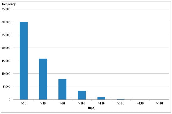
Figure 1.
Frequency of neutral currents of >70 A in all Kaohsiung District feeders in the summer season.
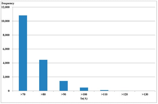
Figure 2.
Frequency of neutral currents of >70 A in all Kaohsiung District feeders in the winter season.
The main reason for the phase unbalance in Taipower’s distribution systems is the unconventional OYD transformer connection. Due to the space limitation of a sidewalk or a distribution room in a building, OYD transformers are used to serve one-phase loads as well as three-phase loads [1,2]. Figure 3 shows the connectivity of an OYD transformer with two different capacity 1-φ transformers. The load distribution between the two 1-φ transformers is very unbalanced on the primary sides of the OYD transformer, even if a 3-φ balanced load is served. With the dramatic growth in the number of single-phase residential and commercial customers served by OYD transformers, the phase unbalance problem has become more severe in Taipower’s distribution systems.
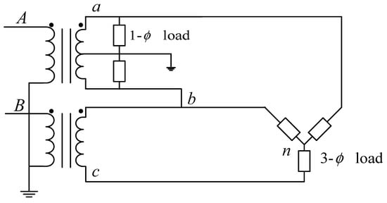
Figure 3.
Connectivity of an OYD transformer (A, B and a, b, c. are represented as the primary and secondary phases; n is represented as the neutral phase).
In addition to excessive neutral currents, an unbalanced distribution system leads to voltage unbalance. The operation of three-phase induction motors under unbalanced voltages can have serious negative effects on their performance, including overheating, decreased efficiency, and reduced output torque.
Considerable efforts have been devoted to solving the phase unbalance problems that afflict distribution systems. Some research works [3,4] incorporated phase balancing into feeder reconfiguration methods based on unbalanced distribution systems. Peng et al. [4] proposed a multi-objective dynamic reconfiguration method of minimizing the three-phase unbalance factor and number of switching times. A phase-commitment algorithm was applied to solve the unbalance issue for distributed single-phase devices. Marchesan Jr. [5] proposes a design technique to decrease voltage unbalance by choosing the correct spacing between the three phase-two wire-system overhead conductors to minimize voltage unbalance and eliminate the use of series equalization reactors or capacitors. This paper proposes a distributed optimal voltage-control and berth-allocation strategy based on mixed-integer linear programming (MILP) to mitigate voltage violations while balancing the benefits between microgrids and all-electric ships [6]. Zhou et al. develop tractable and scalable solution methods to tackle the expected objective function and chance constraints, which are reduced to a MILP problem [7]. To eliminate the potential uncertainty of recorded data, a MILP method is proposed to construct a fault diagnosis model [8]. MILP models have been proposed for distribution-network expansion planning considering reliability [9]. The water-cycle algorithm has been implemented in a case study to find the optimal phase allocation arrangement [10]. Lin et al. propose a metaheuristic algorithm to achieve energy-loss reduction through phase balancing in unbalance distribution networks [11]. The effective power electronics-based dynamic-voltage restorer has been proposed to mitigate the power quality disturbance in secondary distribution networks [12]. Malekshah et al. propose an optimal probabilistic spinning reserve quantification scheme for future smart-grid frequency enhancement considering wind generation, ESSs, thermal generating units, shiftable loads, and power-system frequency response characteristics [13]. In [14], the short-time least square prony’s (STLSP) method is based on calculating and monitoring a pertinent severity factor to prevent failure breakdowns and increase the reliability and safety of industrial facilities under unbalanced supply voltage and load variations. This paper reports the voltage-unbalance compensation performance of a three-phase inverter for a voltage unbalance compensator controlled by using the method of symmetrical components for an induction motor [15]. Some references [16,17,18,19,20] show the importance of machine learning and artificial intelligence in different engineering applications.
As feeder reconfiguration is primarily performed for load transfer and load balancing between two feeders, it cannot solve the phase unbalanced problems for distribution feeders. Phase-swapping of laterals or distribution transformers is a direct and effective method to balance a feeder. Taipower’s distribution-planning engineers already use phase swapping to balance distribution systems based on their experience and a trial-and-error approach, which is both labor-intensive and time-consuming. In this study, we propose a multi-objective mixed-integer optimization method to determine the phase-swapping strategy for the candidate laterals or distribution transformers in a distribution feeder. The objective function serves to minimize the weighted sum of the phasing unbalance index, where different normalized weights are composed of the energy-loss reduction, labor cost, and interruption cost, while executing the phase swapping of a candidate node. The novelty of the study is the development of an OYD transformer model and embedding it in the analysis of three-phase load flow. By performing the field measurement of distribution transformers for the test feeder with the developed phase identification system (PIS) [21], the lateral or transformer phasing error is identified and the corresponding attributes in the outage management system (OMS) database are corrected. The phase-swapping strategy of the unbalanced distribution feeders is derived using mixed-integer linear programming to reduce the neutral current to prevent the further tripping of supporting feeders after the non-interruptible load transfer is executed between feeders for scheduled outage or service restoration after fault contingency. The proposed method also improves the effect of voltage unbalance, to reduce electricity cost and prevent machinery damage.
In this study, the phase balancing problem is modeled as a MILP problem. Each candidate node is associated with a set of decision variables to represent its phase-swapping scheme. Kirchoff’s current law (KCL) at each node is set as linear operational constraints.
The major contributions of this study are summarized as follows:
- (1)
- The derived phase-swapping strategy not only reduces the feeder’s neutral current, unbalanced voltage, and system energy loss but also balances each service zone of a primary trunk for executing the load transfer between two feeders.
- (2)
- A multi-objective mixed-integer optimization method is then developed to optimally determine the phase-swapping strategy for laterals and distribution transformers.
- (3)
- The proposed optimal phase-swapping strategy is performed to improve the effect of voltage unbalance to reduce electricity cost and prevent machinery damage.
In this study, we develop a methodology to identify phase-swapping schemes based on the three-phase currents and the original tapping scheme at the candidate lateral for an overhead feeder or the candidate distribution transformer for an underground feeder. Section 2 presents an analysis of the three-phase currents and neutral current of an unbalanced distribution feeder. Section 3 introduces the improvements made to one of Taipower’s unbalanced feeders. A MILP model of the phase unbalance problem is proposed to derive the phase-swapping strategy in Section 4. Section 5 provides simulation results. Finally, Section 6 gives the conclusions.
2. Analysis of the Unbalanced Distribution Feeder
The collected data, including the hourly three-phase currents and neutral current from the Supervisory Control and Data Acquisition System (SCADA) of Taipower’s Distribution Dispatch Control System (DDCS), were used for the analysis of the unbalanced distribution feeder LY37. Figure 4 and Figure 5 show the daily average current profiles of the summer and winter seasons in 2018 for the test feeder LY37. Feeder LY37 serves residential and industrial customers as well as high-voltage customers in the Yong-An Industrial Park. The distributed photovoltaic generation reduces non-solar electricity demand to extremely low levels at midday because photovoltaic farms with a total capacity of 4.6 MWp are installed in the test feeder. One can see that the neutral current In increases during the summer peak-load periods. With phase current Ib being much less than Ia and Ic, the neutral current In becomes greater than the LCO setting of 70 A during the time period of 4–8 PM in the summer, and it reaches a peak value of 93.5 A at 6 PM. The hourly neutral current is even greater than the phase current Ib at 9 AM. During the winter season, the neutral current In exceeds 70 A during the time period of 6–9 PM and it reaches a peak value of 73.2 A at 8 PM.
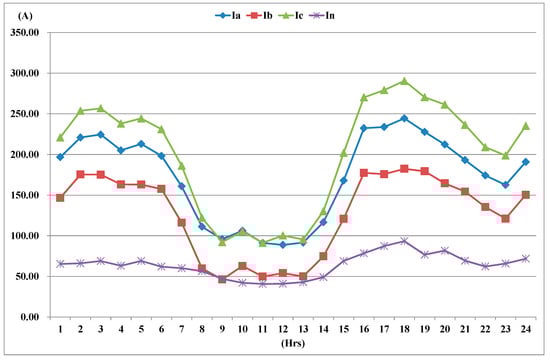
Figure 4.
Daily average current profiles of the test feeder LY37 in the summer season of 2018.
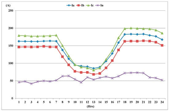
Figure 5.
Daily average current profiles of the test feeder LY37 in the winter season of 2018.
3. Improvement of the Unbalanced Feeder in the Taipower System
To solve the phase unbalancing problem of distribution feeders, the following procedures are applied to Taipower’s distribution systems and the flowchart of the phase-swapping work is illustrated in Figure 6.
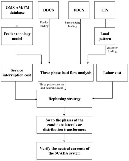
Figure 6.
Flowchart of phase-swapping work.
- Feeders with neutral currents of >70 A were selected to execute the rephrasing process.
- The facility data for the selected distribution feeders were retrieved from the OMS to identify the network configuration of distribution feeders.
- Distribution crews measured the three-phase current of each candidate lateral or distribution transformer to derive the rephrasing strategy.
- The planned outage was then scheduled to swap the phases of the candidate laterals or distribution transformers.
- The reduction in the neutral current of the rephased feeder was verified using data collected by the SCADA system.
Using a conventional trial-and-error method to derive the phase-swapping strategy for laterals and distribution transformers to improve three-phase unbalance problem is time-consuming and labor-intensive. In the research, the hourly three-phase currents and neutral current were collected by the SCADA of the Distribution Dispatching Control Center (DDCC). During an outage, the feeder load transfer is executed and the neutral current can increase dramatically. Therefore, the neutral current was defined as an outlier and was removed, as the current value was greater than three standard deviations from the mean. The facility data from the feeder was automatically converted from the OMS database to identify the feeder topology for the three-phase load flow analysis. The results of the phase currents and neutral currents of all feeder branches and distribution transformers were used for the phase-swapping strategy.
A MILP model was constructed to derive the phase-swapping strategy for the candidate laterals and distribution transformers. The normalization of multi-objective functions involves comparing and making decisions about the unbalance index of the feeder, energy loss, interruption cost, and labor cost. To represent the phase-swapping scheme for laterals or distribution transformers in the MILP model, the notation (X,Y,Z) was used to illustrate the phasing arrangement of feeder branches and transformers. Table 1 lists the valid connections in positive- and negative-sequence sets for the three-phase, two-phase, and single-phase laterals and distribution transformers. As the phase sequence is very important in the operations of a three-phase motor, maintaining the sequence after phase swapping is executed is essential. For example, a three-phase lateral with an original tap (A,B,C) can be rephased either as (B,C,A) or (C,A,B) only in a positive sequence. An OYD transformer which is connected to A and B phases (A,B,*) on the primary side can only be rephased as either C and A phases (B,*,A) or B and C phases (*,A,B) in a positive sequence.

Table 1.
Valid connections in positive- and negative-sequence sets (* is represented as no connection in the phase).
To effectively execute the phase-swapping strategy for distribution feeders, the following operational rules for the phase swapping of distribution feeders were considered in the study:
- Rule 1:
- The LCO relay of any distribution feeder that is activated >10 times a month is considered to execute the phase-swapping strategy.
- Rule 2:
- For overhead feeders, only radial lateral taps connected to primary trunk sections are considered as the candidate phase-swapping objectives.
- Rule 3:
- For underground feeders, only distribution transformers are considered as the candidate phase-swapping objectives because it is difficult to keep the same sequence for open-loop laterals.
- Rule 4:
- In addition to the reduction in the neutral current, the phase balancing of the service sections of a primary feeder must be achieved after performing the phase-swapping strategy.
- Rule 5:
- The phase sequence should be maintained to prevent the reverse rotation of three-phase motors.
4. Mathematical Formulation of the Phase Unbalance
The objective of MILP is to find the optimal phase-swapping strategy to reduce the neutral current and to maintain the phase balancing of the service sections of the primary feeder. The phasing unbalance index (PUI) at branch i, PUIi, is defined as the maximum deviation of any phase current from the average current:
where , , and are phase A, B, and C currents at branch i, and is the average phase current.
KCL is modeled by (2) before performing the phase-swapping strategy. For the distribution feeder shown in Figure 7, each phase of the lateral is tapped to the primary feeder at a node. For example, KCL at node 1 is . In general,
where and are the phase p current at the upstream branch i and at the downstream branch of the primary feeder, respectively; is the phase p current at the downstream lateral k; and k is the total number of downstream laterals at node j, which is connected with branches and .
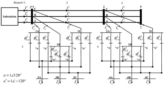
Figure 7.
Example of a distribution feeder.
4.1. MILP Formulation
To model the MILP for the phase balancing problem, the integer decision variable indicates whether or not phase p of the lateral branch l is swapped with phase w of the primary feeder. The binary integer variables must satisfy some constraints to ensure that the same phase sequence is maintained and one and only one phase of the laterals is assigned to the phase line of the primary feeder. The phase-swapping problem can be formulated into the following MILP model:
subject to
where i is any monitored branch; m is the total number of branches of the primary feeder; l is lateral l connected to branch i; k is the total number of laterals connected to branch i; PUIi is the phasing unbalance index at the monitored branch i; Ci is the summation of the energy loss cost, interruption cost, and labor cost for phase-swapping the downstream laterals that are connected to branch i; is the phase p current on branch i; and is a binary decision variable for phase w of lateral l connected to phase p of the primary feeder.
4.2. MILP Formulation Constraints
In this MILP formulation, Equations (4)–(6) represent the KCL constraints at the node that is connected with branches i and , and lateral l. The branch current must have its phase angle shifted by ±120° when phase swapping is performed from the original phase to the different phase. For instance, the phase-B current is shifted by 120° and the phase-C current is shifted by −120° in (4) when the phase-B line or the phase-C line is connected to the phase-A line ( or ). Equations (8) and (9) ensure that each phase line of a lateral is only assigned to one phase line of a primary feeder. Equations (9)–(11) ensure that the same phase sequence (positive sequence) is maintained. Equation (12) represents whether or not phase p of the lateral branch l is swapped with phase w of the primary feeder.
4.3. Feeder Phase-Swapping Cost
The total feeder phase-swapping cost can be formulated as the summation of the energy-loss cost, the customer-interruption cost, and the labor cost:
where Ci is the total cost of the phase-swapping strategy for the downstream laterals that are connected to the monitored branch i; ELCi is the energy loss cost of the phase-swapping strategy for the downstream laterals that are connected to the monitored branch i; CICi is the customer-interruption cost of the phase-swapping strategy for the downstream laterals that are connected to the monitored branch i; and LCi is labor cost of the phase-swapping strategy for the downstream laterals that are connected to the monitored branch i. To avoid different physical meanings or magnitudes of these costs, the cost space needs to be normalized using the standardization of dispersion.
4.3.1. Energy-Loss Cost (ELC)
After implementing the phase-swapping strategy derived by the MILP phase-swapping model, parts of the lateral configuration are updated. A three-phase load flow analysis is then executed to solve for the hourly system loss. In the study, the energy loss ELC can be formulated as
where is the unit energy loss cost ($0.08/kWh) and is the total energy loss.
4.3.2. Customer-Interruption Cost (CIC) [22,23]
The CIC represents the cost of an interruption in electricity service to customers as a result of performing the phase-swapping of laterals and distribution transformers, and is defined as
where n is total number of nodes affected by the phase-swapping work for the downstream laterals that are connected to branch i; ICj is the total interruption cost at node j resulting from the phase-swapping work for the downstream laterals that are connected to branch i; Cj is the unit interruption cost of node j (USD/kW); ti is the outage duration time of the phase-swapping work for the downstream laterals that are connected to branch i; and Lj is the total load demand of node j.
The planned power-outage durations for Taipower during phase-swapping works for a lateral, an OYD transformer, and a single-phase transformer are given in Table 2. The unit interruption costs Cj of the residential, commercial, and industrial customers can be formulated as follows:
where , , and are the load percentages for residential, commercial, and industrial customers, respectively, at downstream node j, which is connected with branch i; , , and are the interruption-cost functions for residential, commercial, and industrial customers, respectively.
Table 2.
Outage durations of phase-swapping work.
4.3.3. Labor Cost
The labor cost based on the man power required and the time duration for Taipower to complete the phase-swapping of laterals and distribution transformers is listed in Table 3.
Table 3.
Labor cost of phase-swapping work.
5. Case Study
Taipower’s overhead feeder LY37, shown in Figure 8, was used for a computer simulation of lateral phase swapping in this section to balance the primary feeder, to illustrate the proposed MILP-based phase-swapping strategy. The total length of the 11 kV feeder is 5.7 km to serve the mixed loadings of industrial and residential customers. It consists of three service zones (T1, T2, and T3) on the primary trunk and nine service zones on the laterals with 103 units of OYD transformers and 58 units of 1-φ transformers to provide power service to >1000 low-voltage customers and 2 high-voltage customers. The three-phase unbalance problem diminishes service reliability and increases power loss (as mentioned in Section 2) because of the usage of many single-phase and OYD transformers in the feeders. The phase-swapping strategy for laterals and distribution transformers was derived using the MILP model to reduce the neutral current and annual energy loss.
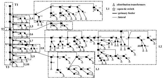
Figure 8.
One-line diagram for Feeder LY37.
Figure 9 shows the results of the three-phase currents and neutral current of the primary trunk and laterals based on three-phase load flow analysis. In Figure 9, for instance, the three-phase currents and neutral current of the lateral section L2 were Ia = 131.8 A, Ib = 85.8 A, Ic = 163.7 A, and In = 66.7 A at the peak time of 6 PM. The loading of phase B was much lower than those of phases A and B. The results illustrate the severity of three-phase unbalance for the lateral because the neutral current In is even greater than Ib.
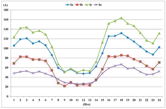
Figure 9.
Hourly phase currents and neutral current of lateral L2.
5.1. Phase-Swapping Strategy for Feeder LY37
To maintain the phase sequence and reduce labor costs, only radial taps connected to a primary trunk section were considered as the candidate phase-swapping locations for the overhead feeder LY37. Table 4 illustrates the phase-swapping strategy for the candidate laterals identified by performing the MILP optimization algorithm. Figure 10 shows the neutral currents of the test feeder before and after performing the MILP phase-swapping methodology, based on solving for the feeder loading at 6 PM, in Figure 4, using three-phase load flow analysis. The neutral current decreased from 93 A to 25 A after performing the phase-swapping of laterals L1, L2, and L5 from (A,B,C) to (C,A,B) and (B,C,A), and (B,C,A), respectively. In comparison to the phase currents in Figure 4, the phase current Ic decreased while the phase currents Ia and Ib both increased after phase-swapping laterals L1, L2, and L5.
Table 4.
Proposed phase-swapping strategy for feeder LY37.
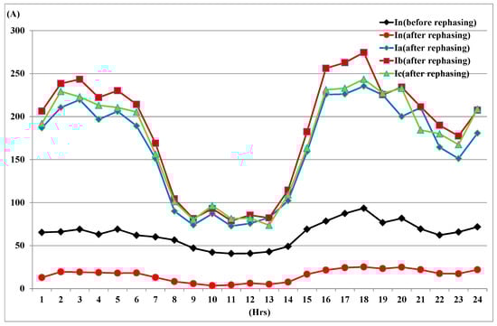
Figure 10.
Three-phase currents and neutral current before and after phase swapping.
The reduction in feeder power loss was solved by three-phase load flow analysis for the test feeder before and after the phase swapping of the laterals. Figure 11 shows the loss percentage of the test feeder before and after phase swapping. The peak power loss decreased from 3.26% to 1.92% at 6 PM. The average daily power loss reduced from 2.8% to 1.8% by phase swapping three laterals.
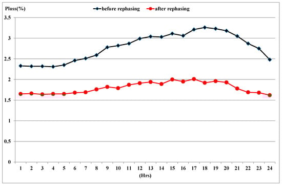
Figure 11.
Power loss percentage of the test feeder before and after phase swapping.
Table 5 illustrates the cost versus benefits in terms of the reduction in annual energy-loss cost, customer-interruption cost, and labor cost to perform the phase-swapping works for the test feeder. The proposed phase-swapping strategy achieves the total energy loss cost of USD 23,400 and the customer-service-interruption and labor costs are USD 6700 and USD 660.
Table 5.
Cost–benefit analysis for the phase-swapping feeder.
5.2. Effects on a Three-Phase Induction Motor in the Unbalanced Case
Induction motors are widely used by industrial customers of the test feeder. The supplied voltage can cause ill effects in induction motors because of the unbalanced distribution feeder. To study how the unbalanced scenario affects an induction motor, we discuss the results of voltage unbalance before and after phase swapping the test feeder. The voltage unbalance factor (VUF) is defined as the ratio of the negative-sequence voltage component to the positive-sequence voltage component [24]:
where V1 and V2 are obtained using symmetrical component transformation.
The industrial customer with a three-phase 7.5 hp induction motor connected to an OYD transformer at Bus 332 in Figure 8 was selected for computer simulation to investigate the effects of an unbalanced voltage supply before and after implementing the phase-swapping strategy. The positive- and negative-sequence voltages were solved using symmetrical component transformation after executing a three-phase load flow analysis based on the proposed phase-swapping strategy. Table 6 lists the VUFs at the primary and secondary sides of the OYD transformer at Bus 332.
Table 6.
VUF at Bus 332 before and after phase swapping.
The NEMA standard [25] states that, once unbalance reaches 5%, the temperature begins to rise so quickly that protection from damage becomes impractical. From this analysis, the VUF of the secondary side of the OYD transformer reaches 7.33% before phase-swapping. As per the NEMA guidelines, operating a motor for any length of time at a voltage unbalance of >5% is not recommended because the temperature begins to rise too quickly and the loss increases when the VUF reaches 5% based on the derating curve. By implmenting the MILP methodology, the over-neutral-current problem was solved successfully and VUF decreases significantly after the phase-swapping of three laterals.
6. Discussion
The phasing arrangement project with the proposed phase-swapping strategy has been implemented in the feeders of Taipower distribution systems and the field work for the phase-swapping of laterals and distribution transformers have been completed. The input data, including feeder topology and the feeder and customer loadings, were created automatically to support the phase-swapping strategy. In comparison with the traditional trial-and-error method used by Taiopower, the proposed phase-swapping algorithm can reduce labor-intensive and time-consuming work for distribution engineers.
7. Conclusions
The three-phase unbalance problem for feeders is becoming more and more important in Taipower’s distribution systems because solving it can improve power quality and reduce energy loss with minimal costs. The three-phase currents and neutral current were collected from the SCADA of Taipower’s DDCC and the attributes of distribution facilities were retrieved from the OMS database to develop the distribution system topology model and to automatically create the input data file for the three-phase load flow.
A MILP formulation which includes reductions in the phasing unbalance index, feeder energy-loss cost, customer-interruption cost, and labor cost was proposed to derive the optimal phase-swapping strategy for laterals and distribution transformers to balance distribution feeders. A Taipower distribution feeder was used to demonstrate the proposed MILP model for phase balancing. The neutral current decreased from 93 A to 25 A and the average daily power loss was improved from 2.8% to 1.8%. The phase unbalance of the Taipower’s feeder was improved significantly in comparison with the phase currents and neutral current before phase-swapping. In addition to solving the over-neutral-current problem, VUF decreased dramatically, from 7.33% to 2.31%, after the phase-swapping of three laterals to reduce electricity cost and prevent machinery damage.
Most photovoltaic systems which are connected directly to the distribution systems in Taiwan are small- or medium-sized. The power that is generated by PV systems exceeds the load, which has caused the problem of reverse power flow to the distribution substation. Reverse power flow as well as the controls of the smart inverters usually present in power distribution systems were not considered. Further work will consider these aspects as well as the theoretical and practical consequences of the phase-swapping strategy.
Author Contributions
Conceptualization, C.-H.L. and C.-S.C.; methodology, C.-S.L.; software, C.-H.L. and T.-T.K.; validation, C.-H.L. and T.-T.K.; writing—original draft preparation, C.-H.L.; writing—review and editing, T.-T.K. All authors have read and agreed to the published version of the manuscript.
Funding
This research was funded by the National Science and Technology Council under the Contract MOST 111-2221-E-992-035.
Institutional Review Board Statement
Not applicable.
Informed Consent Statement
Not applicable.
Data Availability Statement
Not applicable.
Acknowledgments
Authors of this research express a gratitude to Taiwan Power Company for materials used for experiments.
Conflicts of Interest
Authors declare that they do not have any competing financial, professional or personal interests from other parties.
References
- Huang, J.; Tai, Y.; Liu, Z.; Su, F.; Gu, H. Application of Bird-Mating Optimization to Phase Adjustment of Open-wye/Open-delta Transformers in a Power Grid. In Proceedings of the 2015 IEEE International Conference on Industrial Technology (ICIT), Seville, Spain, 17–19 March 2015. [Google Scholar]
- Santoso, S.; Dugan, C. Experiences with the New Open-wye/Open-delta Transformer Test Cases for Distribution System Analysis. In Proceedings of the 2005 IEEE Power Engineering Society General Meeting, San Francisco, CA, USA, 12–16 June 2005. [Google Scholar]
- Peng, C.; Xu, L.; Gong, X.; Sun, H.; Pan, L. Molecular Evolution Based Dynamic Reconfiguration of Distribution Networks with DGs Considering Three-Phase Balance and Switching Times. IEEE Trans. Ind. Inform. 2019, 15, 1866–1876. [Google Scholar] [CrossRef]
- Fahim, M.; Hassan, E.; Najjar, E. Single Phase Load Balancing in a Three Phase System at Distribution and Unit Level. In Proceedings of the 2018 IEEE International Conference on Industrial Technology (ICIT), Lyon, France, 20–22 February 2018. [Google Scholar]
- Marchesan, G.; Oliveira, L.; Cardoso, G.; Ramos, B.; Kraulich, L.; Mazzorani, L.; Silveira, F. Three-Phase-Two-Wire Rural Distribution Network: Influence of Design Characteristics on Voltage Unbalance. IEEE Trans. Power Deliv. 2023, 38, 620–630. [Google Scholar] [CrossRef]
- Sun, X.; Qiu, J.; Tao, Y.; Yi, Y.; Zhao, J. Distributed Optimal Voltage Control and Berth Allocation of All-Electric Ships in Seaport Microgrids. IEEE Trans. Smart Grid 2022, 13, 2664–2674. [Google Scholar] [CrossRef]
- Zhou, A.; Zhai, H.; Yang, M.; Lin, Y. Three-Phase Unbalanced Distribution Network Dynamic Reconfiguration: A Distributionally Robust Approach. IEEE Trans. Smart Grid 2022, 13, 2063–2074. [Google Scholar] [CrossRef]
- Tang, Z.; Peng, Z.; Liang, R.; Peng, N.; Wang, C. Multi-Source Data-Cooperated Neutral Low-Resistance Grounding Cable Grid Faulty Segment Identification. IEEE Trans. Power Syst. 2022, 37, 1413–1424. [Google Scholar] [CrossRef]
- Jooshaki, M.; Abbaspour, A.; Fotuhi-Firuzabad, M.; Muñoz-Delgado, G.; Contreras, J.; Lehtonen, M.; Arroyo, J. An Enhanced MILP Model for Multistage Reliability-Constrained Distribution Network Expansion Planning. IEEE Trans. Power Syst. 2022, 37, 118–131. [Google Scholar] [CrossRef]
- Eam, D.; Vai, V.; Eng, S.; You, L. Optimizing Phase Allocation Arrangement for a Rural LVAC Distribution System: A Case Study in Cambodia. In Proceedings of the 2022 4th International Conference on Electrical, Control and Instrumentation Engineering (ICECIE), KualaLumpur, Malaysia, 26–26 November 2022. [Google Scholar]
- Lin, C.; Huang, T.; Chih, C.; Yao, C.; Li, T.; Ma, C. Comparisons of Energy Loss Reduction by Phase Balancing in Unbalance Distribution Networks via Metaheuristic Algorithms. In Proceedings of the 2020 International Conference on Pervasive Artificial Intelligence (ICPAI), Taipei, Taiwan, 3–5 December 2020. [Google Scholar]
- Ogunboyo, T.; Tiako, R.; Davidson, E. Effectiveness of Dynamic Voltage Restorer for Unbalance Voltage Mitigation and Voltage Profile Improvement in Secondary Distribution System. Can. J. Electr. Comput. Eng. 2018, 41, 105–115. [Google Scholar] [CrossRef]
- Malekshah, S.; Alhelou, H.; Siano, P. An Optimal Probabilistic Spinning Reserve Quantification Scheme Considering Frequency Dynamic Response in Smart Power Environment. Int. Trans. Electr. Energy Syst. 2021, 31, e13052. [Google Scholar] [CrossRef]
- Alloui, A.; Laadjal, K.; Sahraoui, M.; Cardoso, M. Online Interturn Short-Circuit Fault Diagnosis in Induction Motors Operating Under Unbalanced Supply Voltage and Load Variations, Using the STLSP Technique. IEEE Trans. Ind. Electron. 2022, 70, 3080–3089. [Google Scholar] [CrossRef]
- Katsuki, T.; Yamakawa, I.; Imakiire, A.; Matsumoto, S. Voltage Compensation Performance of the Voltage Unbalance Compensator Using the Method of Symmetrical Components. In Proceedings of the 2022 International Power Electronics Conference (IPEC-Himeji 2022-ECCE Asia), Himeji, Japan, 15–19 May 2022. [Google Scholar]
- Moustafa, B.; Elsheikh, A. Predicting Characteristics of Dissimilar Laser Welded Polymeric Joints Using a Multi-Layer Perceptrons Model Coupled with Archimedes Optimizer. Polymers 2023, 15, 233. [Google Scholar] [CrossRef] [PubMed]
- Elsheikh, H. Applications of Machine Learning in Friction Stir Welding: Prediction of Joint Properties, Real-time Control and Tool Failure Diagnosis. Eng. Appl. Artif. Intell. 2023, 121, 105961. [Google Scholar] [CrossRef]
- Elsheikh, H. Bistable Morphing Composites for Energy-Harvesting Applications. Polymers 2022, 14, 1893. [Google Scholar] [CrossRef] [PubMed]
- Elsheikh, H.; El-Said, S.; Elaziz, A.; Fujii, M.; El-Tahan, R. Water Distillation Tower: Experimental Investigation, Economic Assessment, and Performance Prediction Using Optimized Machine-learning Model. J. Clean. Prod. 2023, 388, 135896. [Google Scholar] [CrossRef]
- Khoshaim, B.; Moustafa, B.; Bafakeeh, T.; Elsheikh, H. An Optimized Multilayer Perceptrons Model Using Grey Wolf Optimizer to Predict Mechanical and Microstructural Properties of Friction Stir Processed Aluminum Alloy Reinforced by Nanoparticles. Coatings 2021, 11, 1476. [Google Scholar] [CrossRef]
- Chen, S.; Ku, T.; Lin, C. Design of Phase Identification System to Support Three-Phase Loading Balance of Distribution Feeders. IEEE Trans. Ind. Appl. 2012, 48, 191–198. [Google Scholar] [CrossRef]
- Chen, S.; Lin, H.; Chuang, J.; Li, S.; Huang, Y.; Huang, W. Optimal Placement of Line Switches for Distribution Automation Systems Using Immune Algorithm. IEEE Trans. Power Syst. 2006, 21, 1209–1217. [Google Scholar] [CrossRef]
- Liang, C.; Wang, P.; Han, X.; Qin, W.; Billinton, R.; Li, W. Operational Reliability and Economics of Power Systems with Considering Frequency Control Processes. IEEE Trans. Power Syst. 2017, 32, 2570–2580. [Google Scholar] [CrossRef]
- Dash, N.; Sahu, S.; Panigrahi, K. Effect and Analysis of Unbalanced Voltage on Induction Motor Torque. In Proceedings of the 2018 International Conference on Recent Innovations in Electrical, Electronics & Communication Engineering (ICRIEECE), Bhubaneswar, India, 27–28 July 2018. [Google Scholar]
- Standard MG1-2003; ANSI/NEMA, Motors and Generators. Part 14 and 20. NEMA: Rosslyn, VA, USA, 2004.
Disclaimer/Publisher’s Note: The statements, opinions and data contained in all publications are solely those of the individual author(s) and contributor(s) and not of MDPI and/or the editor(s). MDPI and/or the editor(s) disclaim responsibility for any injury to people or property resulting from any ideas, methods, instructions or products referred to in the content. |
© 2023 by the authors. Licensee MDPI, Basel, Switzerland. This article is an open access article distributed under the terms and conditions of the Creative Commons Attribution (CC BY) license (https://creativecommons.org/licenses/by/4.0/).