Article

Investigation of a Compound Parabolic Collector with a Flat Glazing

by
Evangelos Bellos
*,
Dimitrios N. Korres
and
Christos Tzivanidis
Department of Thermal Engineering, School of Mechanical Engineering, National Technical University of Athens, 15780 Athens, Greece
*
Author to whom correspondence should be addressed.
Sustainability 2023, 15(5), 4347; https://doi.org/10.3390/su15054347
Submission received: 2 February 2023 / Revised: 23 February 2023 / Accepted: 26 February 2023 / Published: 28 February 2023

Abstract

:
The compound parabolic concentrator is a promising technology for efficient solar irradiation exploitation at low- and medium-temperature levels. This collector type can be used in a series of applications, such as solar cooling, desalination, and industrial process heat applications. This work presents a novel compound parabolic concentrator that presents satisfying efficiency and low cost due to the use of flat glazing and not an evacuated tube receiver. More specifically, the goal of the present investigation is based on the energy and exergy analysis of a compound parabolic collector with flat glazing, which has a concentration ratio of 2.81. The collector is examined thermally and exegetically, aiming to calculate the efficiency of different operating inlet temperatures. Moreover, the solar unit is studied by a developed computational fluid dynamics model in the SolidWorks Flow Simulation tool. Emphasis is given to the calculation of the convection losses of the receiver tube with the internal air inside the collector. The heat convection coefficient is calculated, and the distribution of the thermal losses, convection, and radiation is presented. Furthermore, the temperature levels of the absorber, the cover glass, and the top thermal loss coefficient are found. The thermal efficiency of the solar unit was 77.4% for inlet temperature at 10 °C and 32.6% for inlet temperature at 110 °C. It was calculated that the maximum exergetic performance of the solar unit is 10.19% for operation at 90 °C, while the thermal efficiency for this case is 41.57%. Additionally, the temperature distributions for different cases are included in the present work.

1. Introduction

Compound parabolic concentrator (CPC) belongs to the family of concentrating solar systems with a low concentration ratio, and thus, they can be characterized as non-imaging systems [1]. They present concentration ratios from 1.1 of up to 5 [2], while the development of a higher concentration ratio makes this technology tend to the parabolic trough collectors. China is the lead research contributor to CPC technology with 23% of the worldwide literature studies [3]. The CPC operates at low- and medium-temperature levels, usually up to 150 °C or 200 °C [2], and it was initially suggested by Winston [4]. It can be used in numerous applications in the building and industrial sectors, such as solar cooling [5], desalination [6], power production [7], and industrial heat production [8]. However, this collector has not managed to be widely used because it faces high competition with other solar concentrating systems, such as the parabolic trough collector [9] and the linear Fresnel reflector [10]. Thus, there is a need to develop the CPC of the new generation, which can be less expensive than the other concentrating systems and with lower complexity to provide new benefits in the solar market.
The usual CPC consists of a linear concentrator and an evacuated tube that can operate at medium temperature with reduced thermal losses. Practically, the tubular receiver has been found to be the most effective choice among others [11]. Additionally, the CPC can be used as a secondary concentrator in linear Fresnel reflector designs [12] or in parabolic trough collectors [13]. Usually, the CPC operates with water, an ethylene glycol/water mixture, or thermal oils. The CPC operation needs sun tracking for achieving high performance, while there are no tracking designs with a system of low-concentration ratio or asymmetrical reflectors [14].
The literature includes numerous numerical and experimental studies regarding the aforementioned collector type. Ma et al. [15] examined experimentally a CPC with an evacuated tube that has an experimental novel selective coating. They examined their system for operating temperatures up to 150 °C. According to the results, the system efficiency was found in the range of approximately 40% to 60%. Liu et al. [16] examined an all-glass CPC with an evacuated tube collector for steam generation, and they reported maximum efficiency values of up to 51%. In another investigation, Korres and Tzivanidis [17] examined a U-type mini CPC with an evacuated receiver. They reported the efficiency of the suggested design is higher than other CPC designs in the literature by finding thermal efficiency of up to 80% in low operating temperatures. In another work, Bellos et al. [18] optimized the geometry of a CPC with an evacuated tube and examined it thermally. They concluded the operation with pressurized water leads to increased thermal efficiency compared to the use of thermal oil. In another work of this research team [19], it was concluded the application of nanofluids can improve the performance of a CPC.
The idea of using a receiver that acts as a tank inside the CPC has been examined experimentally by Souliotis and Tripanagnostopoulos [20]. They practically used flat glazing over the CPC cavity, and they used a receiver tube of a high diameter for storing a significant amount of water inside. They found this design can be a competitive one with the flat plate collectors. In another work of the same research team [21], the design with two internal tanks was studied. Different configurations were studied, and they concluded this design is very efficient during the day with a satisfactory performance at night. Regarding the optimal location of the stable systems, it was concluded the east–west direction is the more efficient choice than the south–north direction [22]. Furthermore, Tripanagnostopoulos and Souliotis [23] concluded the exploitation of an asymmetrical reflector is a more efficient choice compared to the use of a symmetric reflector. The use of an asymmetric reflector with an evacuated tube has been investigated by Korres et al. [24]. They evaluated the use of a cavity receiver and a U-tube conventional receiver. They concluded the cavity absorber design inside the evacuated tube is the best solution. Recently, Zhang et al. [25] designed an asymmetrical CPC with the help of a 3-D printer. They found the suggested asymmetrical design can operate for more hours per year compared to the symmetrical one.
Moreover, the use of CPC has been found to be a more efficient choice compared to the use of an evacuated tube collector for a solar cooling system in Egypt. More specifically, the CPC was found to lead to 94% solar coverage, while it was 66% for the evacuated tube collector [26]. The use of a CPC field has been also used for producing ice with a water/NH3 absorption chiller [27]. Another option is the incorporation of a compound parabolic concentrator with photovoltaic cells for increasing the solar concentration on the cell. This fact has been examined with a concentration ratio of about 2 and a half-acceptance angle of 30° [28].
The previous analysis shows significant interest in the CPC. The present work suggests an interesting CPC configuration that presents low cost and a low-complexity level due to the lack of an evacuated tube. Practically, the suggested unit has a bare receiver tube without a cylindrical cover in a CPC cavity with a flat glass cover. This design can operate in low temperatures, and it has been examined up to 110 °C inlet temperature with pressurized water at 5 bar to avoid evaporation. There is internal heat convection between the absorber tube and the inside air, which is examined in detail. More specifically, emphasis is given to the calculation of the internal heat convection coefficient between the absorber and the air. The analysis is a computational fluids dynamic investigation with the SolidWorks Flow Simulation software [29]. The results of this analysis clearly show the thermal and exergy behavior of the present design, while critical aspects of the present collector are also illustrated, such as the temperature distribution over the internal and external surfaces.

2. Material and Methods

2.1. The Designed CPC with Flat Glazing

The present system is a low-cost concentrating collector with a mean concentrating ratio of around 2.8 and a half-acceptance angle of 53°. The geometry of the CPC is an optimized one, and it has been taken from our previous work in Ref. [18]. The main dimensions and the data of the present solar unit are included in Table 1.
The collector has a cylindrical absorber with a selective coating, while there is no cylindrical cover. The cover in the present system is a flat glass that closes the collector and keeps the air inside the collector. The capture of the air leads to a low-cost design without complexity due to the lack of the evacuated tube, while the heat losses are restricted because the air is an enclosure and there is no leakage with the ambient. Moreover, the present system has an external insulation of 2 cm with glass wool, which reduces the edge thermal losses. Figure 1 exhibits the solar collector, which consists of the outer insulation, the CPC reflector, the absorber tube, and the flat glazing. The aperture of the module is 0.3 m2, which indicates that in a real application, many modules must be combined to achieve the proper thermal production capacity. The working fluid in the present work is pressurized water of 5 bar, aiming to keep it in the liquid phase during all the simulations. The present design is an alternative choice in the CPC family, aiming to operate efficiently without an evacuated tube collector to reduce the cost and complexity of the system.

2.2. Basic Mathematical Formulation Part

The following mathematical formulation part includes the main parameters and evaluation indexes used in the present simulation work.
The solar energy in the system can be found as:
Q solar = A a G
The collecting area is the product of the aperture dimensions as below:
A a = L W
The useful heat production is determined as:
Q u = m c p T out T in
The optical efficiency expression is the next:
η opt = Q abs Q solar
The heat losses of the unit can be calculated as:
Q loss , total = η opt Q sol Q u
The total thermal losses are separated into the edge and the top losses:
Q loss , total = Q loss , edge + Q loss , top
The top heat loss coefficient of the system can be written as:
U t = Q loss , top A a T c T am
The thermal efficiency can be found as:
η th = Q u Q solar
The exergy efficiency of the unit can be calculated as below by applying the Petela model [30] for estimating the solar exergy flow, neglecting the pressure drop which is too low in the present system [31]:
η ex = Q u m c p T am ln T out T in Q solar 1 4 3 T am T sun + 1 3 T am T sun 4
In the previous formula, the temperature levels are used in Kelvin units, and the mean sun temperature is selected at 5770 K. The exergy efficiency is a valuable index that shows the possibility of work extraction by ideally exploiting the produced thermal energy from the collector. It evaluates both the produced heat quantity and its temperature level. Hence, this index is ideal for evaluating the possibility of using the present collector on a system that includes other thermodynamic cycles (e.g., power or refrigeration cycles).

2.3. Details of the Simulation Process

The present simulation study has been developed with the SolidWorks Flow Simulation tool (Dassault Systèmes SolidWorks Corporation, Waltham, MA, USA) [29]. This tool can conduct optical, thermal, and flow studies simultaneously, and it is an ideal choice for the simulation of solar concentrating systems. The following methodology for the model developed has also been described in previous studies [18,19] and thus, it will be given briefly below.
The basic boundaries conditions are the following:
(A)
The solar irradiation on the collector aperture is selected at 800 W/m2.
(B)
The solar angle is equal to zero, and thus, the solar rays are vertical to the collector opening.
(C)
The inlet temperature in the system is chosen to vary from 10 °C up to 110 °C.
(D)
The ambient temperature was selected at 10 °C.
(E)
The heat convection coefficient with the environment was chosen at 10 W/m2K [32].
(F)
The mass flow rate of the pressurized water was selected at 0.01 kg/s in the inlet.
(G)
The outlet pressure was chosen at 5 bar.
Table 2 summarizes the basic input parameters of the present model. The copper absorber tube was chosen to be selective, and the cover is made of glass material, while the insulation is glass wool. The air inside the cavity exchanges heat with the absorber and the reflecting surface with natural convection. Practically, the air moves inside the cavity due to temperature variation, which plays a critical role in the present modeling. The system operates with a mass flow rate of 0.01 kg/s, which leads to a laminar flow regime in all the studied scenarios. Additionally, the thermal properties of the water during the simulation are not constant, but they vary according to the water temperature level.
The present tool makes possible the calculation of critical parameters. The most important parameters that are taken as simulation outputs are the following: water bulk outlet temperature, average absorber temperature, average glass temperature, heat convection coefficient between the absorber and inside air, total thermal losses, top thermal losses, and edge thermal losses.
The optical analysis has been conducted with a total number of rays at 107, which is a sufficient number that was defined after the preliminary analysis. The final model was discretized properly using the mesh tool of SolidWorks, and finally, a total number of cells of around 2 million was selected after some trials with different meshes. Verification results of the present flow model inside the absorber tube can be found in our previous work [19]. Moreover, the results regarding the optical efficiency calculation and the impact of the solar angles on the collector performance have been previously given in Ref. [18]. Additionally, this work includes details regarding the reflector geometry and the absorber tube geometry because it was a preliminary work that supports the optical and design parts of the present study. Regarding the validity of the present work, verification results of thermal performance for a similar CPC with an evacuated tube collector have been published in Ref. [18], while the flow verification results of this similar design have been published in Ref. [19]. Thus, it is obvious the SolidWorks Flow Simulation tool is a proper tool for conducting investigations of CPC systems. Additionally, it is useful to add that verification evidence for the followed methodology has been presented in other studies, such as Ref. [17] for a mini-CPC and Ref. [24] for an asymmetric CPC.
The inlet temperature of the fluid was examined from 10 °C up to 110 °C with a step of 20 °C. The scope of the present analysis is to study the system in various operating temperature scenarios and in a reasonable range and the development of the thermal efficiency curve. Hence, the collector performance can be evaluated for different possible operating scenarios and applications.

3. Results and Discussion

3.1. Thermal and Exergy Performance Analysis

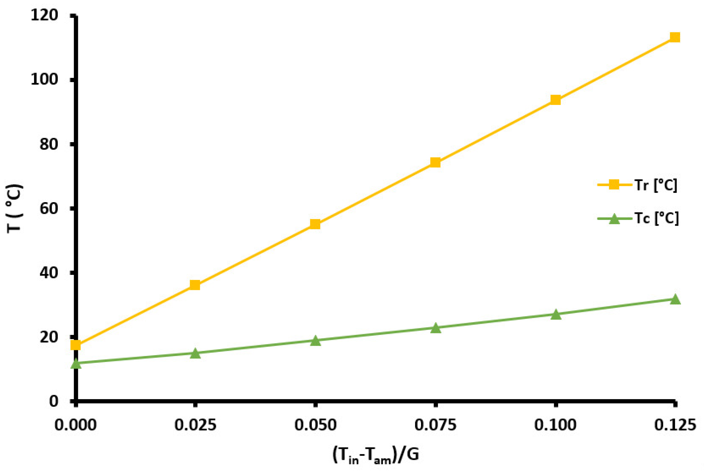
The examined solar unit is studied for different inlet temperatures aiming to calculate the solar unit’s behavior under different operating conditions. The results are presented with the help of the expression [(Tin − Tam)/G]; an expression usually used for the presentation of the solar unit’s performance. Figure 2 shows the mean receiver and the mean cover temperatures for the different operating cases. It is obvious there is a linear increase of the receiver and covers temperatures with the increase of the parameter [(Tin − Tam)/G]. The slope of the receiver temperature curve is significantly higher than the slope of the cover curve because the cover comes in contact with the ambient air, which has lower values compared to the water that flows in the tube. Moreover, the receiver absorbs solar irradiation, while the cover is transparent to solar irradiation.
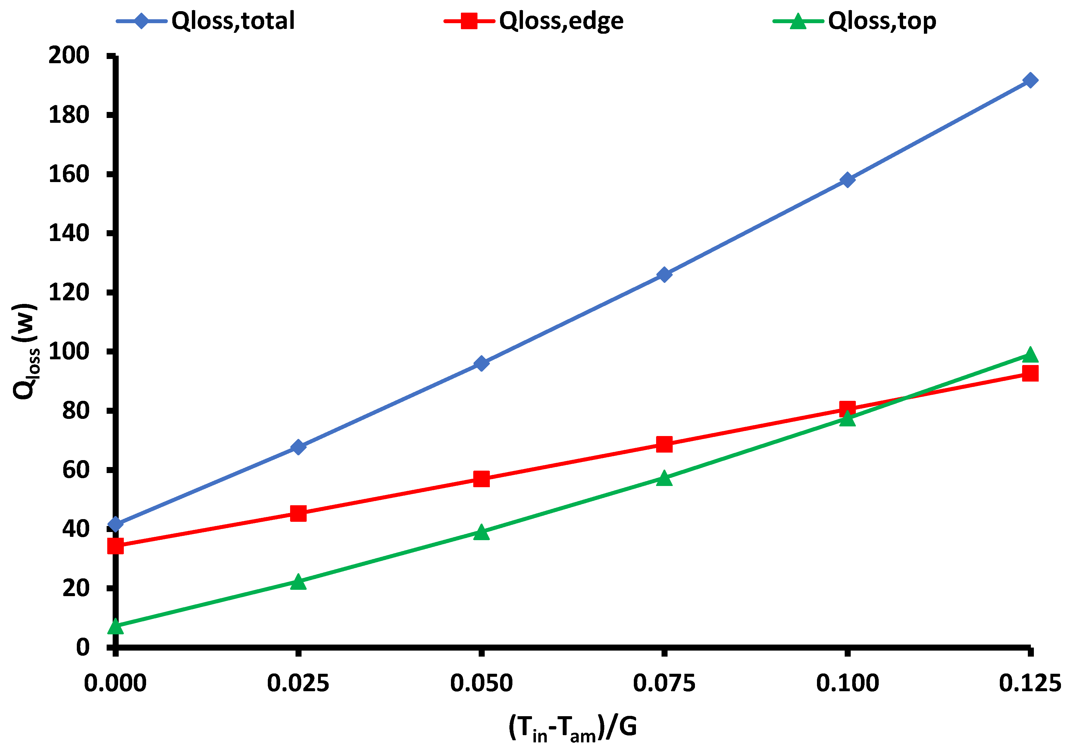
Figure 3 exhibits the thermal losses of the examined solar unit for the different cases. The total losses are separated into the top and the edge losses. The top losses are found between the cover and the environment, while the edge losses are the thermal losses from the outer cavity area to the ambient. It is clear the three curves have a linear character with the rise of the parameter [(Tin − Tam)/G], which is practically associated with the inlet temperature (Tin). The interesting result is that the slope of the top losses is greater than the edge losses. The edge losses are associated with the outer cavity area, which is an insulated area, and thus, it presents relatively restricted thermal losses. However, the edge losses are generally higher than the top losses except in higher temperatures because the edge area is significantly higher than the top area. Figure 4 depicts the top thermal loss coefficient (Ut), which is an important parameter for the characterization of a system with flat glazing. The rise in the inlet temperature leads to a rough increase in the top thermal loss coefficient, which takes values around 15 W/m2K.
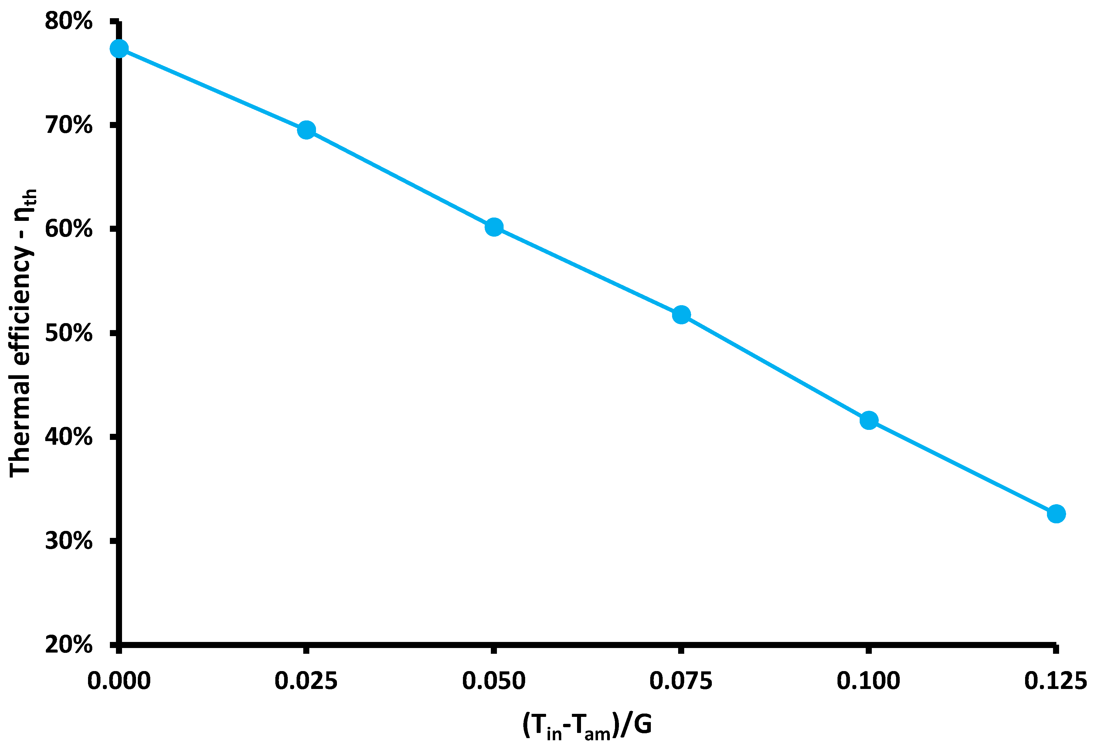
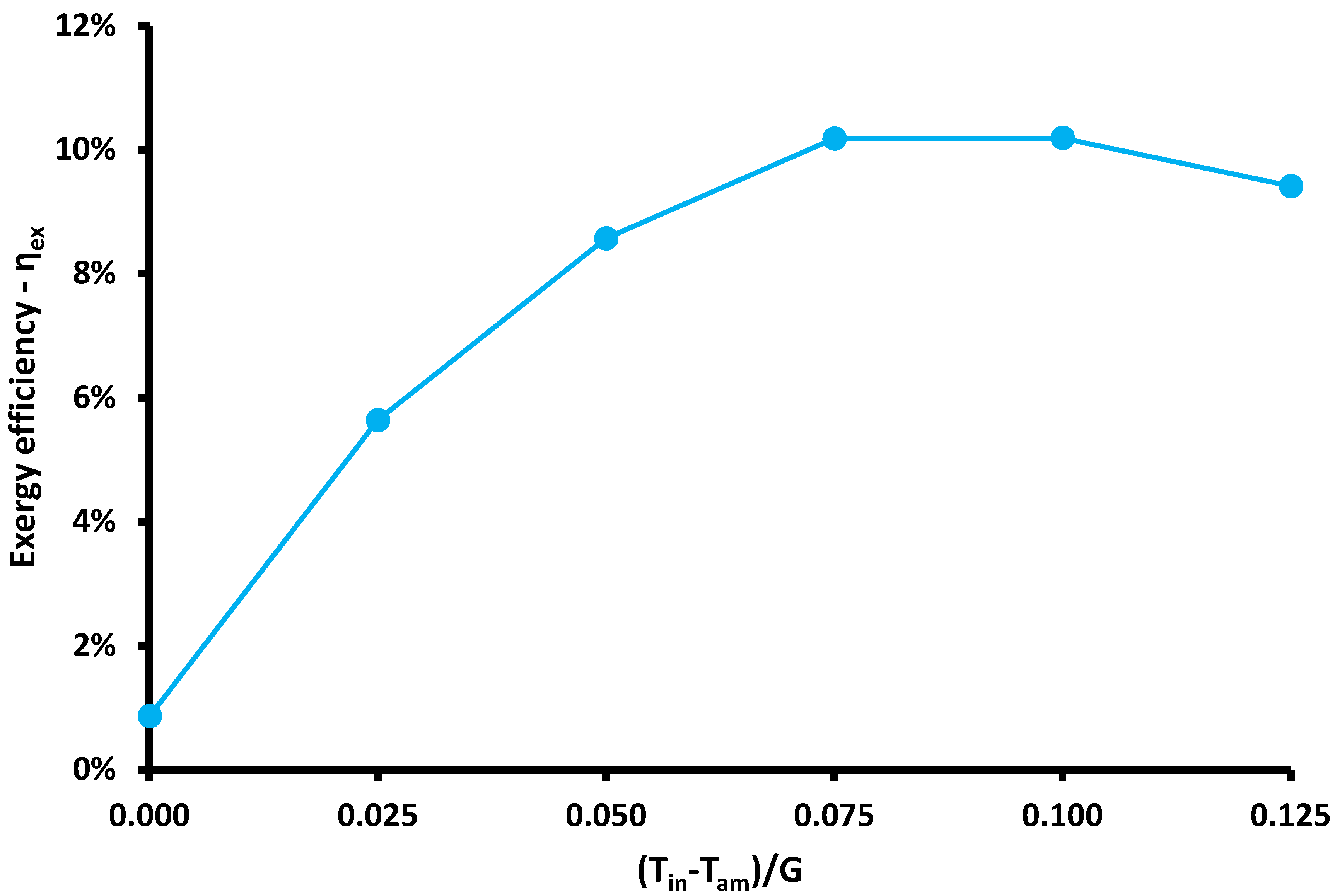
The next step regards the presentation of the performance indexes. Figure 5 displays the thermal efficiency of the solar unit and Figure 6 the exergy performance of the solar collector for the studied operating scenarios. The thermal efficiency curve has a decreasing trend with the rise of the water inlet temperature. It is a reasonable result because greater inlet temperature leads to thermal losses to be greater, which reduces the thermal efficiency. The range of thermal efficiency is found from 32.6% up to 77.4%. The thermal efficiency curve is approximated by the following linear expression with a very good fitness factor, R2 = 99.89%.
η th = 0.7808 3.6126 T in T am G
The previous equation is a very useful one which can be used for the quick and accurate evaluation of the solar collector under different operating conditions. This equation can be used in cases where the solar collector is coupled with other energy devices, and thus, it is a powerful tool for investigating the overall system performance.
The exergetic efficiency of the present solar system is maximized at 10.19% for an inlet temperature of 90 °C. This result is very interesting because it shows the present collector must be used in applications that need temperature levels around 90 °C, such as solar cooling and desalination. Hence, this system is an ideal choice for these applications. Practically, the exergy efficiency presents a maximum point because in low temperatures there is no exergy potential, while in higher temperatures there are significant thermal losses that restrict the exergy output.
At this point, it would be very interesting to discuss the possible use of the examined system in a solar cooling application. Figure 6 indicates the optimum operation close to 90 °C, which is an ideal choice for using the present system in a solar cooling configuration with an absorption chiller. The thermal efficiency of the collector for an inlet temperature of 90 °C is 41.57%, and the coefficient of performance of solar cooling at this temperature is about 0.75 by assuming a slightly lower generator temperature [33]. Thus, the overall system coefficient of performance is the product of the aforementioned indexes, and it is estimated at 0.312. For a case study of a building with 10 kW cooling needs, the solar input energy is estimated at 32.1 kW. Assuming the solar irradiation of 800 W/m2, the needed solar field area is about 40 m2, which is a reasonably available area for a building’s roof. For covering this collecting area, about 133 modules of the present solar collector must be installed. A tracking mechanism is required to achieve high performance during the day. The main axis of the solar collectors could be in the south–north direction, and the track of the sun is to be performed in the east–west direction.

3.2. Peripheral Analysis on the Absorber Tube

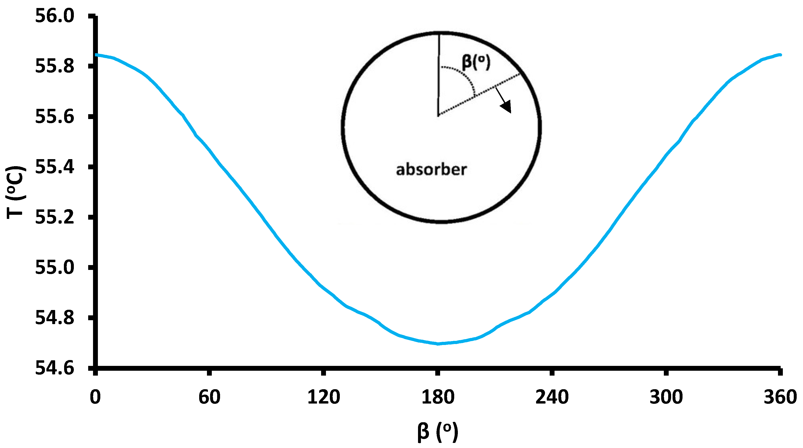
The present section includes results related to the peripheral analysis of the temperature and of heat flux in the model section of the absorber. Figure 7 illustrates the temperature distribution as a function of the peripheral angle (β) and inlet water temperature at 50 °C. The maximum temperature is found at the top point, which is 55.84 °C, while the minimum is found at the down part in the value of 55.70 °C. The variation is only 0.14 °C, which is not a high value, and indicates a relatively uniform profile. This indicates there are no “hot spots” which are associated with high thermal losses, and the danger of failure in the absorber due to the thermal stresses is restricted due to the very low peripheral temperature deviation.
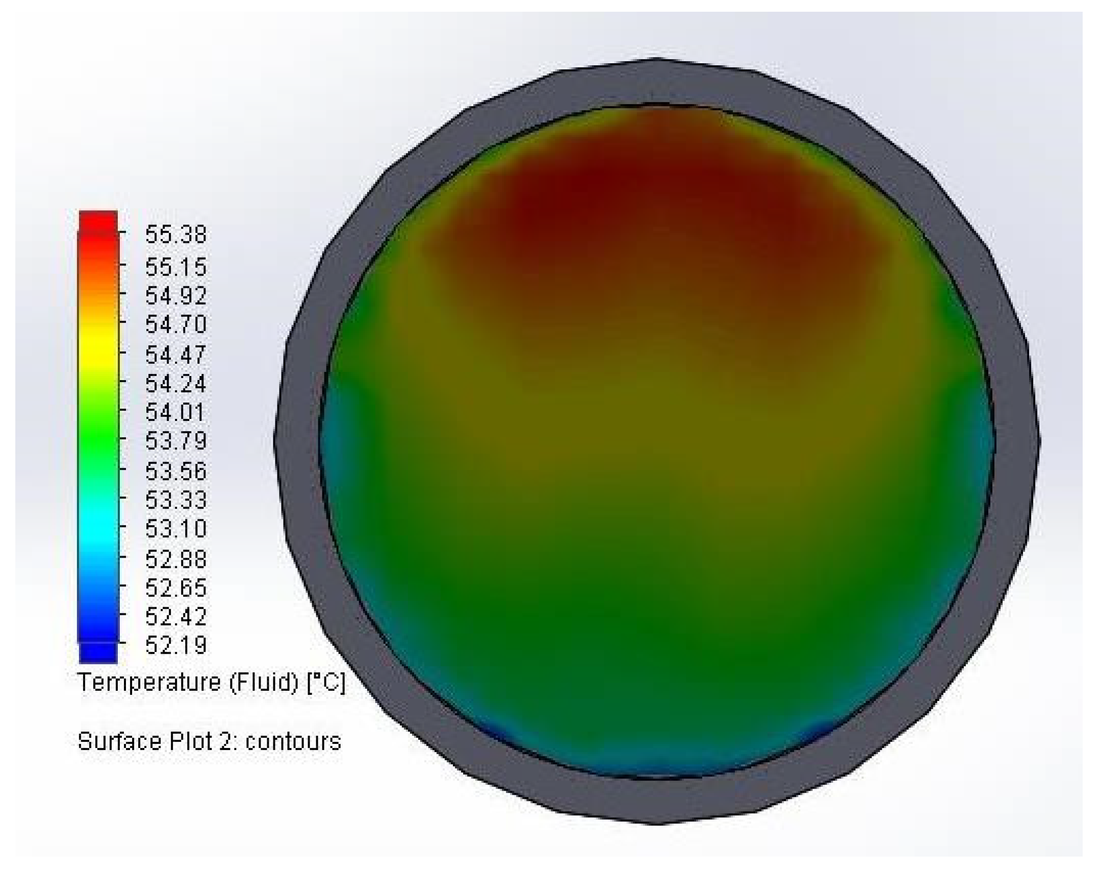
Furthermore, Figure 8 exhibits the fluid’s temperature distribution at the end of the collector. This depiction is a vertical cross-section, which indicates the water is hotter in its upper part, a result in accordance with the tube temperature distribution, which is also maximized in the upper part. The water temperature varies from 52.19 °C in the down part up to 55.38 °C in the upper part, while the mean bulk temperature is found at 54.32 °C.
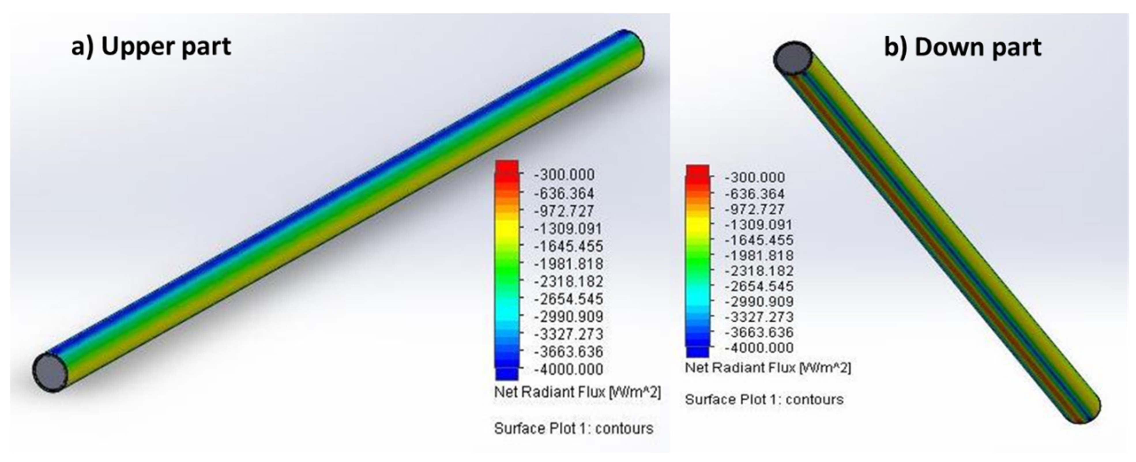
Figure 9 depicts images from the simulation model that shows the heat flux distribution over the receiver. The maximum heat flux is found at the top of the tube and the minimum at the bottom. This evidence supports the previous results, which indicate the maximum temperature at the upper part and the minimum in the down part. However, the small temperature deviation is explained by the big thermal conductivity of the absorber as a copper material.
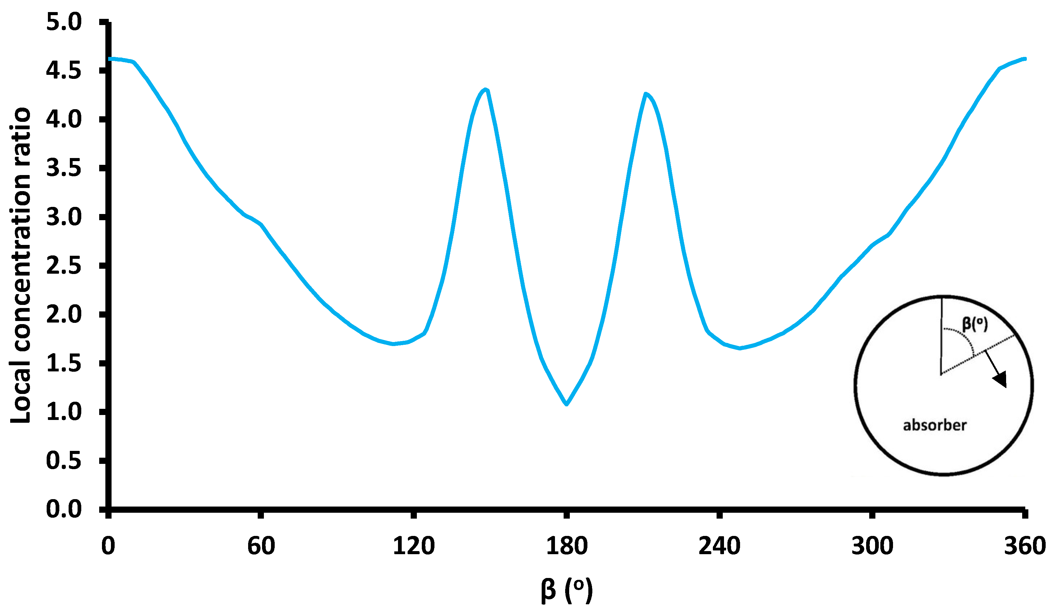
Moreover, Figure 10 depicts the local concentration ratio over the periphery of the absorber tube in the middle cross-section. The maximum local concentration ratio is found at 4.61 in the upper part, while the minimum is at 1.12 in the down part. Additionally, it is interesting that there are two symmetrical regions with a local concentration ratio of 4.29. These regions are found for the peripheral angles (β) of 150° and 210°. The mean concentration ratio is around 2.81, and there are valuable deviations between the maximum and the mean value as well as between the mean and the minimum values. However, the deviation in the temperature level is not high, which indicates the deviation of the local concentration ratio does not create efficiency issues.
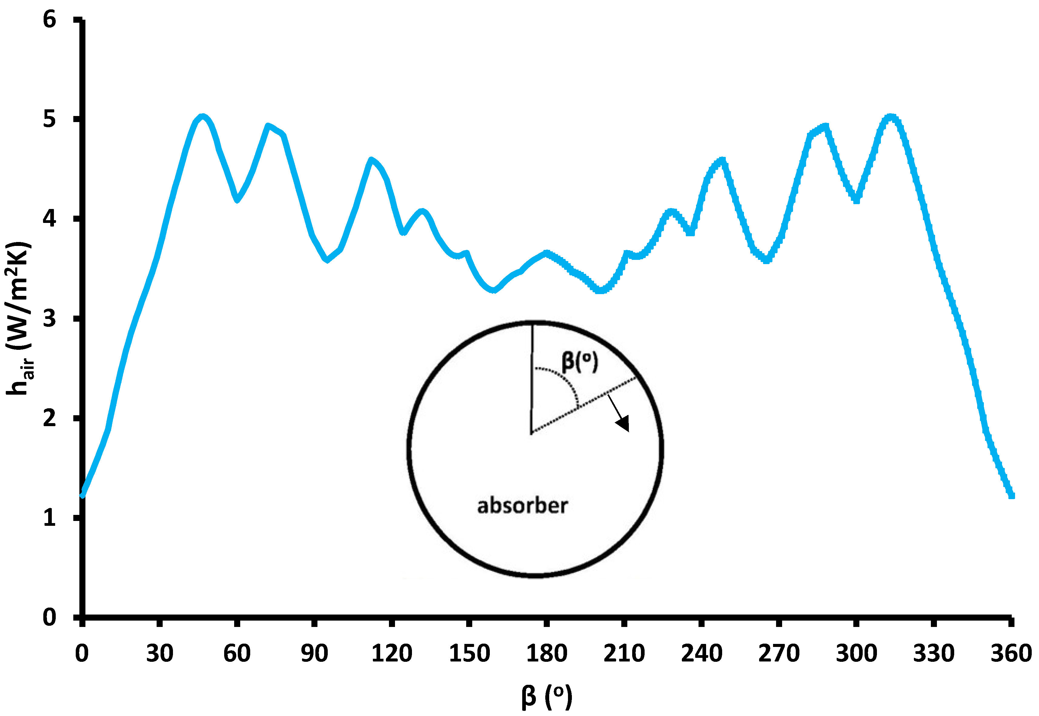
The last part of this subsection includes results for the inside heat convection coefficient between the absorber tube and inside air. This analysis is very important for the present design because the internal convection in the absorber tube is the drawback of this design compared to the evacuated tube design. Figure 11 depicts these results in the periphery of the tube in the center of the collector. The minimum value of this coefficient is found at the top point of the collector, and in this location, the heat convection coefficient is around 1.22 W/m2K, while the maximum is found at 5 W/m2K for peripheral angles at 45° and 315°, respectively. At the bottom part of the collector, the value of the heat convection coefficient was found at 3.62 W/m2K. The mean heat convection value was calculated at around 3.8 W/m2K, which is a reasonable value for a cavity. Practically, the results indicate the internal heat convection coefficient is relatively low; thus, the convection thermal losses are not so high. This result supports that the suggested collector is an efficient one, and the internal convection losses, which do not exist in the evacuated tube design, cannot reduce its performance significantly.

3.3. Temperature Distribution Profiles

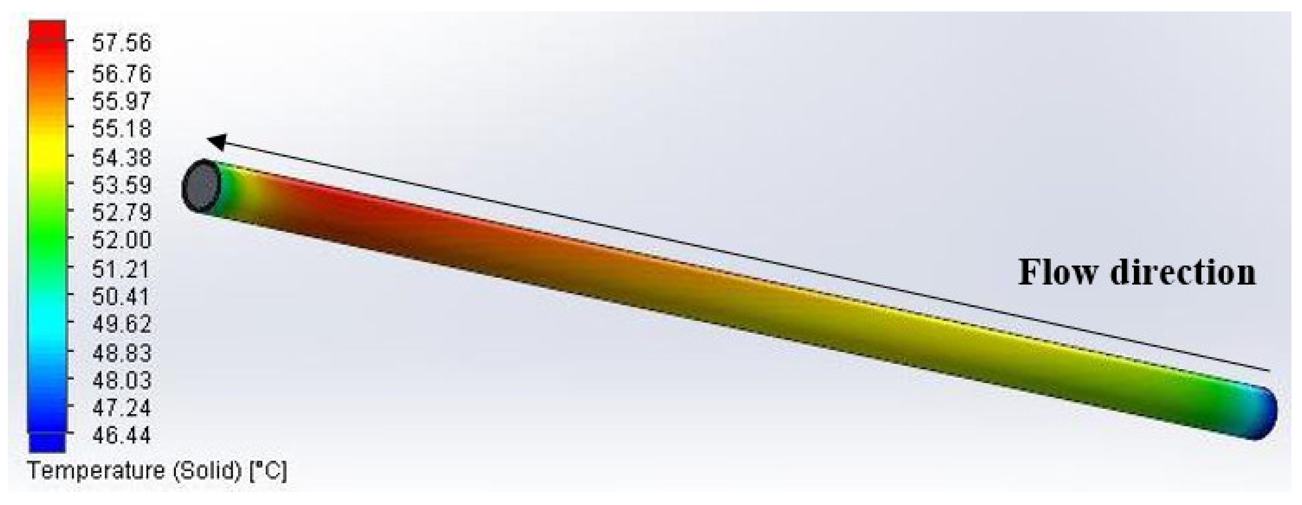
The last part of the results section includes images from the simulation analysis that lead to a deeper explanation of the behavior of the examined solar unit. Figure 12 depicts the temperature distribution over the receiver for inlet temperature at 50 °C. The absorber tube is heated from the beginning up to the end, following the fluid heating. However, at the end of the collector, there is a small cooling due to the existence of the edge boundary, which acts as a thermal bridge of the collector and reduces the absorber temperature at this point.
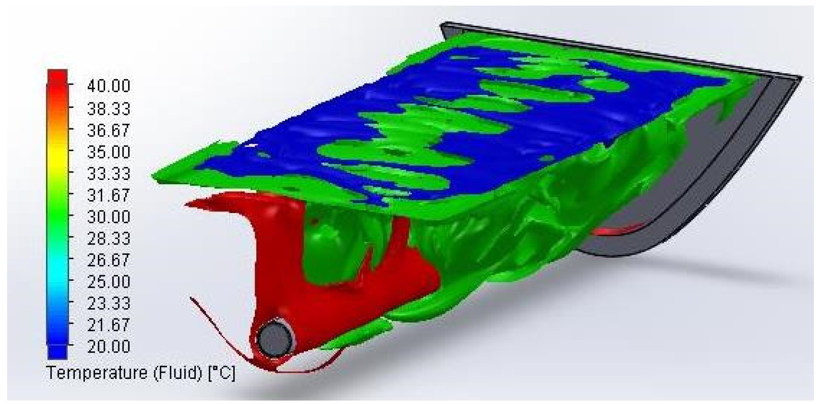
Figure 13 presents the air temperature distribution in the system in a vertical cross-section along the receiver. The air is hot close to the tube and colder close to the glass. Additionally, Figure 14 depicts air temperature iso-surfaces of 20 °C, 30 °C, and 40 °C. The majority of the enclosure has temperature levels around 30 °C, which is a reasonable result. In the present simulation, the ambient is selected at 10 °C and the inlet fluid at 50 °C; hence, the air has a mean temperature close to 30 °C, which is the mean value of the aforementioned values. This analysis indicates the results are reasonable and acceptable.
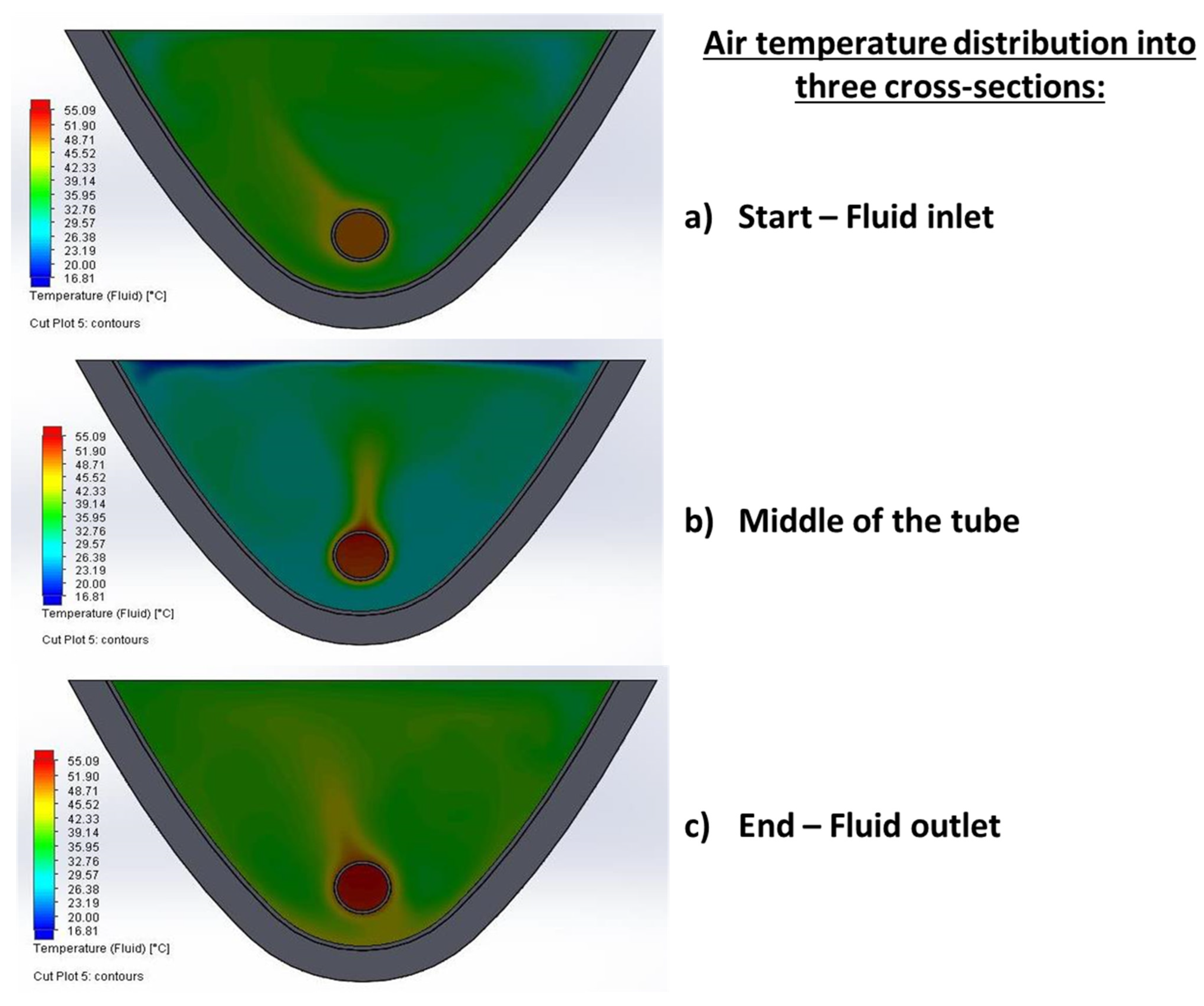
Moreover, Figure 15 shows the air temperature distribution into three cross-sections in the beginning, in the middle, and at the end of the collector. The air is hotter close to the sides compared to the center of the collector. This fact can be explained by the more intense air movement in the center of the collector, while the air cannot move with high velocities close to the sides.
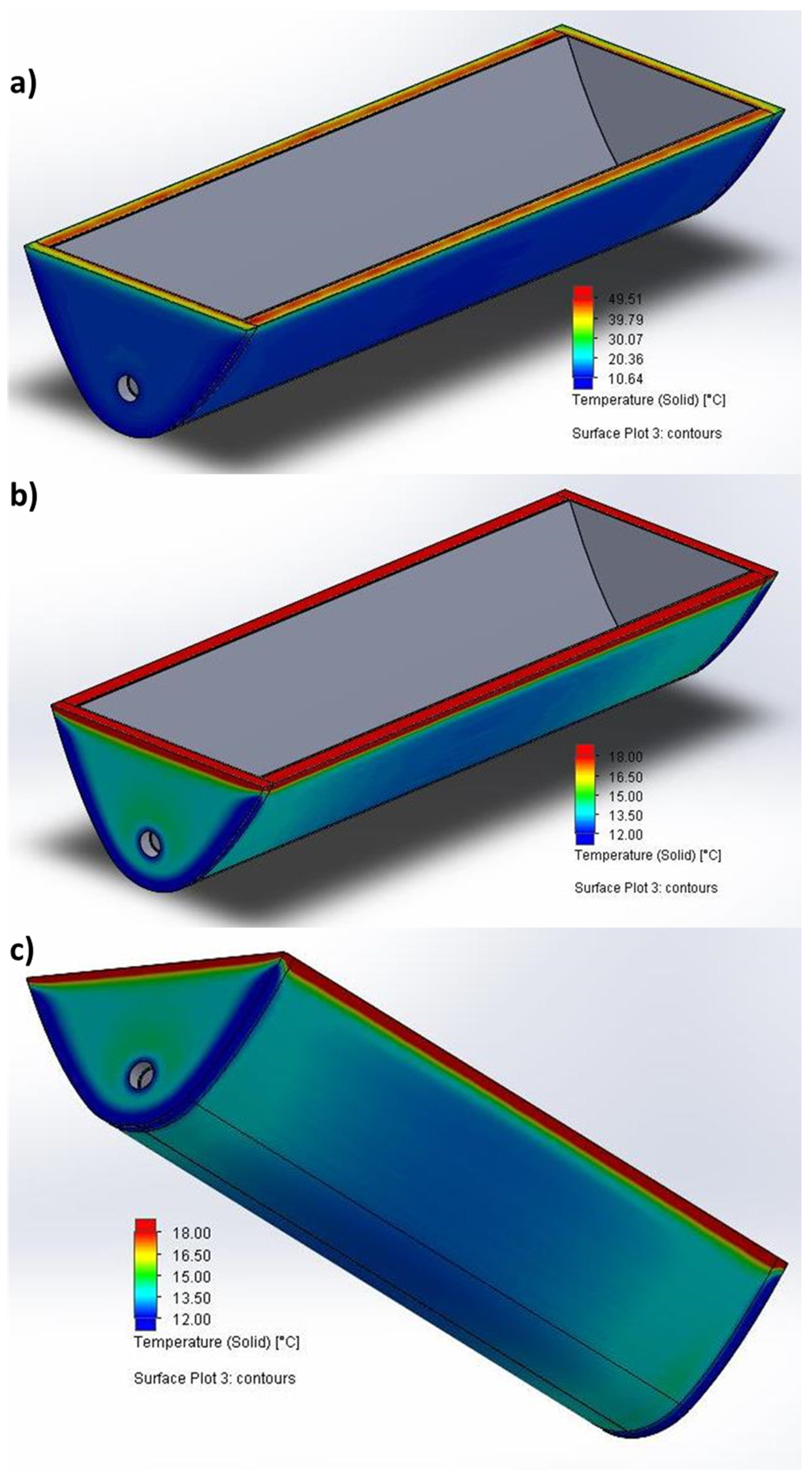
Figure 16 gives the temperature distribution in the outer area of the collector. More specifically, Figure 16a emphasizes the upper part of the collector, which reaches up to 49.51 °C due to the direct absorption of solar irradiation. Figure 16b,c emphasizes the down part of the collector, and the minimum found temperatures were close to 12 °C. The different color range among the subfigures was selected for giving the temperature distribution in detail for both the upper and lower parts of the solar unit. The locations with low temperatures close to the ambient levels indicate high thermal losses in these areas. In addition, the existence of the insulation justifies the high difference between the indoor space and the outer surface. Furthermore, the corners of the collector are the coldest areas because, in these locations, there are geometrical thermal bridges. A solution for facing this issue is the addition of extra insulation in these areas, which can be examined in future studies. The reduction of the thermal bridges can keep the indoor air at a relatively higher temperature, thus reducing the heat losses of the receiver.

4. Conclusions

Solar concentrating systems of a low concentration ratio present high interest due to the possibility of heat production for numerous applications, such as solar cooling and desalination. The present work presents a low-cost and efficient system with relatively low complexity that is based on the use of a CPC with flat glazing, which presents an acceptable efficiency. The present work is a CFD study for different operating conditions with pressurized water. The most valuable conclusions are the following:
-
The cover and receiver temperatures as well as the thermal losses have linear increasing rates with the rise of the pressurized water’s temperature at the inlet.
-
The mean heat convection value was calculated close to 3.8 W/m2K, which is a reasonable value for a closed cavity.
-
The CPC collector with flat glazing is an efficient design that presents thermal efficiency in the range of 32.6% up to 77.4% when the pressurized water temperature operates in the range of 110 °C down to 10 °C.
-
The exergy efficiency of the unit presents maximum performance for an inlet temperature of 90 °C at 10.19%. This result shows the solar unit is suitable for applications, such as solar cooling and desalination.
-
There is a need to add extra insulation in the corners of the external surface to properly face the geometrical thermal bridges at the angles, which improves the overall collector performance.

Author Contributions

Conceptualization, E.B.; Methodology, E.B.; Software, E.B. and D.N.K.; Investigation, E.B. and D.N.K.; Writing—original draft, E.B., D.N.K. and C.T.; Supervision, C.T. All authors have read and agreed to the published version of the manuscript.

Funding

D.N. Korres would like to thank Bodossaki Foundation for its financial support.

Institutional Review Board Statement

Not applicable.

Informed Consent Statement

Not applicable.

Data Availability Statement

Available after request.

Acknowledgments

D.N. Korres would like to thank Bodossaki Foundation for its financial support.

Conflicts of Interest

The authors declare no conflict of interest.

Nomenclature

AaArea of the cover, m2
cpSpecific heat capacity, J/kgK
DriInner diameter of the receiver tube, m
DroOuter diameter of the receiver tube, m
GSolar irradiation, W/m2
hairHeat convection between the absorber and inside air, W/m2K
hcaConvective coefficient between cover and ambient, W/m2K
LCollector length, m
mMass flow rate, kg/s
TamAmbient temperature, °C
TcCover temperature, °C
TinInlet temperature, °C
ToutOutlet temperature, °C
TrAbsorber temperature, °C
TsunSun temperature, K
QabsAbsorbed energy rate, W
QlossThermal losses rate, W
QuUseful energy rate, W
UtTop thermal loss coefficient, W/m2K
WCollector width, m
Greek Symbols
βAbsorber angle, °
θSolar angle at the cover surface, °
ηexExergy efficiency
ηthThermal efficiency
ηoptOptical efficiency
Subscripts and Superscripts
loss, edgeLosses from the edge of the collector
loss, totalLosses of the total collector
loss, topLosses of the top part of the collector
Abbreviations
CPCCompound parabolic concentrator

References

  1. Tian, M.; Su, Y.; Zheng, H.; Pei, G.; Li, G.; Riffat, S. A review on the recent research progress in the compound parabolic concentrator (CPC) for solar energy applications. Renew. Sustain. Energy Rev. 2018, 82, 1272–1296. [Google Scholar] [CrossRef] [Green Version]
  2. Yuan, G.; Fan, J.; Kong, W.; Furbo, S.; Perers, B.; Sallaberry, F. Experimental and computational fluid dynamics investigations of tracking CPC solar collectors. Sol. Energy 2020, 199, 26–38. [Google Scholar] [CrossRef]
  3. Masood, F.; Nor, N.B.M.; Nallagownden, P.; Elamvazuthi, I.; Saidur, R.; Alam, M.A.; Akhter, J.; Yusuf, M.; Mehmood, M.; Ali, M. A Review of Recent Developments and Applications of Compound Parabolic Concentrator-Based Hybrid Solar Photovoltaic/Thermal Collectors. Sustainability 2022, 14, 5529. [Google Scholar] [CrossRef]
  4. Winston, R. Principles of solar concentrators of a novel design. Sol. Energy 1974, 16, 89–95. [Google Scholar] [CrossRef]
  5. Xu, Z.; Wang, R. Comparison of CPC driven solar absorption cooling systems with single, double and variable effect absorption chillers. Sol. Energy 2017, 158, 511–519. [Google Scholar] [CrossRef]
  6. Sharma, G.K.; Kumar, N.; Singh, D.B.; Mallick, A. Exergoeconoic analysis of single slope solar desalination unit coupled with PVT-CPCs by incorporating the effect of dissimilarity of the rate of flowing fluid mass. Mater. Today Proc. 2020, 28, 2364–2368. [Google Scholar] [CrossRef]
  7. Carlini, M.; Rotondo, M.; Marcantonio, V.; Pierini, D.; Mennuni, A. Modeling and simulation of a cooled CPC-ORC coupled system: Performance analysis. Energy Rep. 2022, 8, 908–923. [Google Scholar] [CrossRef]
  8. Kurhe, N.; Pathak, A.; Deshpande, K.; Jadkar, S. Compound parabolic solar collector—Performance evaluation as per standard test method and actual field conditions for industrial process heat application in Indian context. Energy Sustain. Dev. 2020, 57, 98–108. [Google Scholar] [CrossRef]
  9. Said, Z.; Ghodbane, M.; Boumeddane, B.; Tiwari, A.K.; Sundar, L.S.; Li, C.; Aslfattahi, N.; Bellos, E. Energy, exergy, economic and environmental (4E) analysis of a parabolic trough solar collector using MXene based silicone oil nanofluids. Sol. Energy Mater. Sol. Cells 2022, 239, 111633. [Google Scholar] [CrossRef]
  10. Bellos, E. Progress in the design and the applications of linear Fresnel reflectors—A critical review. Therm. Sci. Eng. Prog. 2019, 10, 112–137. [Google Scholar] [CrossRef]
  11. Garg, A.; Ray, B.; Jain, S. Development of Nusselt number correlation for solar CPC with a tubular receiver. Therm. Sci. Eng. Prog. 2023, 37, 101553. [Google Scholar] [CrossRef]
  12. Qiu, Y.; Li, M.-J.; Wang, K.; Liu, Z.-B.; Xue, X.-D. Aiming strategy optimization for uniform flux distribution in the receiver of a linear Fresnel solar reflector using a multi-objective genetic algorithm. Appl. Energy 2017, 205, 1394–1407. [Google Scholar] [CrossRef] [Green Version]
  13. Subramaniyan, C.; Subramani, J.; Kalidasan, B.; Anbuselvan, N.; Yuvaraj, T.; Prabaharan, N.; Senjyu, T. Investigation on the Optical Design and Performance of a Single-Axis-Tracking Solar Parabolic trough Collector with a Secondary Reflector. Sustainability 2021, 13, 9918. [Google Scholar] [CrossRef]
  14. Devanarayanan, K.; Murugavel, K.K. Integrated collector storage solar water heater with compound parabolic concentrator—Development and progress. Renew. Sustain. Energy Rev. 2014, 39, 51–64. [Google Scholar] [CrossRef]
  15. Ma, G.; Yin, Z.; Liu, X.; Qi, J.; Dai, Y. Developments of CPC solar evacuated glass tube collector with a novel selective coating. Sol. Energy 2021, 220, 1120–1129. [Google Scholar] [CrossRef]
  16. Liu, Z.; Tao, G.; Lu, L.; Wang, Q. A novel all-glass evacuated tubular solar steam generator with simplified CPC. Energy Convers. Manag. 2014, 86, 175–185. [Google Scholar] [CrossRef]
  17. Korres, D.; Tzivanidis, C. A new mini-CPC with a U-type evacuated tube under thermal and optical investigation. Renew. Energy 2018, 128, 529–540. [Google Scholar] [CrossRef]
  18. Bellos, E.; Korres, D.; Tzivanidis, C.; Antonopoulos, K. Design, simulation and optimization of a compound parabolic collector. Sustain. Energy Technol. Assess. 2016, 16, 53–63. [Google Scholar] [CrossRef]
  19. Korres, D.; Bellos, E.; Tzivanidis, C. Investigation of a nanofluid-based compound parabolic trough solar collector under laminar flow conditions. Appl. Therm. Eng. 2019, 149, 366–376. [Google Scholar] [CrossRef]
  20. Souliotis, M.; Tripanagnostopoulos, Y. Experimental study of CPC type ICS solar systems. Sol. Energy 2004, 76, 389–408. [Google Scholar] [CrossRef]
  21. Tripanagnostopoulos, Y.; Souliotis, M. ICS solar systems with two water tanks. Renew. Energy 2006, 31, 1698–1717. [Google Scholar] [CrossRef]
  22. Tripanagnostopoulos, Y.; Souliotis, M. ICS solar systems with horizontal (E–W) and vertical (N–S) cylindrical water storage tank. Renew. Energy 2004, 29, 73–96. [Google Scholar] [CrossRef]
  23. Tripanagnostopoulos, Y.; Souliotis, M. Integrated collector storage solar systems with asymmetric CPC reflectors. Renew. Energy 2004, 29, 223–248. [Google Scholar] [CrossRef]
  24. Korres, D.N.; Bellos, E.; Tzivanidis, C. Integration of a Linear Cavity Receiver in an Asymmetric Compound Parabolic Collector. Energies 2022, 15, 8635. [Google Scholar] [CrossRef]
  25. Zhang, X.; Jiang, S.; Lin, Z.; Gui, Q.; Chen, F. Model construction and performance analysis for asymmetric compound parabolic concentrator with circular absorber. Energy 2023, 267, 126597. [Google Scholar] [CrossRef]
  26. Redpath, D.; Paneri, A.; Singh, H.; Ghitas, A.; Sabry, M. Design of a Building-Scale Space Solar Cooling System Using TRNSYS. Sustainability 2022, 14, 11549. [Google Scholar] [CrossRef]
  27. Garcia, J.M.; Rosa, A. Theoretical Study of an Intermittent Water-Ammonia Absorption Solar System for Small Power Ice Production. Sustainability 2019, 11, 3346. [Google Scholar] [CrossRef] [Green Version]
  28. Masood, F.; Nallagownden, P.; Elamvazuthi, I.; Akhter, J.; Alam, M. A New Approach for Design Optimization and Parametric Analysis of Symmetric Compound Parabolic Concentrator for Photovoltaic Applications. Sustainability 2021, 13, 4606. [Google Scholar] [CrossRef]
  29. SOLIDWORKS Flow Simulation. SOLIDWORKS 2017. Available online: https://www.solidworks.com/product/solidworks-flow-simulation (accessed on 24 January 2023).
  30. Petela, R. Exergy of undiluted thermal radiation. Sol. Energy 2003, 74, 469–488. [Google Scholar] [CrossRef]
  31. Vahidinia, F.; Khorasanizadeh, H.; Aghaei, A. Energy, exergy, economic and environmental evaluations of a finned absorber tube parabolic trough collector utilizing hybrid and mono nanofluids and comparison. Renew. Energy 2023, 205, 185–199. [Google Scholar] [CrossRef]
  32. Qiu, Y.; Li, M.-J.; He, Y.-L.; Tao, W.-Q. Thermal performance analysis of a parabolic trough solar collector using supercritical CO2 as heat transfer fluid under non-uniform solar flux. Appl. Therm. Eng. 2017, 115, 1255–1265. [Google Scholar] [CrossRef]
  33. Zhang, F.; Yin, Y.; Cao, B.; Wang, Y. Performance analysis of a novel dual-evaporation-temperature combined-effect absorption chiller for temperature and humidity independent control air-conditioning. Energy Convers. Manag. 2022, 273, 116417. [Google Scholar] [CrossRef]
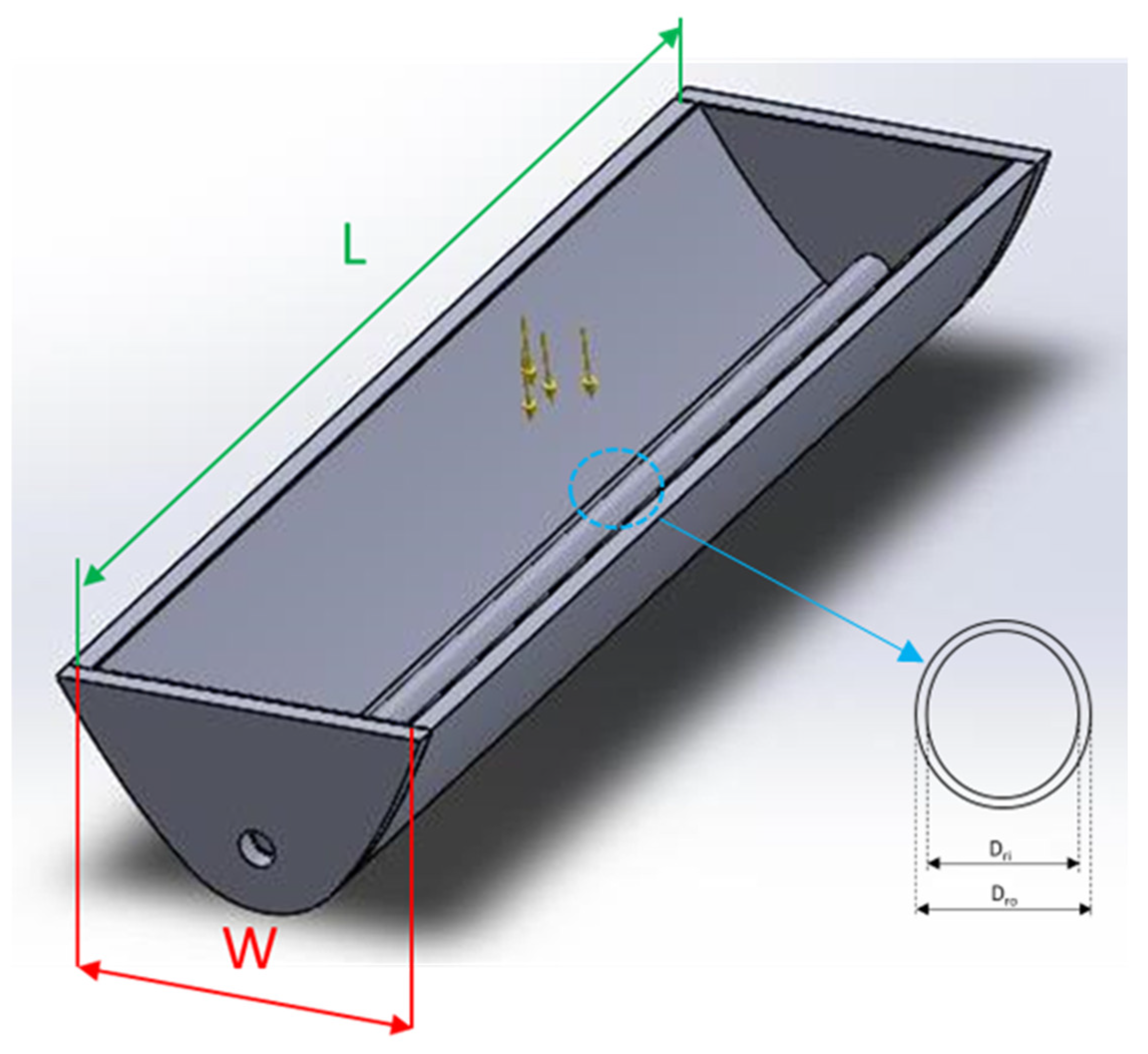
Figure 1. The designed CPC with flat glazing.
Sustainability 15 04347 g001
Figure 2. Mean absorber (Tr) and mean cover (Tc) temperature distribution for the different studied cases.
Sustainability 15 04347 g002
Figure 3. Thermal loss variation (total, top, edge) for the different studied cases.
Sustainability 15 04347 g003
Figure 4. Top thermal loss coefficient for the different studied cases.
Sustainability 15 04347 g004
Figure 5. Thermal efficiency for the different studied cases.
Sustainability 15 04347 g005
Figure 6. Exergy efficiency for the different studied cases.
Sustainability 15 04347 g006
Figure 7. Peripheral temperature distribution on the receiver tube for inlet temperature at 50 °C.
Sustainability 15 04347 g007
Figure 8. Fluid outlet temperature at the outlet’s cross-section for inlet temperature at 50 °C.
Sustainability 15 04347 g008
Figure 9. Solar irradiation distribution in the receiver tube. The blue color indicates the higher values and the red color the lower values, while the negative sign has only a logistic meaning.
Sustainability 15 04347 g009
Figure 10. Local concentration ratio on the absorber tube peripheral line.
Sustainability 15 04347 g010
Figure 11. Peripheral distribution of the heat convection coefficient between the receiver tube and inside air in the collector (a case study for inlet temperature at 50 °C).
Sustainability 15 04347 g011
Figure 12. Temperature distribution over the absorber tube for inlet temperature at 50 °C.
Sustainability 15 04347 g012
Figure 13. Air temperature distribution inside the collector on a vertical cross-section in the middle of the collector for inlet temperature at 50 °C.
Sustainability 15 04347 g013
Figure 14. Temperature iso-surfaces for the air temperature inside the collector for inlet temperature at 50 °C.
Sustainability 15 04347 g014
Figure 15. Air temperature distribution into three vertical cross-sections.
Sustainability 15 04347 g015
Figure 16. Temperature distribution over the outer collector surface for inlet temperature at 50 °C. (a) Top view with a temperature range of 10.64–49.51 °C, (b) Top view with a temperature range of 12–18 °C, (c) Down view with a temperature range of 12–18 °C.
Sustainability 15 04347 g016
Table 1. Basic design parameters of the solar unit.
ParametersValues
Concentration ratio2.81
Absorber emissivity0.1
Glass cover emissivity0.88
Optical efficiency for zero solar angle80%
Useful collector’s width0.3 m
Useful collector’s length1 m
Focal distance of the parabola0.05 m
Absorber inside diameter0.030 m
Absorber outside diameter0.034 m
Cover thickness4 mm
External insulation thickness0.02 m
Thermal conductivity of the insulation0.035 W/mK
Table 2. Basic simulation inputs.
ParameterSymbolValues
Mass flow ratem0.01 kg/s
Inlet temperatureTin10, 30, 50, 70, 90, 110 °C
Ambient temperatureTam10 °C
Heat convection coefficient with the ambienthca10 W/m2K
Solar irradiationG800 W/m2
Solar angleθ
Disclaimer/Publisher’s Note: The statements, opinions and data contained in all publications are solely those of the individual author(s) and contributor(s) and not of MDPI and/or the editor(s). MDPI and/or the editor(s) disclaim responsibility for any injury to people or property resulting from any ideas, methods, instructions or products referred to in the content.