Article

Thermoelectric Generator Using Low-Cost Thermoelectric Modules for Low-Temperature Waste Heat Recovery

by
Manuela Castañeda
1,
Andrés A. Amell
2,
Mauricio A. Correa
3,
Claudio E. Aguilar
4 and
Henry A. Colorado
1,*
1
CCComposites Laboratory, Universidad de Antioquia UdeA, Calle 70 N°. 52-21, Medellín 050010, Colombia
2
Grupo de Ciencia y Tecnología del Gas y Uso Racional de la Energía, Facultad de Ingeniería, Universidad de Antioquia UdeA, Calle 70 N°. 52-21, Medellín 050010, Colombia
3
Grupo de Investigación y Laboratorio de Monitoreo Ambiental -GLIMA-, Universidad de Antioquia UdeA, Calle 70 N°. 52-21, Medellín 050010, Colombia
4
Department of Metallurgical Engineering and Materials, Universidad Técnica Federico Santa María, Valparaíso 2340000, Chile
*
Author to whom correspondence should be addressed.
Sustainability 2023, 15(4), 3681; https://doi.org/10.3390/su15043681
Submission received: 22 October 2022 / Revised: 29 November 2022 / Accepted: 1 December 2022 / Published: 16 February 2023
(This article belongs to the Special Issue Sustainable Development of Energy Conversion and Storage Devices)

Abstract

:
One of the most significant problems in industrial processes is the loss of energy according to the sort of heat. Thermoelectrics are a promising alternative to recovering this type of thermal energy, as they can convert heat into electricity, improving the industrial efficiency of the process. This article presents the characteristics of low-cost thermoelectric modules typically used for generation (SP1848-27145SA (TEG-GEN)) and refrigeration (TEC1-12706 (TEC-REF)), both utilized in this research for heat recovery. The modules were evaluated against various configurations, source distances, and distributed systems in order to determine optimal recovery conditions. The experiments were conducted both at the laboratory level and in a large-scale furnace of the traditional ceramics industry, and they revealed that even refrigeration modules are suitable for energy recovery, particularly in developing countries, whereas other generators are more expensive and difficult to obtain. These thermoelectric generators were tested for low-temperature heat recovery in regular furnaces, and the results are to be implemented elsewhere. Results show that even the thermoelectric refrigeration modules can be a solution for heat recovery in many heat sources, which would be particularly strategic for developing countries.

1. Introduction

The current COVID-19 crisis has generated essential changes in the contemporary lifestyle, leading to greater awareness of the use of available resources [1]. The environmental and social impacts caused by the various energy generation technologies used today are becoming more and more evident. Of these technologies, nearly 70% of energy is produced through non-renewable sources such as coal, oil, and nuclear energy [2]. In addition to this, the economic and population increase is directly proportional to energy expenditure worldwide, and although by 2020, the demand for energy decreased by approximately 4.5% due to the health contingency from COVID-19 [3], it is expected that with the economic reactivation and the lifting of restrictions, this percentage will decrease significantly [4]. Therefore, the search for new renewable sources is a global need [5].
From a material science point of view, there are multiple approaches to providing solutions to the energy demand, the environmental crisis, and energy waste: rechargeable batteries [6], solar cells [7], piezoelectrics [8], wind energy [9], nuclear energy [10], thermoelectrics [11], and more. Thermoelectric materials, aside from the current limitations of their generated power, show promising potential to decrease waste energy and pollution [12].
The most outstanding attribute of thermoelectric materials is that they can generate energy by taking advantage of the temperature difference between two environments, which can be used in multiple industrial processes in which energy is wasted and discarded into the environment according to the sort of heat [13,14,15,16]. In this scenario, thermoelectric materials could play a significant role in generating unpolluted energy by recovering residual energy from different industrial processes, such as the automotive [17], aerospace [18], industrial [19], and construction sectors [20], among others [21].
Thermoelectric materials are usually found in solid-state devices called thermoelectric modules, which are composed of an array of thermocouples and semiconductor materials alternating between two ceramic plates of high thermal conductivity [22]. In general, commercial thermoelectric modules are divided into two groups: thermoelectric cooling modules (TEC), [23] and thermoelectric generation modules (TEG) [18]. TEC modules are mainly designed so that when an electric current is applied, a change in temperature is generated between their faces (what is known as the Peltier effect), so the materials that constitute it must tolerate low temperatures. On the other hand, the TEG modules are designed so that, when experiencing a change in temperature between their faces, they provide a difference in electrical potential (Seebeck effect). In these modules, the materials used in their construction must tolerate higher temperatures than in the case of TEC modules, which makes this type of thermoelectric module more expensive [24]. Although the TEC and TEG modules are conceived for different purposes, the operation of these modules is governed by thermoelectric effects (Seebeck, Peltier, and Thomson effects), effects that are reversible so that the two types of modules can be used, for both generation and cooling. Therefore, the extreme temperatures to which the materials that make up the modules are subjected must be taken into consideration [25].
Thermoelectric modules exhibit certain advantages compared to conventional generation systems, such as the absence of moving parts, being compact components, presenting silent operation, and having a long, useful life. However, in turn, they exhibit clear limitations that prevent this type of power generation system from being optimal from an efficiency–cost approach. In this sense, its main limitations lie in its low thermal conversion efficiency (approximately 4% in commercial modules), its high cost due to the materials that constitute it, and the complexity of the processes required for its production [26]. Likewise, in modules for power generation applications, an effective temperature difference must be certified between the faces of the module. Therefore, incorporating a cooling mechanism into the low-temperature face of the module would allow greater efficiency, and help to achieve energy recovery [27,28].
The most common thermoelectric modules at an industrial level are those built with Bi2Te3 base material. These modules are used for low temperatures, and are readily available at lower prices in the market. As mentioned above, one of the major drawbacks of thermoelectric modules is their high cost/efficiency ratio, which makes it difficult to introduce them to the industries of many countries. Thus, the central focus of current research is to improve the efficiency of the modules through manufacturing processes, or to improve the base material so as to finally introduce the current commercial modules at the industrial level through the union of methods in a hybrid clean power generation process [12].
The present study is aimed at developing and optimizing a TEG system from three approaches: (1) the selection of thermoelectric materials with a high number of merit (greater efficiency), low cost, and easy manufacturing; the latter is due to the fact that the recent development of materials with higher efficiency, such as Half Heusler alloys [29], Skutterudite materials [30], and nanostructured materials [31], among others, exhibit improved performance. However, in most cases, their manufacturing at an industrial level is limited due to their high manufacturing complexity and high production cost; (2) the redesign of thermoelectric modules seeking to improve their performance [24]; and (3) the design of cooling devices for thermoelectric generators [31,32,33].
It is estimated that the residual heat generated in industrial processes can reach up to 50% of the primary energy inputs. These energy dissipations are usually present in the exhaust gases, waste fluids, and evaporation processes, stages wherein radiation phenomena are induced, among others [18,33]. Such circumstances make the incorporation of thermoelectric generators very attractive for the purpose of taking advantage of the residual heat present in the different industrial processes. In general, residual heat is classified into three categories according to the temperatures reached in the processes involved; according to this categorization, residual temperatures are low when they are below 100 °C; they are considered medium when the temperature varies between 100 °C and 300 °C; and, finally, when temperatures are above 300°C, they are considered high [34].
In this study, two low-cost thermoelectric modules were characterized, a refrigeration module reference (TEC1-12706 (TEC)) and a thermoelectric generation module reference (SP1848-27145SA (SP)), with the aim of manufacturing a thermoelectric generator system (TGS) for the recovery of waste heat at a low-medium temperature on an industrial level. The modules were evaluated at the laboratory level in different configurations, distances from the source, and with a finned heat dissipation system in order to establish improved energy recovery conditions. The manufactured TGS was designed for heat recovery in low-medium residual temperature processes, and was tested in an industrial drying oven of the Sumicol SAS company.
This article provides an overview of the efficiency and challenges of incorporating thermoelectric heat recovery systems, made with economic thermoelectric cells marketed in Latin America, when evaluated at the laboratory level (under controlled conditions) and at an industrial level (under uncontrollable conditions). The project is part of a local strategy to improve material circularity [35,36] and energy optimization [37,38,39] in materials and industrial processes in the country, which are issues which have been considered important for decades at the legislative and technological levels. The case study presented here is applicable elsewhere, and is a particularly inexpensive and green solution, feasible to run in developing countries where generation cells are difficult to obtain.

2. Materials and Methods

First, the structural assembly of the TGS was designed, which included two complementary components: a metal plate that might need to be in contact with the brink of the warmth source, and a finned conductor component for cooling the cold face of the modules, aiming to improve the temperature difference on the faces of the thermoelectric modules. Subsequently, the thermoelectric modules were placed between the metal conductors; see Figure 1.
Table 1 shows the technical specifications of the thermoelectric modules, SP1848-27145SA (TEG-GEN) and TEC1-12706 (TEC-REF), used to assemble the TGS provided by the manufacturer.
An assembly was implemented where the heat was supplied through electrical resistances, in which the voltage (mV) and current (mA) values were recorded by different TGS configurations. The TGS configurations were made up of arrangements of 2 and 6 interconnected thermoelectric modules. In the case of the TGS, it was made up of 2 thermoelectric modules, and serial and parallel connections were implemented. For the TGS, it was made up of 6 thermoelectric modules, and serial and mixed connections (combination between modules connected in series and in parallel, see Figure 2 were used. Likewise, two distances from the TGS to the heat source were evaluated.
Later, an in situ large-scale company furnace facility was tested using the assembly of the TGS made up of 6 modules, with the same connections used at the laboratory level, but now with a real process occurring (Figure 3). The heat source, in this case, was the surface of a drying oven of the Colombian company Sumicol SAS, the larger-scale company of traditional ceramics in Colombia. In this process, a measurement of the surface temperature of the furnace wall was made using thermographic techniques. The TGS was mounted vertically, and the respective voltage (mV) and current (mA) measurements were taken.
Figure 4 is a diagram of the assembly of the experimental platform used, consisting of the thermoelectric generator with the cells; the fin-type heat dissipation system; and the data acquisition system, which delivers the information of cold side temperature, hot side temperature, temperature delta (temperature range: 0 to 800 °C), voltage (range: 0 V to 26 V DC), and current (range: 0 to 3.2 A) and inputs it into Microsoft Excel.

3. Results and Discussion

The modules used (see Table 1) present a reasonable difference in their cost, the SP1848-27145SA module being USD 0.45 more expensive than the TEC1-12706 module. The technical sheet of the two types of modules is quite different, due to the targeted application for which each one is commercially intended. The SP1848-27145SA module is sold as a generation module capable of withstanding a maximum temperature of 100 °C between faces, and the TEC1-12706 module is sold as a cooling module and supports a temperature range of 66–75 °C between the faces. The modules evaluated are composed of bismuth telluride-based materials, both n-type and p-type.
The evaluation of different TGSs was carried out under the experiment design shown in Table 2, which specifies the parameters for both laboratory and industrial-level tests in the drying oven.

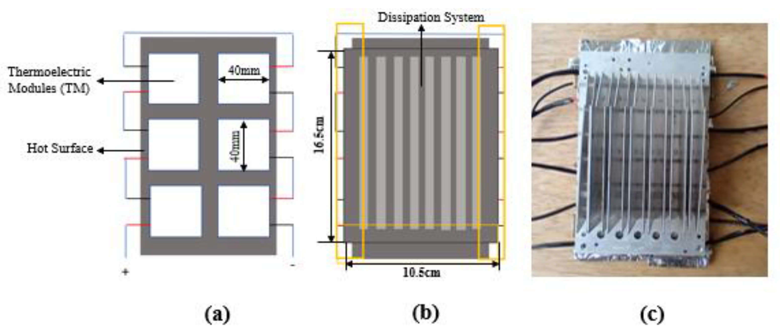
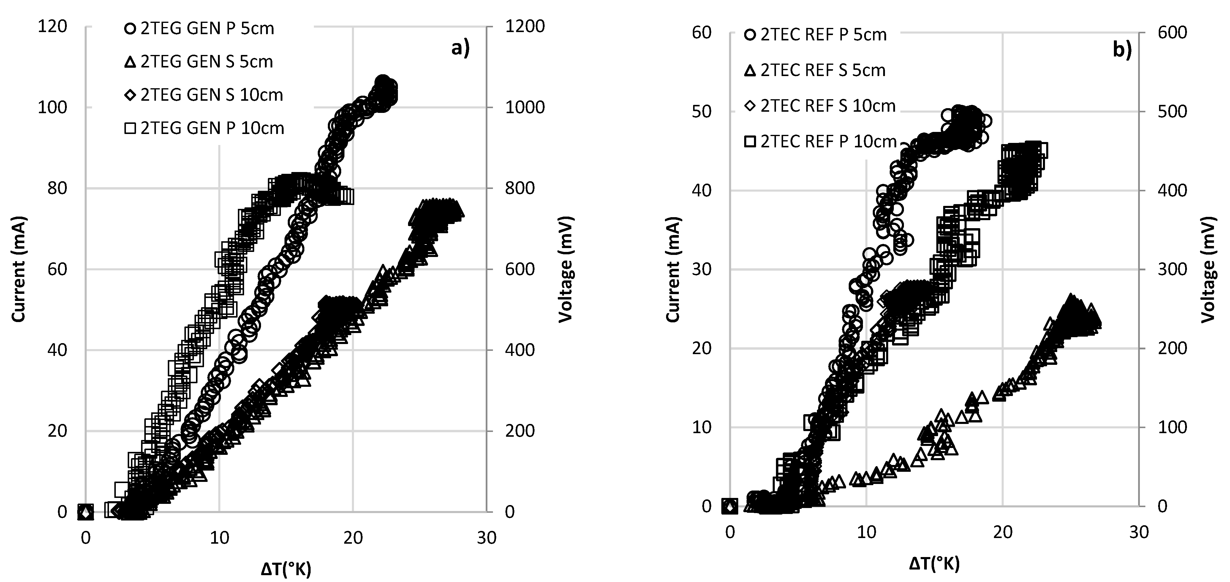
3.1. Characterization of Commercial Thermoelectric Cells and Construction of the TGS

Figure 5 shows the results for two TGSs of each reference. The modules used were SP1848-2714SA (TEG GEN) and TEC-12706 (TEC REF) in both series and parallel connections at different distances (5 and 10 cm from the heat source). The average temperature of the source was 530 ± 3 °C. For the two cell references, a higher power generation could be observed when the connection between the modules was in parallel. In the case of the reference SP1848-2714SA, the configuration that exhibited the better voltage and current recovery was obtained through parallel connections, with a distance of 5 cm from the source, and reached a temperature difference of 22.25 °C (Tc = 70.75 °C and Th = 93 °C), a voltage of 1068 mV, and a current of 106.1 mA. In this configuration, despite presenting the best performance when reaching maximum difference temperature for each case, the current and voltage began to decrease.
Figure 5 also shows some fluctuations in the data, which have been related to the time interval for collecting the information from the data acquisition system, which is an interval of 2400 ms between samples, and to the rapid increase in temperature delta experienced by the faces of the thermoelectric modules. It was also observed that when the modules reached their maximum generation point, the temperatures of the two faces began to equalize, which resulted in a concentration of data in the final part of the graphs.
The reference of modules TEC-12706 presented a better performance in the configuration parallel to 5 cm of distance from the source at a different temperature of 17.5 °C (Tc = 78.75 °C and Th = 96.25 °C), and obtained a voltage of 506.4 mV and a current of 49.8 mA. It can be seen in Table 3 that a large difference in temperature between the faces of the cells is important, since this does not guarantee a good performance in the generation of power. This can be seen in the tests 2TEC REF P 5cm and 2TEC REF S 5cm, in which the difference in temperature is not directly linked to the voltage, current, or electrical power generated by the cells.
In the TGS GEN P 5 cm and 2TEC REF P 10 cm, it was observed that the maximum generation for each of the cells was given for a different temperature, 22.25 °C. This differential temperature is given in very similar values of the cold and hot faces of the cells in the two tests. However, the voltage generation and electrical power reflect the generation capacity of each of the cells, and it can be observed that the SP1848-2714SA cells come to generate more than double the energy generated by the TEC-12706 cell under the same conditions. This is due to the nature of the modules which, in the case of the latter, are manufactured for thermoelectric cooling, while sp1848-2714SA cells are generating cells, and support a much higher temperature range.
Figure 6 shows the voltage and current production of thermoelectric cells for laboratory-level tests on six thermoelectric modules, SP1848-2714SA and TEC-12706, in mixed and serial connection. The results obtained for the TEC1-10706 modules in the different connections, 6TEC-REF-S-5cm and 6TEC-REF-M-5cm, do not show a significant difference in power generation. On the other hand, among the connections in which the SP1848-27145SA modules were evaluated, a significant difference was observed with respect to the type of connection. For the 6TEG-GEN-M-5cm test, in which two groups of three modules were connected in series and then connected in parallel, the difference temperature that was reached was 35 °C, and a power generation of 40 mA and 400 mV was achieved. When compared to the 6TEG-GEN-S-5cm test, in which the modules were connected in series, the power generation was higher than 47 mA and 450 mV, but the maximum difference temperature before the cells began to decrease was 17 °C.
Table 4 shows the efficiencies obtained in each 6-cell connection, finding that the highest efficiency is obtained in the 6TEG-GEN-M-5cm connection at a temperature delta of 17.3 °C.

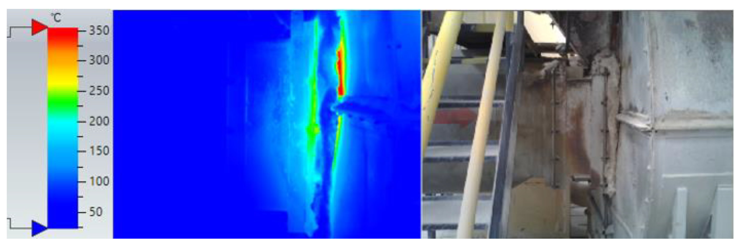
3.2. Industrial-Level Tests in a Drying Oven of the Sumicol S.A.S Company

When characterizing the heat source, the drying oven of the company Sumicol S.A.S (see Figure 7) was found to have an approximate surface temperature of 163 ± 54 °C. Therefore, the assembly was carried out with the configurations of Table 2. The results of the differential temperature between the faces of the cell, electrical voltage, and electric power generated can be seen in Figure 7.
In Figure 8a, it can be observed that the temperature difference for the different TGS is small, and that they vary between tests. This is because the parameters of the furnace are constantly modified, as the material to be dried can arrive with different humidity levels. Therefore, the operator in charge creates variations in the operating parameters of the furnace, thus also generating heating of the ambient temperature, and causing the fin-type heat dissipation system not to be sufficient to maintain a good difference in temperature between the faces of the modules. In Figure 8b,c, it can be seen that the best TGS generation was obtained with 6TEG-GEN-M-2cm. In general, the mixed connections for the different thermoelectric modules presented better generation than the serial connections. There was also evidence of fluctuation in the values of the collected data.
In order to evaluate the heat recovery efficiency of the manufactured thermoelectric generator, it was taken as a single system, regardless of the number of thermoelectric modules used. First, an energy balance was created, in which the basic energy equations were raised. A steady state was assumed, without resistance to contact, and without radiation. There was a conversion by convection on the internal faces of the thermoelectric modules; therefore, the heat flow calculated in the system remained constant, and was evaluated by means of the equation:
Q = kA Δ T Δ x
where k is the thermal conductivity of the module, A is the cross-section of the module, and Δx is the thickness of the module. The ΔT used to find the heat for each of the thermoelectric generator configurations was the ΔT corresponding to the highest value of electrical power that was generated during the experimental part.
Equation (1) is the heat flow for a single cell, as the system evaluated at an industrial level in the drying oven is composed of six cells. This value is multiplied by the total number of cells in order to obtain the total heat flux of the theoretical system in Watts, see Equation (2).
Q T = 6 Q
The percentage of electrical power recovered is calculated as follows in Equation (3):
% E R = P out Q T
With Pout, this is the maximum electrical power reached by each configuration. In Table 5 and Figure 9, the obtained results can be seen.
It is evident that the maximum heat recovery efficiency was 1.18% for the 6TEG-GEN-M-2cm test, in which the SP 1848-27145 cells of thermoelectric generation in mixed connection were used. This low heat recovery can be attributed to the low temperature difference that was achieved with the finned heatsink. This is because the constant operation of the drying oven caused the ambient temperature to increase, preventing high temperature deltas between the faces of the cells.
As expected and revealed in Figure 2, with less distance to the head source, more current was recovered (as was voltage and power), which also corresponds to a lower temperature difference and has a better advantage when compared to cells positioned further from the head source. When thermoelectric refrigeration cells (TEC-REF) and thermoelectric generation cells (TEG-GEN) were globally compared (see Figure 2), TEG-GEN produced nearly 50% more current than TEC-REF, which justifies its use as recommended by the manufacturer.
From the results presented above, it is clear that the thermoelectric refrigeration cells (TEC-REF) are not recommended for generation due to their low costs and poor availability, although they could be used in many developing countries where regular generation thermoelectric modules can be unfeasible. This could be a good alternative for recovering thermal energy and, perhaps upon the optimization of the process, could be used in the industry under controlled conditions, particularly controlling thermal shock, high temperature, and handling. In addition, Figure 3 shows the use of a six-cell package, which is quite suitable for both systems, regardless of the fluctuations between the cells and their repeatability.
The configurations of primary connections in series and parallel were made in order to determine which connection presented a better performance for the voltage drop compared with the direct current circuit in the generator. At the laboratory level, higher voltage values are shown in the series configuration. Then, for the experimental phase at the industrial level, a mixed configuration was made in order to have a better balance between the voltage and current generated. It did not show significant effects on the measurements of these parameters by the voltage drop, due to external arrangements (such as the size of the cables used in the two experimental stages). In this last stage, it is evident that, although the temperature delta is not very high, the configuration that presents better performance is the mixed one.
On the other hand, Latin America and many other areas of the world have a significant amount of wasted energy from industrial sources released by chimneys, which are poorly optimized or not optimized at all for lower emissions of gasses, fumes, and heat. Any solution towards the circular economy for particle and gas emission reduction may also consider heat waste reduction, which is not implemented at all in many countries. Therefore, heat recovery must be considered in the equation if sustainable processing is the goal, and thermoelectrics are a direct way to recover this.
By observing the results obtained, the implementation of a hybrid heat dissipation system that uses the recirculation of air or wastewater from industrial processes can be a promising alternative for thermoelectric generators, aiding them in improving their efficiency in an environmentally friendly way using the circular economy.

4. Remarks and Conclusions

A summary of the main findings and conclusions are:
  • An adequate coupling between the parts of the generation system promotes the best performance of the thermoelectric modules.
  • The TEC1-12706 and SP 1848-27145 generation cooling cells are modules for low-temperature applications. In the tests carried out, the hot face of the module can reach a maximum temperature of 120 °C when the assembly is 5 cm from the source, which may explain the fluctuations in the measurements and the mechanical failures in the cells.
  • The speed of variation of the temperature gradient is a determining factor in the power value generated by the module system, and due to the fact that the two sides of the cell can reach the same temperature very quickly, the efficiency of the thermoelectric modules is decreased.
  • A heat dissipation mechanism is required that allows a temperature gradient between the cell faces, and that can be maintained for longer times, which improves the optimal performance of the generation system, guaranteeing higher voltages and a better system performance.
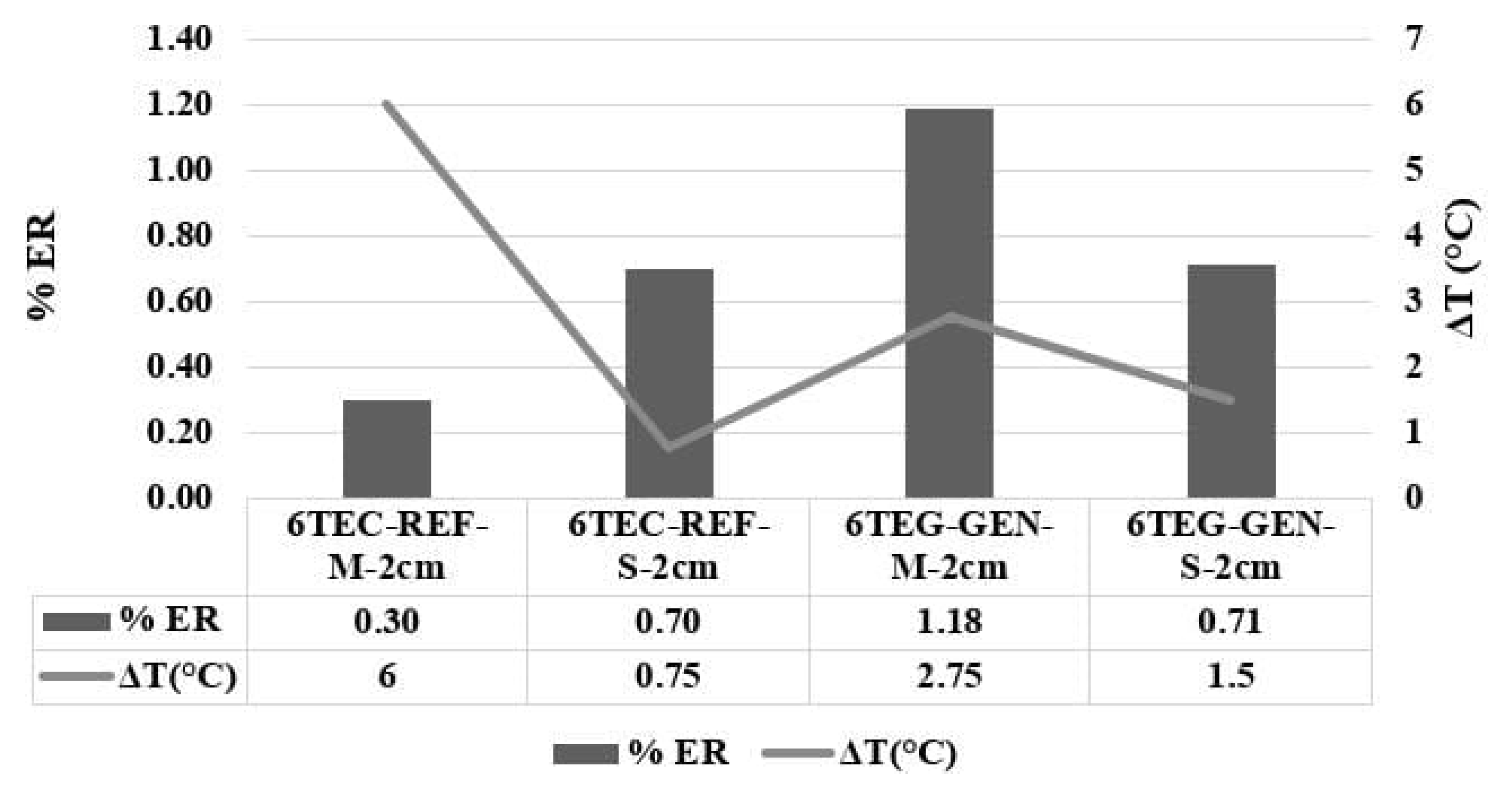
  • The maximum heat recovery efficiency was 1.18% for the 6TEG-GEN-M-2cm test, in which the SP 1848-27145 cells of thermoelectric generation in mixed connection were used. It is recommended for future work that a hybrid heat dissipation system be implemented that uses the recirculation of air or wastewater from industrial processes. This is necessary to increase the temperature delta and to obtain better performances of the modules.

Author Contributions

Conceptualization, H.A.C., C.E.A. and A.A.A.; methodology, H.A.C.; validation, M.A.C.; investigation, M.C., C.E.A. and H.A.C.; writing—original draft preparation, H.A.C. and M.C.; writing—review and editing, H.A.C. and M.A.C.; supervision, H.A.C.; project administration, H.A.C. and A.A.A.; funding acquisition, H.A.C. and A.A.A. All authors have read and agreed to the published version of the manuscript.

Funding

This research received financial support from the Colombia Scientific Program within the framework of the call Ecosistema Científico (Contract No. FP44842-218-2018).

Institutional Review Board Statement

Not applicable.

Informed Consent Statement

Not applicable.

Data Availability Statement

Data will be available upon request.

Acknowledgments

The authors gratefully acknowledge Universidad de Antioquia for the support in this project. The authors gratefully acknowledge the financial support provided by the Colombia Scientific Program within the framework of the call Ecosistema Científico (Contract No. FP44842- 218-2018).

Conflicts of Interest

The authors declare no conflict of interest.

References

  1. Colorado, H.A.; Mendoza, D.E.; Lin, H.-T.; Gutierrez-Velasquez, E. Additive Manufacturing against the Covid-19 Pandemic: A Technological Model for the Adaptability and Networking. J. Mater. Res. Technol. 2022, 16, 1150–1164. [Google Scholar] [CrossRef] [PubMed]
  2. International Energy Agency Electricity Generation by Source, World 1990–2019. Available online: https://www.iea.org/fuels-and-technologies/electricity#key-findings (accessed on 1 June 2022).
  3. Looney, B. Statistical Review of World Energy Globally Consistent Data on World Energy Markets and Authoritative Publications in the Field of Energy. Rev. World Energy Data. 2021, 70, 8–20. [Google Scholar]
  4. Zhang, L.; Li, H.; Lee, W.J.; Liao, H. COVID-19 and Energy: Influence Mechanisms and Research Methodologies. Sustain. Prod. Consum. 2021, 27, 2134–2152. [Google Scholar] [CrossRef] [PubMed]
  5. Rita, E.; Chizoo, E.; Cyril, U.S. Sustaining COVID-19 Pandemic Lockdown Era Air Pollution Impact through Utilization of More Renewable Energy Resources. Heliyon 2021, 7, e07455. [Google Scholar] [CrossRef] [PubMed]
  6. Gu, P.; Zheng, M.; Zhao, Q.; Xiao, X.; Xue, H.; Pang, H. Rechargeable Zinc–Air Batteries: A Promising Way to Green Energy. J. Mater. Chem. A Mater. 2017, 5, 7651–7666. [Google Scholar] [CrossRef]
  7. Lee, S.; Jeong, D.; Kim, C.; Lee, C.; Kang, H.; Woo, H.Y.; Kim, B.J. Eco-Friendly Polymer Solar Cells: Advances in Green-Solvent Processing and Material Design. ACS Nano 2020, 14, 14493–14527. [Google Scholar] [CrossRef] [PubMed]
  8. Colorado, S.A.; Colorado, H.A. Manufacturing of Zinc Oxide Structures by Thermal Oxidation Processes as Scalable Methods towards Inexpensive Electric Generators. Ceram. Int. 2017, 43, 15846–15855. [Google Scholar] [CrossRef]
  9. Li, Y.; Lu, J. Lightweight Structure Design for Wind Energy by Integrating Nanostructured Materials. Mater. Des. 2014, 57, 689–696. [Google Scholar] [CrossRef]
  10. MIT Energy Initiative. The Future of Nuclear Energy in a Carbon-Constrained World An Interdisciplinary MIT Study; MIT Energy Initiative: Boston, MA, USA, 2018. [Google Scholar]
  11. Zheng, X.F.; Liu, C.X.; Yan, Y.Y.; Wang, Q. A Review of Thermoelectrics Research-Recent Developments and Potentials for Sustainable and Renewable Energy Applications. Renew. Sustain. Energy Rev. 2014, 32, 486–503. [Google Scholar] [CrossRef]
  12. Castañeda, M.; Gutiérrez-Velásquez, E.I.; Aguilar, C.E.; Monteiro, S.N.; Amell, A.A.; Colorado, H.A. Sustainability and Circular Economy Perspectives of Materials for Thermoelectric Modules. Sustainability 2022, 14, 5987. [Google Scholar] [CrossRef]
  13. Papapetrou, M.; Kosmadakis, G.; Cipollina, A.; la Commare, U.; Micale, G. Industrial Waste Heat: Estimation of the Technically Available Resource in the EU per Industrial Sector, Temperature Level and Country. Appl. Therm. Eng. 2018, 138, 207–216. [Google Scholar] [CrossRef]
  14. Fang, H.; Xia, J.; Zhu, K.; Su, Y.; Jiang, Y. Industrial Waste Heat Utilization for Low Temperature District Heating. Energy Policy 2013, 62, 236–246. [Google Scholar] [CrossRef]
  15. Jouhara, H.; Olabi, A.G. Editorial: Industrial Waste Heat Recovery. Energy 2018, 160, 1–2. [Google Scholar] [CrossRef]
  16. Luo, D.; Wang, R.; Yan, Y.; Yu, W.; Zhou, W. Transient Numerical Modelling of a Thermoelectric Generator System Used for Automotive Exhaust Waste Heat Recovery. Appl. Energy 2021, 297, 117151. [Google Scholar] [CrossRef]
  17. Fernández-Yáñez, P.; Romero, V.; Armas, O.; Cerretti, G. Thermal Management of Thermoelectric Generators for Waste Energy Recovery. Appl. Therm. Eng. 2021, 196, 117291. [Google Scholar] [CrossRef]
  18. Kempf, N.; Saeidi-Javash, M.; Xu, H.; Cheng, S.; Dubey, M.; Wu, Y.; Daw, J.; Li, J.; Zhang, Y. Thermoelectric Power Generation in the Core of a Nuclear Reactor. Energy Convers Manag. 2022, 268, 115949. [Google Scholar] [CrossRef]
  19. Martín-Gómez, C.; Zuazua-Ros, A.; del Valle de Lersundi, K.; Sánchez Saiz-Ezquerra, B.; Ibáñez-Puy, M. Integration Development of a Ventilated Active Thermoelectric Envelope (VATE): Constructive Optimization and Thermal Performance. Energy Build. 2021, 231, 110593. [Google Scholar] [CrossRef]
  20. Jouhara, H.; Żabnieńska-Góra, A.; Khordehgah, N.; Doraghi, Q.; Ahmad, L.; Norman, L.; Axcell, B.; Wrobel, L.; Dai, S. Thermoelectric Generator (TEG) Technologies and Applications. Int. J. 2021, 9, 100063. [Google Scholar] [CrossRef]
  21. Nesarajah, M.; Frey, G. Thermoelectric Power Generation: Peltier Element versus Thermoelectric Generator. In Proceedings of the IECON 2016—42nd Annual Conference of the IEEE Industrial Electronics Society, Florence, Italy, 23–26 October 2016; pp. 4252–4257. [Google Scholar]
  22. Freire, L.O.; Navarrete, L.M.; Corrales, B.P.; Castillo, J.N. Efficiency in Thermoelectric Generators Based on Peltier Cells. Energy Rep. 2021, 7, 355–361. [Google Scholar] [CrossRef]
  23. Luo, D.; Wang, R.; Yu, W.; Zhou, W. A Novel Optimization Method for Thermoelectric Module Used in Waste Heat Recovery. Energy Convers Manag. 2020, 209, 112645. [Google Scholar] [CrossRef]
  24. Twaha, S.; Zhu, J.; Yan, Y.; Li, B. A Comprehensive Review of Thermoelectric Technology: Materials, Applications, Modelling and Performance Improvement. Renew. Sustain. Energy Rev. 2016, 65, 698–726. [Google Scholar] [CrossRef]
  25. Araiz, M.; Casi, Á.; Catalán, L.; Martínez, Á.; Astrain, D. Prospects of Waste-Heat Recovery from a Real Industry Using Thermoelectric Generators: Economic and Power Output Analysis. Energy Convers Manag. 2020, 205, 112376. [Google Scholar] [CrossRef]
  26. Dongxu, J.; Zhongbao, W.; Pou, J.; Mazzoni, S.; Rajoo, S.; Romagnoli, A. Geometry Optimization of Thermoelectric Modules: Simulation and Experimental Study. Energy Convers Manag. 2019, 195, 236–243. [Google Scholar] [CrossRef]
  27. Rocha, H.; Albuquerque, D.; Protásio, C. Measurement of Parameters and Degradation of Thermoelectric Modules. IEEE Instrum. Meas. Mag. 2017, 20, 13–19. [Google Scholar]
  28. Poon, S.J. Half Heusler Compounds: Promising Materials for Mid-to-High Temperature Thermoelectric Conversion. J. Phys. D Appl. Phys. 2019, 52, 493001. [Google Scholar] [CrossRef] [Green Version]
  29. Salvador, J.R.; Cho, J.Y.; Ye, Z.; Moczygemba, J.E.; Thompson, A.J.; Sharp, J.W.; König, J.D.; Maloney, R.; Thompson, T.; Sakamoto, J.; et al. Thermal to Electrical Energy Conversion of Skutterudite-Based Thermoelectric Modules. J. Electron. Mater. 2013, 42, 1389–1399. [Google Scholar] [CrossRef]
  30. Hong, M.; Chen, Z.-G.; Zou, J. Fundamental and Progress of Bi 2 Te 3 -Based Thermoelectric Materials. Chin. Phys. B 2018, 27, 048403. [Google Scholar] [CrossRef] [Green Version]
  31. Nguyen, N.Q.; Pochiraju, K.V. Behavior of Thermoelectric Generators Exposed to Transient Heat Sources. Appl. Therm. Eng. 2013, 51, 1–9. [Google Scholar] [CrossRef]
  32. Charilaou, K.; Kyratsi, T.; Louca, L.S. Design of an Air-Cooled Thermoelectric Generator System through Modelling and Simulations, for Use in Cement Industries. Mater. Today Proc. 2021, 44, 3516–3524. [Google Scholar] [CrossRef]
  33. Unite States Deparment of Energy. Energy Efficiency and Renewable Energy.Improvent Process Heating Sytem Performace: A Sourcebook for Industry, 2nd ed.; Unite States Department of Energy: Washington, DC, USA, 2007.
  34. Loaiza, A.; Colorado, H.A. Marshall Stability and Flow Tests for Asphalt Concrete Containing Electric Arc Furnace Dust Waste with High ZnO Contents from the Steel Making Process. Constr. Build. Mater. 2018, 166, 769–778. [Google Scholar] [CrossRef]
  35. Colorado, H.A.; Muñoz, A.; Monteiro, S.N. Circular Economy of Construction and Demolition Waste: A Case Study of Colombia. Sustainability 2022, 14, 7225. [Google Scholar] [CrossRef]
  36. Colorado, H.A.; Echeverri-Lopera, G.I. The Solid Waste in Colombia Analyzed via Gross Domestic Product: Towards a Sustainable Economy. Rev. Fac. Ing. 2020, 96, 51–63. [Google Scholar] [CrossRef]
  37. Jiménez, J.E.; Fontes Vieira, C.M.; Colorado, H.A. Composite Soil Made of Rubber Fibers from Waste Tires, Blended Sugar Cane Molasses, and Kaolin Clay. Sustainability 2022, 14, 2239. [Google Scholar] [CrossRef]
  38. Agudelo, G.; Palacio, C.A.; Neves Monteiro, S.; Colorado, H.A. Foundry Sand Waste and Residual Aggregate Evaluated as Pozzolans for Concrete. Sustainability 2022, 14, 9055. [Google Scholar] [CrossRef]
  39. Punin, W.; Maneewan, S.; Punlek, C. Heat Transfer Characteristics of a Thermoelectric Power Generator System for Low-Grade Waste Heat Recovery from the Sugar Industry. Heat Mass Transf. 2019, 55, 979–991. [Google Scholar] [CrossRef]
Figure 1. Mounting design of the TGS of 6 modules n. (a) Electrical interconnection of the TGS of 6 modules; (b) schematic configuration; (c) actual assembly.
Sustainability 15 03681 g001
Figure 2. Outline of the TGS made up of 6 thermoelectric modules in (a) serial connection and (b) mixed connection.
Sustainability 15 03681 g002
Figure 3. Basic diagram for the power generation of the TGS made up of 6 thermoelectric modules.
Sustainability 15 03681 g003
Figure 4. Diagram of the assembly of the experimental platform.
Sustainability 15 03681 g004
Figure 5. Results of electrical power vs. differential temperature for laboratory TGS tests of two thermoelectric modules (a) TEG- SP1848-2714SA; (b) TEC-12706.
Sustainability 15 03681 g005
Figure 6. Results of laboratory tests with TGS of 6 thermoelectric cells: electric voltage vs. differential temperature and electric current vs. differential temperature.
Sustainability 15 03681 g006
Figure 7. Thermography of the hot surface of the drying oven.
Sustainability 15 03681 g007
Figure 8. Results of (a) difference in temperature between the faces of the cell: (b) electrical voltage; (c) electrical power.
Sustainability 15 03681 g008
Figure 9. Heat recovery efficiency and ΔT.
Sustainability 15 03681 g009
Table 1. Technical specifications of the references of the thermoelectric modules.
SP1848-27145SA (TEG-GEN)TEC1-12706 (TEC-REF)
Cost (USD)3.50Cost (USD)3.05
Dimensions (mm)40 × 40 × 3.4Dimensions (mm)40 × 40 × 3.8
Maximum temperature difference (°C)100Max. temp. difference between faces (°C)66–75
Nominal current (mA)669 Maximum current (A)6.4
Maximum open circuit voltage (V)4.8 Maximum voltage (V)16.4
Nominal power (W)------Nominal power (W)72
Hot side temperature (°C)150Hot side temperature (°C)50–57
Thermal conductivity (W/cm.°C)1.6Thermal conductivity (W/cm.°C)1.2
Table 2. Design of experiments for the thermoelectric generator at the laboratory and industrial levels.
TGS DesignationLevel TestModule TypeNumber of ModulesConnection TypeDistance from Source
2TEG-GEN-S-10cmLaboratoryTEG-GEN2Serial10 cm
2TEG-GEN-P-5cmLaboratoryTEG-GEN2Parallel5 cm
2TEC-REF-S-10cmLaboratoryTEC-REF2Serial10 cm
2TEC-REF-S-5cmLaboratoryTEC-REF2Parallel5 cm
6TEG-GEN-S-2cmLaboratoryTEG-GEN6Serial2 cm
6TEG-GEN-M-2cmLaboratoryTEG-GEN6Mixed2 cm
6TEG-REF-S-2cmLaboratoryTEC-REF6Serial2 cm
6TEG-REF-M-2cmLaboratoryTEC-REF6Mixed2 cm
6TEG-GEN-S-5cmIndustryTEG-GEN6Serial5 cm
6TEG-GEN-M-5cmIndustryTEG-GEN6Mixed5 cm
6TEG-REF-S-5cmIndustryTEC-REF6Serial5 cm
6TEG-REF-M-5cmIndustryTEC-REF6Mixed5 cm
Table 3. Results of the maximum energy recovery values in laboratory tests on two thermoelectric cells at the laboratory level.
TGST. Cold (Tc) (°C)T. Hot (Th) (°C)Difference Temp (°K)Electrical Voltage (mV)Electrical Current (mA)Electrical Power (W)%ER
2TEG GEN P 5cm70.7593.0022.251068.00106.10113.313.38
2TEG GEN S 5cm69.2596.0026.75762.6075.5026.781.43
2TEG GEN P10cm64.5080.5016.00820.0080.8066.262.75
2TEG GEN S 10cm65.2584.2519.00521.0051.4057.580.94
2TEC REF P 5cm78.7596.2517.50506.4049.8025.221.43
2TEC REF S 5cm80.5105.7525.25256.0025.5020.130.26
2TEC REF P 10cm 68.2590.5022.25452.4044.507.560.90
2TEC REF S 10cm75.7590.0014.25279.0027.106.530.53
Table 4. Results obtained for the evaluation of heat recovery efficiency in laboratory tests with TGS of 6 thermoelectric cells.
TestΔT (°K)Pout (mW)QT (W)% ER
6TEC-REF-M-5cm16.36.744941.470.17
6TEC-REF-S-5cm15.31.994638.320.22
6TEG-GEN-M-5cm17.314.717815.530.29
6TEG-GEN-S-5cm35.74.8316,128.000.10
Table 5. Results obtained to evaluate heat recovery efficiency.
TESTΔT (°K)POUT (W)QT (W)% ER
6TEC-REF-M-2cm66.742273.680.30
6TEC-REF-S-2cm0.751.99284.210.70
6TEG-GEN-M-2cm2.7514.711242.351.18
6TEG-GEN-S-2cm1.54.83677.650.71
Disclaimer/Publisher’s Note: The statements, opinions and data contained in all publications are solely those of the individual author(s) and contributor(s) and not of MDPI and/or the editor(s). MDPI and/or the editor(s) disclaim responsibility for any injury to people or property resulting from any ideas, methods, instructions or products referred to in the content.

