You are currently viewing a new version of our website. To view the old version click .
Sustainability
  • Article
  • Open Access

12 February 2023

Construction and Cost Analysis of BladeBridges Made from Decommissioned FRP Wind Turbine Blades

,
,
,
,
,
,
,
and
1
Civil, Structural & Environmental Engineering, Munster Technological University, T12 P928 Cork, Ireland
2
School of Natural and Built Environment, Queen’s University Belfast, Belfast BT7 1NN, UK
3
School of Built Environment, Engineering & Computing, Leeds Beckett University, Leeds LS1 3HE, UK
4
School of Architecture, Georgia Institute of Technology, Atlanta, GA 30332, USA
This article belongs to the Section Sustainable Engineering and Science

Abstract

This paper describes repurposing projects using decommissioned wind turbine blades in bridges conducted under a multinational research project entitled “Re-Wind”. Repurposing is defined by the Re-Wind Network as the re-engineering, redesigning, and remanufacturing of a wind blade that has reached the end of its life on a turbine and taken out of service and then reused as a load-bearing structural element in a new structure (e.g., bridge, transmission pole, sound barrier, seawall, shelter). The issue of end-of-life of wind turbine blades is becoming a significant sustainability concern for wind turbine manufacturers, many of whom have committed to the 2030 or 2040 sustainability goals that include zero-waste for their products. Repurposing is the most sustainable end-of-life solution for wind turbine blades from an environmental, economic, and social perspective. The Network has designed and constructed two full-size pedestrian/cycle bridges—one on a greenway in Cork, Ireland and the other in a quarry in Draperstown, Northern Ireland, UK. The paper describes the design, testing, and construction of the two bridges and provides cost data for the bridges. Two additional bridges that are currently being designed for construction in Atlanta, GA, USA are also described. The paper also presents a step-by-step procedure for designing and building civil structures using decommissioned wind turbine blades. The steps are: project planning and funding, blade sourcing, blade geometric characterization, material testing, structural testing, designing, cost estimating, and construction.

1. Introduction

Wind turbine blades are made primarily of glass fibre reinforced polymer (GFRP) composite materials that are non-biodegradable and are only designed for a service life of 20–25 years. Once the blades have reached their end of life (EOL), they are decommissioned regardless of their condition. The issues associated with decommissioning a wind farm and how to dispose of the blades are complex [1]. The technologies being considered for blade EOL are reuse, repurposing, recycling, reclamation, co-processing, incineration, landfilling, and stockpiling [2]. Each of these needs to be evaluated with respect to their overall sustainability that includes the economic feasibility, environmental impact, and social acceptance [3]. At present, landfilling, incineration, and stockpiling are preferred by the wind industry due to their low cost. However, these options are becoming increasingly unacceptable to both the public and to regulators due to their harmful effects and unsustainable nature. A number of countries already prohibit landfilling blade waste. The scale of EOL blade waste makes it an especially concerning issue, as there will be an estimated cumulative total of 43 million tonnes of blade waste worldwide by 2050 if no blades are disposed of in the interim and are stockpiled. Europe and the United States will need to process a combined total of 41% of this waste [4,5].
To address the global issue of wind turbine blade waste, the Re-Wind Network (https://www.re-wind.info (accessed 28 December 2022)) was founded in 2017 as a partnership between universities in the United States (Georgia Institute of Technology (GT) and City University of New York (CUNY)), United Kingdom (Queen’s University Belfast (QUB)), and the Republic of Ireland (University College Cork (UCC)). The main goal of this research network is to investigate the use of decommissioned wind turbine blades in second-life structural applications. The team began the research in 2017 by identifying blades for use in a wind blade pedestrian bridge demonstration project. In 2018, the team studied the potential to develop a pedestrian bridge using a Vestas V27 blade, determined its mechanical and structural properties, and published the design and analysis results in the first BladeBridge paper in 2019 [6]. Work on the BladeBridge continued through a partnership between Georgia Institute of Technology (GT), University College Cork (UCC), and Munster Technological University (MTU), and the team constructed its first BladeBridge in Cork, Ireland in January 2022 [7] and its second BladeBridge in Draperstown, Northern Ireland, UK in April 2022. In addition to the BladeBridge work, the GT team has been investigating the application of decommissioned blades as power transmission poles. Several papers regarding the BladePole have been published [8,9], and a demonstration project is planned for construction in South Carolina, USA in 2023. The Re-Wind Network has proposed numerous repurposing solutions that can be found in the Re-Wind Fall 2022 Design Catalogue, Figure 1 [10].
Figure 1. Cover of the 2022 Re-Wind Design Catalogue.

2. Cork, Ireland BladeBridge

2.1. Planning, Funding, and Blade Sourcing

In 2020, the BladeBridge teams at GT and UCC developed a partnership with the structures laboratory at Munster Technological University (MTU). MTU and the local Cork County Council were able to identify a potential BladeBridge site on the Midleton–Youghal Greenway, which was under development by Cork County Council. The greenway was granted planning permission in 2019 and is funded under the Irish Government Department of Transport’s “Project Ireland 2040” initiative [11]. Once the BladeBridge site was confirmed, the team needed to source suitable decommissioned blades, both for testing and for use on the project. Everun Ltd., a Northern-Ireland based company specialising in wind energy asset management, donated eight LM 13.4 blades from Nordex N29 turbines to the team. While it sounds self-explanatory that blades need to be obtained before any repurposing design work can begin, obtaining decommissioned wind blades is not trivial, even though many blades are stockpiled. There are numerous reasons for this including existing decommissioning contracts, the waste status of the blades, transfer of ownership, proprietary blade data, sales price (if not donated), transportation, and possible liability. Testing of the blades and design of the bridge were conducted at the MTU structures laboratory in collaboration with the GT and UCC teams. The construction of the bridge was completed by local contractors and fabricators, with supervision from MTU and Cork County Council. The BladeBridge was completed in January 2022.

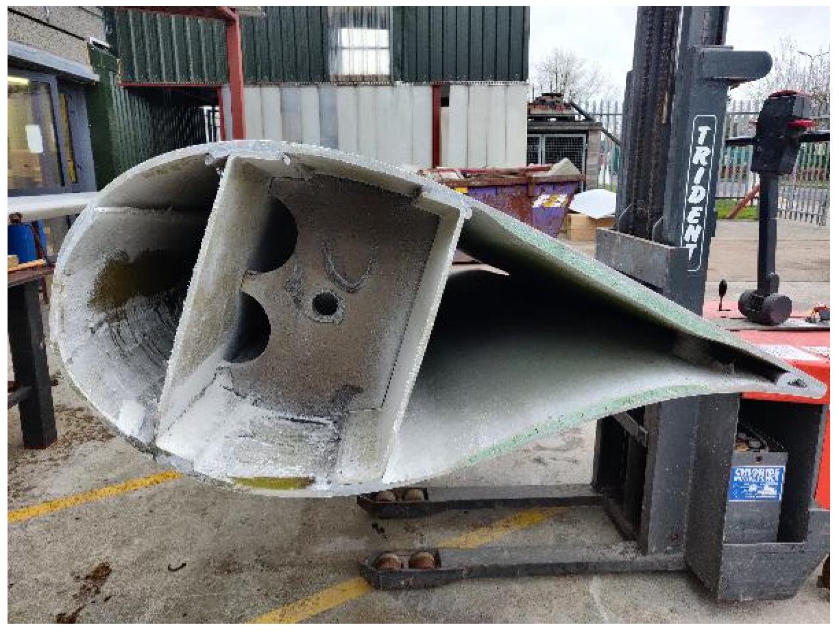
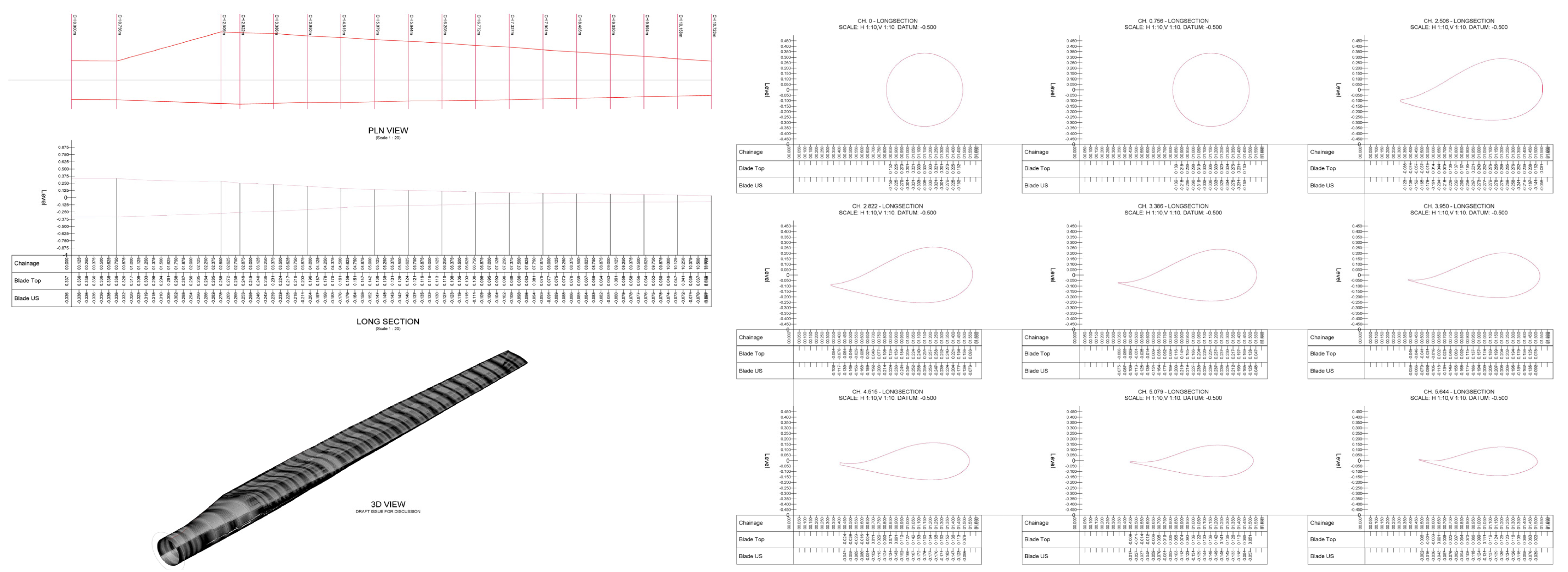
2.2. Geometric Characterization of the Wind Blade

In order to characterize the geometry of the LM 13.4 blade, LiDAR scanning and physical measurements from cut sections of sacrificial blades were performed. LiDAR scanning was conducted on the full blades at the Everun yard in Belfast prior to moving them and then again at QUB and at MTU. Structural and finite element models of the blade from 3D point clouds obtained from the LiDAR scans using a methodology developed at Georgia Institute of Technology and known as the BladeMachine [12,13]. At QUB, the blade was cut into one meter long segments and each segment was scanned, as shown in Figure 2.
Figure 2. LiDAR scanning of one meter long segments.
Physical measurements were also taken of the cut sections to develop a full three dimensional model of the blade. A portion of the cross-section of the LM 13.4 wind blade near the maximum chord length used in the Cork BladeBridge along with the naming convention used for the different airfoil components is shown in Figure 3. The blade was manufactured in two halves and adhesively bonded together at the leading (rounded) edge and the trailing (sharp) edge. Two channel shaped webs were bonded in the interior to create the multicell structure seen in Figure 2 and Figure 3. The trailing edge panels were sandwich panels consisting of two thin skins and a foam core. The interior cross-diaphragms seen were provided to support a cable used to control a hydraulic brake at the end of the blade. All of the composite materials used were glass fibre reinforced epoxy.
Figure 3. Cross-section of the LM 13.4 blade at maximum chord.
Figure 4 shows the external geometry and the cross-sectional airfoil shapes of the LM 13.4 blade obtained from a LiDAR scan at MTU. Only the first 11 m of the blade was used to construct the bridge. The 2.4 m long aerodynamic brake typically attached to the end of the blade was not recovered from Everun Ltd. and was not used or characterized.
Figure 4. AutoCAD drawings of the blade geometry and blade airfoil cross-sections along the length.

2.3. Material Testing

Resin burnout tests were conducted in accordance with ASTM D2584 [14] in order to determine the laminate properties of the wind blade’s FRP material. The fibre volume fraction in the primarily unidirectional glass rovings in the spar cap was between 0.38 and 0.4. Tensile and compressive tests, conducted in accordance with ASTM D3039 [15] and ASTM D3410 [16], were also performed on both the spar cap and web material. The longitudinal modulus, longitudinal tensile strength, and longitudinal compressive strength of the spar cap were 27.5 GPa, 342 MPa, and 415 MPa, respectively. Ultimate longitudinal failure strains were calculated from the linear behaviour to be 0.0124 in tension and 0.0150 in compression, respectively. The transverse tensile strength and transverse compressive strength were 16 MPa and 72 MPa, respectively. The transverse modulus was not measured for the spar cap material. The longitudinal modulus, longitudinal tensile strength, and longitudinal compressive strength of the primarily biaxial glass fabric web channels were 10.0 GPa, 207 MPa, and 164 MPa, respectively. The transverse strengths and the transverse modulus was not measured for the web material. Further details of the material architecture and results of the material testing can be found in [17].

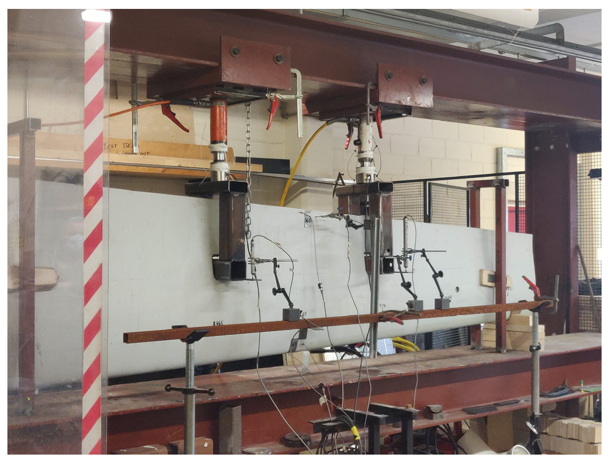
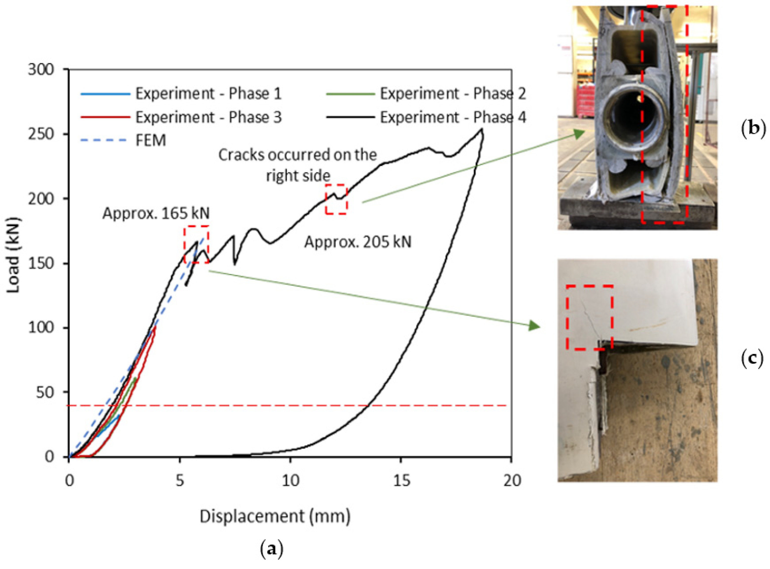
2.4. Structural Testing

The load–deflection behaviour and failure modes of the wind blade in edgewise bending was determined in a full-scale four-point bending test of a 4 m portion of the blade at the MTU structures laboratory, as shown in Figure 5. Vertical displacements were measured at the two load points and the maximum tensile and compressive strains at midspan were measured using bonded strain gages at the top and bottom of the section, as seen in Figure 5. The test section reached a maximum total load of 87.2 kN with a deflection at the loading points of 18.5 mm. Failure was due to crushing at the right support and separation of the webs from the spar caps. The load versus midspan deflection and load versus tensile and compressive strains are shown in Figure 6 and Figure 7. The strains were well below the ultimate strains at failure, confirming that flexural failure did not occur. No local buckling was observed in the narrow trailing edge of the blade, which was subjected to compressive stress of approximately 113 MPa when the specimen failed at the support. Based on these test results, the design team was confident that the blade would be able to carry the design service loads with a considerable factor of safety. Further details of the testing can be found in [17].
Figure 5. Structural testing of the LM 13.4 wind blade in the MTU structures laboratory.
Figure 6. Load versus midspan deflection.
Figure 7. Load versus (a) maximum tensile strain and (b) maximum compressive strain at midspan.

2.5. Structural Design

The bridge was designed for the loadings described in Eurocode 1 [18], which specifies a pedestrian loading of 5 kN/m2. An accidental vehicle load case comprising a 12 tonne vehicle specified by the Cork County Council was also used. The structural design of the BladeBridge involved detailed designs of the connections between the transverse beams and the blades as well as the concrete abutment capping beams holding the blades at both ends. The bridge was 6.15 m long with a clear span of 4.7 m and a width of 4.95 m with a skew of 14°. Masonry abutments from an earlier bridge dating from the late 1800s were rehabilitated and reused in the new bridge with cast-in-place concrete capping beams. The connections, transverse beams, and deck were galvanized steel. The connections were bolted directly into the spar cap using blind bolts. The reinforced concrete capping beams at the abutments were custom designed in order to cradle the root and airfoil ends of the blades, with the remainder of the blade tips being embedded into the greenway pavement. Further details regarding the structural design of the Cork BladeBridge can be found in [19].

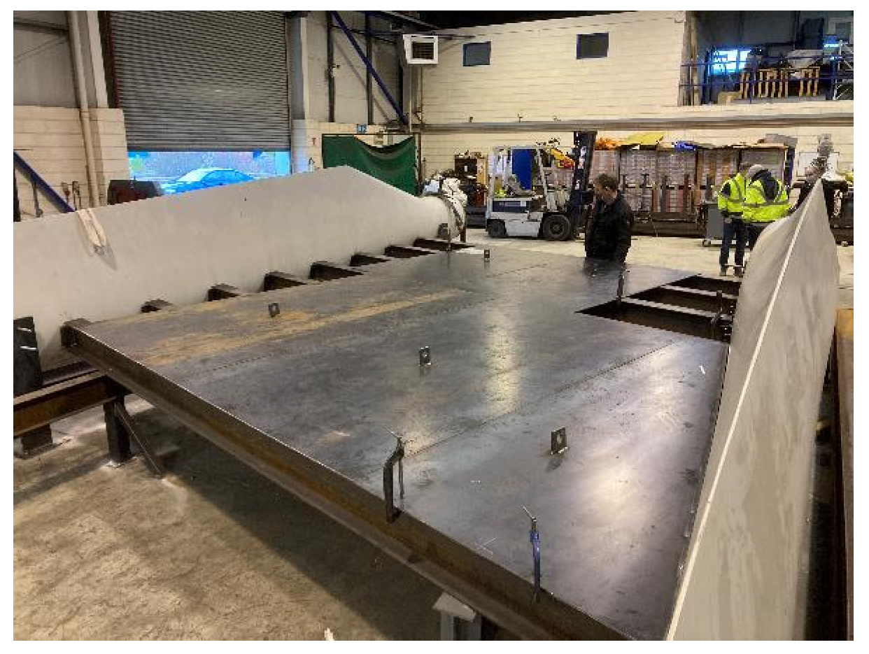
2.6. Fabrication and Installation

Fabrication of the bridge was performed by A.R. Brownlow Ltd., a local fabricator in Cork, Ireland, under the supervision of the MTU design team led by the lead author in late 2021. Figure 8 shows the bridge during fabrication. After being fully assembled at the fabricators, it was then disassembled, the steel sections galvanized, and then reassembled and installed on the Midleton–Youghal Greenway site in January 2022 by A.R. Brownlow Ltd. and civil engineering contractor Lemac Ltd. Assembly on site took approximately half a day. The cradle anchorages were cast into the concrete capping beams at an earlier stage so that the turbine blades could be installed directly from the delivery lorry (using a lorry mounted crane) and fixed at the correct level and orientation (see Figure 9). In Figure 9, the bespoke steel web cleats (“fins”) connected to the blade with blind bolts used to attach the floor beams can been seen. This allowed for the rapid assembly of the cross girders, bracing, and deck plate.
Figure 8. Fabrication and assembly of the Cork BladeBridge at the fabricator.
Figure 9. BladeBridge during assembly showing the cradles supporting the blades (prior to installing all the deck beams and plates).
On completion of the deck assembly, reinforced concrete piers were added to the capping beams to encase the cradle anchorages and an approach slab was constructed, as shown in Figure 10.
Figure 10. BladeBridge following installation on the Midleton to Youghal Greenway.

2.7. Material and Labour Costs

Prior to the construction and during the negotiation phase of a project, a cost estimate typically needs to be performed for a repurposed structure. For the case of the Cork BladeBridge, this was estimated to be approximately EUR 35,000 based on the costs of a comparable greenway bridge using concrete and steel previously constructed in Ireland.
The actual (initial) costs of the materials and labour for the Cork BladeBridge are shown in Table 1. These costs do not include the one-time costs of testing or the design costs, which were approximately EUR 12,000. Future BladeBridges built with the LM 13.4 m blades will not need testing or extensive redesign.
Table 1. Material and labour costs for the Cork BladeBridge.
The life cycle costs (LCC) were also calculated and compared with the costs of a similar bridge using steel girders in place of the wind blades [20]. The LCC showed that the BladeBridge would be less expensive than a conventional steel girder bridge over an assumed 60 year life span. This was primarily due to lower maintenance costs for the FRP composite wind blades over the lifetime. In addition, a life cycle assessment (LCA) using SimaPro was performed [21] and it was demonstrated that the BladeBridge would perform better environmentally than the comparable steel girder bridge. Both the LCC and the LCA were important aspects of the repurposing project and are recommended for all repurposing projects to help convince prospective clients of the sustainability of these projects.

3. Draperstown, Northern Ireland BladeBridge

3.1. Planning, Funding, and Blade Sourcing

The second BladeBridge was one that was to be built for experimental purposes only and will be tested to failure in the summer of 2023. Similar to the Cork BladeBridge, the wind turbine blades were donated by Everun Ltd. and were LM 13.4 blades from Nordex N29 turbines. Four blades were transported to a quarry near Draperstown, Magherafelt, Northern Ireland and one to Queen’s University Belfast. The bridge was constructed in the quarry on flat ground. As such, the “abutments” were blocks of concrete whose purpose was not just to provide a support for the end of the blades, but to also elevate the blades above the ground to create a bridge structure. Funding was provided by the primary U.S.–Ireland Tripartite grant (see Funding below.)

3.2. Structural Testing

A three-point bend test was carried out on a one meter long, coped section of the wind blade extracted at a distance of about 9 m from its root. Sections of the leading edge under the bottom shear webs at the right and left ends were removed and supported, as seen in Figure 11. Steel threaded rods with nuts at each end were inserted through the section to prevent separation of the web channels from the spar caps due to outward bowing of the side walls due to in-plane compression, as seen in prior tests at MTU [17]. Three linear variable differential transformers (LVDTs) were attached to the left end, right end, and mid-span of the section, as shown in Figure 11. LVDT 1 was mounted in the mid-span of the leading edge in the section while LVDT 3 and LVDT 2 were located on the top shear web at a distance of approximately 50 mm from the edge. Simple support conditions were achieved by means of steel rollers located between two steel plates. The tested section was loaded at mid-span at a rate of 0.03 mm/min.
Figure 11. Three-point bending test set-up for 1 m wind blade section.
Figure 12a shows the relationship between the load and midspan deflection of the section as well as the failure modes. The dashed red line at approximately 45 kN indicates the design service load. The load was applied into four phases with the maximum load at each phase ranging from about 30 to 250 kN. In the last phase, the load was applied continuously until failure occurred. In the first three phases, the loading–unloading behaviour was similar and showed some hysteresis. In the last phase, progressive failure was observed. At approximately 165 kN, a hairline crack developed at the corner of the right coped section (Figure 12c). At 205 kN, a separation occurred in the adhesive bond between the spar cap and shear webs at the right end (Figure 12b). This separation was arrested by the threaded rods and nuts and did not propagate into the interior of the specimen. This allowed it to continue to resist additional load up until 250 kN, when the load was removed. A linear elastic finite element method (FEM) model was constructed in ABAQUS using the geometry and material properties determined from coupon testing. The model showed good correlation with the test results up until the initiation of the first failure at 165 kN. Based on these test results, the design team was confident that the blade would be able to carry the design service loads with a considerable factor of safety.
Figure 12. (a) Load and mid-span deflection curves for the three-point bending test, (b) debonding failure at 205 kN, (c) cracking at 165 kN.

3.3. BladeBridge Design

Figure 13 shows the design of the Draperstown BladeBridge with a clear span of 6 m and a deck width of 2 m. Steel angles were bolted onto the wind blades. Timber joists were supported on these to carry the timber deck. Threaded rods, needed for attaching the steel angles, were inserted at the height of the top web to prevent any separation of the spar cap from the webs. The leading edge was embedded in concrete abutments, which was filled in the interior up to mid-height of the spar cap. Polystyrene blocks were placed inside the blade at the edge of abutment to prevent the concrete filling the rest of the blade.
Figure 13. Design sketch for the Draperstown BladeBridge.

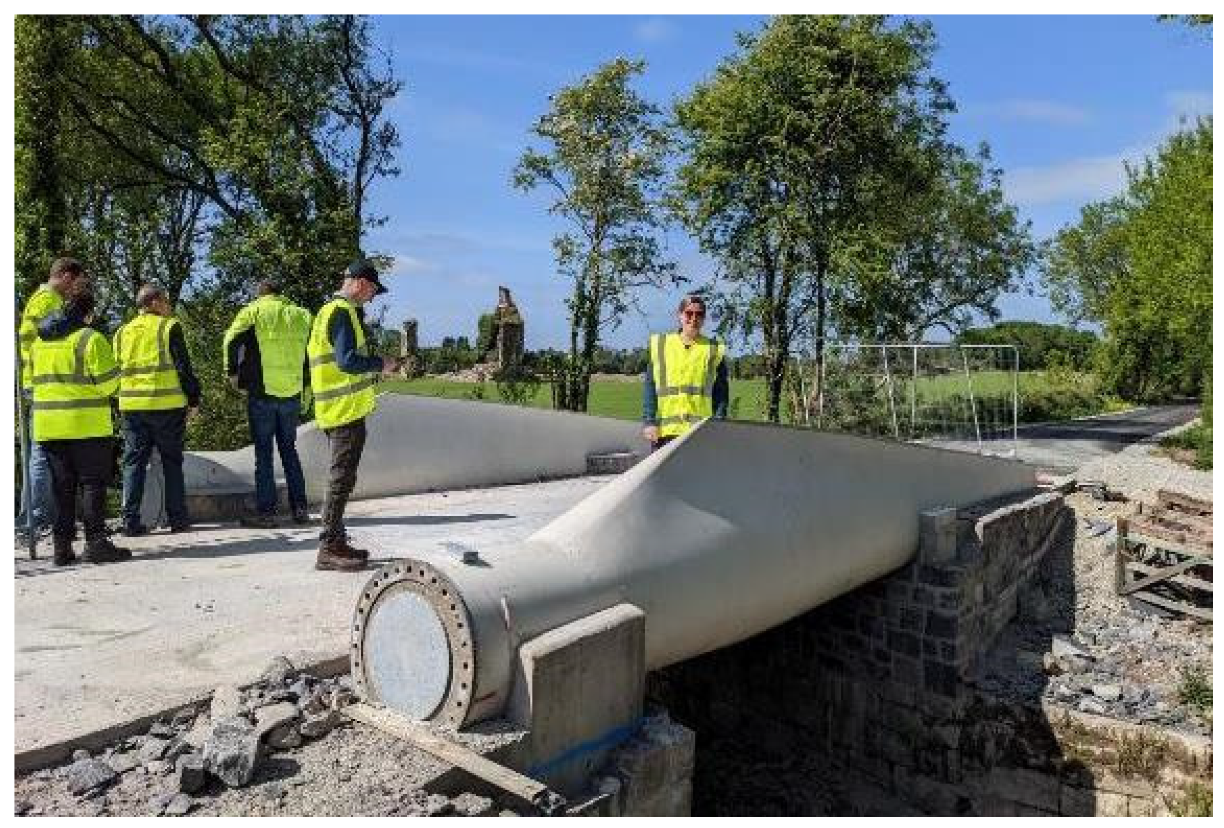
3.4. Fabrication and Installation

The bridge was fabricated and constructed on the site at the quarry in the course of four days. All the construction work was performed by the technical staff at Queen’s University Belfast. Figure 14 shows the BladeBridge during fabrication and after construction.
Figure 14. (a) Concrete placed inside the blade at the abutment and details of the deck structure, and (b) the BladeBridge after construction was completed.

3.5. Material and Labour Costs

The costs of the materials and labour for the Draperstown BladeBridge are shown in Table 2. These costs do not include the testing or the design costs, which were funded by the primary research U.S.–Ireland Tripartite grant (see Funding below).
Table 2. Material and labour costs for the Northern Ireland BladeBridge.

4. Atlanta, USA BladeBridges

Following the successes of the BladeBridges in Cork and Northern Ireland, the Georgia Tech Re-Wind team is now pursuing a new BladeBridge project in the United States at Beaverbrook Park, Atlanta, Georgia using 45 m long blades. The expanded park trail will loop through an existing creek behind the park and cross it at two locations. Re-Wind has proposed installing two BladeBridges rather than traditional timber pedestrian bridges. The bridge spans are anticipated to be about 15 m, considerably longer than the bridges previously built in Ireland. A rendering is shown in Figure 15. The Re-Wind team is providing all of the design services for the bridges as well as the completed bridge superstructure (excluding the deck and foundations). Due to the site constraints, the team is exploring several different design options that optimize the constructability and user experience. In addition to the classic BladeBridge design used previously, another design option includes a fully cantilevered bridge with supports only at one end of the creek, while a third option only utilises one blade with a braced and cantilevered deck. Currently, the research team is assessing the structural feasibility of each option, and will then move forward with full-scale testing of the selected bridge design.
Figure 15. Rendering of proposed BladeBridge for Beaverbrook Park, Atlanta, Georgia, USA.

5. Conclusions

Over the past five years, the Re-Wind Network has conducted detailed research into the repurposing of decommissioned wind turbine blades as a sustainable end-of-life technology that will prevent landfilling or incineration. The work has now developed into the delivery of public infrastructure created from repurposed wind blades with BladeBridges constructed in Ireland and Northern Ireland and further BladeBridges planned for North America. This paper presented physical evidence that bridges can be readily constructed using decommissioned wind turbine blades and that they are economical. The paper also provides a step-by-step procedure for building BladeBridges that includes project planning and funding, blade sourcing, blade geometric characterisation, material testing, structural testing, designing, cost estimating and constructing. These steps need to be included in any attempt to build civil infrastructure from repurposed wind turbine blades.

Author Contributions

Conceptualisation, K.R., M.S., T.R.G., A.N., P.L., A.H. and L.C.B.; Data curation, K.R., T.R.G., A.N., A.H. and L.C.B.; Formal analysis, K.R., M.S., T.R.G., A.H. and L.C.B.; Funding acquisition, K.R., T.R.G., P.L. and L.C.B.; Investigation, K.R., M.S., T.R.G., Z.Z., A.N., P.L., A.H., K.M. and L.C.B.; Methodology, K.R., A.N., A.H., K.M. and L.C.B.; Project administration, K.R., T.R.G., P.L. and L.C.B.; Resources, K.R., T.R.G., P.L., K.M. and L.C.B.; Software, T.R.G.; Supervision, K.R., M.S., T.R.G., P.L., K.M. and L.C.B.; Validation, A.H.; Visualisation, Z.Z., A.H. and L.C.B.; Writing—original draft, K.R., M.S., Z.Z., A.N., P.L., A.H. and L.C.B.; Writing—review & editing, P.L. and L.C.B. All authors have read and agreed to the published version of the manuscript.

Funding

Support for this research was provided by the National Science Foundation (NSF) under grants 2016409, 1701413, and 1701694; by InvestNI/Department for the Economy (DfE) under grant USI-116, and by Science Foundation Ireland (SFI) under grant 16/US/3334 in part under the U.S.–Ireland Tripartite research program. Financial support was also provided by Munster Technological Institute (MTU).

Institutional Review Board Statement

Not applicable.

Data Availability Statement

The data presented in this study are available on request from the corresponding author or are available in referenced papers by the authors.

Acknowledgments

Support from Re-Wind partners in Ireland (Cork County Council, MTU, Civil and Structural Engineering Advisors Ltd., Everun, Lemac Ltd., AR Brownlow Ltd.), and in the U.S. (Siemens Gamesa Renewable Energy (SGRE), ENEL Green Power, Logisticus, and Hubbell Power Systems) is acknowledged. This work would not have been possible without the support and dedication of the laboratory staff at MTU (Jim Morgan, Liam Jones and, Maggie Shorten) and at QUB (James Laing, Desmond Hill and Dan Reid). Contributions to early work on the BladeBridge concept by Jian Fei Chen and Raj Suhail are also recognised.

Conflicts of Interest

The authors declare no conflict of interest.

References

  1. Bank, L.C.; Delaney, E.; Mckinley, J.; Gentry, T.R.; Leahy, P. Defining the Landscape for Wind Blades at the End of Service Life. CompositesWorld. 2021. Available online: https://www.compositesworld.com/articles/defining-the-landscape-for-wind-blades-at-the-end-of-service-life (accessed on 28 December 2022).
  2. Gentry, T.R.; Al-Haddad, T.; Bank, L.C.; Arias, F.R.; Nagle, A.; Leahy, P. Structural Analysis of a Roof Extracted from a Wind Turbine Blade. J. Arch. Eng. 2020, 26, 04020040. [Google Scholar] [CrossRef]
  3. Deeney, P.; Nagle, A.J.; Gough, F.; Lemmertz, H.; Delaney, E.L.; McKinley, J.M.; Graham, C.; Leahy, P.G.; Dunphy, N.P.; Mullally, G. End-of-Life alternatives for wind turbine blades: Sustainability Indices based on the UN sustainable development goals. Resour. Conserv. Recycl. 2021, 171, 105642. [Google Scholar] [CrossRef]
  4. Liu, P.; Barlow, C.Y. Wind turbine blade waste in 2050. Waste Manag. 2017, 62, 229–240. [Google Scholar] [CrossRef] [PubMed]
  5. Bank, L.C.; Arias, F.R.; Yazdanbakhsh, A.; Gentry, T.R.; Al-Haddad, T.; Chen, J.-F.; Morrow, R. Concepts for Reusing Composite Materials from Decommissioned Wind Turbine Blades in Affordable Housing. Recycling 2018, 3, 3. [Google Scholar] [CrossRef]
  6. Suhail, R.; Chen, J.-F.; Gentry, T.R.; Tasistro-Hart, B.; Xue, Y.; Bank, L.C. Analysis and Design of a Pedestrian Bridge with Decommissioned FRP Windblades and Concrete. In Proceedings of the 14th International Symposium on Fiber-Reinforced Polymer Reinforcement of Concrete Structures (FRPRCS), Belfast, UK, 4–7 June 2019; IIFC: Belfast, UK; pp. 1–5. Available online: https://www.re-wind.info/product/2019/6/10/analysis-and-design-of-a-pedestrian-bridge-with-decommissioned-frp-windblades-and-concrete (accessed on 28 December 2022).
  7. Nehls, G. Re-Wind Network Successfully Installs Repurposed Wind Blade Pedestrian Bridge. CompositesWorld. 2022. Available online: https://www.compositesworld.com/news/re-wind-network-successfully-installs-repurposed-wind-blade-pedestrian-bridge (accessed on 20 October 2022).
  8. Al-Haddad, T.; Alshannaq, A.; Bank, L.; Bermek, M.; Gentry, R.; Henao-Barragan, Y.; Li, S.; Poff, A.; Respert, J.; Woodham, C. Strategies for Redesigning High Performance FRP Wind Blades as Future Electrical Infrastructure. In Proceedings of the ARCC-EAAE 2022 International Conference-Resilient City: Physical, Social, and Economic Perspectives, Miami, FL, USA, 2–5 March 2022; pp. 282–288. Available online: http://www.arcc-arch.org/wp-content/uploads/2022/09/ARCC-EAAE-2022_Proceedings_Digital-Version.pdf (accessed on 28 December 2022).
  9. Alshannaq, A.A.; Bank, L.C.; Scott, D.W.; Gentry, T.R. Structural Analysis of a Wind Turbine Blade Repurposed as an Electrical Transmission Pole. J. Compos. Constr. 2021, 25, 04021023. [Google Scholar] [CrossRef]
  10. McDonald, A.; Kiernicki, C.; Bermek, M.; Zhang, Z.; Poff, A.; Kakkad, S.; Lau, E.; Arias, F.; Gentry, R.; Bank, L. Re-Wind Design Catalog Fall 2022. Available online: https://doi.org/10.13140/RG.2.2.24487.42401 (accessed on 28 December 2022).
  11. Cork County Council. Midleton Youghal Greenway. 2022. Available online: https://www.corkcoco.ie/en/community-safety-education-roads-motor-tax/midleton-youghal-greenway (accessed on 28 December 2022).
  12. Tasistro-Hart, B.; Al-Haddad, T.; Bank, L.C.; Gentry, R. Reconstruction of Wind Turbine Blade Geometry and Internal Structure from Point Cloud Data. In Proceedings of the 2019 ASCE International Conference on Computing in Civil Engineering (i3CE 2019), Atlanta, GA, USA, 17–19 June 2019; pp. 130–137. [Google Scholar]
  13. Kiernicki, C.; Kakkad, S.D.; Bermek, M.S.; Gentry, T.R. A Digital Process for Reconstructing Wind Turbine Blade Geometry from Point Cloud Data. In Proceedings of the 5th International Conference on Structures and Architecture, Aalborg, Denmark, 6–8 July 2022. [Google Scholar]
  14. ASTM D2584; Standard Test Method for Ignition Loss of Cured Reinforced Resins. ASTM International: West Conshohocken, PA, USA, 2018.
  15. ASTM D3039; Standard Test Method for Tensile Properties of Polymer Matrix Composite Materials. ASTM International: West Conshohocken, PA, USA, 2017.
  16. ASTM D3410; Standard Test Method for Compressive Properties of Polymer Matrix Composite Materials with Unsupported Gage Section by Shear Loading. ASTM International: West Conshohocken, PA, USA, 2016.
  17. Ruane, K.; Zhang, Z.; Nagle, A.; Huynh, A.; Alshannaq, A.; McDonald, A.; Leahy, P.; Soutsos, M.; McKinley, J.; Gentry, R.; et al. Material and Structural Characterization of a Wind Turbine Blade for Use as a Bridge Girder. Transp. Res. Rec. J. Transp. Res. Board 2022, 2676, 354–362. [Google Scholar] [CrossRef]
  18. IS EN 1991-2:2003+NA:2009; Eurocode 1: Actions on Structures—Part 2: Traffic Loads on Bridges (Inc. National Annex to IS EN 1991-2:2003). National Standards Authority of Ireland: Dublin, Ireland, 2009.
  19. Zhang, Z.; Ruane, K.; Huynh, A.; McDonald, A.; Leahy, P.; Alshannaq, A.; Gentry, T.R.; Nagle, A.; Bank, L.C. BladeBridge-Design and Construction of a Pedestrian Bridge using Decommissioned Wind Turbine Blades. In Proceedings of the 5th International Conference on Structures and Architecture, Aalborg, Denmark, 6–8 July 2022. [Google Scholar]
  20. Nagle, A.J. Sustainability Assessment of the Repurposing of Wind Turbine Blades. Ph.D. Thesis, School of Engineering & Architecture, Environmental Research Institute University, College Cork, Cork, Ireland, 2022. [Google Scholar]
  21. Nagle, A.J.; Ruane, K.; Gentry, T.R.; Bank, L.C.; Dunphy, N.; Mullally, G.; Leahy, P.G. Life Cycle Sustainability Assessment of a Pedestrian Bridge Made from Repurposed Wind Turbine Blades. In Proceedings of the Civil Engineering Research in Ireland 2022, Dublin, Ireland, 25–26 August 2022; Available online: http://cerai.net/page/15/past-conferences/index.html (accessed on 28 December 2022).
Disclaimer/Publisher’s Note: The statements, opinions and data contained in all publications are solely those of the individual author(s) and contributor(s) and not of MDPI and/or the editor(s). MDPI and/or the editor(s) disclaim responsibility for any injury to people or property resulting from any ideas, methods, instructions or products referred to in the content.

Article Metrics

Citations

Article Access Statistics

Multiple requests from the same IP address are counted as one view.