Article

WAMS-Based Fuzzy Logic PID Secondary Voltage Control of the Egyptian Grid

1
Department of Electrical Power and Machines Engineering, Helwan University, Cairo 11792, Egypt
2
Electromechanics Engineering Department, Heliopolis University, Cairo 11785, Egypt
*
Author to whom correspondence should be addressed.
Sustainability 2023, 15(4), 3338; https://doi.org/10.3390/su15043338
Submission received: 29 November 2022 / Revised: 1 February 2023 / Accepted: 9 February 2023 / Published: 11 February 2023

Abstract

:
This paper presents the application of fuzzy logic PID secondary voltage control to the Egyptian power system model. The study included tertiary voltage control, Wide Area Measurement System (WAMS) configuration, a selection of pilot buses, and fuzzy logic PID secondary voltage control to improve the system performance. The secondary voltage control was applied using a fuzzy PID coordinated controller, a reactive power integral controller, Automatic Voltage Regulators (AVRs), and regional generators. The tertiary voltage control was implemented based on the optimal power flow to maximize the reactive power reserve. A novel optimization technique is presented to select pilot buses based on different operating conditions and compared to other techniques. The optimal WAMS configuration included the best allocation of Phasor Measurement Units (PMUs), Phasor Data Concentrators (PDCs), and the required communication infrastructure considering geographical regions with minimum cost. The Egyptian power grid considering 500/220 kV level is simulated by using DIgSILENT software to perform static and dynamic analyses, while the WAMS optimization problems and fuzzy logic PID controller design are performed by employing MATLAB software.

1. Introduction

The operation and control of modern power systems face increasingly complex challenges [1,2]. If a power grid is subjected to an unsecured disturbance, the voltage may decline within a few minutes dramatically and monotonically. If this decrease is too pronounced, the system integrity may become endangered, and the protection system may trip generation, transmission, or loads. This degradation process may eventually lead to a partial or full blackout due to voltage collapse [3]. Therefore, voltage control [4] is an essential requirement to preserve power system integrity.
In electrical power systems, there are three hierarchical voltage control levels. These are divided as follows: (1) the Primary Voltage Control (PriVC) level, (2) the Secondary Voltage Control (SecVC) level, and (3) the Tertiary Voltage Control (TerVC) level [5,6]. PriVC aims to control the voltage magnitude of the buses where the reactive power sources are installed, such as synchronous generators, synchronous condensers, Static Var Compensators (SVCs), or Static Compensators (STATCOMs). The voltage measurements used in this control level are taken locally [6]. The function of the SecVC is to provide voltage control of a pilot busbar in a control region. The pilot busbar is selected as a load bus that has the highest sensitivity. This control level is normally performed by using hardware that leads to adjusting the reference point of the PriVC, which is located in the same region as the pilot bus, at a speed slower than that of the PriVC control level. SecVC also determines the voltage control regions and indicates their association with each load bus. TerVC determines the optimal reference values of the load buses’ voltage magnitudes in the grid [7]. The optimal values may be determined by using the Optimal Power Flow (OPF) technique to achieve a certain objective function, such as minimal power loss, minimal load shedding, or maximizing the reactive power reserve. TerVC has a time range from half an hour to a complete hour to be periodically performed [8].
Secondary voltage control has been explored in many recent research works. In [8], a decentralized control scheme for the coordinated SecVC of large power networks is presented. A model predictive controller for each area of the power grid was designed. It can modify the set points of reactive power compensators that are participating in the SecVC scheme. In [9], an enhanced worst-case design of SecVC was performed, employing the maximum likelihood approach. As power system operating conditions continuously change, the SecVC should be flexible to cope with those changes and provides optimal set points that relate to the entire grid conditions [10].
An important factor for the proper operation of a SecVC is to carefully select the pilot bus [4]. In [11], the problem of pilot bus selection was solved based on the singular decomposition of the reduced Jacobian matrix with the voltage security margin index. In [12], the pilot bus selection was based on a stochastic multi-objective optimization problem considering normal operating conditions.
The Supervisory Control and Data Acquisition (SCADA) system has been widely used in the last century to transfer data on a point-to-point basis in power grids worldwide. In the era of green and smart grids, more states are present and a higher speed for data transfer is required, so Wide Area Measurement Systems (WAMS) are replacing SCADA. WAMS mainly consist of Phasor Measurement Units (PMUs) and associated communication devices. Many research papers in the field of WAMS configuration have focused on determining the optimal placement of PMUs in power grids that could drive the grid to be fully visible with minimum cost, but ignoring the communication devices cost. In [13], the target was to develop a full wide area measurement system configuration for standard power grids without considering the real geographical regions. In [14], a network model-free wide-area voltage control strategy is presented using PMUs. In [15], a proposed method for the coordinated SecVC of an HVDC system and offshore wind farm is presented. The aim was to minimize real-time voltage fluctuations throughout the offshore grid.
Applications of SecVC have been recently developed for microgrids. A distortion-based potential game strategy for SecVC in microgrids is presented in [16]. Nonlinear multiple models of adaptive SecVC for microgrids are described in [17]. A proposed method is presented in [18] to design a distributed SecVC based on an extended-state Kalman-Bucy filter and fast terminal sliding mode control for the resilient operation of an islanded microgrid with inverter-based distributed generators. In [19], a proposed unfalsified switching adaptive voltage control method was developed for the SecVC of islanded microgrids considering uncertainties. An optimally distributed control methodology for secondary frequency and voltage regulation in a microgrid is presented in [20]. A coordinated PID-SecVC of a power system based on the genetic algorithm is presented in [21]. Coordinated SecVC and PriVC in multi-machine power systems were developed in [22] using a complex-valued encoding dragonfly algorithm and artificial emotional reinforcement learning techniques. A proposed SecVC method incorporating compressive sensing and morphology singular entropy for a multi-area power system is introduced in [23]. A morphological median filter is used to reduce noise from the output of the PMUs. A method was developed in [24] to design a SecVC system for the IEEE 39-bus network as a multi-region grid.
This paper presents a proposed fuzzy logic PID SecVC system for the Egyptian power grid. The grid is partitioned into six geographical regions, and a pilot busbar is selected in each region for implementing SecVC. The selection of pilot busbars of the Egyptian grid is solved as a stochastic multi-objective optimization problem considering the regional constraints and different operation conditions. The results of the pilot bus selection are compared with those in [11] and [12]. All components of the WAMS are considered here, and the total cost is minimized while keeping high redundancy to fully cover all geographical regions. The proposed WAMS method is compared to the method in [14] in terms of cost and full coverage considering the geographical borders. The TerVC is applied to maximize the reactive power reserve.
The main contributions of this paper are:
i.
Optimal WAMS configuration optimization problem for a real power grid considering geographical regions for secondary voltage control;
ii.
Optimal selection of the pilot bus in each region as a multi-objective optimization problem;
iii.
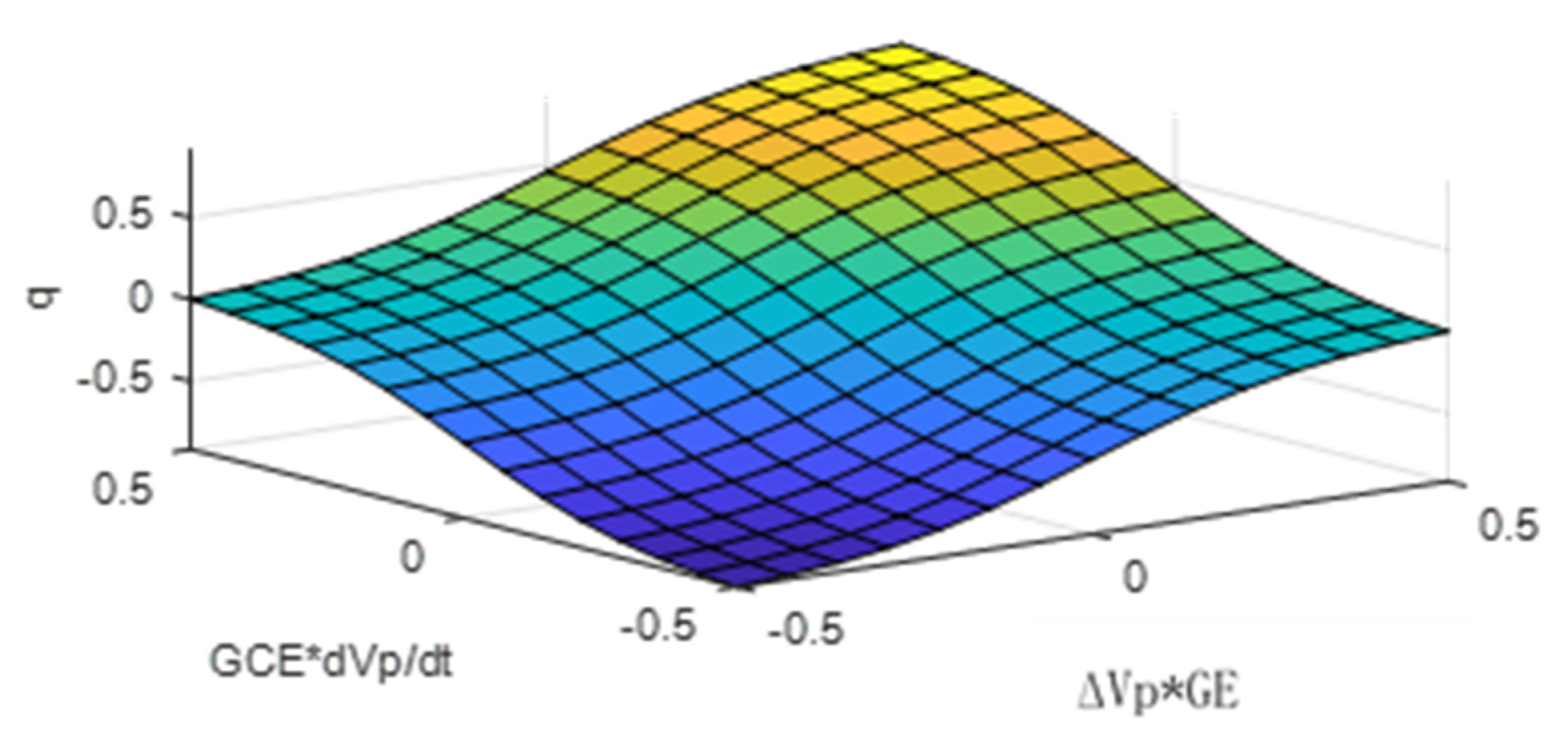
Design of a secondary voltage fuzzy logic PID control system, and then applied to the real Egyptian grid 500/220 kV model;
iv.
Application of tertiary voltage control in the Egyptian grid to achieve the maximum reactive power reserve in different operation conditions.
The remainder of this paper is structured as follows. Section 2 presents a description of the modeling and simulation of the power grid of Egypt. Section 3 presents a procedure to select the pilot buses and the application of SecVC. The idea of the WAMS and its configuration are presented in Section 4. The TerVC system is described in Section 5. The simulation results are presented in Section 6. A general discussion is presented in Section 7. Finally, Section 8 summarizes the main conclusions.

2. Egyptian Power Grid

A model and simulation of the Egyptian grid were fully described in [25]. The model represented the peak demand in 2016. Here, the model was updated to include the five new power stations and their associated new transmission facilities, which have already been in service. The new power plants include the world’s three largest combined cycle power stations with installed capacities of 4.8 GW each (8 × 400 MW GT + 4 × 400 MW ST). They are located in Burullus, Beni Suef, and New Capital, in addition to the world’s largest photovoltaic park in Benban with 1.8 GW, which was constructed near Aswan, and the expanded Gabalzeet wind farms of 540 MW. Due to the introduction of the above large power plants and their associated expanded transmission network, the system was partitioned geographically into six zones instead of the five zones that the early 2016 system was divided into, as described in [25]. The six regions are the Cairo region, the Alexandria region, the Canal region, the Delta region, the Middle Egypt region, and the Upper Egypt region. A geo-schematic diagram of the upgraded power grid of Egypt is shown in Figure 1 [26].
The code of operation of the Egyptian grid is designed such that the grid can operate without any violations in voltage and frequency in case of a single circuit outage in the 500 kV voltage level transmission system (N-1 contingency) or a double circuit outage in the 220 kV voltage level transmission system (N-2 contingency). In Section 4, the WAMS configuration is optimally designed to comply with the code of operation of the grid.

3. Secondary Voltage Control and Pilot Bus Selection

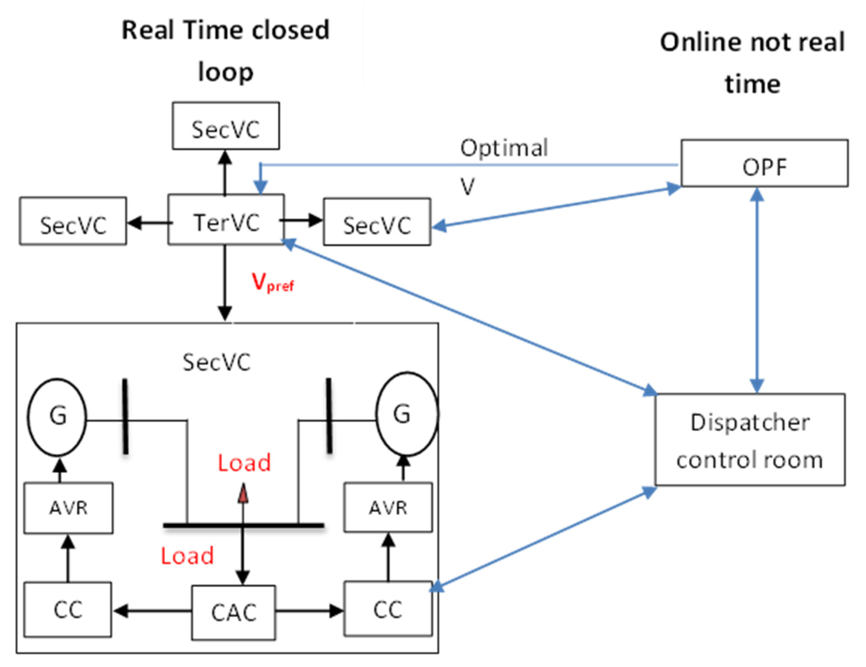
3.1. Secondary Voltage Control Concept

SecVC is applied to achieve acceptable values of voltages at the load buses in a region and keep the voltage at acceptable values even in cases of large disturbance such as line, generator, or transformer outage. As the voltage control of each load bus is not mandatory, a load bus, which is the most sensitive to changes in reactive power, is selected to perform the secondary voltage control in each control region.
To design the SecVC, a linearized model was obtained, as illustrated in Equations (1)–(3), neglecting small changes in the voltage due to changes in the active power [6].
[ S G G S G L S L G S L L ] [ Δ V G Δ V L ] = [ Δ Q G Δ Q L ]
Δ V L = [ A ]   Δ Q L + [ B ]   Δ V G
Δ V P = [ M ] Δ V L
where
Δ V G = change of voltages of PV buses;
Δ V L = change of voltages of PQ buses;
Δ Q G = change of injected reactive power;
Δ Q L   = change of demand reactive power;
[ S G G ], [ S G L ], [ S L G ] and [ S L L ] are submatrices that relate to changes in the voltage to the change in reactive power;
[ A ] = [ S L L ] 1   and   [ B ] = [ S L L ] 1 [ S L G ] ;
M is a 0-1 matrix to show which of the load buses will be employed as pilot buses. It has a size of (nP × nL), where nP stands for the number of pilot buses, and nL stands for the number of load buses.

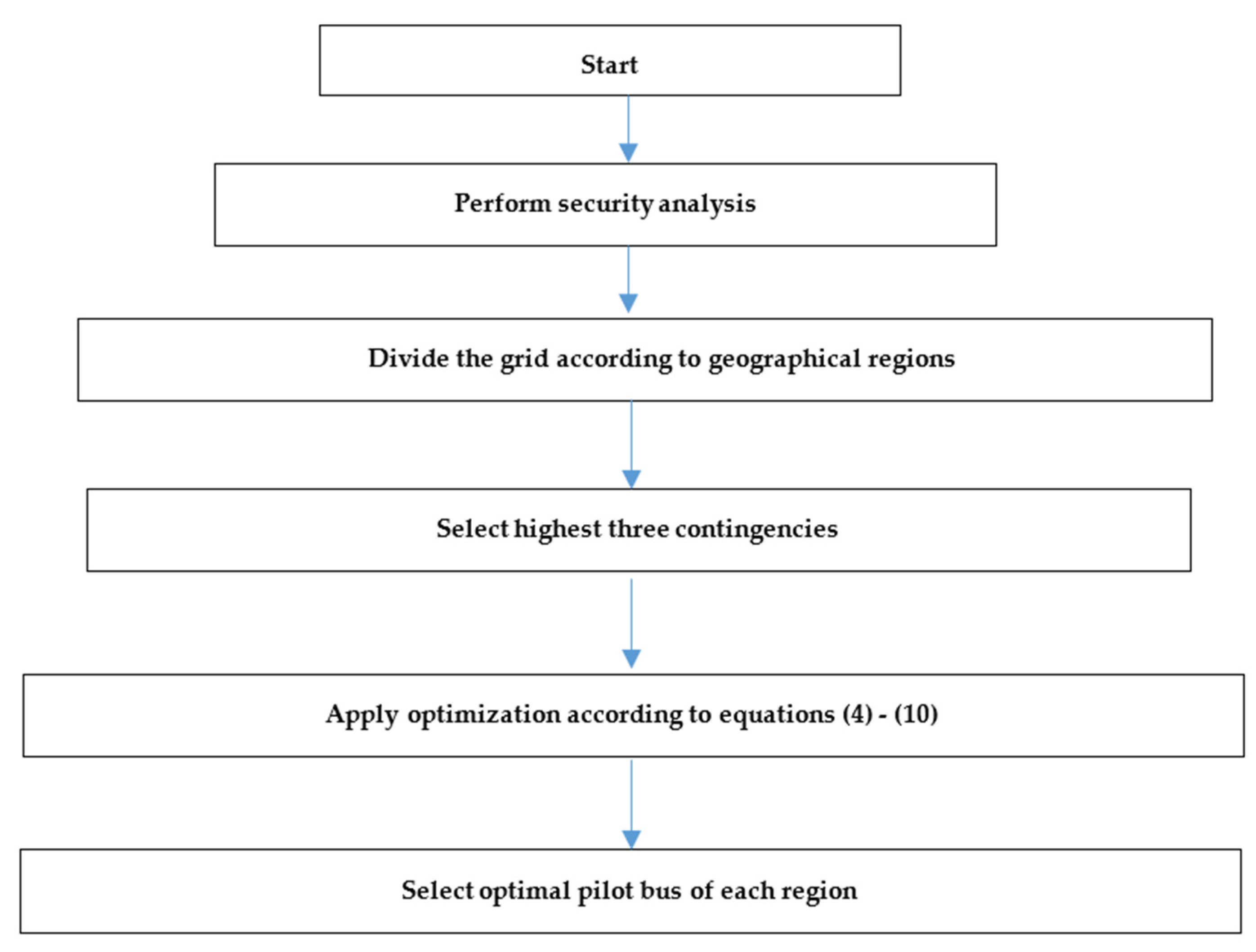
3.2. Pilot Buses Selection

Pilot bus selection is a complex non-linear problem [27,28,29,30]. In this paper, a novel method for selecting pilot buses is proposed based on different grid conditions [31]. In this study, the base case and three outages in the Egyptian power system were considered. The three server outages had the highest effect on the grid operation in terms of the possibility of driving the system to instability. Thus, a set of scenarios was generated. In each of these scenarios, the following optimization process was followed to select the optimal pilot bus of each region.
O = W 1 F 1 + W 2 F 2 + W 3 F 3
W 1 + W 2 + W 3 = 1 ,   W 1 = W 2 = W 3 = 1 3
F 1 = d ϵ d Π d × | | Δ V L | | infinity
d ϵ d Π d = 1
F 2 = d ϵ d Π d × ( i ϵ p OI i ) ,   OI i = Δ V i Δ V L
F 3 = d ϵ d Π d × ( i ϵ p CIn i ) ,   CIn i = q Δ V i
F = λ 1 O Base   case + λ 2 O Contingency   1 + λ 3 O Contingency   2 + λ 4 O Contingency   3
λ 1 + λ 2 + λ 3 + λ 4 = 1 ,   λ 1 = λ 2 = λ 3 = λ 4 = 0.25
where O is the multi-objective function to select the optimal pilot bus of each region in a certain operation condition (base case or contingency). F 1 is an objective function for the minimization of load bus deviation in a certain region. Π d is the probability associated with scenario d , while d is the set of all the scenarios (candidate pilot bus). F 2 is an objective function for the maximization of observability of the candidate pilot bus and its representation to the rest of the load buses. The observability degree is calculated according to the observability index OI , which is calculated based on the voltage coupling ratio between buses. F 3 is an objective function for the maximization of the controllability of the candidate pilot bus according to the controllability index ( CIn ), which represents the sensitivity of the generator control actions to the load bus voltage magnitude. W 1 ,   W 2 ,   and   W 3 are the weighting factors of each of the three objective functions at a certain operating condition. F is the objective function to select the optimal pilot bus of each region considering different operating conditions. λ 1   ,   λ 2 ,   λ 3 ,   and   λ 4 are the weighting factors of each operating condition. The four operating conditions were assumed to have the same weight. The contingencies were selected according to the contingency analysis. Figure 2 shows a flow chart of the optimization process to select the optimal pilot bus of each region.

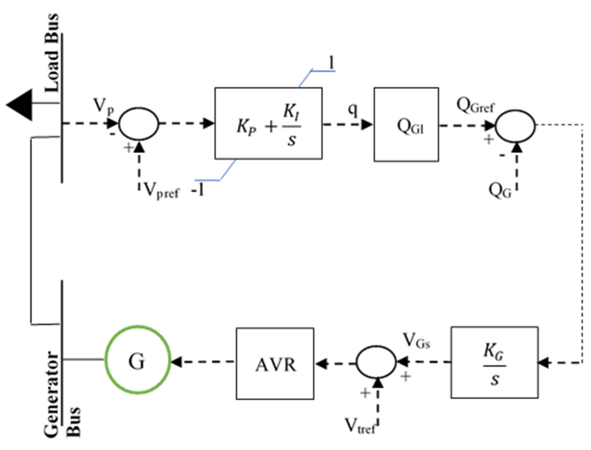
3.3. Secondary Voltage Control Strategy

The objective of the SecVC strategy in this study was to achieve the optimal values of the voltages at the load busbars in order to maximize the reactive power reserve. The process was carried out by the measurements obtained from the PMUs, coordinated PID control, and reactive power integral control. The controlled power stations generate or absorb reactive power to maintain the voltage at the pilot buses according to (12) [11,27]:
Δ V P = MA Δ Q L + M B Δ V G
In previous research [2,21], the SecVC strategy has been applied, as shown in Figure 3 and Figure 4. In this study, the control was implemented in DIgSILENT software using the built-in functions, and the output of SecVC was an additional signal to the AVR set-point. The following equations describe the control strategy:
Central Area Control (CAC) equations:
V p r e f V p = Δ V p
q = ( K p + K I s )   Δ V p
Unit Cluster Control (CC) equations:
Q r e f = q Q G l
V G S = K G s ( Q r e f Q G )
where
V p r e f = pilot bus set-point voltage calculated from the TerVC level;
V p   = pilot bus current voltage;
Δ V p   = voltage error;
q = control signal (action);
Q G l = reactive power capability curve limits of the generator or power station;
V G S = additional signal to the AVR set-point;
The regulator integral gain K G equals X T G + X e q T G [21].
The minimization results that enable the calculations of the PI controller parameters are shown in (17) and (18). The time constant was set as 50 s.
K p = 1 X T G Q G L
K I = 1 + K p Q G l X e q T c Q G l X e q
In [2,7], a neural network was developed to perform the secondary voltage control process. The secondary voltage control system consists of a PID controller tuned by a neural network-based genetic algorithm in the CAC, in addition to CC elements. The system performance was found to be better than using classical control techniques. In this study, the secondary voltage, a PI/PID controller in the CAC, was replaced by a Fuzzy Logic PID (FLPID) controller. The FLPID controller was established as two parallel controllers—a PI controller and a PD controller. The inputs of the controller were the error in the pilot bus voltage, as illustrated in (14), and the change in the pilot bus voltage, which was chosen instead of the change in the error Δ V p . This avoided the harmful effects of step changes in the pilot bus reference signal V p r e f on sharply triggering the derivative action. The FLPID controller is illustrated in Figure 5. The parameters GE, GCE, GU, and GCU were calculated based on an arbitrary PID controller in a certain case, as illustrated in (19)–(21). The fuzzy inference system is shown in Figure 6. The FLPID controller was designed using MATLAB software and integrated with the DIgSILENT model of the system [24].
K P = G C U × G C E + G U × G E  
K I = G C U × G E
K D = G U × G C E

4. Wide Area Measurement System (WAMS)

With the increasing variability in power systems due to the integration of large amounts of renewable energy, WAMS are highly required to replace SCADA systems [31,32,33,34,35,36]. WAMS in the SecVC process will play an important role in the measurement of the voltages of pilot buses and will also help in selecting the best generator to be employed as a reactive power supporter. In this study, the following procedure was applied to the Egyptian power grid model:
i.
The optimal PMU placement was carried out in the modeled grid;
ii.
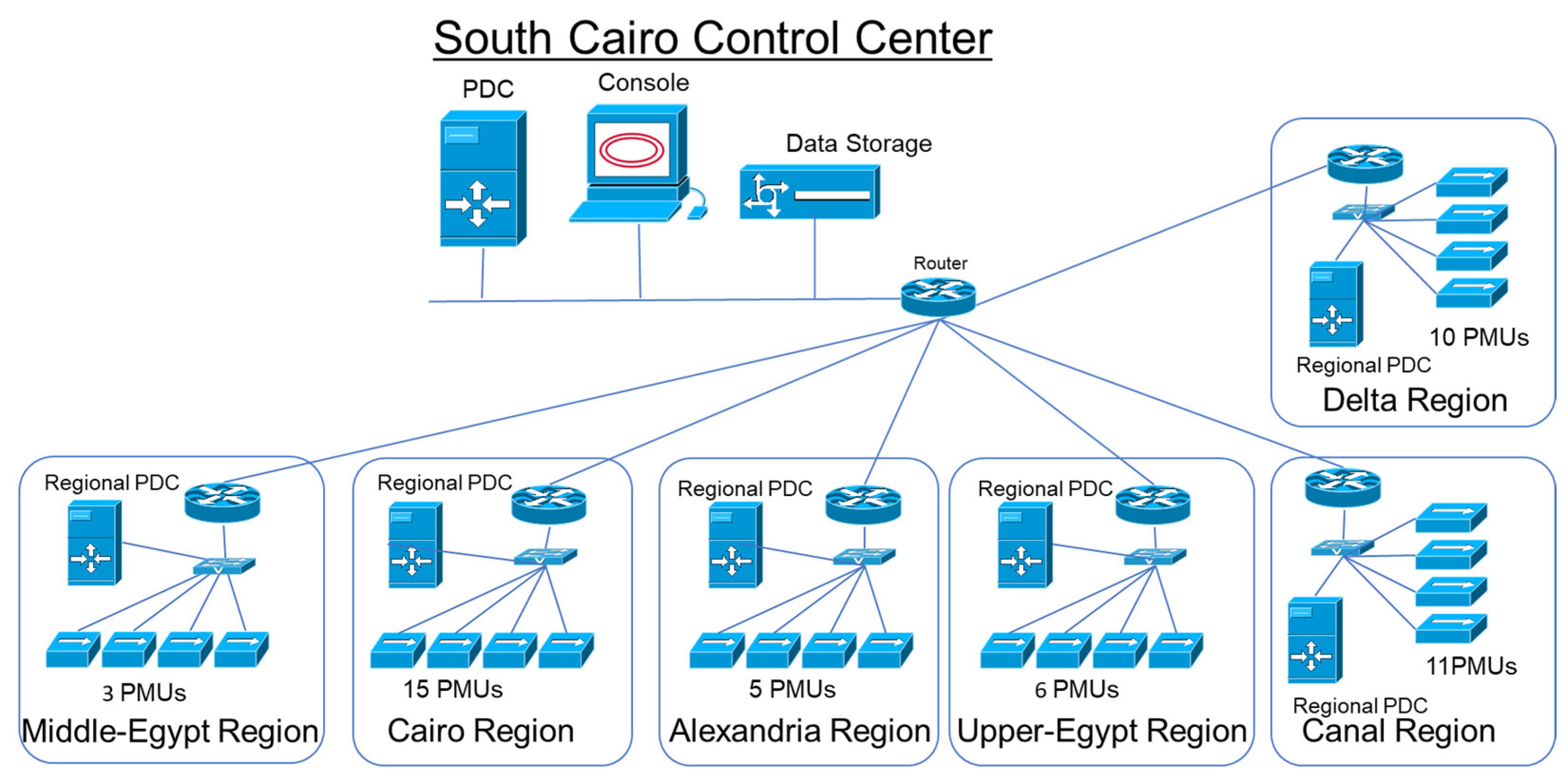
A complete optimal WAMS configuration was designed for the grid in a normal case, including national and regional PDCs;
iii.
A complete optimal WAMS configuration was designed for the grid to achieve (N-1)/(N-2) contingency (outage of PMU, transmission line, cable, or transformer) according to the Egyptian power grid code.
Figure 7 shows the optimal WAMS configuration of the Egyptian power grid, including all the required elements: PMUs, PDCs, communication links, operator, and data storage.
Figure 8 shows a flow chart for the optimal configuration of a WAMS in the Egyptian grid considering the six regions mentioned in Section 2.

4.1. Optimization for PMU Placement

Adding a PMU in each busbar of the grid is the best solution for accurate and reliable measurement, but it is costly and unnecessary [2]. The following is an optimization process to minimize the number of PMUs in the grid such that all busbars could be observed. The fact is that the PMU can measure the busbar voltage where it is installed and the voltage of any busbar connected to it through only one transmission line, cable, or transformer.
Objective :   m i n i = 1 n C i x i
Variables: Busbars where the PMUs are installed.
Constraints: In the base case, the voltage at each busbar is measured by one PMU, at least, i.e., K = 1. Additionally, in the (N-1) contingency case, two PMUs are employed, i.e., K = 2.
In the power grid of Egypt studied here, the 220 kV transmission lines comply with the (N-2) security criterion and the 500 kV lines comply with the (N-1) criterion. Most of the 220 kV lines in Egypt are double circuits, so considering the (N-1) contingency for the PMUs is equivalent to considering (N-2) for the double-circuit transmission lines in the 220 kV network. This can be achieved as per Equation (23) when K = 2. Therefore, the following constraint was considered:
f ( X ) K  
In Equation (23), f ( X ) implies that at least K PMUs can measure the voltage at each busbar in the power system. K is a vector whose entries are all the same value.

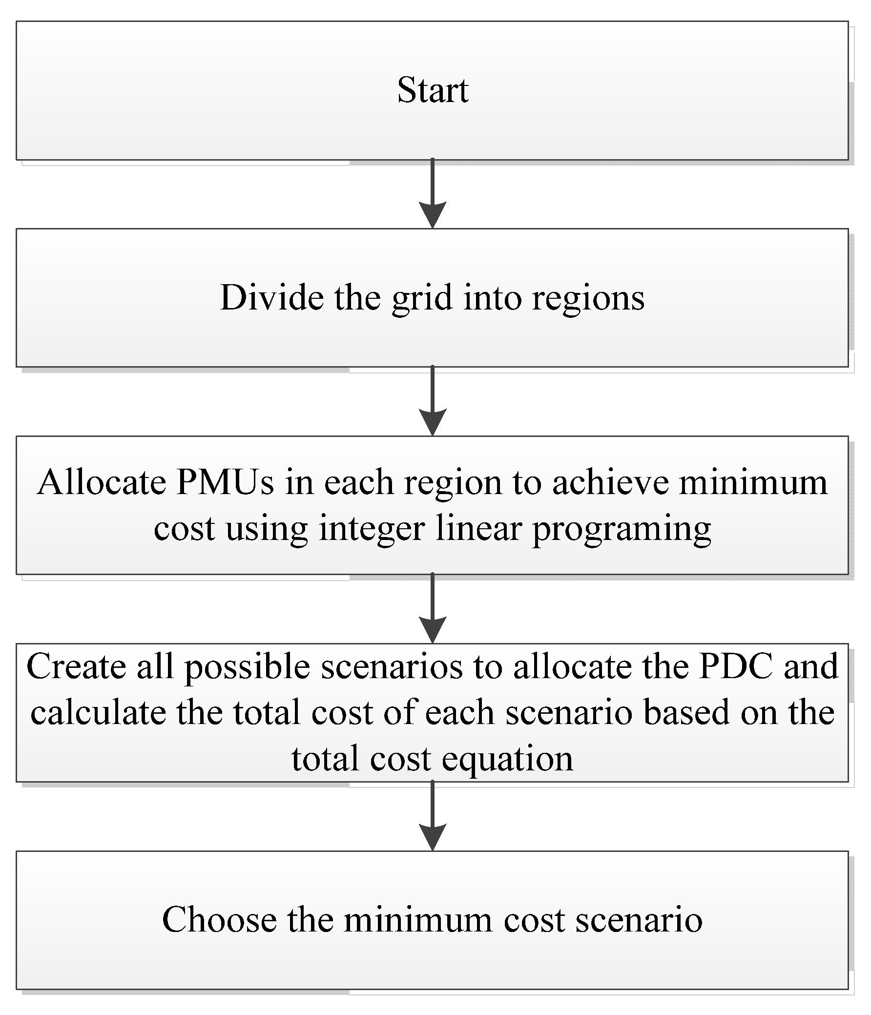
4.2. Optimization for PDC Placement

The idea of the optimization of PDC placement is to minimize the total cost of the WAMS, including switches, routers, and communication links, such that the WAMS configuration is applied to the power grid with minimal cost by using (24) as an objective function and considering (23) as a constraint.
m i n { i = 1 n ( C i X i ) + C f b i = 1 m ( l i ) + C S w C I }
where
C f b = installation cost of one kilometer of optical fiber link;
l i = total length of the optical fiber link connecting the ith PMU and PDC;
m   = number of PMUs;
C S w = cost of the installation of one switch;
C I   = system buses in the communication path between the PMU and PDC.
Upon allocating the PMUs, we allocated a PDC at each busbar and then calculated the cost of the communication system. The lowest cost led to the optimal location of the PDC in each region.

5. Tertiary Voltage Control (TerVC)

Generally speaking, the TerVC strategy is considered here as an optimal power flow process to operate the power grid while achieving certain objectives such as minimal power losses, minimal generation cost, and maximum reactive power reserve.
To improve the voltage stability of the power system, two approaches can be used. The first is to maximize the reactive power reserve, and the second is to maintain the required stability margin in the current operating conditions. During a contingency or load change, the active power of the line loadings will not change significantly [7], unlike the reactive power flow, which can highly change. Sufficient reactive power reserves are required to be available to cover the reactive power changes caused by a contingency or a change in load. Simply speaking, the reactive power reserve [35,36] is the ability of the generators to support bus voltages under load change conditions or contingency. The reactive power reserve is calculated using Equation (25), while the objective function that maximizes the reactive power reserve is calculated using Equation (26).
Q g r e s = Q g m a x Q g
OF = max i   W g i ( Q g i m a x Q g i )
where
Q g r e s = reactive power reserve;
Q g m a x = maximum reactive power of the generator as per the capability curve;
Q g = actual generator reactive power;
i = number of generators assigned to support the pilot bus in a certain region;
W g i = participation factor of the generator providing reactive power support.
Based on [36], the W g i formula is illustrated in (27) which is calculated with reference to the minimum eigenvalues of reduced power flow Jacobians.
W g i = Δ Q g i / ( max Δ Q g )
Δ Q g i is the change in the reactive power of generator i to support the pilot bus. The maximization of the reactive power reserve is used here as the objective function of the tertiary voltage control in contingencies and load variation events while minimizing the total power losses is the objective in normal operating conditions. The aim of this strategy is to ensure the availability of sufficient reactive power for any upcoming power system disturbance event while maintaining the equality and non-equality constraints of the grid.

6. Optimization and Simulation Results

6.1. Optimal WAMS Configuration Results

Table 1 summarizes the results of carrying out the optimization process in MATLAB to optimally configure the WAMS in the Egyptian grid considering the cost of a PMU is USD 40,000 and the cost of 1 km of optical fiber is USD 4000.

6.2. Results of Pilot Bus Selection

As illustrated in Section 3, the idea of optimally selecting the pilot busbar is to minimize the load voltage deviation and maximize the controllability and observability in different operating conditions. The chosen conditions were the base case and three (N-2) contingencies that have the highest ranking. Contingency analyses were performed, and the results are shown in Table 2. The optimal selection of the pilot bus was then based on considering the normal condition and the highest three contingencies according to Equations (4)(10).
The optimal results were found in different operating conditions according to both the normal and contingency operating conditions. The results were compared to state-of-the-art techniques and show better performance in terms of the voltage deviation index in different operating conditions.

6.3. TerVC and SecVC Results

The TerVC and SecVC systems were applied to the simulated Egyptian grid. The coordinated FLPID controller parameters were calculated using the equations to automatically track the optimal pilot bus voltage.
The power system optimization was performed to achieve the maximum reactive power reserve in the case of a certain disturbance to determine the optimal pilot bus voltage in reference to the SecVC during the disturbance.

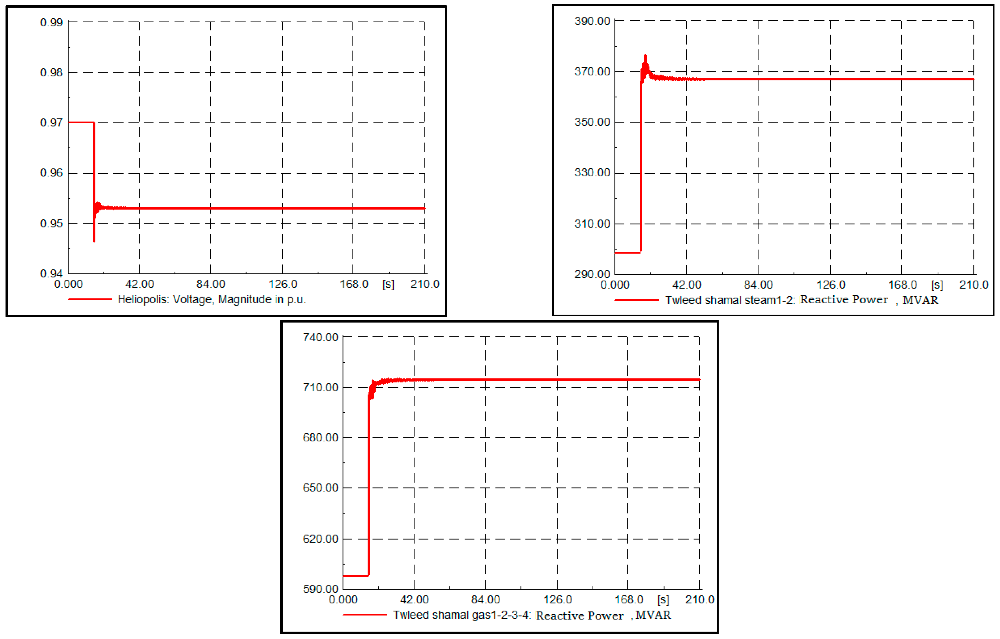
6.3.1. Case 1: Line Outage

Assuming a line outage event occurred in the 220 kV line connecting the NH and South Qena busses (a two-circuit outage), the South Qena load bus voltage, which is the pilot bus of the Upper Egypt region, was reduced to 0.79 pu without applying the SecVC.
This value does not comply with the Egyptian Grid Code [37]. Based on the TerVC results, the pilot bus voltage magnitude after this disturbance should be 0.947 pu to achieve the maximum reactive power reserve, which the SecVC will enact to accomplish this value, as shown in Figure 9. This means that the High Dam (HD) hydraulic power plant and the Aswan Dam hydraulic power plant should inject reactive power. Despite the injection of the reactive power that supports the bus voltages, the reactive power reserve after applying the SecVC was 72% for the HD power plant and 65% for the Aswan Dam power plant. The FLPID controller acted to track the optimal South Qena bus (Upper Egypt region pilot bus) voltage. The control was applied to the South Qena bus, as it was effectively varied due to the disturbance, while the other pilot buses only slightly changed or did not change; the maximum change in the other pilot buses was 0.0004 pu.

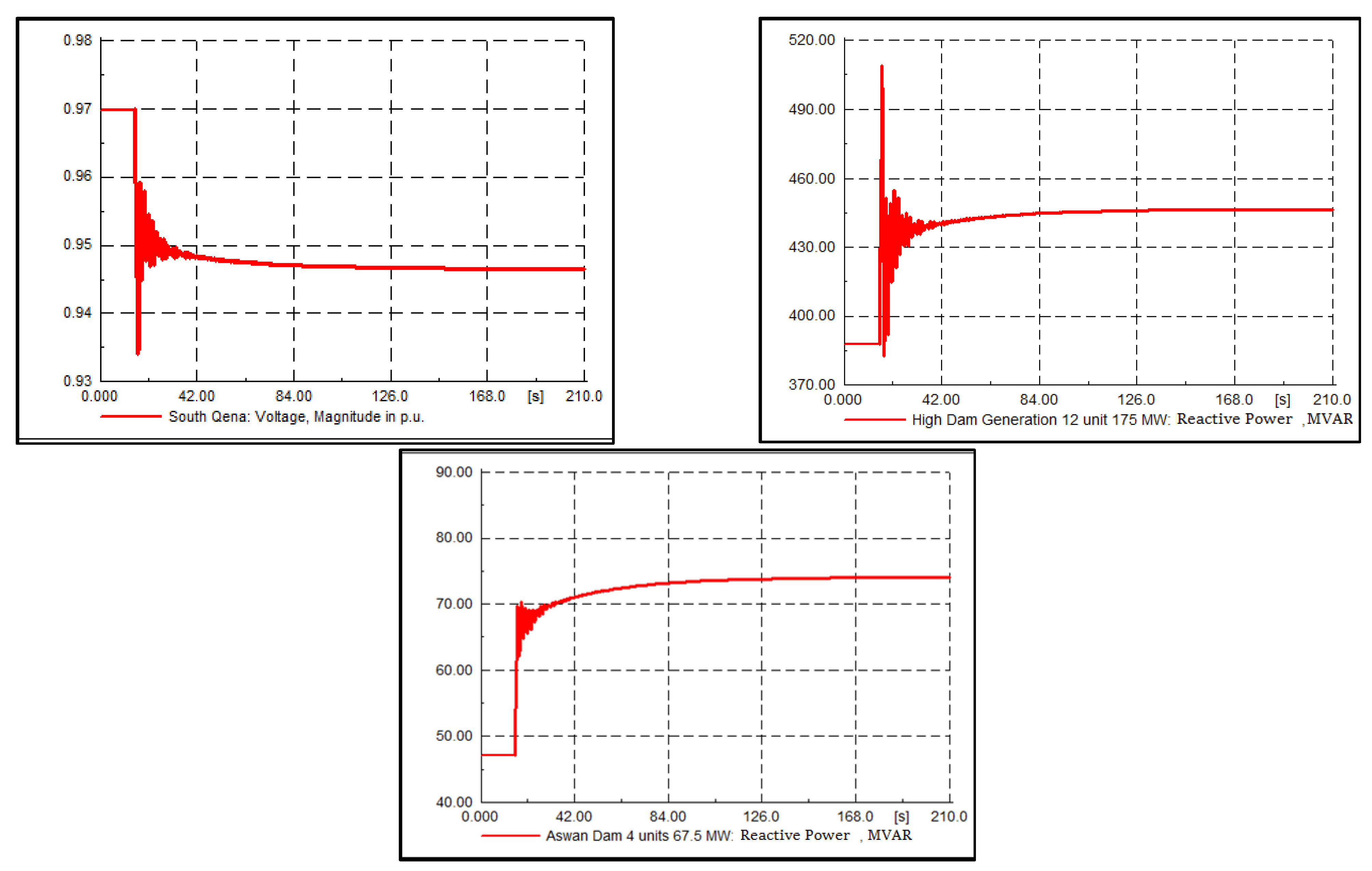
6.3.2. Case 2: Generation Outage

Assuming that the Beni Suef combined-cycle power station was operating at 75% of its rated capacity (i.e., producing 3600 MW), with one block out of service and three blocks working at maximum capacity, each block produced 1200 MW of active power and 622 MVAR of reactive power. Each generator produced 400 MA and 207.33 MVAR. The test in Case 2 was an outage of a single block (1200 MW) of the three operating blocks. The simulation of this test resulted in decreased voltage at the Beni Suef 220 kV load bus to 0.94 pu without applying the SecVC. When the TerVC was implemented to achieve the maximum reactive power reserve in this case, we found that the optimal voltage should be 0.979 pu, which was achieved using SecVC, as shown in Figure 10. In order to reach the optimal value, reactive power support was required from the rest of the Beni Suef power station units and the Kurymat power station units. The FLPID controller tracked the optimal pilot bus voltage. The remaining reactive power reserve at the Beni Suef power station was 5% and the reactive power reserve at the Kurymat power station was 38.6%.
TerVC was carried out in the Middle Egypt region because the other pilot buses had much fewer changes compared to the pilot bus at Beni Suef. The maximum change in the other pilot buses was 0.0005 pu. When the tertiary voltage control objective was to minimize the total power loss during this contingency, the reactive power reserve was 0% for the Beni Suef power station, which means no reactive power support could take place if any other event occurred after the generation outage.

6.3.3. Case 3: Load Increase Disturbance Test in Cairo Region

Assuming that a load increase of 25% took place at the Heliopolis busbar (Cairo region pilot bus), Figure 11 shows the system response with the SecVC strategy. The reactive power of the supportive generating units at the Tawleed Shamal station injected more reactive power. The FLPID controller tracked the optimal voltage magnitude of the Heliopolis busbar, which was 0.952 pu as calculated using the OPF at the TerVC level. SecVC was applied in the Cairo region as it was significantly affected due to this load disturbance, unlike the other regions, which were slightly affected. The maximum change in the other pilot buses was 0.000008 pu.

6.4. Voltage Deviation Index

Table 3 shows a comparison of the system performance in terms of the voltage deviation index (Xrms) [38], as illustrated in Equation (28).
X r m s = 1 n L i = 1 n L ( V i n V i ) 2
where n L is the number of load buses in the power system, which equaled 81 buses in this case study. V i n is the nominal voltage of the load bus and V i is the actual load bus voltage.
Three SecVC methods were considered: (i) the proposed SecVC method, (ii) the SecVC method of [11], and (iii) the SecVC method of [12]. These were in addition to the system without SecVC. Note that in the methods of [11] and [12], the pilot bus selection was based on optimization techniques. The results show that the system with the proposed SecVC method achieved the best performance in terms of a lower voltage deviation index, compared to the other methods, by controlling the reactive power.

7. Discussion

This study illustrates a method to apply secondary voltage control to the Egyptian grid considering levels of 500/220 kV. To apply SecVC, a set-point is needed for each pilot bus voltage, which was optimally selected as the most controllable and observable load bus in each region.
The set-point of the pilot bus voltage was calculated based on an optimal power flow process to achieve a maximum reactive power reserve. Three case studies were carried out in different regions to simulate different events, namely generator contingency, line contingency, and load increase. The results show that the remaining reactive power reserve using SecVC at the Beni Suef power station was 5% and the reactive power reserve at the Kurymat power station was 38.6% when the generator contingency occurred in the Middle Egypt region. When the same contingency was simulated, but with the optimal power flow applied to achieve minimal power losses instead of achieving the maximum reactive power reserve, the results show that the reserve reactive power at the Beni Suef power station was 0%. This will not allow for any reactive power support if further contingency events occur. Additionally, when the line outage event occurred in the Upper Egypt region, reactive power levels of 72% at the HD and 65% at the Aswan Dam were still present as reserves after applying the proposed SecVC strategy.
To implement regional SecVC, a WAMS is required to measure the voltages of system buses. In addition, to avoid sending the wrong data between regions, an optimal WAMS configuration was applied considering the regions and the regional control centers in the power grid. The proposed method for the WAMS configuration was applied to achieve (N), (N-1), and (N-2) conditions. The results were compared with those of [14]. The comparison proved that the proposed method avoided the possibility of sending PMU data to the wrong regional control center, unlike the method in [14], which may lead to sending at least 3–5 wrong data from the PMUs to the regional control centers.
For the implementation of a WAMS in a practical power system, updated costs of all components and their installation should be used in estimating the total cost. In addition, the costs of other necessary works should be included [34,39,40]. The optimal number and locations of PMUs should be considered.
The proposed method for selecting the pilot bus in each region was compared to the methods in [11,12] in terms of the voltage deviation index in three different operating conditions. The results show that the proposed method achieved less voltage deviation than that of [11] by 55% on average in the three cases of power system scenarios and 42% less deviation on average than that of [12].

8. Conclusions

The proposed secondary coordinated fuzzy logic PID controller reached the optimal voltage profile under different operating conditions. A method for pilot bus selection was presented, and its proficiency was shown based on various operating conditions, topologies, and real geographical regions. The proposed method was more effective in comparison to other techniques. The maximization of the reactive power reserve ensured better voltage stability in terms of enough reactive power reserve at the generating units for load bus voltage support during contingencies. The proposed method of the WAMS configuration was applied to the power grid of Egypt to provide a clear techno-economic analysis of the system under different scenarios.
The proposed WAMS configuration was shown to be efficient in covering the whole grid, considering the real regional zones. The proposed methodology for the optimal configuration of WAMS realized the (N-2) security criterion for the 220 kV system and the (N-1) criterion for the 500kV system. The cost of the WAMS configuration, which considers the contingency case, was found to be 63% higher than the cost of the base case (N) conditions for the studied system. This was calculated by dividing the difference between the two costs by the base case cost.
The results show that the power system with the proposed SecVC provided an improved voltage profile in terms of a better voltage deviation index compared to other state-of-the-art voltage control techniques.

Author Contributions

Conceptualization, O.H.A. and H.H.F.; methodology, O.H.A. and H.H.F.; software, O.H.A. and H.H.F.; validation, O.H.A. and H.H.F.; formal analysis, O.H.A. and H.H.F.; investigation, O.H.A. and H.H.F.; resources, O.H.A. and H.H.F.; data curation, O.H.A. and H.H.F.; writing—original draft preparation, O.H.A. and H.H.F.; writing—review and editing, O.H.A. and H.H.F.; visualization, O.H.A. and H.H.F.; supervision, O.H.A. and H.H.F.; project administration, O.H.A. and H.H.F.; funding acquisition, O.H.A. and H.H.F. All authors have read and agreed to the published version of the manuscript.

Funding

This research received no external funding.

Institutional Review Board Statement

Not applicable.

Informed Consent Statement

Not applicable.

Data Availability Statement

Not applicable.

Conflicts of Interest

The authors declare no conflict of interest.

References

  1. Fayek, H.H.; Abdalla, O.H. Operation of the Egyptian Power Grid with Maximum Penetration Level of Renewable Energies Using Corona Virus Optimization Algorithm. Smart Cities 2022, 5, 34–53. [Google Scholar] [CrossRef]
  2. Abdalla, O.H.; Fayek, H.H.; Ghany, A.M.A. Secondary Voltage Control Application in a Smart Grid with 100% Renewables. Inventions 2020, 5, 37. [Google Scholar] [CrossRef]
  3. Simpson-Porco, J.W.; Dörfler, F.; Bullo, F. Voltage collapse in complex power grids. Nat. Commun. 2016, 7, 10790. [Google Scholar] [CrossRef]
  4. Guo, Q.; Sun, H.; Zhang, M.; Tong, J.; Zhang, B.; Wang, B. Optimal voltage control of PJM smart transmission grid: Study, implementation, and evaluation. IEEE Trans. Smart Grid 2013, 4, 1665–1674. [Google Scholar] [CrossRef]
  5. Morattab, A.; Akhrif, O.; Saad, M. Decentralized Coordinated Secondary Voltage Control of Multi-Area Power Grids Using Model Predictive Control. Proc. IET Gener. Transm. Distrib. 2017, 11, 4546–4555. [Google Scholar] [CrossRef]
  6. Lagonotte, P.; Sabonnadiere, J.C.; Léost, J.Y.; Paul, J.P. Structural Analysis of the Electrical System: Application to the Secondary Voltage Control in France. IEEE Trans. Power Syst. 1989, 4, 479–484. [Google Scholar] [CrossRef]
  7. Abdalla, O.H.; Fayek, H.H.; Ghany, A.G.M.A. Secondary and Tertiary Voltage Control of a Multi-Region Power System. Electricity 2020, 1, 37–59. [Google Scholar] [CrossRef]
  8. Corsi, S.; Chinnici, R.; Lena, R.; Vannelli, G.; Bazzi, U.; Cima, E. General application to the main Enel’s power plants of an advanced voltage and reactive power regulator for HV network support. In Proceedings of the CIGRE Conference, Struga, North Macedonia, 23–25 September 1998. [Google Scholar]
  9. Su, H.-Y.; Liu, T.-Y. Enhanced Worst-Case Design for Robust Secondary Voltage Control Using Maximum Likelihood Approach. IEEE Trans. Power Syst. 2018, 33, 7324–7326. [Google Scholar] [CrossRef]
  10. Su, H.-Y.; Kang, F.-M.; Liu, C.-W. Transmission Grid Secondary Voltage Control Method Using PMU Data. IEEE Trans. Smart Grid 2018, 9, 2908–2917. [Google Scholar] [CrossRef]
  11. Daher, N.A.; Mougharbel, I.; Saad, M.; Kanaan, H.Y.; Asber, D. Pilot Buses Selection Based on Reduced Jacobian Matrix. In Proceedings of the 2015 IEEE International Conference on Smart Energy Grid Engineering (SEGE), Oshawa, ON, Canada, 17–19 August 2015; pp. 1–7. [Google Scholar] [CrossRef]
  12. Su, H.-Y.; Hong, H.-H. A Stochastic Multi-Objective Approach to Pilot Bus Selection for Secondary Voltage Regulation. IEEE Trans. Power Syst. 2020, 35, 3262–3265. [Google Scholar] [CrossRef]
  13. Mohammadi, M.B.; Hooshmand, R.-A.; Fesharaki, F.H. A new approach for optimal placement of PMUs and their required communication infrastructure in order to minimize the cost of the WAMS. IEEE Trans. Smart Grid 2016, 7, 84–93. [Google Scholar] [CrossRef]
  14. Pierrou, G.; Wang, X. An Online Network Model-Free Wide-Area Voltage Control Method Using PMUs. IEEE Trans. Power Syst. 2021, 36, 4672–4682. [Google Scholar] [CrossRef]
  15. Jeong, B.-C.; Kwon, D.-H.; Park, J.-Y.; Kim, Y.-J.; Gomis-Bellmunt, O. Optimal Secondary Control to Suppress Voltage Fluctuations in an HVDC-Linked Wind Farm Grid. IEEE Trans. Power Syst. 2022, 37, 2563–2577. [Google Scholar] [CrossRef]
  16. Martinez, D.A.; Mojica-Nava, E.; Al-Sumaiti, A.S.; Rivera, S. A Distortion-Based Potential Game for Secondary Voltage Control in Micro-Grids. IEEE Access 2020, 8, 110611–110622. [Google Scholar] [CrossRef]
  17. Ma, Z.; Wang, Z.; Guo, Y.; Yuan, Y.; Chen, H. Nonlinear Multiple Models Adaptive Secondary Voltage Control of Microgrids. IEEE Trans. Smart Grid 2021, 12, 227–238. [Google Scholar] [CrossRef]
  18. Ge, P.; Zhu, Y.; Green, T.C.; Teng, F. Resilient Secondary Voltage Control of Islanded Microgrids: An ESKBF-Based Distributed Fast Terminal Sliding Mode Control Approach. IEEE Trans. Power Syst. 2021, 36, 1059–1070. [Google Scholar] [CrossRef]
  19. Habibi, S.I.; Bidram, A. Unfalsified Switching Adaptive Voltage Control for Islanded Microgrids. IEEE Trans. Power Syst. 2022, 37, 3394–3407. [Google Scholar] [CrossRef]
  20. Xu, Y.; Sun, H.; Gu, W.; Xu, Y.; Li, Z. Optimal Distributed Control for Secondary Frequency and Voltage Regulation in an Islanded Microgrid. IEEE Trans. Ind. Inform. 2019, 15, 225–235. [Google Scholar] [CrossRef]
  21. Abdalla, O.H.; Ghany, A.M.A.; Fayek, H.H. Coordinated PID secondary voltage control of a power system based on genetic algorithm. In Proceedings of the 2016 Eighteenth International Middle East Power Systems Conference (MEPCON), Cairo, Egypt, 27–29 December 2016; pp. 214–219. [Google Scholar]
  22. Yin, L.; Luo, S.; Wang, Y.; Gao, F.; Yu, J. Coordinated Complex-Valued Encoding Dragonfly Algorithm and Artificial Emotional Reinforcement Learning for Coordinated Secondary Voltage Control and Automatic Voltage Regulation in Multi-Generator Power Systems. IEEE Access 2020, 8, 180520–180533. [Google Scholar] [CrossRef]
  23. Khan, I.; Xu, Y.; Kar, S.; Chow, M.-Y.; Bhattacharjee, V. Compressive Sensing and Morphology Singular Entropy-Based Real-Time Secondary Voltage Control of Multiarea Power Systems. IEEE Trans. Ind. Inform. 2019, 15, 3796–3807. [Google Scholar] [CrossRef]
  24. Abdalla, O.H.; Fayek, H.H.; Ghany, A.A. Secondary Voltage Control of a Multi-region Power System. In Proceedings of the 2019 21st International Middle East Power Systems Conference (MEPCON), 17–19 December 2019; pp. 1223–1229. [Google Scholar] [CrossRef]
  25. Abdalla, O.H.; Ghany, A.A.; Fayek, H. Development of a digital model of the Egyptian power grid for steady-state and transient studies. In Proceedings of the 11th International Conference on Electrical Engineering (ICEENG-11) Paper No 83-EPS, Cairo, Egypt, 3–5 April 2018. [Google Scholar] [CrossRef]
  26. Global Energy Institute, National Energy Grid Egypt. Available online: http://www.geni.org/globalenergy/library/national_energy_grid/egypt/egyptiannationalelectricitygrid.shtml (accessed on 3 February 2022).
  27. Conejo, A.; Gbmez, T.; de la Fuente, J.I. Pilot-bus selection for secondary voltage control. Eur. Trans. Electr. Power 1993, 3, 359–366. [Google Scholar] [CrossRef]
  28. Conejo, A.; Aguilar, M.J. Secondary Voltage Control: Nonlinear Selection of Pilot Buses, Design of an Optimal Control Law, and Simulation Results. IEE Proc. Gener. Transm. Distrib. 1998, 145, 77–81. [Google Scholar] [CrossRef]
  29. Cui, W.; Rao, Y.; Li, C.; Liu, Y.; Ren, P.; Gao, Z.; Wang, H. Voltage Control Partitioning of Wind Power Integration System Based on Pilot-Bus Control Space. In Proceedings of the 2019 IEEE PES Innovative Smart Grid Technologies Asia (ISGT Asia), Changdu, China, 21–24 May 2019; pp. 1919–1923. [Google Scholar] [CrossRef]
  30. Yang, Y.; Sun, Y.; Wang, Q.; Liu, F.; Zhu, L. Fast Power Grid Partition for Voltage Control with Balanced-Depth-Based Community Detection Algorithm. IEEE Trans. Power Syst. 2022, 37, 1612–1622. [Google Scholar] [CrossRef]
  31. Fayek, H.H.; Davis, K.R.; Ghany, A.A.; Abdalla, O.H. Configuration of WAMS and Pilot Bus Selection for Secondary Voltage Control in the Egyptian Grid. In Proceedings of the 2018 North American Power Symposium (NAPS), Fargo, North Dakota, 9–11 September 2018; pp. 1–6. [Google Scholar] [CrossRef]
  32. Corsi, S. Voltage Control and Protection in Electrical Power Systems: From System Components to Wide-Area Control; Springer: New York, NY, USA, 2015. [Google Scholar]
  33. Agrawal, V.K.; Ararwal, P.K. Challenges faced and lessons learnt in implementation of first synchrophasors project in the Northern India. In Proceedings of the 3rd International Exhibition & Conference, New Delhi, India, 19–20 April 2011. [Google Scholar]
  34. Al-Hinai, A.; Karami-Horestani, A.; Alhelou, H.H. A multi-objective optimal PMU placement considering fault-location topological observability of lengthy lines: A case study in OMAN grid. Energy Rep. 2023, 9, 1113–1123. [Google Scholar] [CrossRef]
  35. Arya, L.; Singh, P.; Titare, L. Anticipatory reactive power reserve maximization using differential evolution. Int. J. Electr. Power Energy Syst. 2012, 35, 66–73. [Google Scholar] [CrossRef]
  36. Liu, Y.; Xia, W.B.; Zheng, S.; Wang, K.; Wu, P.; Fang, S. A semi-definite programming approach for solving optimal reactive power reserve dispatch. In Proceedings of the 2017 IEEE PES Asia-Pacific Power and Energy Engineering Conference (APPEEC), Bangalore, India, 8–10 November 2017; pp. 1–6. [Google Scholar]
  37. EETC. “Transmission Grid Code”, Egyptian Electricity Transmission Company. Available online: https://www.eetc.net.eg/grid_code.html (accessed on 2 January 2022).
  38. Fayek, H.H.; Abdalla, O.H. Optimal Settings of BTB-VSC in Interconnected Power System Using TFWO. In Proceedings of the 2021 IEEE 30th International Symposium on Industrial Electronics (ISIE), Kyoto, Japan, 20–23 July 2021; pp. 1–6. [Google Scholar] [CrossRef]
  39. Pal, A.; Vullikanti, A.K.S.; Ravi, S.S. A PMU placement scheme considering realistic costs and modern trends in relaying. IEEE Trans. Power Syst. 2016, 32, 552–561. [Google Scholar] [CrossRef]
  40. Arpanahi, M.K.; Alhelou, H.H.; Siano, P. A Novel Multiobjective OPP for Power System Small Signal Stability Assessment Considering WAMS Uncertainties. IEEE Trans. Ind. Inform. 2020, 16, 3039–3050. [Google Scholar] [CrossRef]
Figure 1. Geo-schematic diagram of the upgraded electric power grid of Egypt [1,25]. Red: 500 kV, light green 220 kV.
Sustainability 15 03338 g001
Figure 2. Pilot bus selection flow chart.
Sustainability 15 03338 g002
Figure 3. Tertiary and secondary voltage control concept.
Sustainability 15 03338 g003
Figure 4. Secondary voltage control strategy.
Sustainability 15 03338 g004
Figure 5. Secondary voltage control fuzzy PID controller.
Sustainability 15 03338 g005
Figure 6. Relation between fuzzy inputs and output.
Sustainability 15 03338 g006
Figure 7. WAMS configuration in the Egyptian grid.
Sustainability 15 03338 g007
Figure 8. WAMS optimization flow chart [31].
Sustainability 15 03338 g008
Figure 9. System response in Case 1.
Sustainability 15 03338 g009
Figure 10. System response in Case 2.
Sustainability 15 03338 g010
Figure 11. System response in Case 3.
Sustainability 15 03338 g011
Table 1. WAMS configuration summary.
MethodConditionNumber of PMUsLocation of
PDC
Number of SwitchesTotal Cost (USD)Number of PMUs not Sending Data to the Right Regional Center
Proposed
method
Base case51South 2209815.7 million0
(N-1) case103Nubaria 50016025.7 million0
Method in [14]Base case48South 2209614.9 million3
(N-1) case98Nubaria 50015424.6 million5
Table 2. Highest contingencies based on (N-2) security criterion.
Rank of the ContingencyTransmission Line
1Line connecting High Dam bus and Nagaa Hammady bus
2Line connecting Zaafarana 2 bus and Ras Gharib bus
3Line connecting Ain Sokhna bus and Zaafarana bus
Table 3. Comparison between different techniques in terms of voltage deviation index in different operating conditions.
Voltage Deviation Index (Xrms)Proposed MethodMethod in [11]Method in [12]Without SecVC
Case 10.0230.0560.0480.090
Case 20.0180.0430.0420.074
Case 30.0040.0100.0090.013
Disclaimer/Publisher’s Note: The statements, opinions and data contained in all publications are solely those of the individual author(s) and contributor(s) and not of MDPI and/or the editor(s). MDPI and/or the editor(s) disclaim responsibility for any injury to people or property resulting from any ideas, methods, instructions or products referred to in the content.

