Article

Performances of the Soil–Bentonite Cutoff Wall Composited with Geosynthetic Clay Liners: Large-Scale Model Tests and Numerical Simulations

1
MOE Key Laboratory of Soft Soils and Geoenvironmental Engineering, Department of Civil Engineering and Architecture, Zhejiang University, Hangzhou 310058, China
2
Key Laboratory of Safe Construction and Intelligent Maintenance of Urban Shield Tunnels of Zhejiang Province, Hangzhou City University, Hangzhou 310058, China
3
Tianjin Zhonglian Gelin Science and Technology Development Co., Ltd., Tianjin 300387, China
*
Author to whom correspondence should be addressed.
Sustainability 2023, 15(3), 1886; https://doi.org/10.3390/su15031886
Submission received: 14 December 2022 / Revised: 12 January 2023 / Accepted: 13 January 2023 / Published: 18 January 2023

Abstract

:
The geosynthetic clay liner (GCL) overlap plays a key role in maintaining hydraulic performance of the barrier systems, e.g., the bottom liner and cover systems. However, its influences on the behavior of the vertical barrier have been rarely investigated. This paper aims to address this issue using the large-scale model test and 3-dimensional finite element (FE) modeling. In the model test, the GCL overlap at the width of 500 mm was tested under a constant hydraulic head of 1 m and confining stress ranging from 10 to 150 kPa using a newly developed large-scale apparatus. Compared with the flexible wall permeameter, this apparatus could guarantee full field-scale GCL overlap to be tested. Results showed that the effective hydraulic conductivity of the GCL overlap decreased from 10−8 to 10−9 cm/s as the confining stress increased from 10 to 150 kPa. The addition of supplemental bentonite paste in between the overlap with a water-to-bentonite ratio of 19:1 contributed to reducing the effective hydraulic conductivity by 60% compared with that for a GCL overlap without bentonite paste. The breakthrough time for the soil-bentonite (SB) cutoff wall composited with GCLs was 64% longer in comparison with that for the single SB wall. Additionally, the breakthrough after 50 years is made for the entire depth of the single SB wall while at the depth no more than 0.9 m for the composite wall with bentonite paste at the GCL overlap. With consideration that the depth of the groundwater table is generally greater than 1 m, the GCL–SB composite cutoff wall will exhibit a good performance in containing groundwater contaminants in the field, especially when applying bentonite paste at the GCL overlap.

1. Introduction

Geosynthetic clay liners (GCLs) consist of a layer of bentonite bonded to layers of geosynthetic. They have gained widespread popularity in geoenvironmental engineering applications [1] due to their low permeability and speed of installation. Currently, GCLs have been proven to be an efficient material in the construction of bottom liners and cover systems [2,3]. Previous researchers and participants have identified the critical role of the GCL overlap in maintaining the effective contaminant [4,5] and investigated the effects of contributing factors, namely, confining stress and supplemental bentonite applied at the overlap, on hydraulic performances of the GCL overlap [6]. Granular and powder bentonite ranging from 400 to 600 g/m are two common materials of supplemental bentonite in the application of bottom liners and cover systems [7,8,9,10]. Both materials may be unsuitable for improving the permeation of the cutoff wall considering that they tend to move downward under gravity. Non-uniformity of bentonite distribution will lead to a higher permeability at the upper part of the vertical barrier. Bentonite paste with a varying water-to-bentonite ratio is another choice [6]. However, none of the research has been conducted to evaluate the effect of supplemental bentonite in the form of paste on the performance of the GCL overlap yet.
The permeameter test was normally conducted to determine the hydraulic conductivity of materials for barriers in geoenvironmental engineering [11,12]. However, it was not able to test on the GCL overlapped seam typically at the shortest length of 150 mm [13] in a standard permeameter cylinder of 70 mm diameter, for which edge effects were greater on the smaller specimen [14]. Additionally, the cross-section of the cell was circular, which varied from the rectangular shape of the GCL overlap in the field; the previous study reported that the amount of the overlap played an important role in the permeation of the system [15]. The large-scale laboratory test has been employed as an effective means to study the hydraulic behavior of the GCL overlap [16]. This technique enables testing on full layers of GCLs, reducing the edge effect of the permeameter cell and avoiding the loss of bentonite near edges due to the cut.
A challenge of large-scale laboratory testing on the GCL overlap was to avoid flow leakage through the wall of the container. A bentonite seal was used all around the GCL during its placement [7,17]. However, the flow leakage could not be eliminated.
With regard to finite element (FE) modeling, this means has been adopted to investigate the flow mechanism at the GCL overlap in both bottom liners and cover systems [18]. Different from the bottom liners and cover systems, soil stress of the SB cutoff wall increases along the wall depth [19,20]. It is unknown how the varied stress state affects the hydraulic performance of the GCL–SB composite cutoff wall and further investigations are required.
To address the issues mentioned above, this study aimed to investigate the influences of the GCL overlap with/without supplemental bentonite paste on the hydraulic performance of the GCL–SB composite cutoff wall, using the large-scale model test and 3-dimensional finite element (FE) modeling. Laboratory tests were firstly carried out to determine the basic material properties of the bentonite component and the GCL specimen. A large-scale apparatus was designed to evaluate the hydraulic performance of the full field-scale GCL overlap. The GCL overlap with an interface of/without supplemental bentonite paste was tested. Influences of confining stress acting at the GCL overlap on its hydraulic behavior were evaluated. The GCL overlap was simulated using the existing fracture model to incorporate the preferential flow at interfaces via the FE modeling, using the large-scale model test results as a benchmark. Predictions of the hydraulic performances of the SB cutoff wall connected with GCLs exposed to Pb(II) were further made using the calibrated model. The parametric study was conducted to evaluate influential factors that govern the hydraulic behavior of the barrier.

2. Materials

2.1. Soil Properties

Liao Ning bentonite was employed in this study. Table 1 presents the mineralogical properties of the Liao Ning bentonite. An X-ray powder diffraction (XRD) test was conducted to obtain the mineral compositions of bentonite. This bentonite was mainly composed of montmorillonite (68.2%). Other minerals could be also found as albite (23.4%), calcite (6.3%) and quartz (2.1%). It is noted that the main base cation of Liao Ning bentonite is Na, which is important for its particular influence on the swelling capacity of the bentonite and, thus, the permeability of the GCL. This was one of the reasons why modified Na-bentonite instead of Ca-based bentonite was chosen for making the GCL.
The physical properties of bentonite are presented in Table 2. The specific gravity of the suspension of the bentonite was measured as 2.67 following BSI [21]. The arbitrary test was also conducted to obtain the liquid (wL) and plastic (wP) limits for the bentonite. As this bentonite mainly contained montmorillonite, the crystal structure of which could absorb additional water and ensure sealing properties. These phenomena would generate a large plasticity index of 227%. The particle size analysis was made via the laser particle analyzer (0.1–3000 μm; S3500; Microtrac MRB, York, PA, USA). The analysis showed that the percentage of particles less than 0.075 mm was more than 90%. This was considered the powder type. Swelling tests on the Liao Ning bentonite in low electrolyte water and CaCl2 solution were carried out following MOHURD [22]. It was expected that the bentonite had a large swelling index (25 mL/2 g) in low electrolyte water solutions due to the high Na-montmorillonite content. The swelling index of the bentonite in CaCl2 solution was reduced to 20.5 mL/2 g in salt solutions. The filtration property of the bentonites was evaluated via the API filtration test following AQSIQ and SAC [23]. The filtrate volume (FL) accumulating in a standard time of 30 min for the bentonite was measured as 12.6 mL.
Coarse silica sand, referred to as Fu Jian sand, was also used to provide support at both ends of the GCL overlap while allowing water passage in permeability tests. The mechanical properties are summarized by Zhu et al. [24].

2.2. Hydraulic Conductivity of the GCL

The GCL employed in this study was needle-punched. Nonwoven geotextile layers composed of the carrier and the Liao Ning bentonite formed the core of the GCL. The hydraulic conductivity of the single layer of GCL (kGCL) to water was measured using the flexible wall permeameter. Five samples of 8 mm in thickness and 70 mm in diameter consolidated at the confining stress (p) of 10, 25, 50, 100 and 150 kPa, respectively. Then, they were exposed to a hydraulic gradient of 10 kPa and water flowed from the bottom to the top of the samples. The kGCL was calculated with Darcy’s law. Results showed that the kGCL decreased from 4.06 × 10⁻⁹ to 2.08 × 10⁻¹⁰ cm/s when p increased from 10 to 150 kPa (Figure 1). Similarly, the kGCL depended on the p corresponding to data compiled from Bouazza [25]. It was explained that the decrease in the kGCL was due to the increase of the seepage path in the GCL, which was a result of the reduction in voids of both the bentonite and geotextile under the p. An empirical fitting was obtained. For samples tested in this study, kGCL (cm/s) = 6.25 × 10−9 × 0.95p + 2.89 × 10⁻¹⁰.

3. Large-Scale Model Testing on the GCL Overlap

3.1. Test Program

Two series of permeability tests were conducted for the overlapped GCLs with full-width seams. The first series was a baseline experiment (donated as S0), which was to determine the permeability of the overlapped GCLs with no bentonite at the seam. The next series (S1) was to study the hydraulic behavior of the GCL overlap samples with supplemental bentonite paste at the seam. Bentonite paste rather than dry bentonite powder was adopted because the latter material tended to move downward under gravity, which would lead to a higher permeability at the upper part of the cutoff wall. In both series, p up to 150 kPa and a hydraulic head of 1 m similar to in situ conditions were applied.

3.2. Testing Apparatus

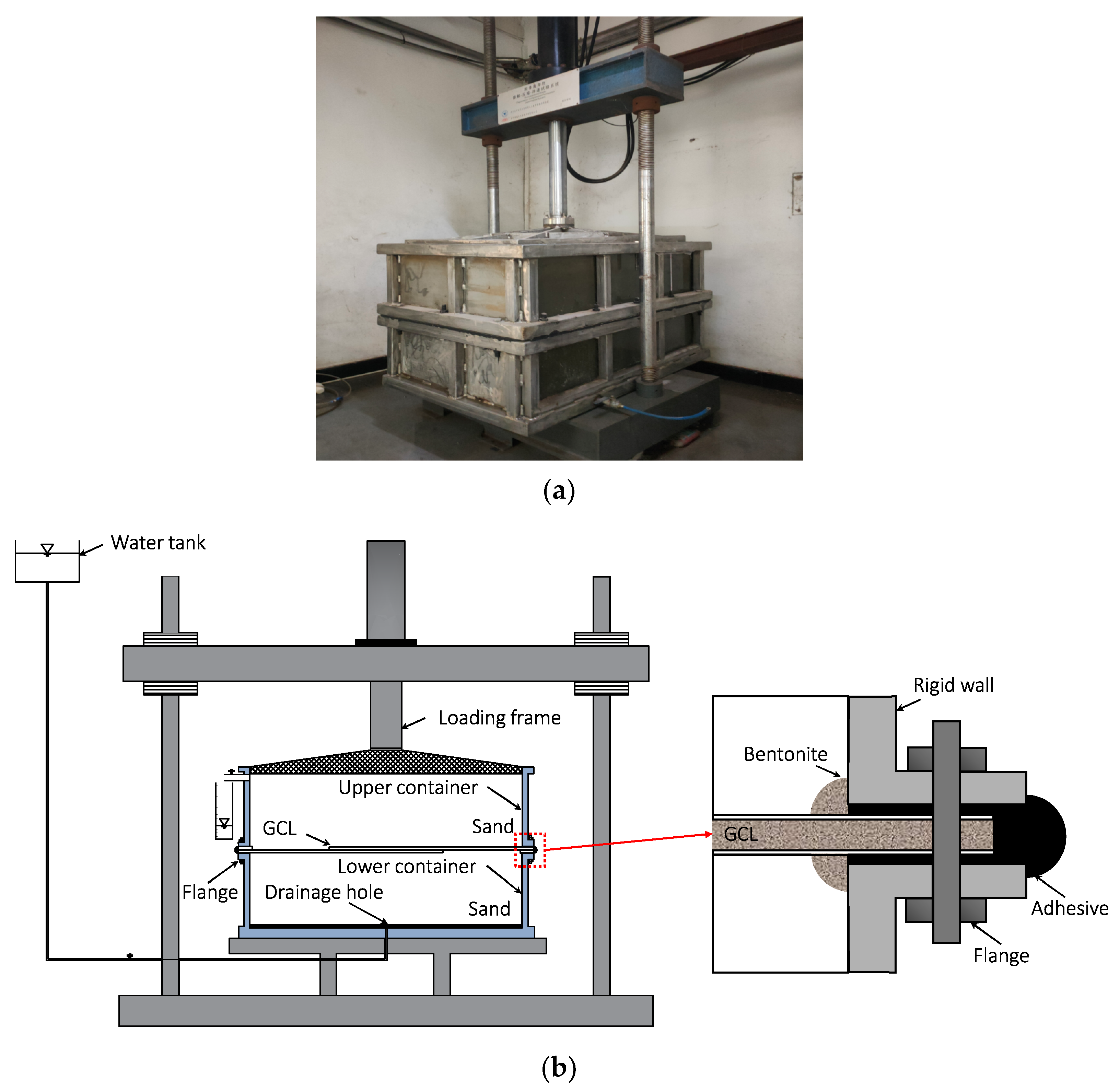
A large-scale model box for testing on the GCL overlap was developed. The main advantage of the model box over the flexible wall permeameter was that full field-scale overlaps widths could be tested over a broad range of confining stress. The edge effect on the hydraulic behavior of the GCL overlap could be reduced. Figure 2 shows a photo and a schematic diagram of the apparatus. It had two rectangular containers, both of which had an internal dimension of 1.2 m × 0.7 m × 0.35 m. Containers were connected via flanges and bolts. The upper container had a lid, which was fixed to a loading frame. A major confining stress of 245 kPa could be provided. To allow the water to flow from the bottom to the top, a water tank providing a constant hydraulic head of up to 10 m was connected to the bottom of the lower container and a drainage hole was at the top of the upper container. The flow was provided in an opposite direction of the gravity in case of flushing bentonite out.

3.3. Test Setup and Procedures

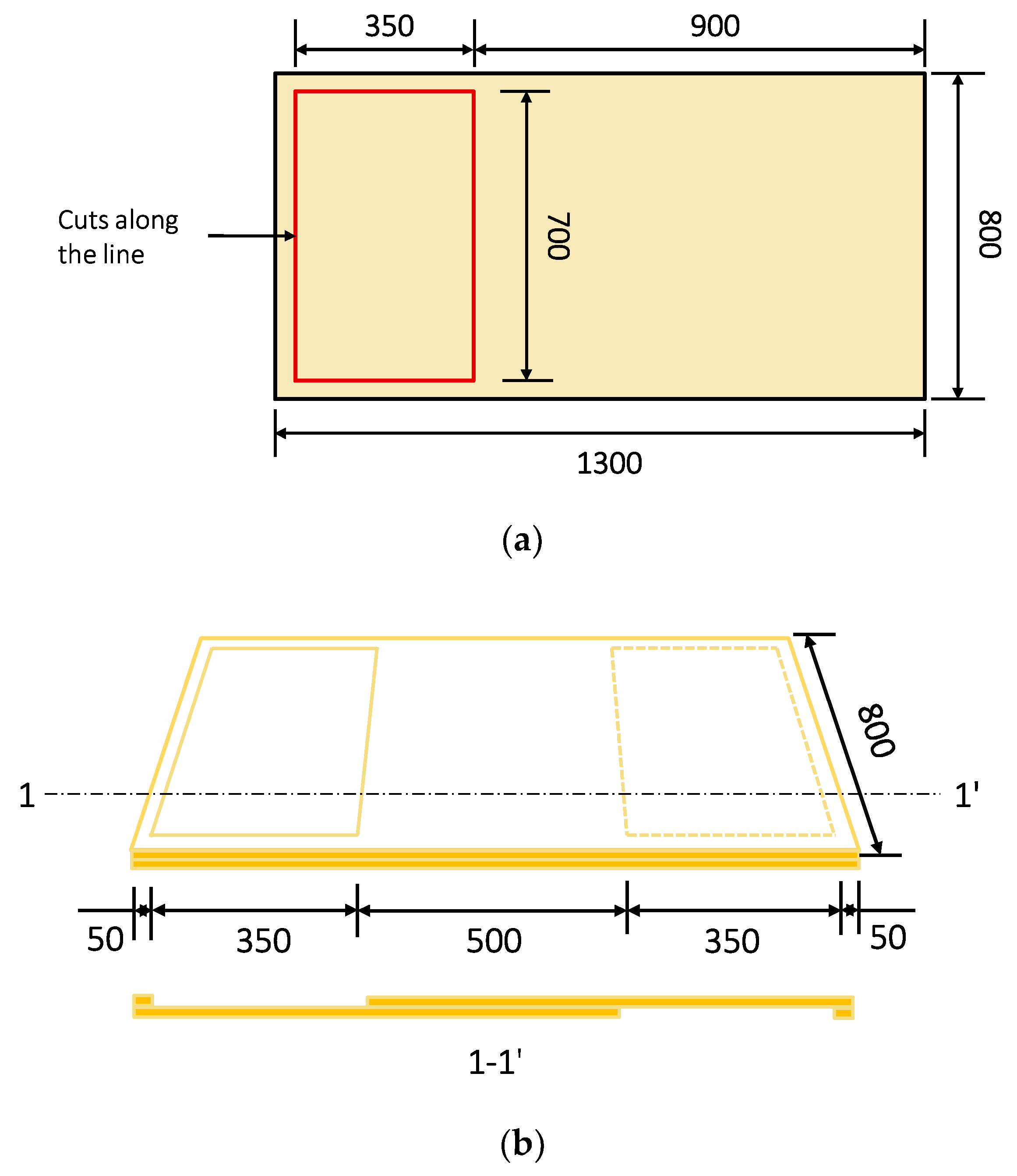
Figure 3 presents schematic diagrams of how the GCL overlap is sampled. A rectangular shape was marked and extruded using a cutter allowing minimum disturbance to the bentonite within the GCL. Two specimens overlapped, and the overlapped portion of the GCL had a size of 0.5 m × 0.7 m. For supplemental bentonite adopted in Test S1, water and bentonite were mixed with a water-to-bentonite ratio of 19:1. A total amount of 700 g bentonite paste was applied at the overlap.
To prepare for the model, coarse silica sand was first pluviated into the lower container. An average dry density of 1430 kg/m3 corresponding to the relative density of 32% was achieved. Then, the GCL overlap sample was placed between two containers, and it protruded out of the containers. The edge of 0.05 m was sealed with adhesive and flanges. A bead of bentonite was pushed around the circumference of the sample to enhance the sealing (Figure 2). The same procedure of pluviation for sand was repeated in the upper portion of the container. Thus, two overlapped GCLs were sandwiched with 0.35 m thickness of sand layers. The water elevation in the tank was then increased in steps to fully saturate the model.

3.4. Flow Flux through the Overlapped GCL Panels

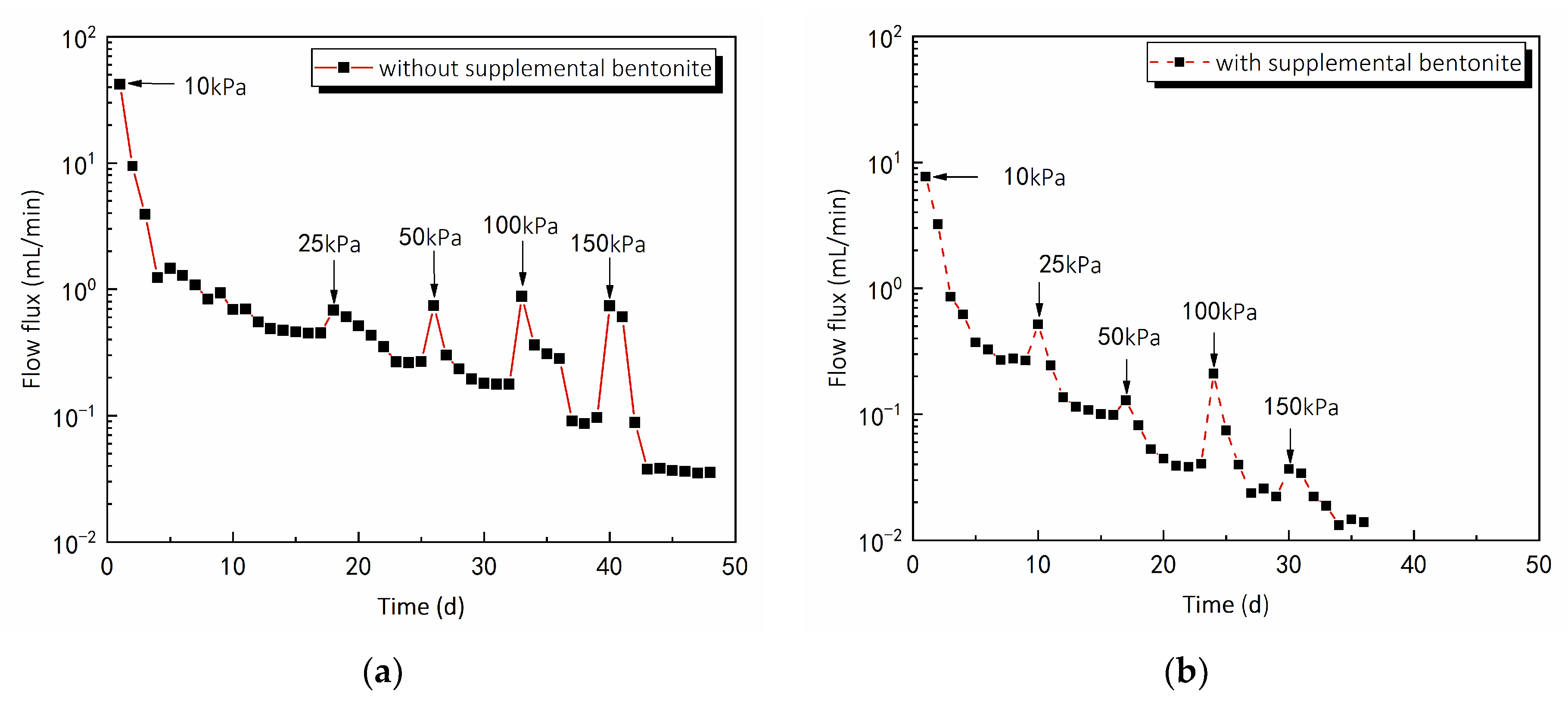
Figure 4 shows measured total flow flux (q1) histories through the overlapped GCL panels under the p of 10, 25, 50, 100 and 150 kPa for test S0 and test S1. In test S0, q1 decreased from 0.45 to 0.035 mL/min when the p rose from 10 to 150 kPa. The higher p could compress both layers of the GCL and the interface of supplemental bentonite reducing the number of pores available for water. These resulted in a decrease in q1. The flow flux increased suddenly at the beginning of each loading stage. This phenomenon occurred because the major loading rate of 0.0012 mm/min was higher than 0.001 mm/min, so an undrained condition was achieved [26], leading to an increase in pore water pressure. The q1 increased sharply as the pore water pressure rose. After the excess pore water dissipated, q1 decreased at a reduced rate and was maintained until the next loading stage. A similar phenomenon was observed in test S1. Overall, q1 decreased from 0.27 to 0.013 mL/min when the p increased from 10 to 150 kPa.
For the analytical calculation, an approach proposed by Athanassopoulos et al. [27] was adopted to interpret the flow mechanism at the GCL overlap. It assumed that (1) the total flow (q1) through the overlapped GCL panels contained the vertical flow through (qiv) and outside (qov) the overlap and the horizontal flow (qih); (2) the qiv and qov followed Darcy’s law. Based on these assumptions, the qih could be assessed from the q1 (Figure 4), hydraulic conductivity of the GCL to water (kGCL; Figure 1), the hydraulic gradient in (iin = 0.63 for the test S0 and 0.60 for the test S1) and outside (iout = 1.27 for the test S0 and 1.20 for the test S1) the GCL overlap and corresponding cross-sectional areas (Ain = 0.4 m2; Aout = 0.64 m2).
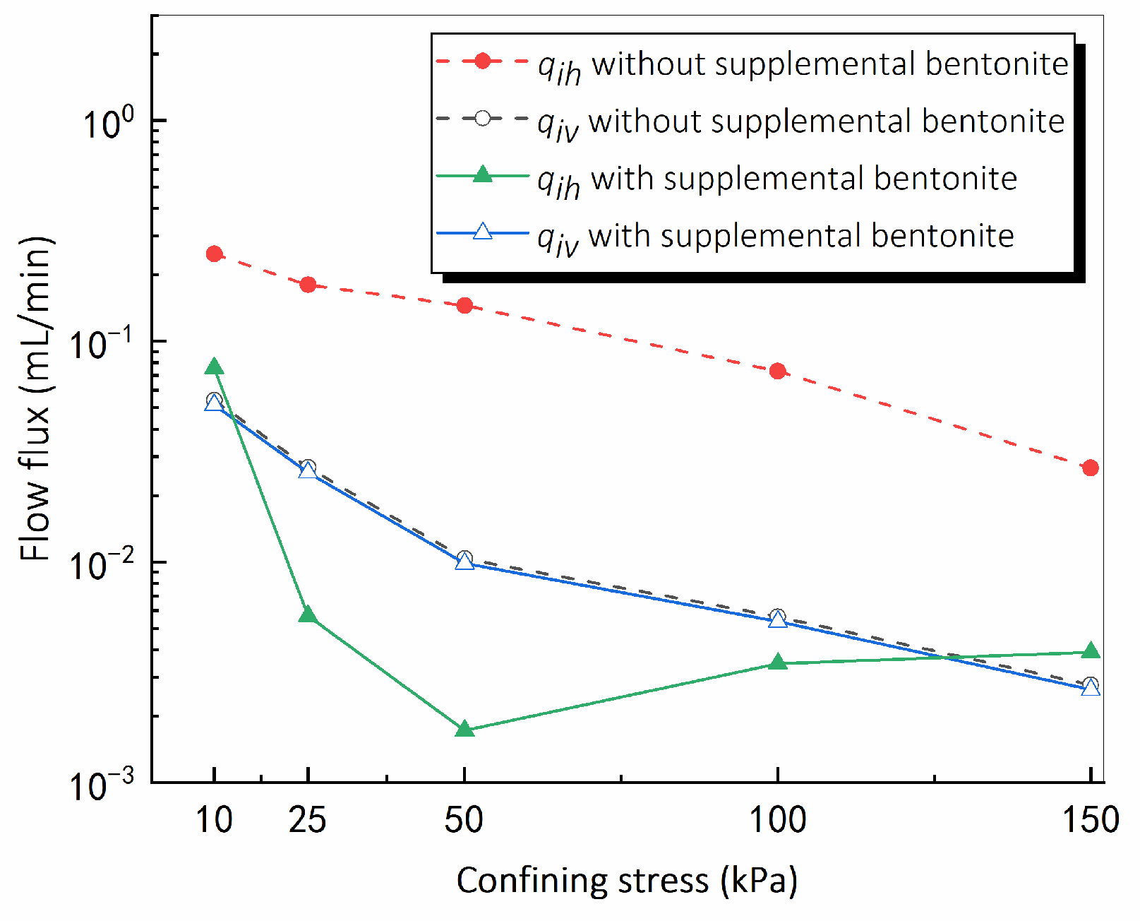
Figure 5 shows the calculated stress-dependency horizontal (qih) and vertical (qiv) flow flux through the GCL overlap with an interface with and without supplemental bentonite. In test S0, qih decreased from 1.8 × 10⁻¹ to 2.5 × 10⁻² mL/min and qiv dropped from 4.5 × 10⁻² to 2.5 × 10⁻³ mL/min when the p increased from 10 to 150 kPa. The flow through the GCL overlap without the supplemental bentonite mainly consisted of the horizontal flow rather than the vertical flow under various levels of p. Results also demonstrated that qih through the GCL overlap with supplemental bentonite paste was less than that without any paste at all five levels of p considered. According to the observations after the test (Figure 6), the supplemental bentonite paste extruded from the interface under the p and wrapped the fibers of the geotextiles, making it difficult for horizontal flow to permeate through the GCL overlap.
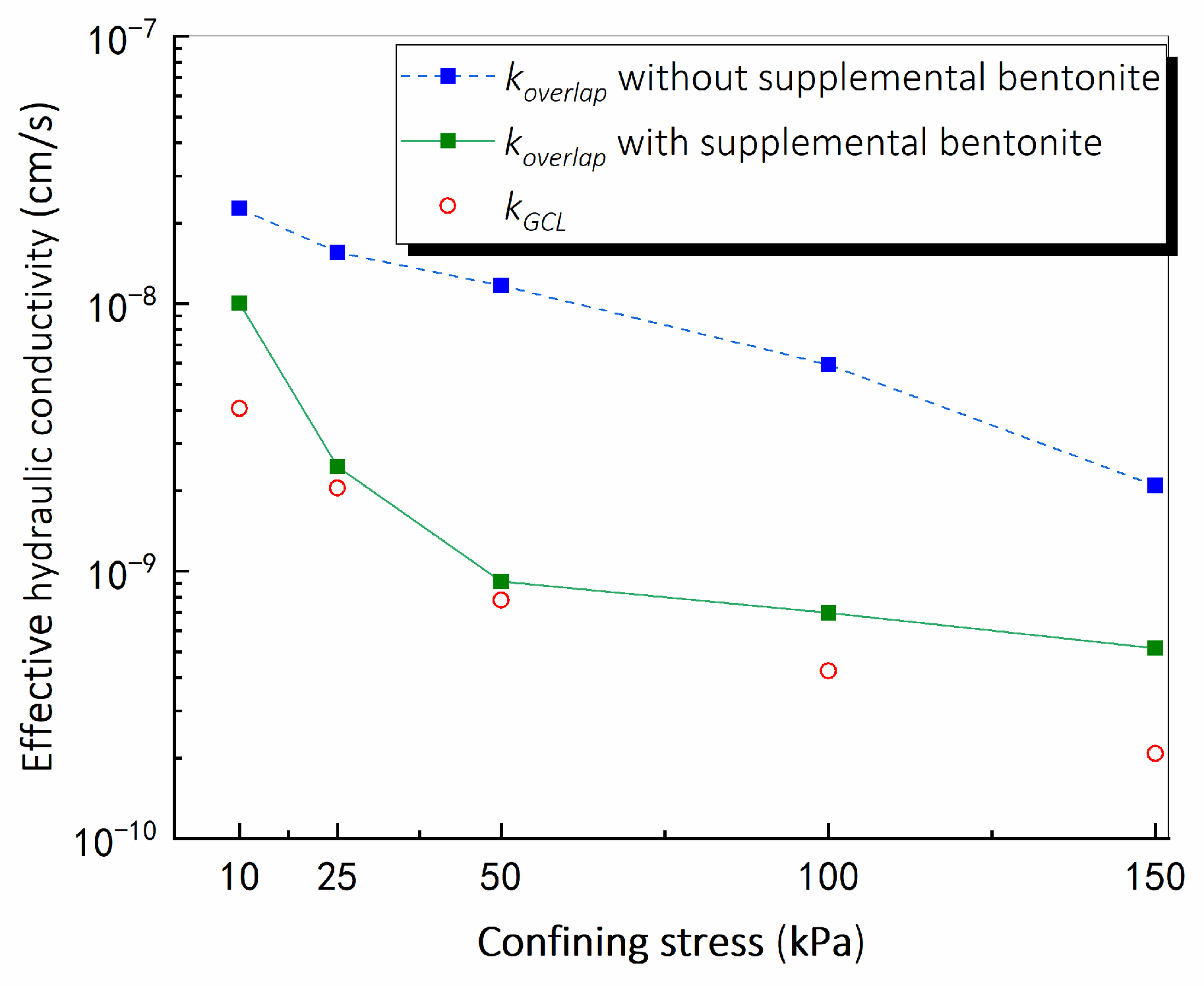
The effective hydraulic conductivity of the GCL overlap (koverlap) was proposed, which was calculated as the flow flux through per unit area of the GCL overlap per unit of hydraulic head. There was a reduction of the power of one in permeation as the p increased from 10 to 150 kPa in both tests (Figure 7). This might result from the reduction in void ratios along with the increase in the seepage path with the increase of the p in the GCL overlap. Generally, the koverlap in test S1 was less than that in test S0 under all levels of p. At the low confining stress of 10 kPa, the koverlap was 4 × 10⁻⁹ cm/s for a GCL overlap with bentonite paste added to the overlap, indicating a decrease of 60% as compared with 1 × 10⁻⁸ cm/s for a GCL overlap with no bentonite. It was evidenced that the addition of supplemental bentonite paste had contributed to enhancing the sealing properties of the GCL overlap at the p over 10 to 150 kPa.

4. Numerical Modeling of the Soil–Bentonite Cutoff Wall Connected with the GCL

The objective of the numerical modeling was to make predictions to the performance of the SB cutoff wall connected with GCLs based on laboratory test data available at the time of the prediction. To solve the considered problem, represented by the mechanism of the preferential flow at the GCL overlap in the sand under the hydraulic head and confining stress, the following study employed the existing fracture model simulating the preferential path at interfaces.

4.1. Mathematical Formulation

It assumes that seepage through the GCL and adjacent soil followed Darcy’s law. In the GCL and adjacent sand, where water flows through a porous medium, Darcy’s law reads:
· ( ρ w v ) = Q m ,
where ρ w is the water density; Q m is the increment of the flow mass; v is the flow velocity in porous, which is related to the coefficient of permeability of porous (K), dynamic viscosity coefficient of water ( μ ), pore water pressure ( u ) and gravity ( g ). It takes the form:
v = K μ ( u + ρ w g ) .  
As in the case where two GCLs separate, the preferential flow may occur, causing the process to be faster in the preferential path than the average water movement bypassing most of the matrix. The formulation describing the preferential flow through the interface is expressed as:
· ( d · ρ w v T ) = d · Q m ,
where d characterizes the equivalent pore size of the interface, and the velocity tensor of the interface ( v T ) is proposed as:
v T = K f μ ( u + ρ w g ) ,
where K f is the equivalent coefficient of permeability of the interface, which can be obtained with the Cube Law as:
K f = d 2 12 f f ,
where f f is the coefficient of roughness and is taken as 1. It is noticed that the liquid flow at the GCL overlap is governed by d, which is in the range of 0.001–1 mm. The determination and calibration of d will be discussed in the following section.
The governing equation of contaminant transport with time (t) is as follows:
R d d n f C t = T ( d n f D d T C v T C ) ,
where Rd is the retardation factor; nf is the porosity; C is the contaminant concentration; Dd is the diffusion coefficient.

4.2. Model Calibration

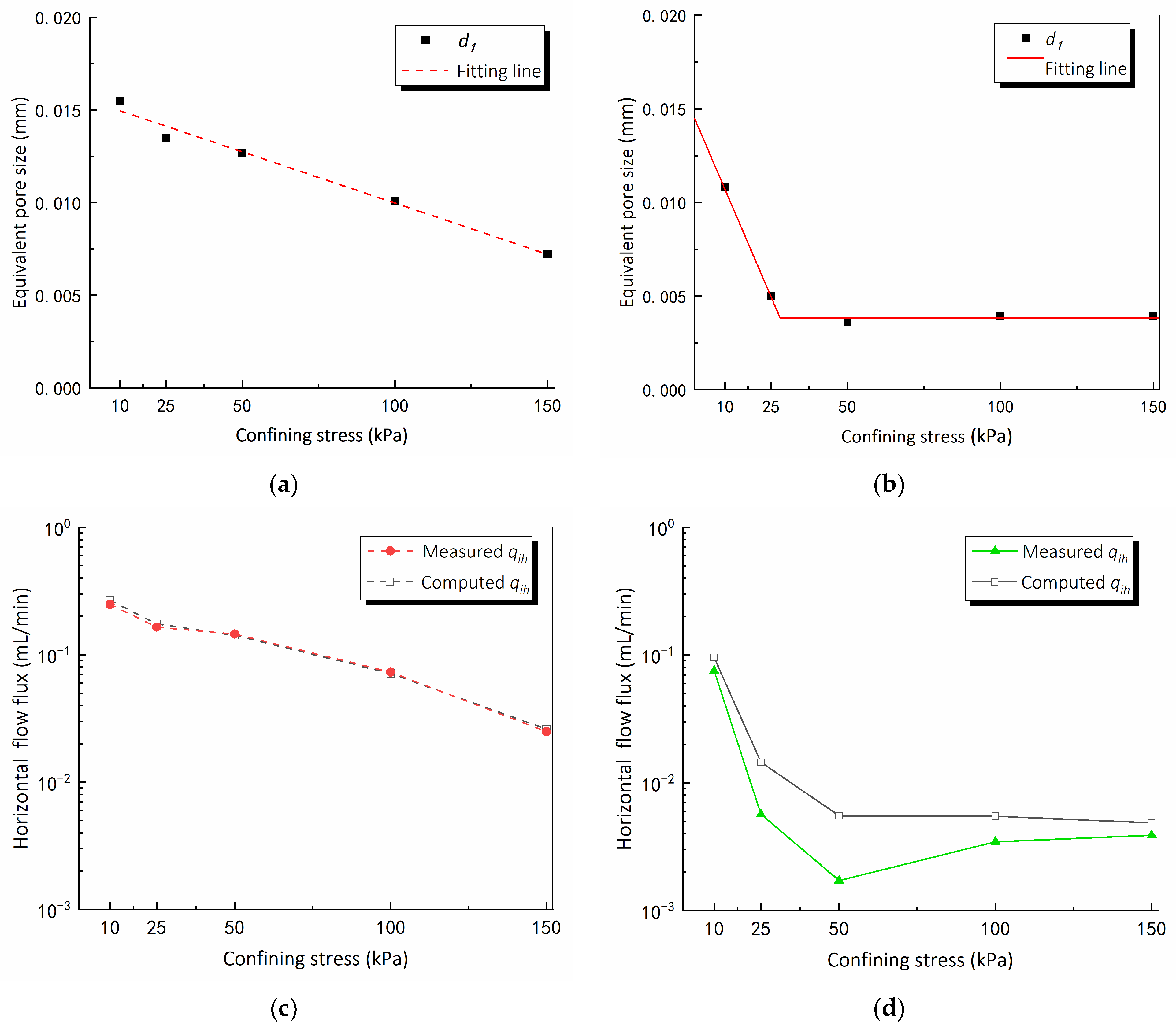
Initial sensitivity analyses revealed that the flow flux was more sensitive to the equivalent pore size of the GCL–GCL interface (d1) compared to those of vertical (d2), horizontal (d3) and inclined (d4) sand–GCL interfaces. The following study only focused on the GCL–GCL interface aspect of the GCL overlap liquid flow mechanism problem. d2d4 were then set as the mean value of the typical range, being 0.01 mm. Values of d1 for the interface layer with and without supplemental bentonite were determined by matching numerical to experimental flow flux.
As shown in Figure 8a, the linear relationship between the d1 and confining stress (p) was used for the GCL overlap with an interface layer without supplemental bentonite. For the GCL overlap with an interface layer of supplemental bentonite, the bi-linear d1 distribution was proposed, where d1 decreased linearly at p less than 25 kPa and then remained constant as p increased. Figure 8a,b compared measured and computed horizontal flow flux using the d1 distributions. The model without the supplemental bentonite matched well with the measured flow behavior. A similar trend was obtained for measured and computed horizontal flow flux varying with the confining stress through the GCL overlap with the supplemental bentonite.

4.3. Finite Element Model Features

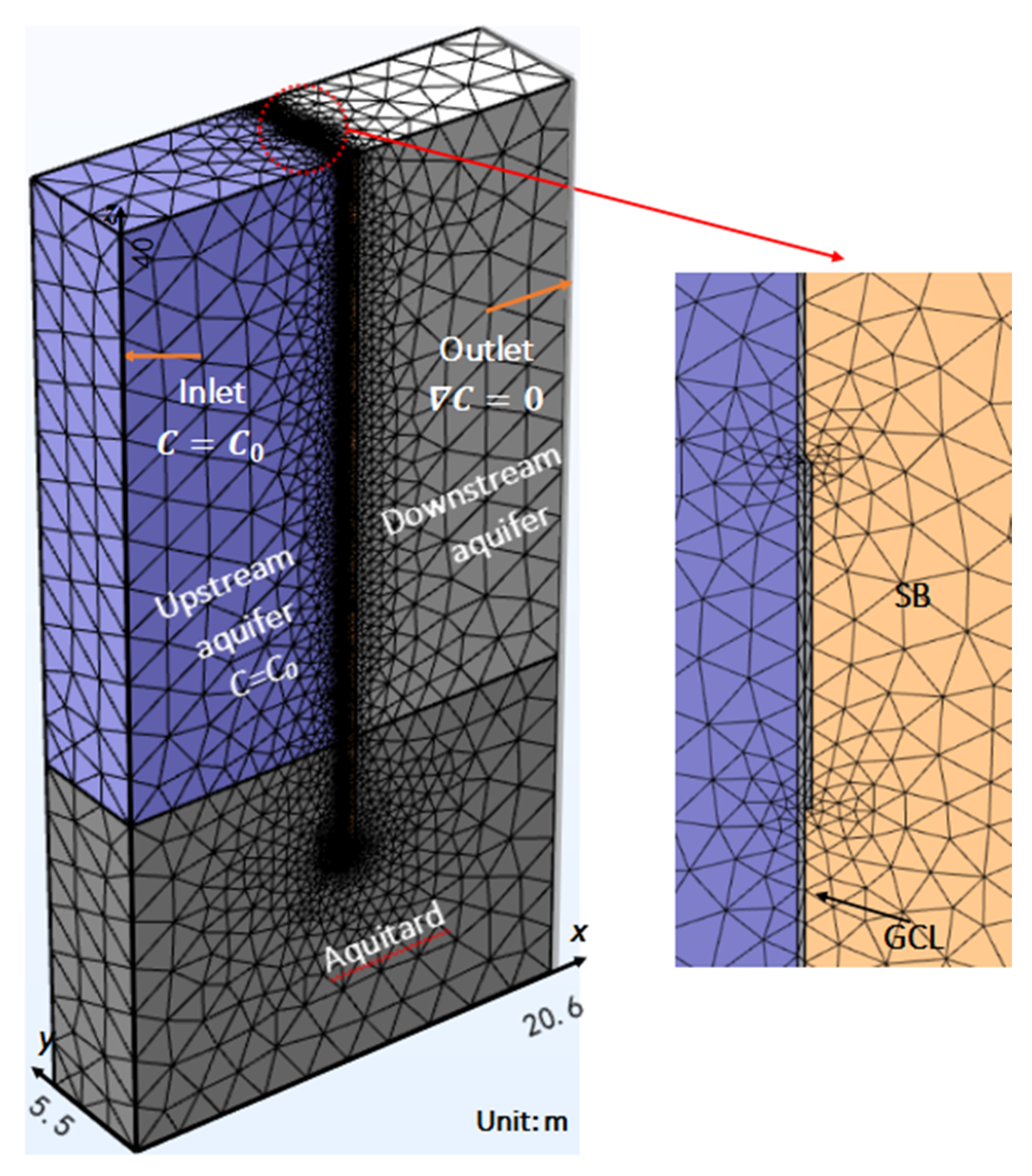
The finite element (FE) modeling was employed and built on the Comsol Multiphysics platform. Figure 9 shows the geometry of the SB cutoff wall connected with the GCL and meshes details of the 3-dimensional FE model. The cutoff wall was installed through an aquifer layer of 25 m in thickness. It was 5.5 m long, 0.6 m wide and 30 m high with 5 m embedded into the aquitard layer. Two GCL panels at an overlap length of 0.5 m were at the upstream side of the wall. The finite element type of linear triangular mesh was chosen to capture the flow around the preferential flow paths. Initial mesh refinement analysis revealed that the size of the FE elements adopted did not introduce any mesh size effect on the calculation accuracy.
For the hydraulic boundary conditions, constant heads of 41 and 40 m were set at the upstream and downstream sides of the wall, respectively. No water was allowed to flow through the sides of the model. A pollution source of Pb(II), being 10 mol/m3, was added to the left-hand side of the boundary.

4.4. Parameters

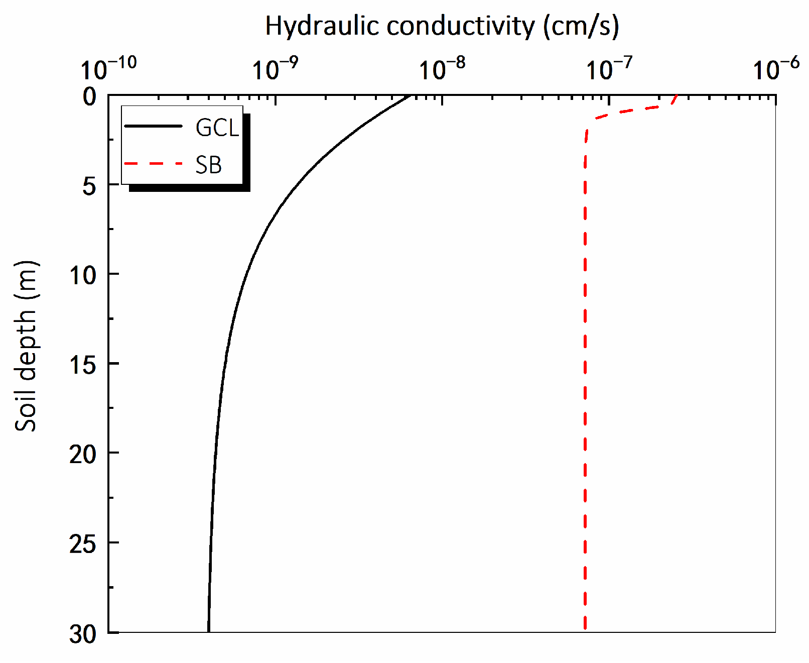
The vertical profiles of the stress-dependent k for the GCL and the SB wall (kSB) are shown in Figure 10. In order to determine the hydraulic conductivity, firstly the p distribution in the cut-off wall was predicted via the model proposed by Li et al. [19] with the interface friction angle ( i n t e r = 30°), effective unit weight ( γ s b = 9.3 kN/m3) and Poisson’s ratio (v = 0.3; Tong et al. [28]). Secondly, the kGCLp curve (Figure 1) and kSBp relationship [29] were employed to determine the vertical profile of the kGCL and kSB, respectively. The aquifer layer was assumed to be homogeneous with k = 3 × 10⁻⁵ cm/s. The k of the aquitard layer was 1 × 10⁻⁸ cm/s.
For properties on the transport of pollutants for the GCL, the diffusion coefficient (Dd) was 3 × 10⁻¹⁰ m2/s [30]. The retardation factor (Rd) for linear adsorption was chosen as 15 [31]. Other related parameters are summarized in Table 3.

4.5. Results and Discussions

4.5.1. Relative Concentration in the GCL–SB Composite Cutoff Wall with Supplemental Bentonite at the Overlap

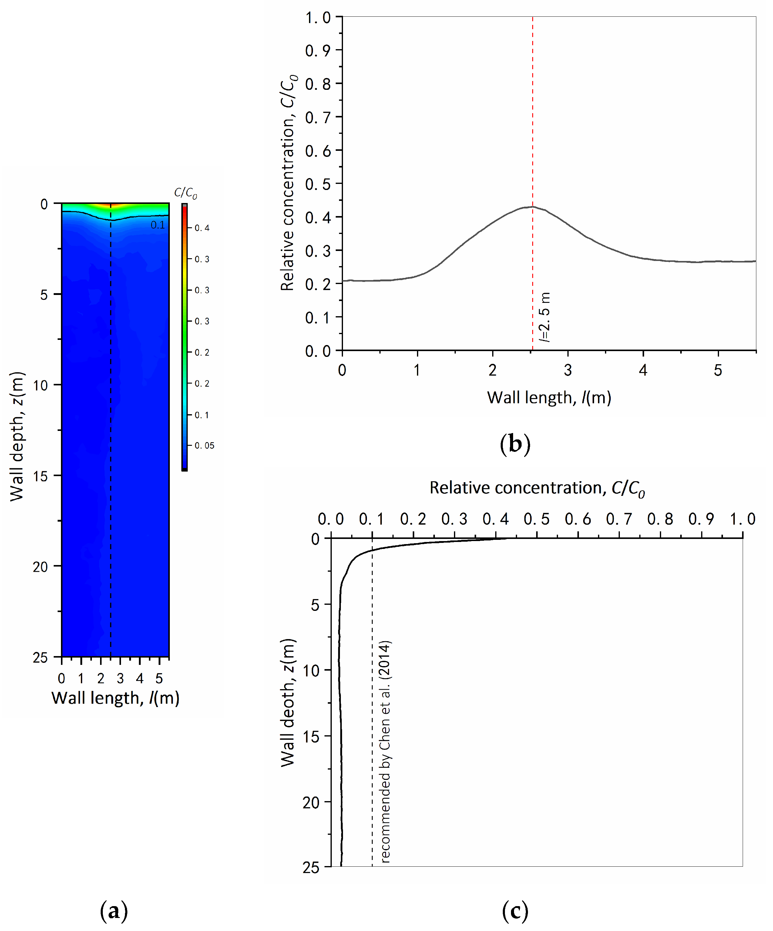
Figure 11 shows the contour and distributions of the relative concentration for Pb(II) on the outboard side of the GCL–SB composite cutoff wall with supplemental bentonite at the overlap. As shown in Figure 11b, the relative concentration along the wall length increased from 0.21 at one end to 0.43 in the middle and reduced from this peak value to 0.27 at the other end. This phenomenon happened as a result of preferential paths, causing the process of leachate migration faster through the overlapping zone than the average contaminant movement bypassing the non-overlapping area. Figure 11c illustrated that the relative concentration decreased sharply from 0.5 at the soil ground to 0.1 at a depth of 0.9 m and reduced slightly with the depth in the deeper regions. This variation was consistent with profiles of hydraulic conductivity for the GCL and SB wall against the wall depth (Figure 9). It could be seen that the breakthrough was made at the shallow 0.9 m depth in the overlapping area where the amount of concentration was more than 10% of the source concentration [32], with consideration that the depth of the groundwater table is generally greater than 1 m, where the soil stress is higher corresponding to a lower koverlap. Under this circumstance, it is unlikely that the breakthrough is made; in other words, the GCL–SB composite cutoff wall with supplemental bentonite paste at the GCL overlap will exhibit a good performance in containing groundwater contaminants in the field.

4.5.2. Effects of Supplemental Bentonite Applied at the GCL Overlap

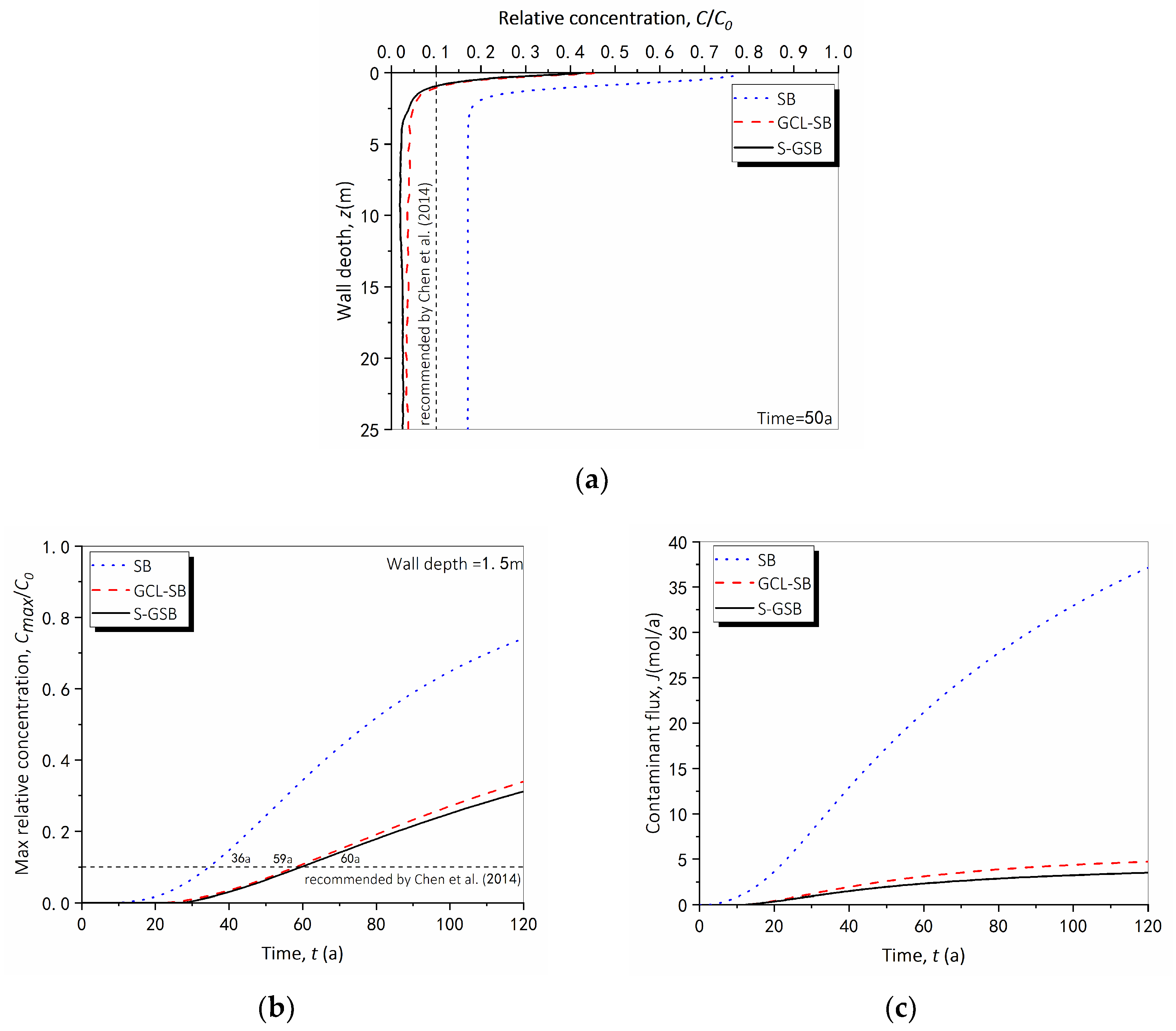
Figure 12 shows the effects of supplemental bentonite applied at the GCL overlap on (Figure 12a) vertical profiles and (Figure 12b,c) time histories of the contaminant concentration. As shown in Figure 12a, the relative concentration exceeded 10% of the source concentration along the depth of the SB wall, which meant that the breakthrough was made for the entire vertical barrier in 50 years. The breakthrough depth for the composite wall with no supplemental bentonite was 1.1 m. Compared with this value, it moved upward to 0.9 m for that with supplemental bentonite paste at the overlap. As for the time histories, the contaminant displayed a nonlinear increase in the maximum relative concentration versus the time for both SB and composite walls (Figure 12b). The breakthrough time for the GCL–SB composite cutoff wall was 64% longer in comparison with that of the SB wall. The GCL overlap with supplemental bentonite paste (denoted as S-GSB) displayed a 67% extension in the breakthrough time. With regard to the contaminant flux, it was expected that the application of the supplemental bentonite paste at the GCL overlap led to a slower contaminant migration and a lower contaminant flux after 120 years (Figure 12c). The contaminant flux out of SB, GCL–SB and S-GSB walls was 37.1, 4.7 and 3.5 mol/a, respectively. Overall, the use of GCLs could enhance the effect of delaying contaminants for the SB wall to a certain extent, especially when applying supplemental bentonite paste at the GCL overlap.

4.5.3. Effects of Hydraulic Head Applied at the GCL Overlap

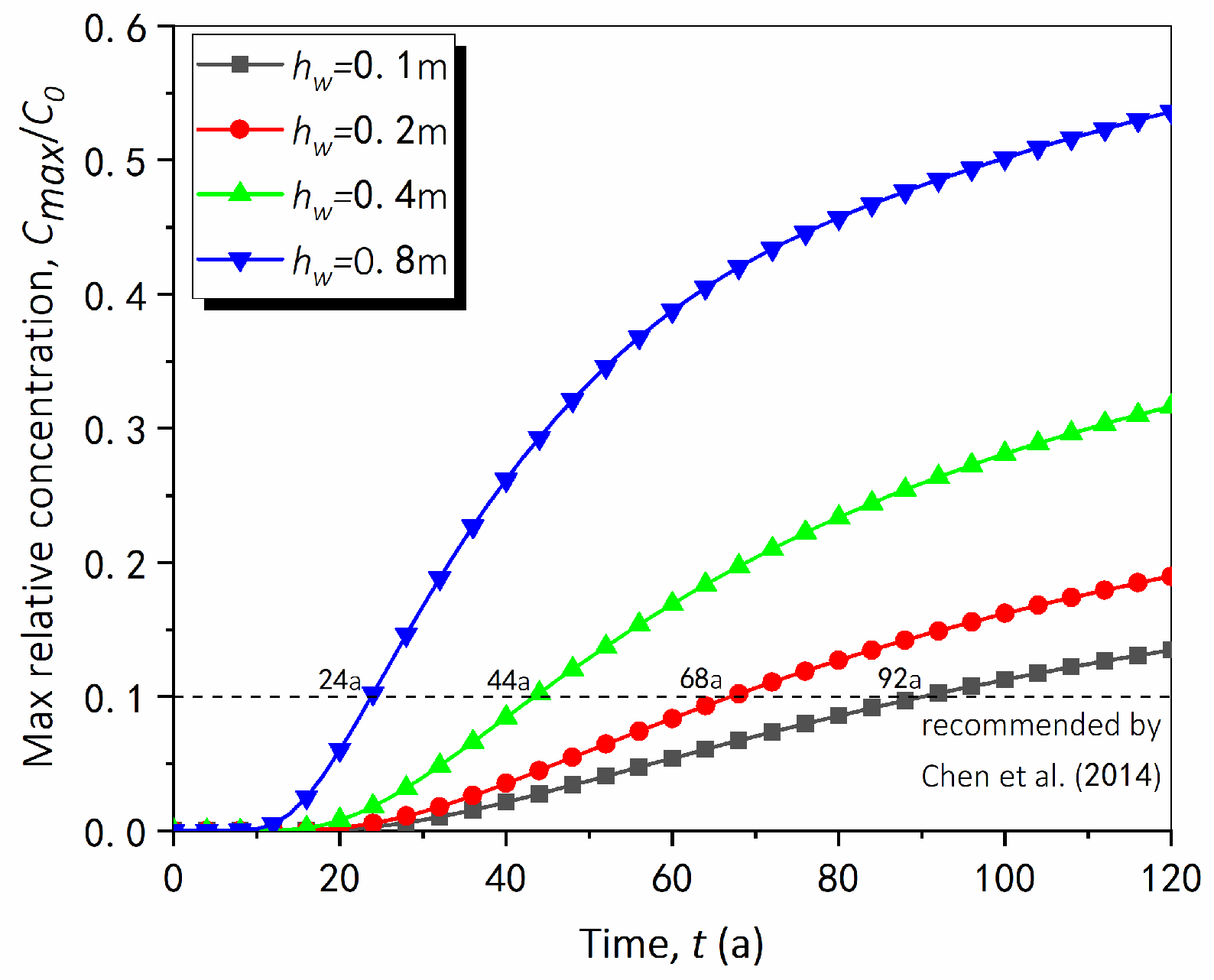
Figure 13 shows the maximum relative concentration histories for the S-GSB cutoff wall under the hydraulic head of 0.1, 0.2, 0.4, 0.6 and 0.8 m. The breakthrough time increased from 24 to 92 years as the hydraulic head decreased from 0.8 to 0.1 m. The breakthrough time computed at 0.1 m hydraulic head was 40.5% longer than that at 0.8 m hydraulic head. This result highlights that the hydraulic head plays an important role in extending the service life of the barrier. It is suggested to reduce the difference in the hydraulic head between the inboard and outboard sides of the S-GSB cutoff wall.

5. Conclusions

This paper presents an investigation into the performance of the GCL overlap in a GCL–SB composite cutoff wall using large-scale model tests and 3-dimensional finite element (FE) simulations. The 500 mm-width GCL overlap with or without supplemental bentonite paste was tested under a constant hydraulic head of 1 m and confining stress ranging from 10 to 150 kPa using a newly developed large-scale apparatus. The performance of the GCL overlap in a 30 m-depth GCL–SB composite cutoff wall exposed to 10 mol/m3 of Pb(II) over 50 years was simulated using the large-scale model test results as a benchmark. The parametric study was conducted to evaluate influential factors, namely supplemental bentonite paste applied at the overlap and hydraulic head, that govern the behavior of the barrier. The following main conclusions can be drawn:
(1)
Compared with the flexible wall permeameter, the developed apparatus with an internal dimension of 1.2 m × 0.7 m can guarantee full field-scale GCL overlap to be tested. The edge effect of the permeameter cell is reduced, and the loss of bentonite near edges due to the cut can be avoided. Additionally, the specimen is placed between two containers and sealed at the edge of 50 mm with adhesive and flanges such that the leakage of water through the container wall can be avoided;
(2)
A negative relationship is demonstrated between the effective hydraulic conductivity and the confining stress of the GCL overlap. As the confining stress increases from 10 to 150 kPa, the effective hydraulic conductivity decreases from 10−8 to 10−9 cm/s. Furthermore, the addition of supplemental bentonite paste with a water-to-bentonite ratio of 19:1 contributes to reducing the effective hydraulic conductivity by 60% compared with that for a GCL overlap with no bentonite;
(3)
The breakthrough time for the vertical barrier was 64% longer by using GCLs in comparison with that of the SB wall. The breakthrough is made for the entire SB wall while at the shallow 0.9 m depth for the composite wall with bentonite at the overlap after 50 years. Considering that the depth of the groundwater table is generally greater than 1 m, the GCL–SB composite cutoff wall will exhibit a good performance in containing groundwater contaminants in the field;
(4)
For engineering practice, it is recommended to extend the breakthrough time of the GCL–SB composite cutoff wall to 92 years by applying supplemental bentonite paste with a water-to-bentonite ratio of 19:1 at the GCL overlap and reducing the difference in the hydraulic head to 0.1 m between the inboard and outboard sides of the barrier.
In the future, centrifuge modeling and/or field tests are recommended to further validate the findings revealed by numerical predictions in this study. Additionally, more attention should be paid to the erosion of bentonite at the GCL overlap in the GCL–SB composite cutoff wall.

Author Contributions

Conceptualization, L.-T.Z. and R.Z.; Formal analysis, L.-T.Z. and Z.-H.D.; Funding acquisition, L.-T.Z., S.-P.X. and Y.-M.C.; Methodology, L.-T.Z., L.-F.C., R.Z. and Z.-H.D.; Project administration, L.-T.Z.; Software, L.-F.C.; Validation, L.-F.C.; Writing—original draft, R.Z.; Writing—review and editing, L.-T.Z. and R.Z. All authors have read and agreed to the published version of the manuscript.

Funding

This research was supported by National Key Research and Development Program of China (2018YFC1802300).

Data Availability Statement

Some or all data and models that support the findings of this study are available from the corresponding author upon reasonable request.

Conflicts of Interest

The authors declare no conflict of interest.

References

  1. Rowe, R.K.; Abdelatty, K. Modelling of contaminant transport through a hole in the GMB. Can. Geotech. J. 2012, 49, 773–781. [Google Scholar] [CrossRef]
  2. Scalia, J.; Benson, C.H. Hydraulic Conductivity of Geosynthetic Clay Liners Exhumed from Landfill Final Covers with Composite Barriers. J. Geotech. Geoenviron. Eng. 2011, 137, 1–13. [Google Scholar] [CrossRef]
  3. Rouf, A.; Bouazza, A.; Singh, R.M.; Gates, W.P.; Rowe, R.K. Gas flow unified measurement system for sequential measurement of gas diffusion and gas permeability of partially hydrated geosynthetic clay liners. Can. Geotech. J. 2016, 53, 1000–1012. [Google Scholar] [CrossRef] [Green Version]
  4. Daniel, D.E.; Trautwein, S.J.; Goswami, P.K. Measurement of hydraulic properties of geosynthetic clay liners using a flow box. In Testing and Acceptance Criteria for Geosynthetic Clay Liners; ASTM International: West Conshohocken, PA, USA, 1997; pp. 196–207. [Google Scholar]
  5. Rowe, R.K.; Brachman, R.W.I.; Joshi, P. Hydraulic performance of overlapped geosynthetic clay liner seams requiring field-applied supplemental bentonite. J. Geotech. Geoenviron. Eng. 2016, 142, 4016067. [Google Scholar]
  6. Weerasinghe, I.A.; Gallage, C.; Dawes, L.; Kendall, P. Factors affecting the hydraulic performance of a geosynthetic clay liner overlap. J. Environ. Manag. 2020, 271, 110978. [Google Scholar] [CrossRef] [PubMed]
  7. Benson, C.H.; Jo, H.Y.; Abichou, T. Forensic analysis of excessive leakage from lagoons lined with a composite GCL. Geosynthet. Int. 2004, 11, 242–252. [Google Scholar] [CrossRef]
  8. Joshi, P.; Rowe, R.K.; Brachman, R.W. GCLs with factory-applied bentonite below geomembrane wrinkle. Environ. Geotech. 2017, 5, 263–270. [Google Scholar] [CrossRef]
  9. Rowe, R.K.; Brachman, R.W.; Hosney, M.S.; Take, W.A.; Arnepalli, D.N. Insight into hydraulic conductivity testing of geosynthetic clay liners (GCLs) exhumed after 5 and 7 years in a cover. Can. Geotech. J. 2017, 54, 1118–1138. [Google Scholar] [CrossRef] [Green Version]
  10. Rowe, R.K.; Brachman, R.W.; Take, W.A. Field measurements of overlap reductions for two reinforced fabric-encased geosynthetic clay liners (GCLs). Can. Geotech. J. 2018, 55, 631–639. [Google Scholar] [CrossRef] [Green Version]
  11. Petrov, R.J.; Rowe, R.K.; Quigley, R.M. Selected factors influencing GCL hydraulic conductivity. J. Geotech. Geoenviron. Eng. 1997, 123, 683–695. [Google Scholar] [CrossRef]
  12. Yu, B.; El-Zein, A. Experimental investigation of the effect of airgaps in preventing desiccation of bentonite in geosynthetic clay liners exposed to high temperatures. Geotext. Geomembr. 2019, 47, 142–153. [Google Scholar] [CrossRef]
  13. Bostwick, L.; Rowe, R.K.; Take, W.A.; Brachman, R.W.I. Anisotropy and directional shrinkage of geosynthetic clay liners. Geosynth. Int. 2010, 17, 157–170. [Google Scholar] [CrossRef]
  14. Kevern, J.T. Evaluating permeability and infiltration requirements for pervious concrete. J. Test. Eval. 2015, 43, 544–553. [Google Scholar] [CrossRef]
  15. Brachman, R.W.; Rowe, R.K.; Take, W.A. Reductions in GCL overlap beneath an exposed geomembrane. J. Geotech. Geoenviron. Eng. 2018, 144, 04018094. [Google Scholar] [CrossRef]
  16. Estornell, P.; Daniel, D.E. Hydraulic Conductivity of Three Geosynthetic Clay Liners. J. Geotechn. Eng. 1992, 118, 1592–1606. [Google Scholar] [CrossRef] [Green Version]
  17. Didier, G.; Comeaga, L. Influence of initial hydration conditions on GCL leachate permeability. ASTM Spec. Tech. Publ. 1997, 1308, 181–195. [Google Scholar]
  18. Weerasinghe, I.; Gallage, C.; Dawes, L.; Kendall, P. Liquid flow mechanism at a geosynthetic clay-liner overlap. In Proceedings of the Geosynthetics Conference 2019, Houston, TX, USA, 9–13 February 2019; pp. 221–229. [Google Scholar]
  19. Li, Y.C.; Cleall, P.J.; Wen, Y.D.; Chen, Y.M.; Pan, Q. Stresses in soil–bentonite slurry trench cut-off walls. Géotechnique 2015, 65, 843–850. [Google Scholar] [CrossRef]
  20. Ruffing, D.G.; Evans, J.C.; Ryan, C.R. Strength and stress estimation in soil bentonite slurry trench cutoff walls using cone penetration test data. In Proceedings of the International Foundations Congress and Equipment Expo, San Antonio, TX, USA, 17–21 March 2015; Volume 256, pp. 2567–2576. [Google Scholar]
  21. BS 1377-2; Methods of Test for Soils for Civil Engineering Purposes—Part 2 Classification Tests. BSI: London, UK, 1990.
  22. JG/T 193-2006; Sodium Bentonite Geosynthetic Clay Liner. Standards Press of China: Beijing, China, 2006.
  23. GB/T 5005-2010; Specifications of Drilling Fluid Materials. Standards Press of China: Beijing, China, 2010.
  24. Zhu, B.; Wen, K.; Li, T.; Wang, L.; Kong, D. Experimental study on lateral pile–soil interaction of offshore tetrapod piled jacket foundations in sand. Can. Geotech. J. 2019, 56, 1680–1689. [Google Scholar] [CrossRef]
  25. Bouazza, A. Geosynthetic clay liners. Geotext. Geomembr. 2002, 20, 3–17. [Google Scholar] [CrossRef]
  26. Bolton, M.D. A Guide to Soil Mechanics; Macmillan Press: London, UK, 1991. [Google Scholar]
  27. Athanassopoulos, C.; Yuan, Z.; Trauger, R.J.; Goldenberg, M. Large-Scale Flow Testing through Seamed and Unseamed Samples of a Multi-Component Geosynthetic Clay Liner. In Current and Future Practices for the Testing of Multi-Component Geosynthetic Clay Liners; ASTM International: West Conshohocken, PA, USA, 2013; pp. 62–70. [Google Scholar]
  28. Tong, X.; Li, Y.C.; Ke, H.; Li, Y.; Pan, Q. In situ stress states and lateral deformations of soil–bentonite cutoff walls during consolidation process. Can. Geotech. J. 2020, 57, 139–148. [Google Scholar] [CrossRef]
  29. Zhan, L.T.; You, Y.Q.; Zhao, R.; Chen, C.; Chen, Y.M. Centrifuge modelling of lead retardation in soil—Bentonite cut-off walls. Int. J. Phys. Model. Geotech. 2022, 1–14. [Google Scholar] [CrossRef]
  30. Xie, H.; Lou, Z.; Chen, Y.; Jin, A.; Chen, P. An analytical solution to contaminant advection and dispersion through a GCL/AL liner system. Chin. Sci. Bull. 2011, 56, 811–818. [Google Scholar] [CrossRef]
  31. Yang, K.L. Experimental Study on Water Permeability of Waste Soil-Bentonite Backfill. Master’s Thesis, Zhejiang University, Hangzhou, China, 2019. [Google Scholar]
  32. Chen, Y.M. A fundamental theory of environmental geotechnics and its application. Chin. J. Geotech. Eng. 2014, 36, 1–4. [Google Scholar]
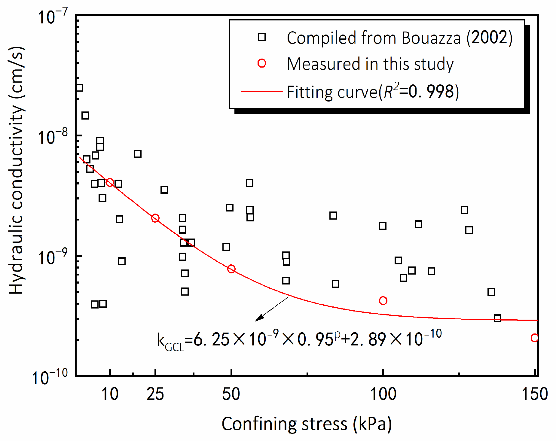
Figure 1. Variations of hydraulic conductivity of the GCL versus confining stress [25].
Sustainability 15 01886 g001
Figure 2. A (a) photo and a (b) schematic diagram of the model setup for the large-scale model test.
Sustainability 15 01886 g002
Figure 3. Schematic diagrams of (a) the specimen sampled from the GCL material and (b) the setup of the GCL overlap. All dimensions in mm.
Sustainability 15 01886 g003
Figure 4. Measured flow flux (q1) histories through the overlapped GCL panels under the confining stress being 10, 25, 50, 100 and 150 kPa for the model with an interface layer (a) without and (b) with supplemental bentonite.
Sustainability 15 01886 g004
Figure 5. Influences of confining stress on the horizontal preferential flow through the GCL overlap.
Sustainability 15 01886 g005
Figure 6. Photos of (a) the top view of (b) the supplemental bentonite paste at the GCL overlap after test S1.
Sustainability 15 01886 g006
Figure 7. Influences of confining stress on the effective hydraulic conductivity through the GCL overlap.
Sustainability 15 01886 g007
Figure 8. Variations of equivalent pore size and confining stress of the interface (a) without and (b) with supplemental bentonite; horizontal flow flux through the GCL overlap with an interface layer (c) without and (d) with supplemental bentonite.
Sustainability 15 01886 g008
Figure 9. The geometry of the SB cutoff wall connected with the GCL and mesh details of the 3-dimensional FE model.
Sustainability 15 01886 g009
Figure 10. The vertical profiles of the stress-dependent k for the GCL and the SB wall (kSB).
Sustainability 15 01886 g010
Figure 11. (a) Contour and distributions of Pb(II) concentration along the (b) wall length and (c) wall depth on the outboard side of the GCL–SB composite cutoff wall with supplemental bentonite at the overlap over 50 years.
Sustainability 15 01886 g011
Figure 12. (a) Vertical profiles and (b) time histories of relative concentration and (c) contaminant flux in three cutoff walls.
Sustainability 15 01886 g012
Figure 13. Variation of maximum relative concentration with time for different head differences.
Sustainability 15 01886 g013
Table 1. Mineral compositions of the Liao Ning bentonite.
MineralValue
Montmorillonite (%)68.2
Albite (%)23.4
Calcite (%)6.3
Quartz (%)2.1
Table 2. Properties of the Liao Ning bentonite.
ParameterValue
Specific gravity, Gs, (-)2.67
Liquid limit, wL, (-)258%
Plastic limit, wP, (-)31%
Plasticity index, Ip, (-)227%
Particle < 0.075 mm, (-)90%
Swelling index in water, (mL/2 g)25
Swelling index in CaCl2 solution, (mL/2 g)20.5
Filtrate volume, (mL)12.6
Table 3. Contamination transport parameters used in the numerical model.
Soil Layernf (-)Dd (m2/s)Rd (-)
Aquifer0.55 × 10−101
SB 0.62.34 × 10−1015
GCL0.93 × 10−1015
Aquitard0.35 × 10−101
Fracture15 × 10−10/
Disclaimer/Publisher’s Note: The statements, opinions and data contained in all publications are solely those of the individual author(s) and contributor(s) and not of MDPI and/or the editor(s). MDPI and/or the editor(s) disclaim responsibility for any injury to people or property resulting from any ideas, methods, instructions or products referred to in the content.