Article

A Novel Offsite Construction Method for Social Housing in Emerging Economies for Low Cost and Reduced Environmental Impact

1
Department of Construction Engineering and Management, School of Engineering, Pontificia Universidad Católica de Chile, Santiago 6904441, Chile
2
Center for Sustainable Urban Development (CEDEUS), Pontificia Universidad Católica de Chile, Santiago 6904441, Chile
3
Independent Researcher, Santiago 7550601, Chile
*
Author to whom correspondence should be addressed.
Sustainability 2023, 15(24), 16922; https://doi.org/10.3390/su152416922
Submission received: 18 October 2023 / Revised: 9 December 2023 / Accepted: 11 December 2023 / Published: 17 December 2023

Abstract

:
Offsite construction methods have shown many advantages over traditional construction techniques, especially related to efficiency and productivity during the construction phase. Nevertheless, offsite construction generally involves oversizing the internal structure of the modules due to the internal stresses produced during transport and lifting operations, producing an increase in material usage, direct cost, and carbon footprint. In developing countries, the direct cost of social housing is the most important factor determining the feasibility of construction. For this reason, oversizing the internal structure of the modules can play an important role in the adoption of a modern construction technique such as offsite construction systems. In order to solve this issue, a temporary reusable stiffener structure is proposed to allow an economical offsite construction system using a lightweight steel framing structure used in traditional methods. The reusable structure was designed using a finite element method, and the direct cost and carbon footprint of the structure were evaluated. The results show that the proposed construction strategy allows for a low cost and reduced environmental impact due to a lower usage of materials in the modules and the possibility of a circular economy approach to the reusable structure.

1. Introduction

Emerging economies (EEs) and developing countries are facing an important deficit in social housing [1], which implies an increasing demand for affordable and sustainable housing to improve the quality of life of millions of families. However, this problem also occurs in some developed countries like Australia and New Zealand [2], where the housing demand is not currently well served. Moreover, housing accessibility and affordability have also decreased due to several factors and conditions, such as high inflation due to the SARS-CoV-2 pandemic [3] and post-pandemic that caused rapid residential price rises [4], increased housing demand because of significant immigration [5], and more frequent natural disasters due to climate change [6]. As a consequence of the housing deficit worldwide, housing accessibility and affordability is one of the sustainable objectives of the 2030 agenda of the United Nations [7].
In order to solve the housing deficit and affordability issues, improvements in productivity are needed. Particularly in Chile, construction productivity has remained unimproved for almost 30 years [8]. On the other hand, the construction industry accounted for 39% of energy- and process-related greenhouse gas emissions in 2018, 28% of which resulted from manufacturing building materials and products [9]. This means the total life cycle must be considered, so Offsite Construction (OSC) methods—which allow more efficient deconstruction and element reuse, thereby minimising material usage—appear to be a promising construction technique for tackling this problem.

1.1. Developing Countries and Emerging Economies

In developing countries and EEs, according to the United Nations (UN) classification [10,11], there is a significant housing deficit that is increasing over time due to high population growth rates [1], with an annual increase of 1% projected until 2030 [12]. In just one EE, Chile, according to projections from the National Institute of Statistics and the Chilean Construction Chamber, from 2019 to 2035, 2.7 million new housing units will be needed [13], which implies increasing the amount of housing construction to 205% of its current annual capacity.
Considering developing countries and EEs, the social housing deficit can be estimated at over 1 billion units [14]. This growing housing deficit scenario is challenging several countries to urgently promote new construction strategies to face this problem, such as OSC.

1.2. Offsite Construction

OSC can be defined as a construction process that involves prefabrication, modular construction, and modern methods of transport and construction. OSC methods involve either modules or specific building components being produced in a factory and then transported and assembled on the construction site [15]. In industrialised countries, this type of construction philosophy can be considered quite consolidated. However, OSC is still in its early stages in EEs.
The construction industry has been losing efficiency continuously over time [16,17,18]. In EEs, there are even higher levels of inefficiency in construction compared to developed countries because the construction industry has traditionally been very labour-intensive. For example, in Chile, the construction sector has a 52% lower productivity than the Organisation for Economic Co-operation and Development (OECD) average [19]. In this context, OSC appears to be a promising technique to enhance the construction industry in EEs because the system has several benefits compared to traditional construction methods, such as lower capital costs, higher productivity, higher quality, higher safety, lower waste generation during the construction process, and better environmental performance [20,21,22,23,24,25], among others, which represent a more sustainable behaviour of the constructions during his life span.
Developed countries represent around 85% of the peer-reviewed research on OSC. On the other hand, a lack of information about these methodologies in EEs is observed [26]. Many studies on the barriers to implementing OSC have been carried out in markets like United Kingdom [27,28,29,30], India [31,32], China [33,34,35,36,37], Pakistan [38], Singapore [39], Malaysia [29], Australia [29,30], New Zealand [40], Algeria [41], Ethiopia [42], the United States and Europe [30], Latin America and the Caribbean [26], Chile [43], and the world [44]. In this type of research about barriers, several constraints are considered, especially those related to the financial aspects of this type of construction (caused by the lack of access to funding) and technical issues [43]. Regarding the technical issues, a large portion of social housing projects do not have optimal access roads to the construction site [25,45,46]; some of these problems are even prevalent in developed countries due to population growth and the need to carry out additions to existing houses [47].
In Latin America, we found that implemented OSCs are imported from developed countries with no important modifications [25], reflecting a lack of continuity in the I + D process in this area [46]. It is important to avoid unexpected problems in implementing OSC, like the case of Algeria related to materials [41] and in Chile related to the future price of the house as an asset [48], by developing local methodologies to address these aspects.

1.3. Transport and Lifting

In offsite construction of social housing, one critical aspect to consider is the construction site’s accessibility because some roads may present significant slopes, washboarding, and low horizontal curve radii, this being one of the causes of the current global housing affordability problems [3]. These aspects can hinder access by trucks and the cranes used for lifting [49]. Also, the proximity to primary service lines (elevated power lines) could make the construction process difficult and increase time and cost.
The above issues are crucial in EEs due to the deregulation of the land market and deficient or inexistent urban planning, which motivates the intensive use of hillsides by people with low economic resources to construct their homes [50]. Also, lifting is often the most expensive part of the installation process [51]. Those constraints suggest that it is essential to establish border conditions referring to transport limits and verify the viability of the lifting equipment for the worksite [52].
The literature review reveals some issues related to transportation that must be considered during the planning of OSC methods. According to the classification proposed by Correia Lopes et al. [53] related to the prefabrication level, projects focused on expanding existing homes in the United Kingdom using volumetric pods (3D) present significant inconveniences regarding the width of the streets and the traffic interruption necessary for the installation of cranes to lift the pods [47]. Also, some differences arise when panelised building systems (2D) and volumetric modules (3D) are compared, where 3D methods present higher transport costs [30,54,55]. When the use of 3D modules is considered, the distance between the factory and the construction site is crucial to determine the suitability of prefabrication methods over traditional methods [30]. A considerable increase in costs exists when volumetric modules require additional permits for the loading and transport vehicles (oversized cargo) [56]. Furthermore, the comparative advantage of 3D systems over traditional construction methods is nil when the distance from the factory to the construction site exceeds 240–320 km [57]. It is important to mention that the volumetric modules used in bathrooms are a focus only in multi-family buildings, in which the barriers related to machinery availability and access roads are different when compared to other types of volumetric modules.
According to Smith [57], there are several aspects to consider when a prefabrication strategy is developed, including overall dimensions for transport; height, width, length, and weight restrictions; crane capacity and access onsite; lifting point details; the route to the site; details for securing transport; crane selection; crane specifications; lighting gear details and assembly; access routes; and structural loadings, among others [57].
There are many studies regarding transportation, basic concept design, and unit construction, but most of them do not simultaneously explore problems focused on prefabricated housing. A unique study by Salama et al. [56] is probably the only one that considers all of these aspects. From the literature review, it is concluded, based on the authors’ best knowledge, that there are no available studies in this area focused on social housing difficulties in developing countries, where the availability of this type of machinery differs from developed countries.

1.4. 3D Volumetric Modules

Volumetric modules are generally classified based on the constitutive material of their supporting structure into steel building modules, light steel-framed modules, timber-framed modules, and precast concrete modules. Particularly, light steel-framed modules consist of a main frame of structural steel in the corners of the module and a secondary structure of light steel that provides rigidity to the module walls in order to resist the internal stresses produced during the transport and lifting process [58], making this type of house overstructured in comparison to the traditional “in situ” construction methodologies. This problem is presented as a potential limitation in providing low-cost housing in EEs. Also, this feature is relevant because the higher use of materials means an increase in cost and carbon footprint due to more energy consumption during the fabrication process and fuel needed for transport and lifting activities. Thus, the challenge presents itself to allow modular prefabrication without incurring this type of practice.
As finishing materials, plasterboard panels are usually utilised in the light steel- and timber-framed modules, which usually present damage during transport and lifting. There are a few studies in this area focused on the detection of such damage using modulation systems for the plasterboard [59]. Meanwhile, other authors have located sensors in places that commonly suffer damage, such as walls without discontinuities and places near doors and windows, finding some variability between the modelled and experimental results due to the difficulties of adequately modelling plasterboard panels [60,61]. Studies have also been carried out on the screws that connect the plasterboard with the light frame structure, determining that damage is seen in the finishes in displacements close to 0.5 mm [62].
Based on the literature reviewed, the authors identified the following research gaps:
  • There are accessibility barriers to building social housing in developing countries, such as roads that have high slopes and are too narrow for large trucks.
  • Most modular constructions are structurally oversized to resist mechanical efforts due to transport and lifting.
This paper contributes to the state of the art and practice by proposing a new system for modular construction based on an External Temporary and Auxiliary Stiffener Structure (ETASS) that allows for transport and lifting without structurally oversizing the modules. As a result, the structural elements of the modules are reduced; thus, the cranes and trucks needed have a lower lifting capacity, reducing their costs; therefore, the cost of industrialized social housing could be significantly reduced, making them more affordable. Moreover, this system (ETASS) is reusable, which allows us to reduce the long-term carbon footprint.
Considering the whole above context, two research questions regarding the modular construction of social housing arise: how can we overcome the barriers related to accessibility issues? and how can we avoid oversizing the housing structure? These research questions focus on optimizing the housing structure to generate positive economic, social, and environmental impacts. ETASS is proposed to allow for an economical offsite construction system using a lightweight steel framing structure used in traditional methods. The reusable structure was designed using a finite element method, and the direct cost and carbon footprint of the structure were evaluated. The results show that the proposed construction strategy allows lower costs and reduced environmental impacts due to a lower usage of materials in the modules in the context of the material savings in Chile.
It is important to highlight that both research questions are related to the paths of developing affordable, accessible, and environmentally friendly social houses in the EEs, taking into account the three pillars of sustainability (social, environmental, and economic) [63,64].

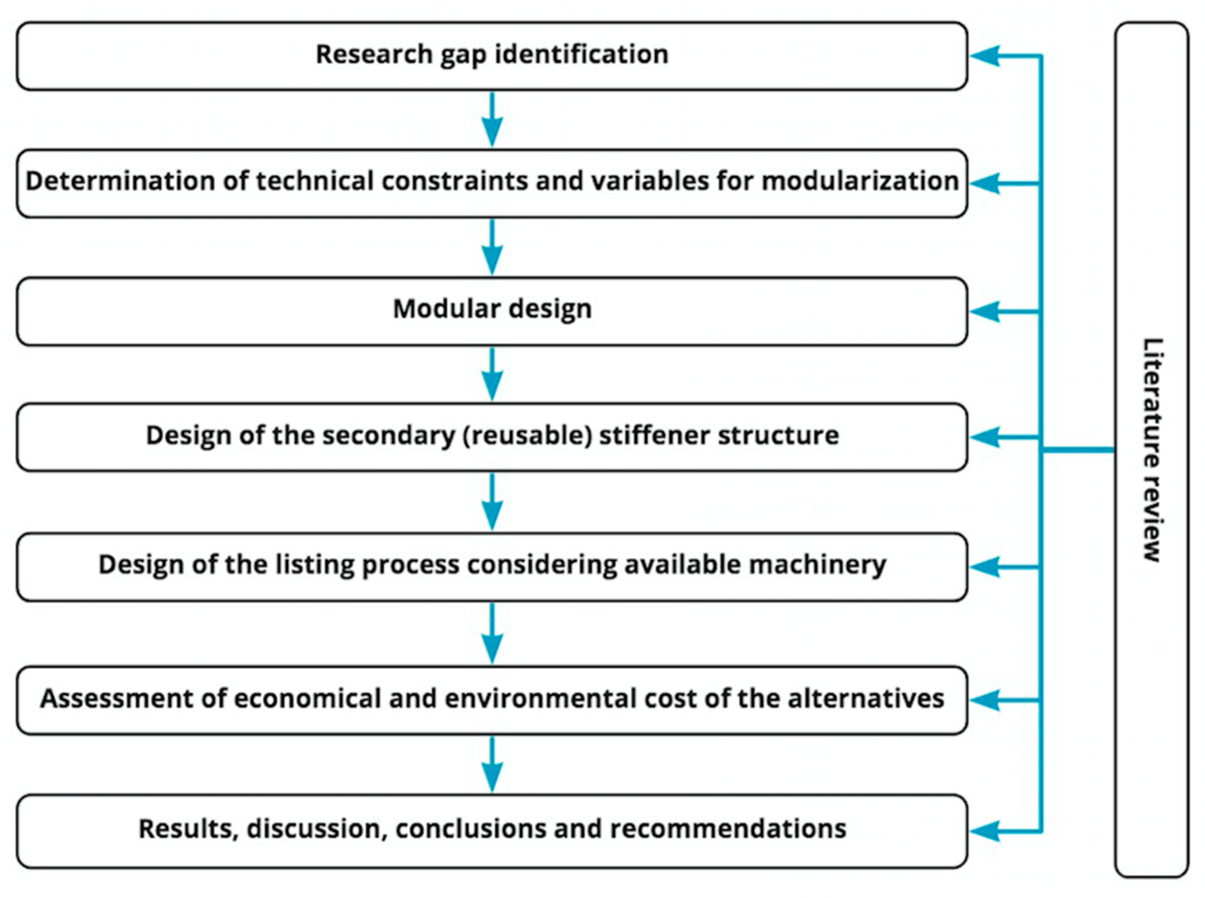
2. Materials and Methods

This research was conducted in seven steps (Figure 1). The first step involved defining the problem and identifying gaps in the current state of OSC. In the second step, Chilean regulations (i.e., maximum allowable transportation load and dimensions, structural and efficiency standards, material specifications, and height clearance of power grid facilities) were analysed to take them into consideration in designing ETASS.
As a third step, the modular design or “modularisation” process was based on the single-family units’ public information (i.e., blueprints, technical specifications) obtained from the Chilean public-market platform [65]. From here, this database was analysed to find representative social housing to be modularised. Thus, the representative housing corresponds to the construction project of 12 houses for victims of the 3 January 2019 wildfire in Limache, Chile [65]. Figure 2 presents images of the construction process and Figure 3 and Figure 4a show the elevation and plan view drawings of the representative house. The existing information related to this project allowed the analysis of various aspects and the quantification of various parameters related to architecture, materials, and structure, among others. The representative or case-study project presents some particularities that reveal some of the barriers found in the literature review. For example, it was developed in the modality of “own site construction” because the houses were built in the same place where the damaged homes were located. This means that the land cost is not included in the economic analysis. Also, due to the project’s size, it does not consider economies of scale, which may be common in other projects. The modularisation process for this research involved dividing the structure into volumetric modules; after that, weights and sizes were calculated.
Integrating the information from the first three steps, in the fourth step, the secondary reusable structure was designed. The objective of this auxiliary structure is to strengthen the modules to avoid damage but at the same time be reused in other modules. The secondary structure was designed using finite element method (FEM) software, specifically SAP 2000 v23.2.0 educational license [66]. The design philosophy considered the maximum displacement outputs reported in the existing literature [62].
With the final design of the secondary structure, together with the geometry of the construction site, interferences, and the access road, the transport and lifting work was modelled using kranXpert 1.9.9.6 demo version software [67] and various types of machinery available in the local market for this type of work. In this step, the construction methodology was proposed for the traditional modular construction process (oversizing the modules to resist internal stress) and also for the new methodology proposed in this paper, which is called the innovative construction process.
In step six, the economic and environmental costs of the two prefabrication options were compared using a life-cycle assessment approach, especially taking into consideration the embodied carbon of the structure (considering the final structure, the temporary structure, and finishing) and the costs involved in fabricating and lifting the modules.
Finally, the results of the design of ETASS and its impact on cost and carbon footprint were analysed in the last step of the methodology. This allowed us to draft conclusions about the practicability of the innovative method and this type of structure (ETASS) for the representative single-family units and suggest recommendations for future studies and related innovations in order to overcome the problems detected in the literature review to facilitate the implementation of OSC.

3. Results

3.1. Determination of Technical Constraints for Modularisation

In order to establish the constraints that limit or influence the modularisation design process of social housing construction, a review of the critical regulatory aspects is summarised in this section.

3.1.1. Current Regulations for the Construction of Social Housing

The Chilean regulation called “Regulations of the Housing Program for the Solidarity Fund for the Choice of Housing—DS49” promotes access to housing solutions for families with social and economic vulnerability through a subsidy granted by the State of Chile [68]. The technical standards for the construction of this type of project [69], the standards of dimensions and minimum uses for furniture [70], and the general regulation for construction [71] also specify the quality, safety, and architectural conditions of the houses built with this regulation’s subsidy.
Regarding the site’s conditions, DS49 establishes an additional subsidy between approximately USD 5600 and USD 14,186 for the construction of retaining walls, slope stabilisation, special foundations, improving salty soils, and massive structural fillings, among other items. These resources apply only to works within the property where the house will be located and cannot apply to interventions in a public space, as in the case of access roads or sidewalks.

3.1.2. Transportation Regulation

Resolution No. 1, published in 1995, of the Transportation and Telecommunications Authority of Chile established the following maximum dimensions for vehicles that circulate on public roads in the country [72]:
  • Maximum exterior width (excluding rear view mirrors):
2.60 [m]
  • Maximum height above ground level:
4.20 [m]
  • Maximum length of a truck with a trailer or other combination:
20.50 [m]
Eventually, the regulation allows oversized and overweight transports, which are not included in the scope of this research.

3.1.3. Interferences Caused by Public Electricity and Telecommunications Networks

The public electricity networks are generally located in the sidewalk between the construction site and the access road and may have a voltage of over 1000 V according to the national standard NSEG 5. E.n.71 [73]. This regulation, in Article 107, indicates the following distances between the sidewalk and the conductors:
  • Minimum height of conductors in neutral:
4.6 [m]
  • Minimum height of conductors in phase:
5.0 [m]
  • Maximum height of all wires:
Not established
The above dimensions are considered as physical constraints for rigging manoeuvres. In the case of telephony or fibre optic cables, the vast majority of the cables are supported by structures that belong to the electrical service concessionaires. They generally follow the rules of these services related to minimum heights. However, they are not mandatory for the public telecommunications service concessionaire but instead constitute only a reference [74].

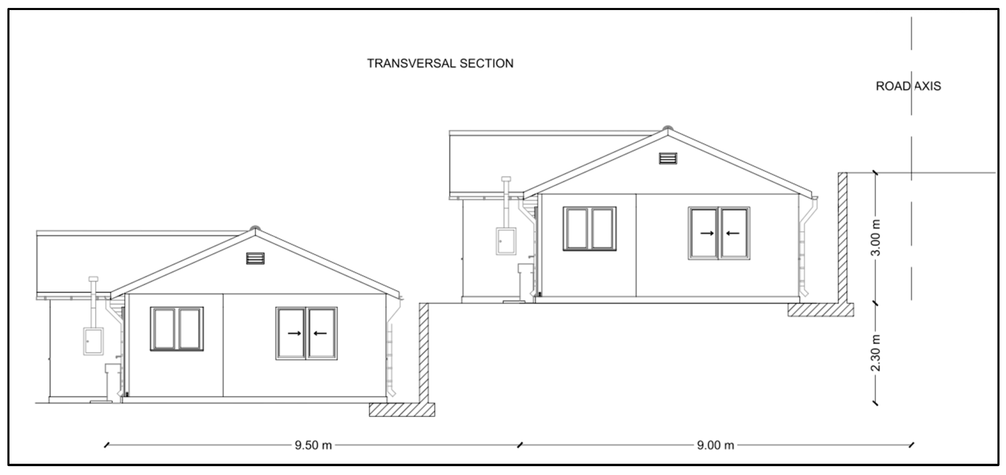
3.1.4. Morphology of the Construction Site

Two types of construction sites have been chosen for this research. They are located in the central region of Chile, specifically in the city of Limache, in the Valparaiso region, and are owned by the families that benefited from the DS49 state subsidy to rebuild the houses destroyed by a significant wildfire on 3 January 2019. Two land pictures are presented in Figure 2.
Concerning the conditions of each construction site, the following aspects must be highlighted:
  • Slopes: The literature indicates that cranes can only work on horizontal surfaces. In cases with gentle slopes or that are not wholly uniform, support platforms for stabilisers are used. Even so, it is pointed out that the maximum slope of the access road cannot be greater than 5% [75].
  • Street width: The cases analysed have 6 m wide streets, so the possibility of extending the stabilisers of lifting equipment to 100% must be verified in each project.
  • Elevation between the access road and construction platform plus maximum horizontal lift distance: These aspects will be analysed based on the maximum load tables provided by the equipment manufacturers.

3.2. Modular Design

Each home’s modularisation was carried out to break down the original architecture into several volumetric modules, considering the maximum widths according to national transportation regulations. The roof structure was left out of the modularisation because, using current construction technology, modules with roofs could not be broken down onsite without compromising their waterproofness. The details of the houses’ modularisation are presented in Figure 4 (both homes have the same floor plan).
According to the information provided by the technical specification platform of the Technological Development Corporation of the Chilean Chamber of Construction [76], the weight of each of the modules was calculated, considering the specific weights of each material according to the catalogues available from manufacturers on this online platform and the following considerations:
  • Finishes like coating mud, joint angles, paint, and tiles are not considered in the calculation.
  • The duplication of the supporting structure that occurs due to adjacent walls between different volumes is not considered.
  • The weight of screws and minor fixings between construction elements is not considered.
  • Only the weight from the finished floor level upwards is considered because the floor structure is made of in situ concrete.
  • For better performance during the transport and lifting process, the weights of the modules assume they were structured without door and window openings.
  • Additional reinforcements to the supporting structure for lifting are not considered.
As an example, the results of the weight calculation of module M-1 are presented in Table 1. According to the results, this module has a weight of 444 kg. This weight is considered as the net load for the rigging design. It is important to highlight that this is the heaviest module of the house because of its size and composition of three faces, including windows and a door.

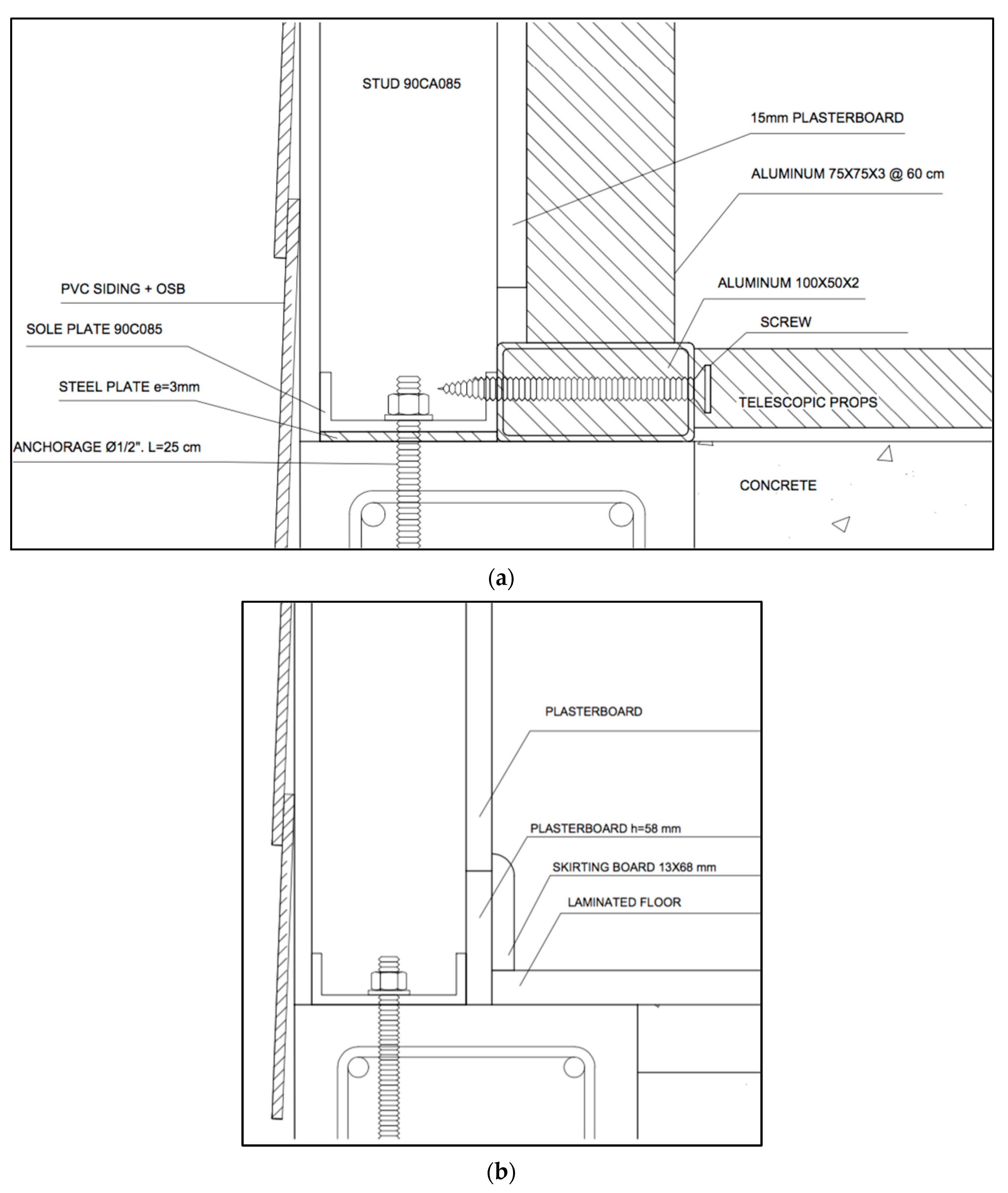
3.3. Design of the External Temporary and Auxiliary Stiffener Structure (ETASS)

An ETASS is proposed based on a conceptual and structural design. This structure must allow the rigging process and stiffen the structure of modules to avoid major displacements during transport and lifting manoeuvres and damage to the finishes.
For the lifting process, four different rigging methods are analysed, all of which consider an individual structural validation due to the different stresses produced:
  • Direct pick points: The crane hook is connected employing slings or cables directly to “pick points” incorporated in the structure, which produces internal forces throughout the structure [57].
  • Wrap-around slings: These support the module from below in two continuous strips, so rigidity is required in the lower part of the structure to avoid damage produced by internal forces and drifts.
  • Spreader bars: These are used to provide lifting forces to act vertically on the structure [57], and they can be implemented considering complex arrangements to have several “pick points.” They produce lower internal forces than the direct pick point method, but they also require structural reinforcements.
  • Trays: These are used for more minor elements, generally called “pods,” and are accompanied by specialised secondary equipment that allows the pods to be moved to their final location [77], which makes reinforcements in the lower part essential.
Some additional considerations for the design are presented below:
  • Each module should be installed adjacent to another by at least one of its exterior faces. Because of that, the rigging accessories should not be located outside the structure in order to avoid damage to the exterior faces of the other modules.
  • In order to avoid oversizing the original structure of the module, the use of hooks tied to the module itself should be discarded.
  • The module does not have a floor structure because the house must have a concrete floor built onsite.
  • The ETASS must be reusable for various architectures and module sizes in order to provide a solution for developing countries with diseconomies of scale in housing construction.
The structure proposed is composed of frames of 75 × 75 × 3, stiffener beams of type C150 × 50 × 3 mm at the top and 100 × 50 × 3 mm at the bottom made of aluminium alloy type AA6060-T6, and a base plate of 3 mm thickness of ASTM A36 steel, on which the module is supported. In order to allow for disassembly and contribution to horizontal rigidity, telescopic props are positioned horizontally. The details are presented in Figure 5, Figure 6 and Figure 7.
The bottom beams of the system are connected directly to the sole plate and the studs by horizontal screws. The top beam connects directly to the top plate using vertical screws. After positioning the module and disassembling the ETASS, the space at the bottom of the interior walls, which has a height of 58 mm, is covered with a 68 mm skirting board. This allows us to include all the finishes in the modules before transport, avoiding in situ finishing work on the walls (Figure 8).
For the structural validation of the system, a finite element method (FEM) model using SAP 2000 v23.2.0 software [66] was developed, taking into consideration the following criteria:
  • The maximum permitted displacements related to the height (h) of the element, according to the regulations in Chile, are 2/1000 × h [78], that is, 4.8 mm. The deformations specified in the regulation are to prevent the collapse of the structure, but not to prevent damage to the finishes, so a maximum deformation criterion of 0.5 mm will be used because it has been determined that 10 mm thick plasterboard panels begin to suffer damage around this value [62]. This is a conservative assumption considering the 15 mm thickness of the actual case modules proposed in this study.
  • An amplification factor of 4.3 is adopted to multiply self-weight in positive and negative directions in two different load combinations, based on the perpendicular acceleration of 32 m/s2 obtained for speeds of 5.6 km/h obtained based on experimental data [79].
  • A transport speed lower than 41 km/h is considered because the damage to plasterboards increases considerably above this range [59]. Thus, a lateral wind pressure of 40 kg/m2 is considered according to the simplified calculation method based on the current regulation in Chile [80].
  • A maximum slope of 12% is considered following the urban road geometric design provisions of current regulations [81].
  • A 178 kgf load applied to the pick points is considered, which corresponds to the horizontal component produced at these points, the product of the module’s dead loads.
  • The following load combinations (combos) are considered for different scenarios included in the model (Table 2 and Figure 9):
In the directions parallel to the plane of the longest walls (U2 and U3), the maximum deformation is 0.43 mm (Table 3), which is less than the deformation at which damage is produced in the plasterboard panels. Therefore, it is considered that the proposed system allows prefabrication, including the specified finishes (mainly painting). The final weight of the proposed structure is 267.54 kgf.
The top of the secondary structure will be structured with pick points, where two pairs of slings will be placed that will go from the pick points to a 3.7 m long spreader bar, according to Figure 10. Considering a total weight of the structure–module system of 711.09 kg and a minimum angle of 30° between the slings that join the ends of the spreader bar with the hook of the crane, we have the following design of the spreader bar:
C = tan 30 ° × 711.09   k g = 410.55   k g f ;   λ = K l r = 1 × 360   c m 3.49   c m = 103.14
C C = 2 × π 2 × E σ y = 2 × π 2 × 2100000   k g / c m 2 2500   k g / c m 2 = 128.70 < 103.14 σ c = 891.92   k g f / c m 2
891.92 k g f c m 2 × 9.29   c m 2 = 8285.96   k g f > 711.09   k g f O K S p r e a d e r   B a r : S t e e l   A 36   O   4 × 7.29 k g f m 2 30   k g f

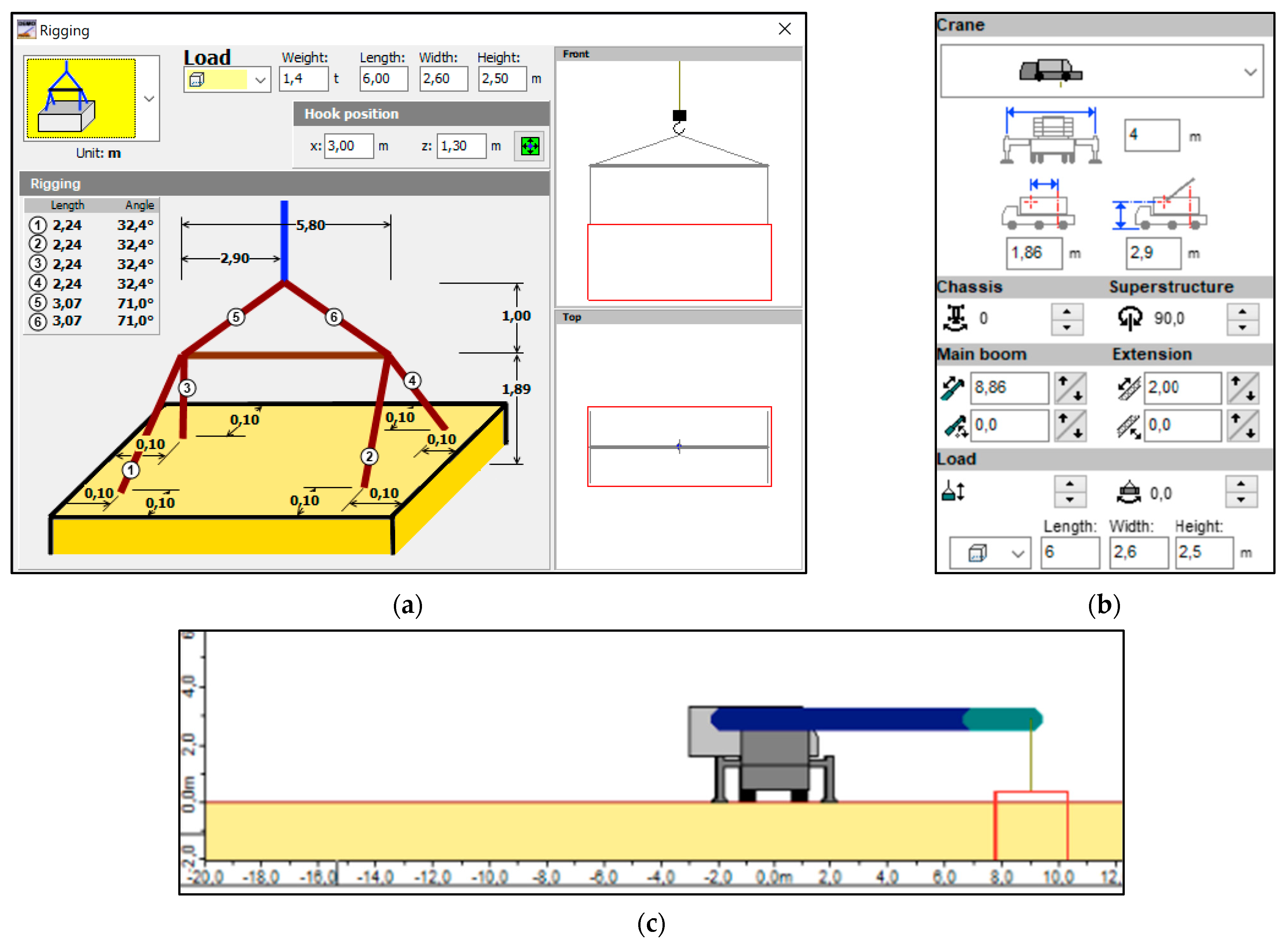
3.4. Design of the Lifting Process Considering Available Machinery

Only cranes available in the local market are considered. This equipment is priced considering rental with a minimum of 90–180 h, which does not include operator or fuel costs. For the lifting work simulation, kranXpert 1.9.9.6 demo version software is used, considering terrain conditions and interferences, and using a standard crane edited according to the characteristics of the available ones (Figure 11). Availability is pointed out for each case in Table 4. The total lifting load (below the hook) is 750 kgf.
The lifting costs, including both site cases, reach 60.93 USD/h. It is essential to mention that this value is the unit price per machine hour, which is not necessarily equal to the final rental cost of the equipment due to a minimum number of rental hours determined by the supplier. In addition to this equipment, technological alternatives exist in the world market, which are presented below:
  • Derricks: This equipment requires a large surface to install the guy-wires needed to provide stability to the machinery. Also, some of the parts usually need mechanical assistance (crane trucks or winches) to be mounted in the operational position.
  • Forklifts: This equipment is usually used in volumetric modules’ installation, but a flat transit surface is always needed. This last aspect is unusual in the projects in the scope of this research.
  • Tower Cranes: This type of equipment requires less space on the construction platform, making it possible to avoid interferences. A specially designed, dismountable tower crane should be a feasible alternative.

4. Discussion

Assessment of Economic and Environmental Cost of the Alternatives

In order to evaluate the cost and environmental impacts of the new alternative versus the traditional modularisation method, a comparison was performed to evaluate the embodied carbon and cost of the construction materials. The evaluation takes into consideration the stages of the life cycle of a building according to EN15978 [82]. The benefits of the proposed methodology are mainly in stages A1–A3 (product stage) and D (benefits and loads beyond the building life cycle) [83].
In the case of the product stage, the ETASS makes it possible to avoid using a cold-formed steel frame. The environmental impact is directly related to the production methodology of the steel, especially the proportion produced by the melting of recycled scrap steel in an electric arc furnace (EAF), which consumes less energy and emits less CO2 than other methods [84]. Considering the U.S. steel market, EAF produced a carbon footprint of 0.6 tCO2/tcs (tonnes of CO2 per tonne of crude steel) compared to the 2.1 tCO2/tcs emitted using the blast furnace and basic oxygen furnace methods (BF/BOF) [85]. However, considering the data only from the South American region, 31.9% of steel is produced by the EAF methodology [86], which produces a carbon footprint of 1.6 tCO2/tcs.
Table 5 presents a comparison between both alternatives (traditional versus proposed methodology) considering only the C100 × 100 × 3 steel frames in all the corners of each module (horizontal and vertical). According to the results, it is possible to determine that the proposed alternative is 54.39% less expensive compared with the traditional alternative. At the same time, it is possible to determine that the proposed alternative has a carbon footprint 54.44% lower than the traditional construction method. In both cases, the lower cost and environmental impacts are explained by the fact that the reusable stiffener frame allows considerable savings in material usage.

5. Conclusions and Recommendations

This paper proposes a novel construction system consisting of a supplementary structure that allows volumetric modular structures of lightweight steel to resist the efforts produced by transport and lifting processes in an offsite construction methodology. Considering the results of this research, the following conclusions can be drawn:
  • The traditional modularisation method increases the cost of social housing because the structure must be oversized. Then, the increased cost is an obstacle to the possibility of financing the modularisation of social housing in developing countries and EEs.
  • The novel offsite construction method allows the prefabrication of social housing with less direct cost compared to the traditional methodology. Consequently, savings are produced by avoiding the cold-formed steel structure of the traditional offsite construction methodologies for modules.
  • The novel offsite construction method allows the prefabrication of social housing with less environmental impact compared with the traditional methodology. It is important to highlight that the technical evaluation of both cost and environmental impact was performed according to Chilean regulations for this type of infrastructure.
  • Since offsite construction methods are in their early stages in Chile, the market for machinery and other related equipment needs to be adapted to this new type of methodology in order to allow the optimisation of cost and productivity enhancements to construction processes.
  • Since this paper is mostly focused on practitioners and scientists, policy makers are outside the scope of this research. However, we are certain that the results of this paper can be considered in public policies on social housing to encourage more affordable and environmentally friendly industrialised housing.
The significance of this research is related to the fact that it is possible to improve the construction methods for social housing in developing countries and EEs using new approaches that consider standardised local materials and traditional lifting machinery. Novel construction systems can allow for improved productivity and reduced cost and environmental impacts to overcome the high demand for social housing in EEs and developing countries. Although the results of this research are focused on Chile and two particular locations, the technical, economic, and environmental feasibility of the methodology and the proposed novel system can be evaluated in other regions and countries as well. Finally, the results of this paper can be also considered to make public policies that encourage more affordable and environmentally friendly industrialised social housing in EEs, considering social, environmental, and economic sustainability.

Author Contributions

Conceptualisation, D.T., M.G., S.V. and C.A.; research, modelling, calculation, analysis, and writing—original draft preparation and editing, D.T.; review and editing and supervision, M.G. and S.V. All authors have read and agreed to the published version of the manuscript.

Funding

The authors would like to acknowledge funding from the Pontificia Universidad Católica de Chile through their VRI Scholarships Program.

Institutional Review Board Statement

Not applicable.

Informed Consent Statement

Not applicable.

Data Availability Statement

No new data were created or analyzed in this study. Data sharing is not applicable to this article.

Acknowledgments

Danilo Tapia and Sergio Vera are thankful for the funding by the National Agency of Research and Development (ANID) of Chile under research grant ANID FONDAP 1522A0002.

Conflicts of Interest

The authors declare no conflict of interest.

References

  1. United Nations. Déficit Habitacional en América Latina y el Caribe; UN-Habitat: Nairobi, Kenya, 2015. [Google Scholar]
  2. Samarasinghe, D.A.S. The housing crisis in Australia and New Zealand: A comparative analysis through policy lenses. Int. J. Constr. Supply Chain. Manag. 2020, 10, 212–223. [Google Scholar] [CrossRef]
  3. Malpezzi, S. Housing affordability and responses during times of stress: A preliminary look during the COVID-19 pandemic. Contemp. Econ. Policy 2023, 41, 9–40. [Google Scholar] [CrossRef]
  4. Bangura, M.; Lee, C.L. The determinants of homeownership affordability in Greater Sydney: Evidence from a submarket analysis. Hous. Stud. 2023, 38, 206–232. [Google Scholar] [CrossRef]
  5. Unal, U.; Hayo, B.; Erol, I. The Effect of Immigration on the German Housing Market. SSRN Electron. J. 2023. [Google Scholar] [CrossRef]
  6. IPCC. Climate Change 2022: Impacts, Adaptation and Vulnerability. In Summary for Policymakers; Cambridge University Press: Cambridge, UK; New York, NY, USA, 2022. [Google Scholar]
  7. Naciones Unidas. La Agenda 2030 y los Objetivos de Desarrollo Sostenible Una Oportunidad Para América Latina y el Caribe Gracias Por su Interés en Esta Publicación de la CEPAL. 2018. Available online: https://repositorio.cepal.org/bitstream/handle/11362/40155/24/S1801141_es.pdf (accessed on 1 October 2021).
  8. OECD. Value Added by Activity. Total, Annual Growth Rate (%), 1990–2020. Available online: https://data.oecd.org/chart/6skv (accessed on 8 September 2021).
  9. IEA. Global Status Report for Buildings and Construction Sector 2019; IEA: Paris, France, 2019. [Google Scholar]
  10. United Nations. Country Classifications; United Nations: New York, NY, USA, 2014. [Google Scholar] [CrossRef]
  11. United Nations. Emerging Economies and the Monetary Tightening Path in the United States Development Issues No. 12; United Nations: New York, NY, USA, 2018. [Google Scholar]
  12. United Nations. World Economic Situation and Prospects as of Mid-2020; United Nations: New York, NY, USA, 2020. [Google Scholar] [CrossRef]
  13. CChC. Fundamenta 45—Gerencia de Estudios CChC El Sector de la Construcción ante el Desafío Climático Global; CCHC: Santiago, Chile, 2019. [Google Scholar]
  14. United Nations Human Settlements Programme. Tracking Progress towards Inclusive, Safe, Resilient and Sustainable Cities and Human Settlements; United Nations: New York, NY, USA, 2018. [Google Scholar]
  15. Goodier, C.; Gibb, A. Future opportunities for offsite in the UK. Constr. Manag. Econ. 2007, 25, 585–595. [Google Scholar] [CrossRef]
  16. Allen, S.G. Why Construction Industry Productivity Is Declining. Rev. Econ. Stat. 1985, 67, 661–669. [Google Scholar] [CrossRef]
  17. Dixit, S.; Mandal, S.N.; Thanikal, J.V.; Saurabh, K. Evolution of studies in construction productivity: A systematic literature review (2006–2017). Ain Shams Eng. J. 2019, 10, 555–564. [Google Scholar] [CrossRef]
  18. McKinsey & Company; M. G. Institute. Reinventing Construction: A Route To Higher Productivity; McKinsey & Company: Chicaco, IL, USA, 2017. [Google Scholar]
  19. Comisión Nacional de Productividad. Productividad en el Sector de la Construcción; Comisión Nacional de Productividad: Santiago, Chile, 2020. [Google Scholar]
  20. Tatum, C.B.; Vanegas, J.A.; Williams, J.M. Constructability Improvement Using Prefabrication, Preassembly, and Modularization; Bureau of Engineering Research, University of Texas at Austin: Austin, TX, USA, 1987. [Google Scholar]
  21. Švajlenka, J.; Kozlovská, M.; Spišáková, M. The benefits of modern method of construction based on wood in the context of sustainability. Int. J. Environ. Sci. Technol. 2017, 14, 1591–1602. [Google Scholar] [CrossRef]
  22. Zabihi, H.; Habib, F.; Mirsaeedie, L. Definitions, concepts and new directions in Industrialized Building Systems (IBS). KSCE J. Civ. Eng. 2013, 17, 1199–1205. [Google Scholar] [CrossRef]
  23. López-Guerrero, R.E.; Vera, S.; Carpio, M. A quantitative and qualitative evaluation of the sustainability of industrialised building systems: A bibliographic review and analysis of case studies. Renew. Sustain. Energy Rev. 2022, 157, 112034. [Google Scholar] [CrossRef]
  24. Baghchesaraei, O.R.; Lavasani, H.H.; Baghchesaraei, A. Behavior of Prefabricated Structures in Developed and Developing Countries. Bull. Société Sci. Liège 2016, 85, 1229–1234. [Google Scholar] [CrossRef]
  25. Banco Interamericano de Desarrollo. Un Espacio Para el Desarrollo: Los Mercados de Vivienda en América Latina y el Caribe; Estados Unidos: Washington, DC, USA, 2012. [Google Scholar] [CrossRef]
  26. Abdelmageed, S.; Zayed, T. A study of literature in modular integrated construction—Critical review and future directions. J. Clean. Prod. 2020, 277, 124044. [Google Scholar] [CrossRef]
  27. Lychgate Projects Ltd. Modern Methods of Construction: Views from the Industry. 2016. Available online: http://www.nhbcfoundation.org/Publications/Primary-Research/Modern-methods-of-construction-NF70 (accessed on 17 October 2023).
  28. Brennan, J.; Vokes, C.; CITB. Faster, Smarter, More Efficient: Building Skills for Offsite Construction. April 2017. Available online: https://www.citb.co.uk/documents/research/offsite_construction/offsite_construction_full_report_20170410.pdf (accessed on 17 October 2023).
  29. Azman, M.N.A.; Ahamad, M.S.S.; Husin, W.M.A.W. Comparative Study on Prefabrication Construction Process. Int. Surv. Res. J. 2012, 2, 45–58. [Google Scholar]
  30. Bertram, N.; Fuchs, S.; Mischke, J.; Palter, R.; Strube, G.; Woetzel, J. Modular Construction: From Projects to Products. June 2019. Available online: https://www.mckinsey.com/industries/capital-projects-and-infrastructure/our-insights/modular-construction-from-projects-to-products (accessed on 1 October 2021).
  31. Bendi, D.; Rana, M.Q.; Arif, M.; Goulding, J.S.; Sawhney, A. An off-site construction readiness maturity model for the Indian construction sector. Constr. Innov. 2020, 21, 123–142. [Google Scholar] [CrossRef]
  32. Krishnanunny, M.; Anoop, K. Prefab technology a solution to existing challenges in construction sector of India—A Kerala perspective. Int. J. Pure Appl. Math. 2018, 119, 1339–1347. [Google Scholar]
  33. Shen, K.; Cheng, C.; Li, X.; Zhang, Z. Environmental Cost-Benefit Analysis of Prefabricated Public Housing in Beijing. Sustainability 2019, 11, 207. [Google Scholar] [CrossRef]
  34. Chiang, Y.-H.; Chan, E.H.-W.; Lok, L.K.-L. Prefabrication and barriers to entry—A case study of public housing and institutional buildings in Hong Kong. Habitat Int. 2006, 30, 482–499. [Google Scholar] [CrossRef]
  35. Zhang, X.; Skitmore, M.; Peng, Y. Exploring the challenges to industrialized residential building in China. Habitat Int. 2014, 41, 176–184. [Google Scholar] [CrossRef]
  36. Hong, J.; Shen, G.Q.; Li, Z.; Zhang, B.; Zhang, W. Barriers to promoting prefabricated construction in China: A cost–benefit analysis. J. Clean. Prod. 2018, 172, 649–660. [Google Scholar] [CrossRef]
  37. Han, Y.; Wang, L. Identifying barriers to off-site construction using grey DEMATEL approach: Case of China. J. Civ. Eng. Manag. 2018, 24, 364–377. [Google Scholar] [CrossRef]
  38. Khahro, S.H.; Memon, N.A.; Ali, T.H.; Memon, Z.A. Adoption of Prefabrication in Small Scale Construction Projects. Civ. Eng. J. 2019, 5, 1099–1104. [Google Scholar] [CrossRef]
  39. Hwang, B.-G.; Shan, M.; Looi, K.-Y. Key constraints and mitigation strategies for prefabricated prefinished volumetric construction. J. Clean. Prod. 2018, 183, 183–193. [Google Scholar] [CrossRef]
  40. Masood, R.; Lim, J.B.; González, V.A. Performance of the supply chains for New Zealand prefabricated house-building. Sustain. Cities Soc. 2020, 64, 102537. [Google Scholar] [CrossRef]
  41. Bakhaty, Y.; Kaluarachchi, Y. Critical success factors, barriers and challenges for adopting offsite prefabrication: A systematic literature review. In Proceedings of the ARCOM 2020—Association of Researchers in Construction Management, 36th Annual Conference 2020—Proceedings, Online, 7–8 September 2020; pp. 366–375. [Google Scholar]
  42. Girma, S.; Chimdi, J.; Mosisa, A. Challenges of Using Prefabrication Technology in Oromia Regional State. J. Civ. Eng. Sci. Technol. 2020, 11, 22–270. [Google Scholar] [CrossRef]
  43. Ortega, J.; Mesa, H.A.; Alarcón, L.F. The interrelationship between barriers impeding the adoption of off-site construction in developing countries: The case of Chile. J. Build. Eng. 2023, 73, 106824. [Google Scholar] [CrossRef]
  44. Wuni, I.Y.; Shen, G.Q. Barriers to the adoption of modular integrated construction: Systematic review and meta-analysis, integrated conceptual framework, and strategies. J. Clean. Prod. 2020, 249, 119347. [Google Scholar] [CrossRef]
  45. Alinaitwe, H.M.; Mwakali, J.; Hansson, B. Assessing the degree of industrialisation in construction—A case of Uganda. J. Civ. Eng. Manag. 2006, 12, 221–229. [Google Scholar] [CrossRef]
  46. Torres, J.; Torres, A. El Contexto Económico, Social y Tecnológico de la Producción de Vivienda Social en América Latina; Encuentro Latinoamericano de Gestión y Economía de la Construcción: Bogotá, Colombia, 2009. [Google Scholar]
  47. Kempton, J.; Fergusson, S. Potential of Prefabricated Pods to Extend Houses: Initial Feasibility Study for Social Housing. In Proceedings of the 20th Annual ARCOM Conference, Edinburgh, UK, 1–3 September 2004; Khosrowshahi, F., Ed.; Volume 1, pp. 223–232. [Google Scholar]
  48. Alvarado, A. Construcción Industrializada Para la Vivienda Social en Chile: Análisis De Su Impacto Potencial. Ciclo de Seminarios Académicos de Economía. 2010. p. 44. Available online: https://s3.amazonaws.com/academia.edu.documents/38703170/Paper-Vivienda-Industrializada-AAD-Oct2010-.pdf?AWSAccessKeyId=AKIAIWOWYYGZ2Y53UL3A&Expires=1537056744&Signature=RrOTK6u5wlz7UxEYTW1YUjLdQ3c%3D&response-content-disposition=inline%3Bfilename%3DVivi (accessed on 17 October 2023).
  49. Building and Construction Authority. Design for Manufacturing and Assembly (DFMA); Building and Construction Authority: Singapore, 2009.
  50. López, J.J.; López, C. El Urbanismo de ladera: Un reto ambiental, tecnológico y del ordenamiento territorial. Bitácora Urbano Territ. 2004, 1, 94–102. [Google Scholar]
  51. Velamati, S. Feasibility, Benefits and Challenges of Modular Construction in High Rise Development in the United States: A Developer’s Perspective; Massachusetts Institute of Technology: Cambridge, MA, USA, 2012. [Google Scholar]
  52. O’connor, J.T.; O’brien, W.J.; Choi, J.O. Industrial Project Execution Planning: Modularization versus Stick-Built. Pr. Period. Struct. Des. Constr. 2016, 21, 04015014. [Google Scholar] [CrossRef]
  53. Lopes, G.C.; Vicente, R.; Azenha, M.; Ferreira, T.M. A systematic review of Prefabricated Enclosure Wall Panel Systems: Focus on technology driven for performance requirements. Sustain. Cities Soc. 2018, 40, 688–703. [Google Scholar] [CrossRef]
  54. Lizana-Moral, F.J.; Jiménez, A.J.S.; Such, A.V.; Padura, Á.B.; Huelva, M.M. Análisis de ciclo de vida y prefabricación. Evaluación del desempeño ambiental de diferentes sistemas industrializados en la edificación. In II Congreso Internacional y IV Nacional de Construcción Sostenible y Soluciones Eco-Eficientes; Depósito de Investigación Universidad de Sevilla: Sevilla, Spain, 2015; pp. 1020–1033. [Google Scholar]
  55. Jaillon, L.; Poon, C.S. Sustainable construction aspects of using prefabrication in dense urban environment: A Hong Kong case study. Constr. Manag. Econ. 2008, 26, 953–966. [Google Scholar] [CrossRef]
  56. Salama, T.; Salah, A.; Moselhi, O.; Al-Hussein, M. Near optimum selection of module configuration for efficient modular construction. Autom. Constr. 2017, 83, 316–329. [Google Scholar] [CrossRef]
  57. Smith, R.E. Prefab Architecture: A Guide to Modular Design and Construction; John Wiley & Sons, Inc.: Hobobken, NJ, USA, 2011. [Google Scholar]
  58. Lacey, A.W.; Chen, W.; Hao, H.; Bi, K. Structural response of modular buildings—An overview. J. Build. Eng. 2018, 16, 45–56. [Google Scholar] [CrossRef]
  59. Innella, F.; Bai, Y.; Zhu, Z. Mechanical performance of building modules during road transportation. Eng. Struct. 2020, 223, 111185. [Google Scholar] [CrossRef]
  60. Asiz, A.; Smith, I. Lifting and Transportation Forces in Prefabricated Units Field Test. In Proceedings of the World Conference on Timber Engineering, Portland, OR, USA, 6–10 August 2006. [Google Scholar]
  61. Valinejadshoubi, M.; Bagchi, A.; Moselhi, O. Damage detection for prefabricated building modules during transportation. Autom. Constr. 2022, 142, 04018031. [Google Scholar] [CrossRef]
  62. Innella, F.; Luo, F.J.; Bai, Y. Capacity of Screw Connections between Plasterboard Panels and Cold-Formed Steel for Modular Buildings. J. Archit. Eng. 2018, 24, 04018031. [Google Scholar] [CrossRef]
  63. Bruen, J.; Hadjri, K.; von Meding, J. Design Drivers for Affordable and Sustainable Housing in Developing Countries. J. Civ. Eng. Arch. 2013, 7, 1220–1228. [Google Scholar]
  64. Ganiyu, B.; Fopohunda, J.; Haldenwng, R. Construction Approaches to Enhance Sustainability in Affordable Housing in Developing Countries. In Proceedings of the 2015 World Congress on Sustainable Technologies (WCST), London, UK, 14–16 December 2015. [Google Scholar]
  65. Servicio de Vivienda y Urbanización V Región. Licitación ID: 704093-153-LR20 LP 124-2020 CONSTRUCCIÓN VIVIENDAS LIMACHE. Available online: https://www.mercadopublico.cl/Procurement/Modules/RFB/DetailsAcquisition.aspx?qs=o7TQSQtm1T/1zWs8BJjyXw== (accessed on 1 October 2021).
  66. CSI. SAP2000 Integrated Software for Structural Analysis and Design; Computers and Structures Inc.: Berkley, CA, USA, 2021. [Google Scholar]
  67. Scholl, M. Kranxpert Demo Version; Informer Technologies: Altenkunstadt, Germany, 2021. [Google Scholar]
  68. Ministerio de Vivienda y Urbanismo. Programa Habitacional Fondo Solidario de Elección de Vivienda; Ministerio de Vivienda y Urbanismo: Santiago, Chile, 2011.
  69. Ministerio de Vivienda y Urbanismo. Itemizado Tecnico de Construccion Para Proyectos del Fondo Solidario de Eleccion de Vivienda; Ministerio de Vivienda y Urbanismo: Santiago, Chile, 2012.
  70. Ministerio de Vivienda y Urbanismo. Cuadro Normativo y Tabla de Espacios y Usos Minimos Para el Mobiliario; Ministerio de Vivienda y Urbanismo: Santiago, Chile, 2017.
  71. Ministerio de Vivienda y Urbanismo. Ordenanza General de Urbanismo y Construcciones; Ministerio de Vivienda y Urbanismo: Santiago, Chile, 2017.
  72. Ministerio de Transportes y Telecomunicaciones. Resolucion No 1 de 1995 del Ministerio de Transportes y Telecomunicaciones. In Establece Dimensiones Maximas a Vehiculos; Ministerio de Transportes y Telecomunicaciones: Santiago, Chile, 1995; pp. 1–3. [Google Scholar]
  73. NSEG 5. E.n.71; Reglamento de Instalaciones Electricas de Corrientes Fuertes. Superintendencia de Electricidad y Combustibles: Santiago, Chile, 1971.
  74. Subsecretaria de Telecomunicaciones. Cableado. Available online: https://www.subtel.gob.cl/cableado/ (accessed on 25 May 2021).
  75. National Modular Housing Council. Builder’s Guide to Modular Home Set-Up & Completion. Available online: https://www.manufacturedhousing.org/wp-content/uploads/2017/01/Builders-Guide-to-Modular-Home-Set-Up-Completion.pdf (accessed on 17 October 2023).
  76. Corporacion de Desarrollo Tecnológico. La Plataforma Online de Apoyo a la Especificacion Tecnica. Available online: http://www.especificar.cl/ (accessed on 27 May 2021).
  77. The Modular Building Institute. Bathroom Pods; The Modular Building Institute: Charlottesville, VA, USA, 2017. [Google Scholar]
  78. Instituto Nacional de Normalizacion. Diseño Sísmico de Edificios; Instituto Nacional de Normalizacion: Santiago, Chile, 2009. [Google Scholar]
  79. Godbole, S.; Lam, N.; Mafas, M.; Fernando, S.; Gad, E.; Hashemi, J. Dynamic loading on a prefabricated modular unit of a building during road transportation. J. Build. Eng. 2018, 18, 260–269. [Google Scholar] [CrossRef]
  80. Instituto de Nacional de Normalizacion. Diseño Estructural—Cargas De Viento; Instituto de Nacional de Normalizacion: Santiago, Chile, 2010. [Google Scholar]
  81. Ministerio de Vivienda y Urbanismo. Manual de Obras de Vialidad, Pavimentación y Aguas Lluvias; Ministerio de Vivienda y Urbanismo: Santiago, Chile, 2020; Volume 2, pp. 1–46.
  82. EN 15978: 2011; BS EN 15978:2011—Sustainability of Construction Works—Assessment of Environmental Performance of Buildings—Calculation Method. iTeh Standards: Newark, DE, USA, 2011.
  83. EN 15978: 2011; BRE Global Methodology for the Environmental Assessment of Buildings Using. BRE Global: London, UK, 2018.
  84. Lin, Y.; Yang, H.; Ma, L.; Li, Z.; Ni, W. Low-Carbon Development for the Iron and Steel Industry in China and the World: Status Quo, Future Vision, and Key Actions. Sustainability 2021, 13, 12548. [Google Scholar] [CrossRef]
  85. Zhang, Q.; Xu, J.; Wang, Y.; Hasanbeigi, A.; Zhang, W.; Lu, H.; Arens, M. Comprehensive assessment of energy conservation and CO2 emissions mitigation in China’s iron and steel industry based on dynamic material flows. Appl. Energy 2018, 209, 251–265. [Google Scholar] [CrossRef]
  86. World Steel Association. Steel Statistical Yearbook 2020 Extended Version; World Steel Association: Brussels, Belgium, 2020. [Google Scholar]
Figure 1. Research methodology.
Sustainability 15 16922 g001
Figure 2. Study cases. (a) Case 1: distances: horizontal: 18.5 m; vertical: −5.3 m. (b,c) Case 2: distances: horizontal: 9 m; vertical: −3 m (distances measured from the road axis).
Sustainability 15 16922 g002
Figure 3. Study cases. Case 1: distances: horizontal: 18.5 m; vertical: −5.3 m (left house) and Case 2: distances: horizontal: 9 m; vertical: −3 m (right house) (distances measured from the road axis).
Sustainability 15 16922 g003
Figure 4. (a) Original architectural blueprints, (b) proposed modularisation, and (c) resultant modules.
Sustainability 15 16922 g004
Figure 5. (a) Elevation view of ETASS (in green) during assembly, (b) ETASS finishing assembly, (c) final structure after assembly, and (d) finished house.
Sustainability 15 16922 g005
Figure 6. (a,b) 3D view of the ETASS. (c) Top detail of structure coupled with the module.
Sustainability 15 16922 g006
Figure 7. Bottom detail of secondary structure.
Sustainability 15 16922 g007
Figure 8. (a) Detail of bottom connection between module and secondary structure. (b) Detail of bottom connection after installation of the module.
Sustainability 15 16922 g008
Figure 9. Displacement simulation of the secondary structure under load combinations. (a) Combo 5 (lifting). (b) Combo 2. (c) Combo 3 (transport).
Sustainability 15 16922 g009
Figure 10. Proposed lifting arrangement.
Sustainability 15 16922 g010
Figure 11. Lifting simulation using kranXpert. (a) Rigging arrangement. (b) Input board. (c) 2D view.
Sustainability 15 16922 g011
Table 1. Weight estimation of each module.
Weight Calculation—Module M-1
ElementDescriptionUnitary WeightUnitQty.LongitudeTotal Weight [kg]
StudsC 2 × 3 × 0.850.8mL14.02.426.9
Sole plateU 2 × 3 × 0.850.7mL9.02.415.1
Top plateU 2 × 3 × 0.850.7mL9.02.415.1
Interior finishesPlasterboard 15 mm12.0m221.7 260.4
Condensation barrier0.1m221.7 2.2
Exterior finishesAsphalt paper 10/400.2m210.8 2.2
OSB 9.5 mm7.1m210.8 76.7
PVC Siding1.6m210.8 17.3
ElectricityConduit plug 1/2″0.2mL1.03.00.6
Conduit lighting 1/2″0.2mL1.05.01.0
Conduit switch 1/2″0.2mL1.02.00.4
Wires 1.5 mm0.12mL3.010.03.6
DoorDoor11.8uni1.0 11.8
ScrewsScrews (all types used
in Drywall system)
7.5gL1.0 7.5
WindowWidow 100 × 100 × 3 mm8.4uni1.0 8.4
Total weight [kg]449.2
Table 2. Load combinations and multipliers included in the FEM model.
CombinationsLoad Multipliers
ComboDead (Self-Weight)Dead (Module Weight)W (Wind)S (Slings)
Case 1: TransportCombo 11 (Gravity direction)1 (Gravity direction)1 (X direction)0
Combo 2−4.3 (Gravity direction)−4.3 (Gravity direction)1 (X direction)0
Combo 34.3 (Gravity direction)4.3 (Gravity direction)1 (X direction)0
Combo 41 (12% deviation)1 (12% deviation)1 (X direction)0
Case 2: LiftingCombo 51 (Gravity direction)1 (Gravity direction)01 (X and −X)
Table 3. Maximum and minimum displacements of ETASS in the superior and inferior supports of the panels. The bold numbers are the maximum and minimum displacements for each combination.
Joint Displacements
CASEJointOutputCaseCaseTypeU1U2U3R1R2R3
TextTextTextTextmmmRadiansRadiansRadians
178Combo 1Combination−3.899 × 10⁻⁶−6.342 × 10⁻⁶−0.000151−0.000116−0.000078−0.000047
170Combo 1Combination−3.204 × 10−60.000012−0.0001420.0001240.0001890.000031
174Combo 1Combination−0.0001383.734 × 10−6−0.0002986.904 × 10−60.002846−0.000013
155Combo 1Combination0.000076−3.459 × 10−60.000127−0.0000290.002372−0.000012
178Combo 2LinStatic0.000061−9.285 × 10⁻⁶−0.000138−0.000125−0.002279−0.000062
170Combo 2LinStatic0.0000410.000015−0.0001280.000138−0.0020130.000024
173Combo 2LinStatic0.000221−2.89 × 10⁻⁶−0.0004292.047 × 10−60.0031171.328 × 10−6
151Combo 2LinStatic0000.0000130.0018095.663 × 10−6
178Combo 3LinStatic0.000061−9.285 × 10⁻⁶−0.000138−0.000125−0.002279−0.000062
170Combo 3LinStatic0.0000410.000015−0.0001280.000138−0.0020130.000024
173Combo 3LinStatic0.000221−2.89 × 10⁻⁶−0.0004292.047 × 10−60.0031171.328 × 10−6
151Combo 3LinStatic0000.0000130.0018095.663 × 10−6
178Combo 4LinStatic0.000061−0.000014−0.000125−0.000136−0.001905−0.000028
170COMBO 4LinStatic0.000040.000014−0.0001280.000136−0.0020130.000024
173COMBO 4LinStatic0.000213−3.115 × 10⁻⁸−0.000421−3.173 × 10−70.003081−8.588 × 10⁻⁷
151COMBO 4LinStatic0000.0000160.0018118.431 × 10−7
252COMBO 5Combination−0.000353−0.000034−0.0000270.0001040.0011920.000186
274COMBO 5Combination−0.0005420.000035−0.0002130.000024−0.0002530.000114
21COMBO 5Combination−0.0006080.000033−0.00029−0.000997−0.0027130.000239
256COMBO 5Combination000−0.00030.000202−4.024 × 10⁻⁶
Table 4. Available lift equipment and specifications.
TypeCrane ModelMax. Working Radius [m]Working Range (Height) [m]Max. Width with Stabilisation at 100% Extension [m]Cost [USD/h]Case 1Case 2
Spider URW 37614.45−77.07–14.454.44 43.48
Spider URW 50615.71−86.57–15.715.9448.54
Spider URW 2958.41−46.8–8.413.93541.02
Truck HIAB XS 28812.6853–12.69 45.13
Truck PM 3214.850.9–418.45.46560.89
Truck PM 165239.951.240–13.194.735.71
Truck ATLAS 3323E A516.494–18.3660.89
Truck ATLAS AK1652EA312.25−8–12.84.03035.72
Table 5. Summary of economic and environmental comparison of both alternatives, considering one housing unit.
Traditional OSCProposed OSCSavings
Steel [kg]225410281226
Cost [USD]15,26069598300
Embodied carbon [tCO2]3.601.641.96
Disclaimer/Publisher’s Note: The statements, opinions and data contained in all publications are solely those of the individual author(s) and contributor(s) and not of MDPI and/or the editor(s). MDPI and/or the editor(s) disclaim responsibility for any injury to people or property resulting from any ideas, methods, instructions or products referred to in the content.

