Article

Fault Detection in a Single-Bus DC Microgrid Connected to EV/PV Systems and Hybrid Energy Storage Using the DMD-IF Method

by
Alireza Sistani
1,
Seyed Amir Hosseini
1,*,
Vahideh Sadat Sadeghi
1 and
Behrooz Taheri
2
1
Electrical and Computer Engineering Group, Golpayegan College of Engineering, Isfahan University of Technology, Golpayegan 8771767498, Iran
2
Department of Electrical Engineering, Qazvin Branch, Islamic Azad University, Qazvin 341851416, Iran
*
Author to whom correspondence should be addressed.
Sustainability 2023, 15(23), 16269; https://doi.org/10.3390/su152316269
Submission received: 10 October 2023 / Revised: 15 November 2023 / Accepted: 22 November 2023 / Published: 24 November 2023

Abstract

:
Variations in fault currents, short times to clear the fault, and a lack of a natural current zero-crossing point are the most important challenges that DC microgrid protection faces. This challenge becomes more complicated with the presence of electric vehicles and energy storage systems due to their uncertainties. For this reason, in this paper, a new method for fault detection in DC microgrids with the presence of electric vehicles and energy storage systems is proposed. The new proposed method uses the combination of dynamic mode decomposition and instantaneous frequency for fault detection. In this method, first, a reference signal is made using the voltage and current signal sampled from the DC microgrid using the dynamic mode decomposition method. Next, in order to detect the fault, the instantaneous frequency value of the reference signal is calculated by the Hilbert transform. The simultaneous use of voltage and current signals reduces the transient effects of the control system on the proposed protection method. In order to measure voltage and current signals, only one intelligent electronic device unit is used in this paper. The proposed new method has been tested on a single-bus DC microgrid with the presence of electric vehicles and energy storage systems in MATLAB 2019b software. The results show that this method can detect all types of faults in DC microgrids, electric vehicles, and photovoltaics. Also, this method is immune to the uncertainties of the generation of distributed generation resources and the existence of noise distortions in the measured signals.

1. Introduction

Significant advances in the field of power electronics, the ever-increasing electrical loads, as well as concerns about environmental problems have led to the increased use of distributed generation (DG) resources [1,2,3]. For this reason, the belief has been created among researchers in the field of energy that microgrids are one of the suitable options for solving these problems. A microgrid is a distribution network that includes DGs, loads, and energy storage systems [1].
Microgrids are divided into two types, AC and DC [4]. Today, the use of DC microgrids has increased due to the use of more DC loads and the fact that DC is the nature of most DGs [5,6]. DC microgrids have advantages such as a high efficiency [7], the easy connection of different resources through electronic power converters [8], and the ability to supply electricity to ships, remote areas from the power grids, and sensitive electronic equipment [9].
One of the most important challenges of DC microgrids is designing a suitable protection system for these networks [10]. Actually, the main challenges of protecting DC microgrids can be seen as the change in the short circuit level, the high rate of changes in the fault current, the very short time to detect and clear the fault, the high uncertainty of DGs, and the lack of a natural zero current crossing point [11,12]. In addition, the effect of low line impedance and fault resistance may make fault detection in DC microgrids a challenge [10]. The high amplitude of the DC fault current may damage the converters [13,14]. Another challenging issue that may make fault detection in DC microgrids difficult is the effect of noise on the sampled signals [15]. In addition, the uncertainty of the generation of DGs and transient states in the network, including the connecting/disconnecting of loads, may make fault detection a challenge [16]. Therefore, fault detection in the shortest time in order to prevent damage to the equipment in the network is very important in protecting a microgrid. In order to solve the challenges raised, many studies have been conducted in this field in recent years. In general, these studies are divided into two categories; local computing and that based on communications [17].
The most common scheme for fault detection in DC microgrids is differential protection [18]. This method calculates the difference between the currents on both sides of the protection zone, and if this difference is greater than the threshold, it issues a trip command [19]. The reason for using the threshold value in differential protection is to separate and distinguish the fault state from the normal state [20]. Synchronizing the sampled signals and then comparing them with each other in order to issue a trip command in a certain time interval is one of the challenges of this method [21]. Similarly, fault detection has been carried out in [22] using the differential method. However, it has not taken into account the generation uncertainties of DGs and the presence of energy storage systems. A scheme based on master–slave in DC microgrids has been presented in [23]. Therefore, the current status on both sides of the protection area is checked by the slaves and the information is provided to the master. Then, the master detects the fault by receiving the information sent by the slave using the differential method. Overcurrent relays have been used in [24,25] to detect pole-to-ground (PG) and pole-to-pole (PP) faults. Overcurrent protection works by dividing the microgrid into several different areas and then placing the corresponding relays at the beginning and end of each line [26]. Other conventional methods such as traveling waves, which are mostly used in AC networks, are likely to have incorrect performance in fault detection due to the lack of phasor signals in DC microgrids [27]. In [28], traveling waves are used for fault detection. However, the noise caused by the switching of the converters may affect the optimal performance of this method [29]. The use of transient waves for fault detection has also been suggested in some other studies. Therefore, the proposed method in [30] used a probabilistic neural-network to distinguish between transient states caused by faults and states caused by switching. The proposed algorithm in [28] is very sensitive to noise and may cause incorrect performances in normal network conditions. In [31], the signal processing method is used. In this method, the current of all lines in the microgrid is measured. These values are compared to the value of normal network conditions. The fault is detected by obtaining the energy of the point of the grid whose current has changed the most. What challenges the proposed method in [31] is not paying attention to the uncertainties in DG generations and not considering the effect of noise on the measured signals. The protection method presented in [32,33] is based on adaptive protection and communication between relays and protection units. In this method, all DGs and relays are connected to the central protection unit with communication channels. In this case, the status of each DG (active or inactive) is determined at any moment. According to the state of the microgrid, the central protection unit applies the settings related to each state to the relays using communication channels. In [34], the adaptive protection method is used to protect the DC microgrid. The challenge facing adaptive protection is not considering the uncertainties of communication links. The uncertainties of communication links can reduce the reliability of DC microgrid protection [16]. In [35], in order to detect the fault, the parameter estimation method is used. This method samples the voltage and current signals of microgrid lines using several intelligent electronic devices (IEDs). The proposed method in [35] does not consider the uncertainties of communication links. The impedance estimation method is proposed in [36] in order to detect faults in the DC microgrids. However, the effect of noise on the sampled signals is not considered. Another method that has been used in fault detection in DC microgrids is the use of artificial intelligence. As an example, a method based on artificial intelligence for fault detection is proposed in [37,38]. This method has used local data, although not considering transient states may challenge the proposed method. Another common method for fault detection in DC microgrids is the distance protection method. This method calculates the impedance of the lines by measuring the voltage and current of the microgrid lines. In this method, in order to detect the fault, the calculated impedance is compared with the predetermined threshold value. However, due to the large changes in voltage and current during the fault occurrence, it may cause limitations in this protection method [21,39].
As is known, the main obstacle to the expansion of DC microgrids is the existence of protection problems in this type of grid. Most of the existing methods use the current signal for fault detection or, like differential methods, need to create high-speed communication links for fault detection [40]. The use of the current signal alone can reduce the accuracy of the protection systems or improper performance during the creation of various transients, especially the transients created by the control system [
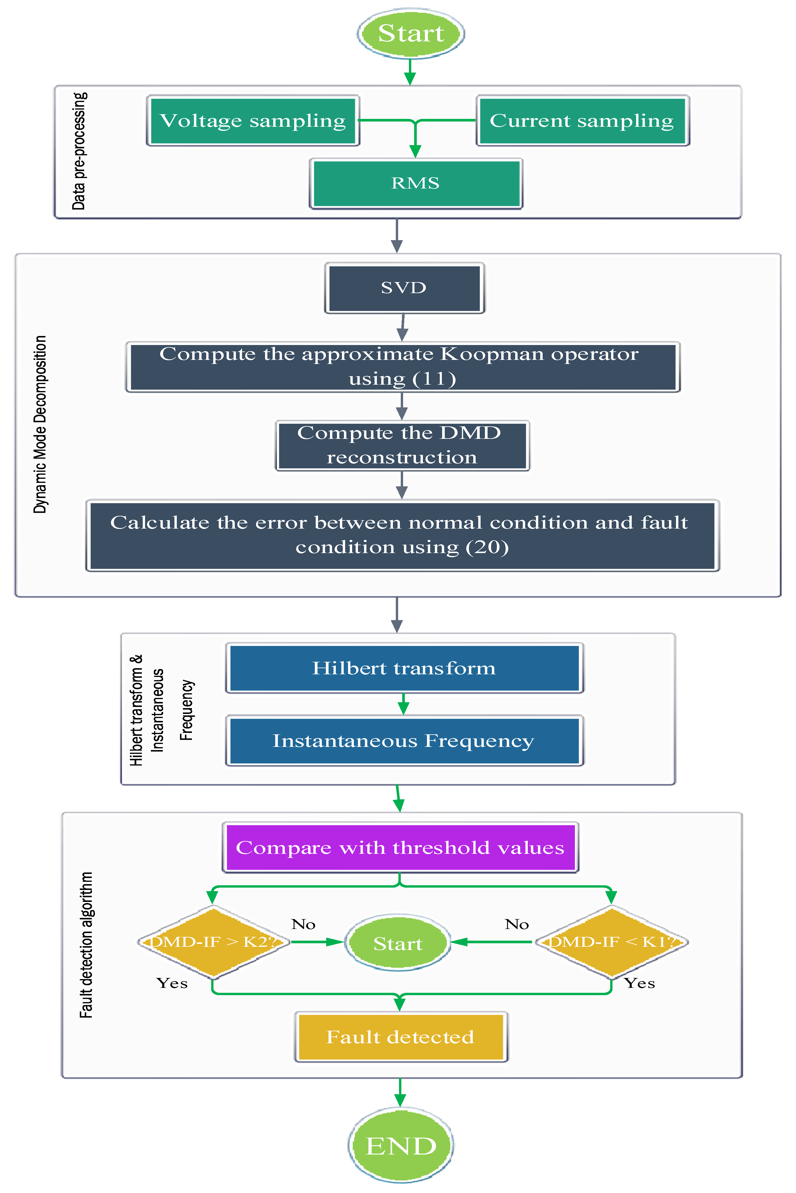
41]. Using methods with communication links or multiple IEDs to protect a DC microgrid, although solving this problem, will increase the operating cost of DC microgrids, which is one of the most important obstacles in the expansion of DC microgrids. For this reason, a combined method based on dynamic mode decomposition (DMD) and instantaneous frequency (IF) is proposed in this paper. In this method, first, a reference signal is made using the voltage and current signal sampled from the DC microgrid using DMD. The simultaneous use of voltage and current signals reduces the transient effects of the control system on the proposed protection method. Next, in order to detect the fault, the IF value of the reference signal is calculated by the Hilbert transform, and the fault is detected by determining a threshold value. It should be noted that the proposed method uses only one IED in order to detect faults in different parts of the microgrid. Using only one IED reduces the costs of building and operating the DC microgrid. The proposed new method is evaluated using a DC microgrid in MATLAB/Simulink 2019b software. The results of the investigations show that this method was able to detect all types of faults with different impedances with only one IED in a reasonable time. Also, the proposed method is not sensitive to noise and shows good performance even when the signal is noisy. Finally, the results of the comparison between the proposed new method and the existing methods of fault detection in DC microgrids show the improvement of the performance of this method in different conditions, including fault detection in different points of the DC microgrid, the correct performance in the noise of sampled signals, and changes in fault impedance.
This paper is divided as follows: In the second part, the relationships related to the proposed DMD-IF method are presented. In the third part, the sample network is introduced and the simulation results are presented. In the fourth part, a comparison between the method presented in this paper and the existing DC microgrid protection methods is examined.

2. Fault Detection Strategy

2.1. The Proposed Fault Detection Algorithm

The main goal of this paper is to detect faults in DC microgrids using a combination of DMD and IF methods in order to reduce the effects of DC microgrid control systems on protection systems. The DMD method is a popular method for modal decomposition, flow analysis, and reduced-order modeling. Also, the DMD method is widely used in the studies of dynamic systems (various studies in the fields of mechanics or power systems) [42]. This method is very suitable for revealing spatial-temporal features [43]. However, the use of DMD alone for fault detection can make it difficult to detect faults or even maloperation when creating various transients in the microgrid. For this reason, the IF value of the reconstructed signal by DMD will also be calculated in the next step.
In this study, the proposed method is based on the analysis of both current and voltage signals sampled from the DC microgrid. To obtain the reconstructed signal by the DMD, it is necessary to first sample the voltage and current of the DC microgrid in the normal (fault-free) working mode. These samples are stored inside the IED installed in the DC bus of the microgrid to be used in different conditions to generate the reconstructed signal. In the next step, during the operation time of the microgrid, the IED constantly samples the voltage and current signals of the microgrid, and a new signal is created using the new samples and the previous samples that were measured under the normal operation conditions of the microgrid. Figure 1 and Figure 2 show the signals sampled during the normal operation of the network and the time of fault occurrence in the DC microgrid, respectively. It should be noted that the oscillations created in these figures are due to the non-ideal modeling of AC/DC and DC/DC converters.
In the next step, it is necessary to take RMS from the sampled signals. Then, the sampled signals are formed in the form of matrices presented in Equations (1)–(3) [44,45].
X = [ | | | x 1 x 2 x m | | | ] n × m
X 1 = [ | | | x 1 x 2 x m 1 | | | ]
X 2 = [ | | | x 2 x 3 x m | | | ]
where X is the input data matrix, whose columns are sampled with different numbers of data. Also, X 1 and X 2 are the matrices constructed from the input matrix. It should be noted that X 2 is a time-shifted matrix [45].
Next, to reduce the complexity of the problem, the dimensions of the problem (order of data) need to be reduced by the single value decomposition method. Therefore, the decomposition of the single value of the matrix X 1 is shown in Equation (4) [44].
X 1 = U S V
where U and V are unit matrices and S is a diagonal matrix of single data. Therefore, the low-order matrices of the matrices presented in Equations (1)–(3) are obtained by using Equations (5)–(7) [45].
U r = U ( 1 : n , 1 : r )
S r = S ( 1 : r , 1 : r )
V r = V ( 1 : m , 1 : r )
where r is the order of reduction. It should be noted that in this paper, the value of r is considered equal to 1.
In the following, in order to obtain the eigenvalues, Koopman’s approximation operator has been used [45].
U r B X 1 = U r X 2
U r B ( U r S r V r ) = U r X 2
U r B U r = U r X 2 V r S r 1
B ~ = U r X 2 V r S r 1
where B ~ is the low-order approximation of the system matrix. Using this matrix and based on Equation (12), eigenvalues and eigenvectors are obtained [44].
B ~ W = W Λ
where Λ and W are the eigenvalue and eigenvector, respectively.
Based on this, the eigenvector matrix is displayed in Equation (13). Also, Equation (14) shows the eigenvalue matrix, which is a diagonal matrix [44,45].
W = [ | | | W 1 W 2 W r | | | ]
Λ = [ λ 1 0 0 0 λ 2 0 0 0 λ r ]
The modes obtained from DMD correspond to the eigenvector. For this purpose, the order of these modes is calculated from Equation (15). Also, Equation (16) shows the matrix of these modes [44].
Φ = X 2 V r S r 1 W
Φ = [ | |   | Φ 1 Φ 2 Φ r | |   | ]
where Φ k     k = 1 ,   ,   r is the eigenvalue vector, which is sometimes called the exact mode of DMD [44].
A circle with the radius 2 π is used in order to detect disturbance conditions. For this purpose, if the eigenvalue is placed inside this circle (Figure 3), it means that the network is in normal mode. On the other hand, if the obtained eigenvalue is outside the mentioned circle (Figure 4), it indicates the occurrence of disturbance in the network.
In the next step, in order to detect the fault in the DC microgrid, it is necessary to reconstruct the sampled signals in the normal state and in the fault condition. To obtain the reconstructed matrix, a coefficient is needed that shows the internal conditions of the input matrix. This coefficient is calculated based on the eigenvalue vector presented in Equation (17).
b = Φ \ X 1
where b is the decomposition coefficient of the dynamic mode and indicates the internal conditions of the X 1 matrix. In the next step, to create the reconstructed signal based on voltage and current, the dynamic time ( v ) is calculated according to what is presented in Equation (18) [43,45].
v ( t ) = b j e λ j t
where j is the mode index and v is called dynamic time.
Finally, using the discrete Fourier transform presented in Equation (19), the reconstructed matrix is obtained. Figure 5 shows the reconstructed signal by DMD in normal network conditions and in fault conditions [44,45].
X D M D = j = 1 r Φ j v j ( t )
The data sampled in normal network conditions as well as in the conditions when a fault occurred in the network have been individually reconstructed by DMD. Then, the values obtained from both modes have been converted into a signal according to Equation (20).
Residual = | X D M D _ N o r m a l X D M D _ F a u l t |
where X D M D _ N o r m a l is the reconstructed signal in the normal conditions of the microgrid Also, X D M D _ F a u l t is the reconstructed signal by DMD when the fault occurred in the microgrid.
As stated at the beginning of this section, in order to detect the fault in the DC microgrid, it is necessary to calculate the IF value of the reconstructed signal by the DMD. For this purpose, an algorithm based on the Hilbert transform has been used to calculate IF. The Hilbert transform for continuous data can be calculated through Equation (21) [46].
H [ X ( t ) ] = x ˜ ( t ) = π 1 + x ( τ ) t τ d τ
Equation (21) is suitable for use in continuous data. To use the Hilbert transform for discrete data, the algorithm presented in [46] should be used. In this algorithm, discrete data are first transferred to the domain and frequency space with the help of the fast Fourier transform. To achieve the Hilbert transform, this step involves multiplying by a homogeneous function with a vertical constant value. Finally, in order to return to the domain and time mode, the inverse function of the Fourier transform is used. After applying the Hilbert transform to the instantaneous frequency signal, it can be calculated from Equation (22) [46].
I F = F S 2 π × d i f f ( a n g l e ( X ¯ ( t ) ) )
where F S is the sampling frequency and is considered 10 kHz in this paper.
Finally, the output obtained from DMD-IF is compared with the threshold values. If the obtained DMD-IF value exceeds the threshold values, a fault is detected. Based on this, the fault detection condition can be expressed based on Equation (23).
i f ( DMD - IF > k 1   or   DMD - IF < k 2 ) = > Fault   Detect
In general, the algorithm of the proposed method is shown in Figure 6. Basically, the proposed method starts from the sampling voltage and current signals. In the next step, by reducing the rank of the matrices through SVD, the problem has been improved, and its solution has become easier. Then, by calculating the eigenmodes of DMD, a single signal is reconstructed from the voltage and current. Finally, in order to detect the fault in the microgrid, the reconstructed signal has been evaluated using the Hilbert transform and instantaneous frequency. Thus, if the calculated value is greater than one of the predetermined threshold values, a fault will be detected.

2.2. Calculation of Threshold Values

The proposed method for fault detection in the DC microgrid requires the proper determination of threshold values. These threshold values are obtained by performing different numerical simulations based on the method described in [47].
As shown in Figure 7a,b, when the fault occurs in EV and PV sources, the currents produced by these sources flow towards the fault. As a result, the current direction at the location where the current and voltage signal is sampled (IED) is reduced. Meanwhile, according to Figure 7c, when a fault occurs in the DC bus, the current and voltage increase due to the presence of DG resources in the network that cause all microgrid currents to move towards the fault location. For this purpose, and to protect the DC microgrid with only one IED, it is necessary to use two threshold values ( k 1 and k 2 ) for fault detection.
In order to calculate the values of k 1 and k 2 , the effect of noise, generation uncertainties, and the effects of the control system should also be considered. For this purpose, different types of faults are simulated according to Table 1. Next, according to the algorithm presented in Figure 8, DMD-IF values will be calculated for all situations. Finally, the measured values were compared with each other, and the lowest and highest DMD-IF values obtained from all the study cases presented in Table 1 were selected. Considering a tolerance, the threshold values in this paper are determined as k 1 = 2.70 and k 2 = 3.90 , respectively.

3. Simulation Results

3.1. Sample Network

The structure of the sample DC microgrid is shown in Figure 9. The presented DC microgrid includes EV/PV systems and hybrid energy storage systems including batteries and flywheels. In order to consider the various uncertainties and effects of the control system, the hierarchical control system presented in [48] has been fully implemented. In addition, the sample microgrid shown in Figure 9 has AC/DC and DC/DC converters and AC and DC loads. Also, this microgrid has the ability to connect to the network (grid-connected mode) through the SW switch.
The sample microgrid is a two-wire DC system that includes four lines (L1–L4). The cross-section of each line is a 240 mm2 aluminum cable with PVC insulation type A and PVC sheath type ST-1 [49]. The information of this microgrid is shown in Table 2. It should be noted that this microgrid is simulated in the MATLAB/Simulink environment. Also, the proposed protection algorithm is implemented in the MATLAB m file.

3.2. PG Fault Detection in the Islanded Operational Mode of the Sample DC Microgrid

In order to analyze the ability of the proposed method in detecting different types of faults in islanded DC microgrids, in this section, by opening the SW switch, the proposed method will be evaluated.

3.2.1. PG Fault Detection in the DC Microgrid Main Bus

In order to evaluate the performance of the proposed method in detecting PG faults in a DC microgrid, PG faults with impedances of 1.5, 2.5, 5, 10, 20, and 25 ohms in the DC bus of the sample microgrid (fault F1) have been simulated. The time of the occurrence of all types of faults is considered t = 6 s. Figure 10 shows the results of the simulation of these study cases. As is clear from this figure, the proposed method has successfully detected the PG fault with different impedances. As is clear from Figure 10, before applying the fault at time t = 6 s, transient states are created in the output of the proposed method. These transient states are related to the uncertainties considered in this paper. As is clear, the proposed method did not perform wrongly for the transient states that occurred.
Table 3 shows the results of analyzing the PG fault in the DC microgrid main bus. As is clear from this table, the proposed method has a successful performance in detecting PG faults in the main DC bus in less than 1 ms.

3.2.2. PG Fault Detection in PV and EV

In this section, the performance of the proposed method will be investigated when the PG fault occurs in PV and EV. For this purpose, a PG fault with impedances of 1.5, 2.5, 5, and 10 ohms in PV and EV (faults F3 and F2) has been simulated at the t = 6 s. Figure 11 and Figure 12 show the performance of the proposed method, respectively. As is clear from these figures, the calculated DMD-IF exceeded the threshold value in all cases, and the F2 and F3 faults were correctly detected.
Table 4 and Table 5 show the DMD-IF peak value and fault detection time by the proposed method when the PG fault occurs in PV and EV, respectively. From these tables, it is clear that the proposed method can correctly detect all types of faults in the PV section in less than 1 ms, as well as faults in the EV section in 2 ms.

3.3. PP Fault Detection in the Islanded Operational Mode of the Sample DC Microgrid

3.3.1. PP Fault Detection in the DC Microgrid Main Bus

The probability of a PP fault in a DC microgrid is much lower than that of a PG fault; nevertheless, the occurrence of this type of fault can cause serious damage to different parts of a DC microgrid [50]. For this reason, it is necessary to detect this type of fault quickly. For this reason, all types of PP faults with impedances of 1.5, 2.5, 5, and 10 ohms are simulated in the DC bus of the sample microgrid (fault F1). The time of the occurrence of all types of faults is considered as t = 6 s. Figure 13 shows the results of the simulation of this case study. As is clear from this figure, the proposed method has performed correctly against the PP fault with different impedances.
Similar to PG faults, the proposed method has also detected PP faults in less than 1 ms. The results of this study are presented in Table 6.

3.3.2. PP Fault Detection in PV and EV

Similar to the PG fault, it is necessary to check the performance of the proposed method against the types of PP faults in PV and EV. For this reason, a PP fault with impedances of 1.5, 2.5, 5, and 10 ohms in PV and EV (faults F3 and F2) has been simulated at t = 6 s. Figure 14 shows the performance of the proposed method when a PP fault occurs in the PV part, and Figure 15 shows this performance when a PP fault occurs in the EV part. As is clear from these figures, the calculated DMD-IF exceeded the threshold value in all cases, and the faults that occurred were correctly detected.
Table 7 and Table 8 show the DMD-IF peak value and fault detection time by the proposed method when PP faults occur in PV and EV, respectively.

3.4. Analyzing the Proposed Method in Detecting Different Types of Faults in the Grid-Connected Mode of the Sample DC Microgrid

In order to analyze the ability of the proposed method to detect different types of faults in the grid-connected mode of DC microgrids, in this section, by closing the SW switch (Figure 9), the proposed method will be evaluated. Therefore, two PG and PP faults with a 1.5 ohm impedance have been applied to the main bus of the sample DC microgrid in Figure 9. Figure 16 shows the results of this investigation. As can be seen from this figure, at the time of the faults, the calculated DMD-IF value exceeded the threshold value, and the faults were correctly detected. This is despite the fact that, during the occurrence of common transients in the DC microgrid (before the PP fault in 2 to 4 s of the simulation), the DMD-IF signal did not exceed the threshold value, and these transient states were not detected as faults.

3.5. Investigating the Effect of Noise on the Proposed Method

It is practically impossible to consider an ideal system without noise [51]. Also, the presence of noise in the signal can always have many adverse effects on fault detection methods. For this reason, the effects of noise on fault detection methods should be investigated. For this purpose, all the cases examined in the previous sections have been examined for PP and PG faults by adding white Gaussian noise with SNR = 35 dB. The results of this investigation are presented for PG faults in Figure 17 and for PP faults in Figure 18 for the islanded DC microgrid. As is clear from these two figures, the proposed method has shown correct performance when the signal is noisy.

3.6. Fault Detection without Battery Energy Storage Systems

The possibility of energy storage systems leaving the microgrid is very common. For this reason, in this section, the performance of the proposed method is investigated without the presence of some energy storage systems. For this purpose, the batteries connected to L1 are removed from the network. Therefore, various types of PG faults with different impedances are placed on the main bus of the DC microgrid. Figure 19 shows the results of this investigation. As is clear from this figure, the value of DMD-IF is between two threshold values in the grid-connected mode of the microgrid, but when a fault occurs, the threshold value is violated and the fault is correctly detected.

4. Comparison with Other Fault Detection Methods in the DC Microgrid

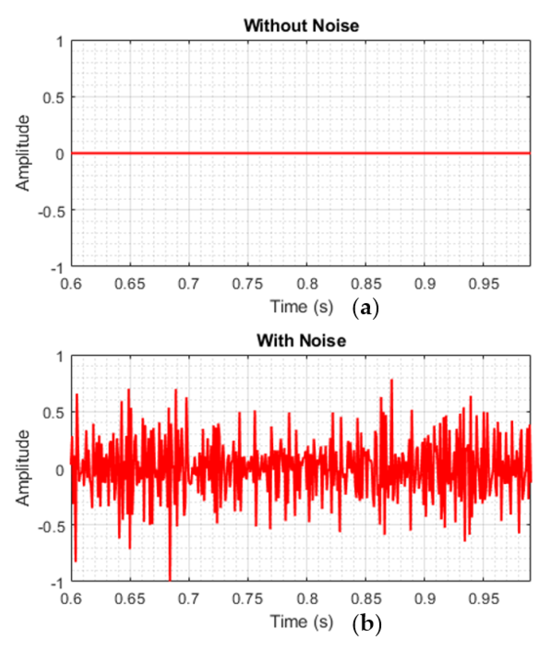
In many studies, the effect of noise on fault detection is not considered. In some studies, this issue may cause a wrong performance in fault detection when the signal is noisy. To investigate the mentioned problem, the method presented in [52] was used. This method uses differential protection for fault detection. To investigate this method, the sampled signals have been applied once without considering the noise and again by applying white Gaussian noise with SNR = 35 dB to the protection algorithm presented in [52]. Figure 20 shows the results of the evaluations. As is clear from this figure, the method presented in [52] has performed properly in the network without noise in normal conditions, but if the signal becomes noisy, it will issue the trip command in normal conditions.
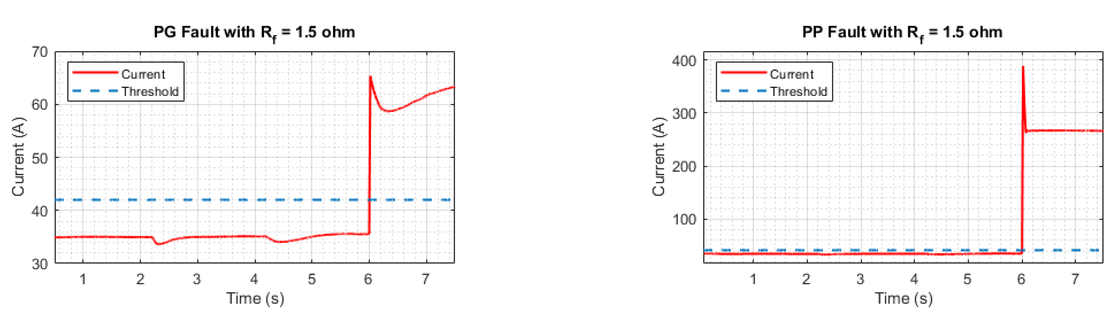
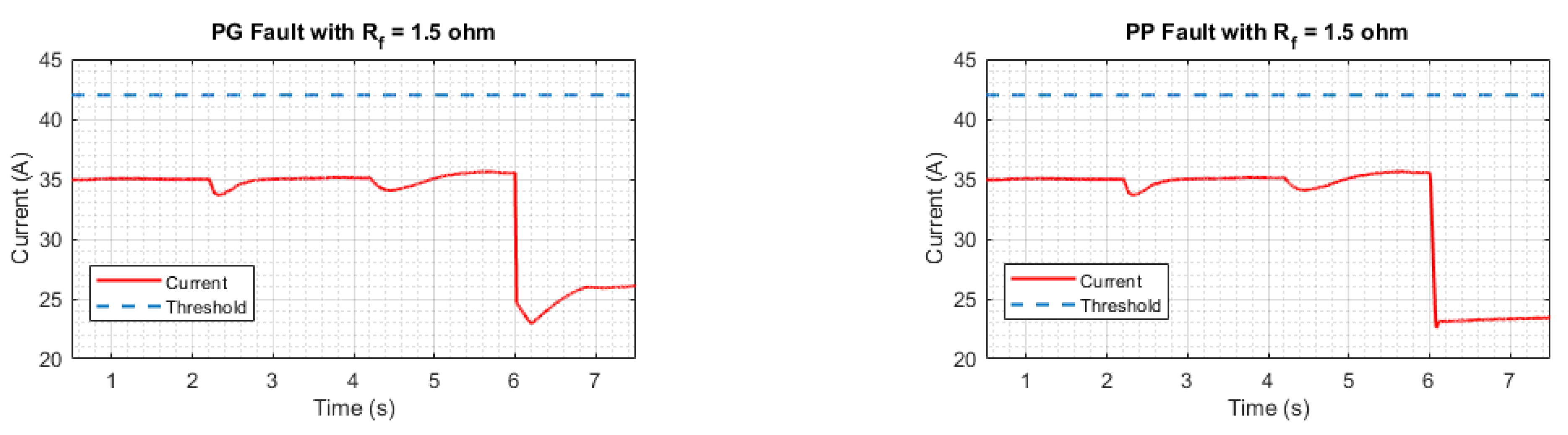
Although single-threshold overcurrent (OC) methods have shown good performances in different conditions, the use of these methods requires the use of a large number of IEDs in a microgrid. It is known that the use of several IEDs in a single-bus microgrid will increase the construction and operation costs. For example, the authors have tried to simulate the single-threshold OC method. According to the OC methods, the threshold value is 1.2 times the microgrid current. Figure 21 shows the performance of the single-threshold OC method when a fault occurs on the main bus of the microgrid. Although this figure shows the correct performance of this method in fault detection, by considering that the main purpose of this paper is using an IED to protect the DC single-bus microgrid, OC methods should be able to detect faults in other parts of the microgrid as well. For this reason, in Figure 22, the results of the OC method are presented for the occurrence of faults in the EV part. As is shown, this method does not have the ability to detect faults in different parts of the microgrid.
Finally, in order to conduct a comprehensive review, the method proposed in this paper has been compared with [6,34,53,54,55] in Table 9. As is clear from this table, the proposed method has worked successfully in different conditions.

5. Conclusions

In this paper, a fault detection method in a single-bus DC microgrid isolated from the grid with an IED and using the combined DMD-IF method is presented. The proposed method has been tested using a DC microgrid with a complete control system simulated in Simulink MATLAB. The results of the test of the proposed method indicate that the DMD-IF method is a very fast method in detecting all types of faults (PG and PP). In addition, the method has the ability to detect faults in different locations of the DC microgrid, including the main DC bus, EV, and PV. Also, this method is able to detect different types of faults by considering the effect of Gaussian white noise. The comparison shows the superiority of the proposed method over the existing methods.
Today, there are different types of storage systems, and researchers can focus on the effect of the presence of these storage devices on the protection methods of DC microgrids. In addition, it is very important to consider the effects of wind turbines in future research.

Author Contributions

Conceptualization, V.S.S.; Methodology, A.S.; Software, A.S. and B.T.; Validation, S.A.H.; Formal analysis, A.S., S.A.H. and V.S.S.; Writing—original draft, A.S., V.S.S. and B.T.; Writing—review & editing, S.A.H. and B.T.; Project administration, S.A.H. All authors have read and agreed to the published version of the manuscript.

Funding

This research received no external funding.

Institutional Review Board Statement

Not applicable.

Informed Consent Statement

Not applicable.

Data Availability Statement

Data are contained within the article.

Conflicts of Interest

The authors declare no conflict of interest.

References

  1. Elsayed, A.T.; Mohamed, A.A.; Mohammed, O.A. DC microgrids and distribution systems: An overview. Electr. Power Syst. Res. 2015, 119, 407–417. [Google Scholar] [CrossRef]
  2. Emhemed, A.A.; Burt, G.M. An advanced protection scheme for enabling an LVDC last mile distribution network. IEEE Trans. Smart Grid 2014, 5, 2602–2609. [Google Scholar] [CrossRef]
  3. Saeedifard, M.; Graovac, M.; Dias, R.F.; Iravani, R. DC power systems: Challenges and opportunities. In Proceedings of the IEEE PES General Meeting, Minneapolis, MN, USA, 25–29 July 2010; pp. 1–7. [Google Scholar]
  4. Altaf, M.W.; Arif, M.T.; Islam, S.N.; Haque, M.E. Microgrid protection challenges and mitigation approaches–A comprehensive review. IEEE Access 2022, 10, 38895–38922. [Google Scholar] [CrossRef]
  5. Cuzner, R.M.; Venkataramanan, G. The Status of DC Micro-Grid Protection. In Proceedings of the Industry Applications Society Annual Meeting, Edmonton, AB, Canada, 5–9 October 2008; pp. 1–8. [Google Scholar]
  6. Sharma, N.K.; Samantaray, S.R.; Bhende, C.N. VMD-enabled current-based fast fault detection scheme for DC microgrid. IEEE Syst. J. 2021, 16, 933–944. [Google Scholar] [CrossRef]
  7. Cairoli, P.; Rodrigues, R.; Zheng, H. Fault current limiting power converters for protection of DC microgrids. In Proceedings of the SoutheastCon 2017, Concord, NC, USA, 30 March–2 April 2017; pp. 1–7. [Google Scholar]
  8. Salomonsson, D.; Soder, L.; Sannino, A. Protection of Low-Voltage DC Microgrids. Power Deliv. IEEE Trans. 2009, 24, 1045–1053. [Google Scholar] [CrossRef]
  9. Farhadi, M.; Mohammed, O. Adaptive energy management in redundant hybrid DC microgrid for pulse load mitigation. IEEE Trans. Smart Grid 2014, 6, 54–62. [Google Scholar] [CrossRef]
  10. Dragičević, T.; Lu, X.; Vasquez, J.C.; Guerrero, J.M. DC microgrids—Part II: A review of power architectures, applications, and standardization issues. IEEE Trans. Power Electron. 2015, 31, 3528–3549. [Google Scholar] [CrossRef]
  11. Hosseini, S.A.; Taheri, B.; Sadeghi, S.H.H.; Nasiri, A. An Overview of DC Microgrid Protection Schemes and the Factors Involved. Electr. Power Compon. Syst. 2023, 1–31. [Google Scholar] [CrossRef]
  12. Zhang, L.; Tai, N.; Huang, W.; Wang, Y. Fault distance estimation-based protection scheme for DC microgrids. J. Eng. 2019, 2019, 1199–1203. [Google Scholar] [CrossRef]
  13. Li, X.; Song, Q.; Liu, W.; Rao, H.; Xu, S.; Li, L. Protection of nonpermanent faults on DC overhead lines in MMC-based HVDC systems. IEEE Trans. Power Deliv. 2012, 28, 483–490. [Google Scholar] [CrossRef]
  14. Mallick, R.K.; Patnaik, R.K. Fault analysis of voltage-source converter based multi-terminal HVDC transmission links. In Proceedings of the 2011 International Conference on Energy, Automation and Signal, Bhubaneswar, India, 28–30 December 2011; pp. 1–7. [Google Scholar]
  15. Jayamaha, D.; Lidula, N.; Rajapakse, A. Protection and grounding methods in DC microgrids: Comprehensive review and analysis. Renew. Sustain. Energy Rev. 2020, 120, 109631. [Google Scholar] [CrossRef]
  16. Tiwari, S.P.; Koley, E.; Ghosh, S. Communication-less ensemble classifier-based protection scheme for DC microgrid with adaptiveness to network reconfiguration and weather intermittency. Sustain. Energy Grids Netw. 2021, 26, 100460. [Google Scholar] [CrossRef]
  17. Shamsoddini, M.; Vahidi, B.; Razani, R.; Mohamed, Y.A.-R.I. A novel protection scheme for low voltage DC microgrid using inductance estimation. Int. J. Electr. Power Energy Syst. 2020, 120, 105992. [Google Scholar] [CrossRef]
  18. Bhargav, R.; Bhalja, B.R.; Gupta, C.P. Novel fault detection and localization algorithm for low-voltage DC microgrid. IEEE Trans. Ind. Inform. 2019, 16, 4498–4511. [Google Scholar] [CrossRef]
  19. Dhar, S.; Patnaik, R.K.; Dash, P. Fault detection and location of photovoltaic based DC microgrid using differential protection strategy. IEEE Trans. Smart Grid 2017, 9, 4303–4312. [Google Scholar] [CrossRef]
  20. Chauhan, P.; Gupta, C.; Tripathy, M. High speed fault detection and localization scheme for low voltage DC microgrid. Int. J. Electr. Power Energy Syst. 2023, 146, 108712. [Google Scholar] [CrossRef]
  21. Mazlumi, K.; Shabani, A. DC microgrid protection in the presence of the photovoltaic and energy storage systems. J. Oper. Autom. Power Eng. 2018, 6, 243–254. [Google Scholar]
  22. Wang, D.; Emhemed, A.; Burt, G.; Norman, P. Fault analysis of an active LVDC distribution network for utility applications. In Proceedings of the 2016 51st International Universities Power Engineering Conference (UPEC), Coimbra, Portugal, 6–9 September 2016; pp. 1–6. [Google Scholar]
  23. Park, J.; Candelaria, J. Fault Detection and Isolation in Low-Voltage DC-Bus Microgrid System. IEEE Trans. Power Deliv. 2013, 28, 779–787. [Google Scholar] [CrossRef]
  24. Baran, M.E.; Mahajan, N.R. Overcurrent Protection on Voltage-Source-Converter-Based Multiterminal DC Distribution Systems. Power Deliv. IEEE Trans. 2007, 22, 406–412. [Google Scholar] [CrossRef]
  25. Vanteddu, S.R.B.; Mohamed, A.; Mohammed, O. Protection design and coordination of DC Distributed Power Systems Architectures. In Proceedings of the 2013 IEEE Power & Energy Society General Meeting, Vancouver, BC, Canada, 21–25 July 2013; pp. 1–5. [Google Scholar]
  26. Li, C.; Rakhra, P.; Norman, P.; Niewczas, P.; Burt, G.; Clarkson, P. Modulated low fault-energy protection scheme for DC smart grids. IEEE Trans. Smart Grid 2019, 11, 84–94. [Google Scholar] [CrossRef]
  27. Monadi, M.; Zamani, M.A.; Candela, J.I.; Luna, A.; Rodriguez, P. Protection of AC and DC distribution systems Embedding distributed energy resources: A comparative review and analysis. Renew. Sustain. Energy Rev. 2015, 51, 1578–1593. [Google Scholar] [CrossRef]
  28. Li, X.; Dyśko, A.; Burt, G.M. Traveling wave-based protection scheme for inverter-dominated microgrid using mathematical morphology. IEEE Trans. Smart Grid 2014, 5, 2211–2218. [Google Scholar] [CrossRef]
  29. Jamali, S.Z.; Bukhari, S.B.; Khan, M.O.; Mehmood, K.K.; Mehdi, M.; Noh, C.H.; Kim, C.H. A high-speed fault detection, identification, and isolation method for a last mile radial LVDC distribution network. Energies 2018, 11, 2901. [Google Scholar] [CrossRef]
  30. Perera, N.; Rajapakse, A. Recognition of fault transients using a probabilistic neural-network classifier. IEEE Trans. Power Deliv. 2010, 26, 410–419. [Google Scholar] [CrossRef]
  31. Sharma, N.K.; Pattanayak, R.; Samantaray, S.R.; Bhende, C.N. A fast fault detection scheme for low voltage DC microgrid. In Proceedings of the 2020 21st National Power Systems Conference (NPSC), Gandhinagar, India, 17–19 December 2020; pp. 1–6. [Google Scholar]
  32. Mohanty, R.; Sahoo, S.; Pradhan, A.K.; Blaabjerg, F. A Cosine Similarity-Based Centralized Protection Scheme for dc Microgrids. IEEE J. Emerg. Sel. Top. Power Electron. 2021, 9, 5646–5656. [Google Scholar] [CrossRef]
  33. Ustun, T.S.; Ozansoy, C.; Zayegh, A. Modeling of a Centralized Microgrid Protection System and Distributed Energy Resources According to IEC 61850-7-420. Power Syst. IEEE Trans. 2012, 27, 1560–1567. [Google Scholar] [CrossRef]
  34. Monadi, M.; Gavriluta, C.; Luna, A.; Candela, J.I.; Rodriguez, P. Centralized Protection Strategy for Medium Voltage DC Microgrids. IEEE Trans. Power Deliv. 2017, 32, 430–440. [Google Scholar] [CrossRef]
  35. Mohanty, R.; Pradhan, A.K. Protection of smart DC microgrid with ring configuration using parameter estimation approach. IEEE Trans. Smart Grid 2017, 9, 6328–6337. [Google Scholar] [CrossRef]
  36. Taheri, B.; Hosseini, S.A. Detection of High Impedance Fault in DC Microgrid Using Impedance Prediction Technique. In Proceedings of the 2020 15th International Conference on Protection and Automation of Power Systems (IPAPS), Shiraz, Iran, 30–31 December 2020; pp. 68–73. [Google Scholar] [CrossRef]
  37. Abdali, A.; Mazlumi, K.; Noroozian, R. High-speed fault detection and location in DC microgrids systems using Multi-Criterion System and neural network. Appl. Soft Comput. 2019, 79, 341–353. [Google Scholar] [CrossRef]
  38. Bhargav, R.; Bhalja, B.R.; Gupta, C.P. Algorithm for fault detection and localisation in a mesh-type bipolar DC microgrid network. IET Gener. Transm. Distrib. 2019, 13, 3311–3322. [Google Scholar] [CrossRef]
  39. Jia, K.; Zhao, Q.; Feng, T.; Bi, T. Distance protection scheme for DC distribution systems based on the high-frequency characteristics of faults. IEEE Trans. Power Deliv. 2019, 35, 234–243. [Google Scholar] [CrossRef]
  40. Li, C.; Rakhra, P.; Norman, P.J.; Burt, G.M.; Clarkson, P. Multi-sample differential protection scheme in DC microgrids. IEEE J. Emerg. Sel. Top. Power Electron. 2020, 9, 2560–2573. [Google Scholar] [CrossRef]
  41. Taheri, B.; Shahhoseini, A. Direct current (DC) microgrid control in the presence of electrical vehicle/photovoltaic (EV/PV) systems and hybrid energy storage systems: A Case study of grounding and protection issue. IET Gener. Transm. Distrib. 2023, 17, 3084–3099. [Google Scholar] [CrossRef]
  42. Zhang, H.; Rowley, C.W.; Deem, E.A.; Cattafesta, L.N. Online dynamic mode decomposition for time-varying systems. SIAM J. Appl. Dyn. Syst. 2019, 18, 1586–1609. [Google Scholar] [CrossRef]
  43. Krake, T.; Reinhardt, S.; Hlawatsch, M.; Eberhardt, B.; Weiskopf, D. Visualization and selection of Dynamic Mode Decomposition components for unsteady flow. Vis. Inform. 2021, 5, 15–27. [Google Scholar] [CrossRef]
  44. Wilches-Bernal, F.; Reno, M.J.; Hernandez-Alvidrez, J. A dynamic mode decomposition scheme to analyze power quality events. IEEE Access 2021, 9, 70775–70788. [Google Scholar] [CrossRef]
  45. Muniraju, A. Analysis of Dynamic Mode Decomposition; The University of Wisconsin-Milwaukee: Milwaukee, WI, USA, 2018. [Google Scholar]
  46. Taheri, B.; Salehimehr, S.; Razavi, F.; Parpaei, M. Detection of power swing and fault occurring simultaneously with power swing using instantaneous frequency. Energy Syst. 2020, 11, 491–514. [Google Scholar] [CrossRef]
  47. Salehimehr, S.; Taheri, B.; Faghihlou, M. Detection of power swing and blocking the distance relay using the variance calculation of the current sampled data. Electr. Eng. 2021, 104, 913–927. [Google Scholar] [CrossRef]
  48. Shen, L.; Cheng, Q.; Cheng, Y.; Wei, L.; Wang, Y. Hierarchical control of DC micro-grid for photovoltaic EV charging station based on flywheel and battery energy storage system. Electr. Power Syst. Res. 2020, 179, 106079. [Google Scholar] [CrossRef]
  49. Conti, S.; Raffa, L.; Vagliasindi, U. Innovative solutions for protection schemes in autonomous MV micro-grids. In Proceedings of the 2009 International Conference on Clean Electrical Power, Capri, Italy, 9–11 June 2009; pp. 647–654. [Google Scholar]
  50. Jae-Do, P.; Candelaria, J.; Liuyan, M.; Dunn, K. DC Ring-Bus Microgrid Fault Protection and Identification of Fault Location. Power Deliv. IEEE Trans. 2013, 28, 2574–2584. [Google Scholar] [CrossRef]
  51. Nazari, A.A.; Razavi, F.; Fakharian, A. A new power swing detection method in power systems with large-scale wind farms based on modified empirical-mode decomposition method. IET Gener. Transm. Distrib. 2022, 17, 1204–1215. [Google Scholar] [CrossRef]
  52. Dashtdar, M.; Rubanenko, O.; Danylchenko, D.; Hosseinimoghadam, S.M.S.; Sharma, N.K.; Baiai, M. Protection of DC microgrids based on differential protection method by fuzzy systems. In Proceedings of the 2021 IEEE 2nd KhPI Week on Advanced Technology (KhPIWeek), Kharkiv, Ukraine, 13–17 September 2021; pp. 22–27. [Google Scholar]
  53. Emhemed, A.A.; Fong, K.; Fletcher, S.; Burt, G.M. Validation of fast and selective protection scheme for an LVDC distribution network. IEEE Trans. Power Deliv. 2016, 32, 1432–1440. [Google Scholar] [CrossRef]
  54. Kong, L.; Nian, H. Fault detection and location method for mesh-type DC microgrid using pearson correlation coefficient. IEEE Trans. Power Deliv. 2020, 36, 1428–1439. [Google Scholar] [CrossRef]
  55. Mola, M.; Afshar, A.; Meskin, N.; Karrari, M. Distributed Fast Fault Detection in DC Microgrids. IEEE Syst. J. 2022, 16, 440–451. [Google Scholar] [CrossRef]
Figure 1. Sampled signals of voltage and current under normal network conditions.
Sustainability 15 16269 g001
Figure 2. Sampled signals of voltage and current under fault conditions.
Sustainability 15 16269 g002
Figure 3. Generated eigenvector under normal network conditions.
Sustainability 15 16269 g003
Figure 4. Generated eigenvector under disturbance in the network.
Sustainability 15 16269 g004
Figure 5. The reconstructed signal (a) in normal network conditions (b) in fault conditions.
Sustainability 15 16269 g005
Figure 6. Algorithm of the proposed method.
Sustainability 15 16269 g006
Figure 7. Voltage and current sampled by the IED when a fault occurred (a) in EV, (b) in PV, and (c) in the DC bus.
Sustainability 15 16269 g007
Figure 8. Proposed algorithm for determining threshold values.
Sustainability 15 16269 g008
Figure 9. Sample DC microgrid.
Sustainability 15 16269 g009
Figure 10. The performance of the proposed method during the occurrence of PG faults in the DC microgrid main bus.
Sustainability 15 16269 g010
Figure 11. The performance of the proposed method during the occurrence of PG faults in the PV part of the DC microgrid.
Sustainability 15 16269 g011
Figure 12. The performance of the proposed method during the occurrence of PG faults in the EV part of the DC microgrid.
Sustainability 15 16269 g012
Figure 13. The performance of the proposed method during the occurrence of PP faults in the DC microgrid main bus.
Sustainability 15 16269 g013
Figure 14. The performance of the proposed method during the occurrence of PP faults in the PV part of the DC microgrid.
Sustainability 15 16269 g014
Figure 15. The performance of the proposed method during the occurrence of PP faults in the EV part of the DC microgrid.
Sustainability 15 16269 g015
Figure 16. The performance of the proposed method during the occurrence of PG and PP faults in the DC microgrid main bus (in the grid-connected mode).
Sustainability 15 16269 g016
Figure 17. The performance of the proposed method during the occurrence of PG faults in different parts of the DC microgrid with white Gaussian noise.
Sustainability 15 16269 g017
Figure 18. The performance of the proposed method during the occurrence of PP faults in different parts of the DC microgrid with white Gaussian noise.
Sustainability 15 16269 g018
Figure 19. The performance of the proposed method during the occurrence of PG faults in the DC microgrid without batteries.
Sustainability 15 16269 g019
Figure 20. Evaluation of the method presented in [52]: (a) signal without noise and (b) signal with noise.
Sustainability 15 16269 g020
Figure 21. The performance of the OC method during the occurrence of PG and PP faults in the DC microgrid main bus (Figure 9).
Sustainability 15 16269 g021
Figure 22. The performance of the OC method during the occurrence of PG and PP faults in the EV part of the DC microgrid (Figure 9).
Sustainability 15 16269 g022
Table 1. Study cases for calculating the threshold values.
Study CasesFault LocationFault TypeFault Impedance (ohm)Distance between the IED and the Fault Location (km)
1F1PG1.500
2F1PP1.500
3F2PG1.501
4F2PP1.501
5F3PG1.501
6F3PP1.501
7F1PG2.500
8F1PP2.500
9F2PG2.501
10F2PP2.501
11F3PG2.501
12F3PP2.501
13F1PG50
14F1PP50
15F2PG51
16F2PP51
17F3PG51
18F3PP51
19F1PG100
20F1PP100
21F2PG101
22F2PP101
23F3PG101
24F3PP101
Table 2. Sample DC microgrid parameters.
ParameterValue
DC bus voltage600 V
AC bus voltage380 V
PV power20 kW
Charging and discharging current of EV15 A and 10 A
BatteryLifePO4, 360 V, 100 Ah
Flywheel10 kW, 10,000 r/min, 5000 r/min
AC loads5 kW each load
DC load5 kW
Lines parameters
Cross-section240 mm2
Cable resistance0.125 Ω/km
Cable inductance0.232 Ω/km
L1–L4 lines length1 km
Table 3. The results of the detection of PG faults in the DC microgrid main bus.
Rf (Ω)25201052.51.5
Peak value12.4312.4512.7413.4514.5615.76
Detection time (ms)<1<1<1<1<1<1
Table 4. The results of the detection of PG faults in the PV part of the DC microgrid.
Rf (Ω)1052.51.5
Peak value−4.03−4.18−4.23−4.45
Detection time (ms)<1<1<1<1
Table 5. The results of the detection of PG faults in the EV part of the DC microgrid.
Rf (Ω)1052.51.5
Peak value−6.01−6.03−6.14−6.16
Detection time (ms)2222
Table 6. The results of the detection of PP faults in the DC microgrid main bus.
Rf (Ω)1052.51.5
Peak value7.8410.1213.8318.36
Detection time (ms)<1<1<1<1
Table 7. The results of the detection of PP faults in the PV part of the DC microgrid.
Rf (Ω)1052.51.5
Peak value−4.7−4.91−5.41−7.63
Detection time (ms)24211413
Table 8. The results of the detection of PP faults in the EV part of the DC microgrid.
Rf (Ω)1052.51.5
Peak value−3.92−3.99−4.08−5.7
Detection time (ms)24242414
Table 9. Comparison of the proposed method with other studies.
Objects[55][6][34][53][54]Proposed Method
Considering noiseYesYesNoNoNoYes
Detecting PP and PG faults in EV and PV partsNoNoNoNoNoYes
Requiring communication linksYesYesYesYesNoNo
Considering energy storage systemsNoYesNoNoNoYes
Disclaimer/Publisher’s Note: The statements, opinions and data contained in all publications are solely those of the individual author(s) and contributor(s) and not of MDPI and/or the editor(s). MDPI and/or the editor(s) disclaim responsibility for any injury to people or property resulting from any ideas, methods, instructions or products referred to in the content.

