Abstract
Goaf restoration is an important part of urban space management. With mining of coal resources, appearance of goaf and subsidence areas causes serious geological disasters and environmental and ecological problems, which significantly affect urban safety, development, and construction. Therefore, repair of goafs is crucial. In this study, the goaf of Jingmen Garden Expo Park was taken as an example. Through acquisition of engineering geological condition parameters and data on the goaf combined with the mechanical parameters selected for the site, the deformation mechanism of the overlying strata of the goaf was analyzed, and a numerical model of the goaf was established. On this basis, FLAC(3D) was used for numerical simulation to evaluate the stability of the goaf; the suitability of the site was evaluated and divided, and the ecological restoration model of the goaf in Jingmen Garden Expo Park was studied. The results showed that different degrees of ecological restoration and construction of various facilities and buildings could be carried out in the goaf. Based on the varying degrees of stability in the goaf, an appropriate restoration path is suggested according to the suitability of these different degrees. The green, innovative, and sustainable restoration design of the goaf can be carried out according to these restoration paths in order to establish a green ecological system in Jingmen Garden Expo Park.
1. Introduction
In China, goaf restoration is an important component of urban construction [1]. Urban studies statistics show that 55% of the world’s population lives in cities, and the urban population is expected to grow by more than 15% by 2050 [2]. Due to the rapid development of spatial urbanization and expansion of the urban population, most cities face the challenge of unsustainable development caused by depletion of surrounding natural resources and waste discharge [3].
By 2022, China’s mine development will cover 2,907,200 hectares, of which abandoned mines account for 30.35%, and only 4.64% of the mining area has been restored and treated [4]. Over-exploitation of mineral resources has greatly affected ecology and human settlement [5]. Traditional mining area governance mostly focuses on ecological and environmental engineering governance, limited to greening and land reclamation, and ignores the multiple interactions between the environment and society [6]. Faced with the dilemma of the high cost of engineering management and low comprehensive benefits, many abandoned mining areas lack management. Underground mining methods for mineral resources can generally be divided into the empty field method, caving method, and filling method, all of which use back mining to naturally form a goaf. A large number of goafs will destroy the equilibrium state of the original rock stress and form a secondary stress field, which affects the mining conditions of the underground ore body (the ore pillar is destroyed by compression and deformation) and causes roadway maintenance to become increasingly difficult [7]. Roof instability in the goaf, movement and deformation of the rock formation, and subsidence of the ground can lead to serious casualties, damage, and waste of resources [8]. As the scale of the mining of mineral resources is expanding, geological hazards caused by goafs are also increasing, which has a serious impact on the stability of mining areas [9]. The stability of a goaf directly affects personal and equipment safety during the mining process. Therefore, goafs have become one of the major hidden dangers affecting the safety of mine production [10].
The earliest regeneration of abandoned mining sites in China began in the late Qing Dynasty, and, from the 1950s to the 1990s, regeneration of mining sites was mainly based on agricultural reclamation. Since the beginning of the 21st century, the concept of environmental governance has gradually changed [11], and the artistic method of design has become an important means in mining regeneration [12]. Construction of national mine parks started in 2006, and, as of this year, there are 87 [13]. Before the 1970s, governance of abandoned mining areas in many countries, such as those of Europe and the United States, mainly focused on land reclamation projects and technologies [14]. In the 1970s, land art intervened in regeneration of mining areas. Several important collective art exhibitions in the United States have recorded attempts and explorations of artists in the field of land art, providing new perspectives and methods for regeneration of abandoned mining areas. Since the 1990s, regeneration of mining areas in Germany has been the most representative, among which the Nord Duisburg Park planned by IBA has become a model for transformation [15,16]. After entering the 21st century, the rise and development of ecological aesthetics, landscape urbanism, green infrastructure, and other theories promoted development of abandoned mining areas in the direction of multiple regenerations [17].
Ecological restoration of mined-out areas based on the stability of the overlying rock has been affected by high-intensity development and construction, unreasonable utilization, and natural disasters for a long time, resulting in serious damage and degradation in the mining ecosystem, ecological dysfunction, and reduced ecological product supply capacity. Based on safety investigations, comprehensive measures, both engineering and non-engineering, are taken to carry out ecological restoration, ecological improvement, ecological reconstruction, ecological rehabilitation, and conscious activities in the goaf ecosystem [18]. These are important means to achieve optimization of the spatial pattern of the country, structural restoration of the ecosystem, and enhancement of ecological functions [19]. Compared with traditional goaf repair, the most important feature of these measures is that they improve the survey accuracy of the goaf. In addition to the traditional geophysical technology method, the combination of geological radar and seismic imaging methods provides more attention to integrity and regionality and promotes full repair of damaged areas. Goafs are the product of the close interaction between nature and the cultural driving force, and most of their constituent elements belong to the cultural landscape [20]. If a reasonable restoration design is involved in the entire life cycle of an abandoned mining area, it can promote mining of regional cultural and aesthetic values and protection and utilization of industrial heritage and tourism resources, solve the dilemma of traditional governance, and promote interconnection and synergy of various subsystems in the abandoned mining area, driving the overall mining system to transition to a state with a more orderly structure and function [21].
Researchers have invested a great deal of time into investigating the stability of goaf slopes and have achieved good results; however, there are still no studies evaluating the stability of the overlying rock and the site suitability of the goafs. In addition, there are few studies on ecological restoration of coal mine goafs based on safety investigation and evaluation. This study took the goaf of Jingmen City Garden Expo Park Coal Mine as an example. Through interpretation of the current situation of the goaf in Jingmen City Garden Expo Park, the engineering geological conditions of the goaf were surveyed and the appropriate mechanical parameters for the site were selected. At the same time, a theoretical analysis of the deformation mechanism and roof stability of the goaf was carried out, and a numerical model of movement deformation was established. In order to evaluate the stability and suitability of the park, FLAC(3D) was used to simulate and analyze the movement deformation values of the Jingmen Garden Expo Park goaf, investigate the stability of its surrounding rocks, and study the stability of the goaf itself. The purpose of this study was to produce an effective analysis of Jingmen Garden Expo Park’s stability and evaluate the park’s safety. The findings of the study can help with both ecological restoration and local residents’ safety.
2. Data and Methods
2.1. Study Area
The Jingmen Garden Expo Park project is located in the Shuangxi area of Zhanghe New District, with a total land area of approximately 155 hectares; the location of the zone is shown in Figure 1. The site was originally planned as a vegetable base in the eastern suburbs, with a mass of residential houses scattered in the vicinity. Currently, the planning area is for key public building projects in the Shuangxi area of Jingmen, shown in Figure 2. Most of the surrounding roads and buildings have now been constructed.
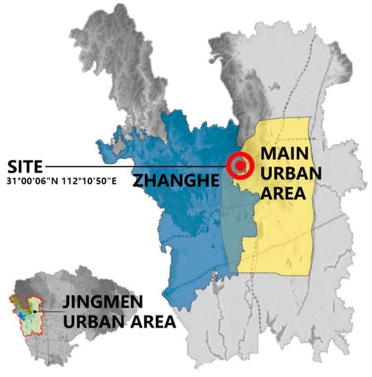
Figure 1.
Location map of Jingmen Garden Expo Park.
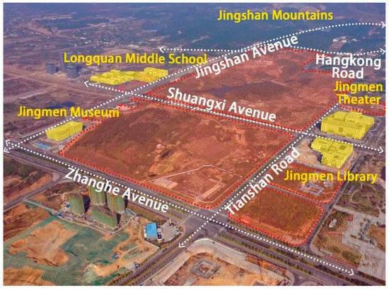
Figure 2.
The project site and surroundings of Jingmen Garden Expo Park.
Exploration and use of coal mines in Jingmen City have greatly increased the local economy. However, the enormous number of empty spaces left over from the early days of coal mining has made planning and building urban redevelopment projects in the area quite challenging. The coal mining within the area is old, and the transfer of mineral rights is frequent, where more than 10 companies and individuals have visited the survey area to carry out mining activities. Most were not recorded, while some were classified as indiscriminate mining, as shown in Table 1. A lack of information on the distribution, scale, and burial depth of the coal mining area among other limitations have resulted in hidden danger and seriously restricted the planning, layout, and construction of the park site.

Table 1.
Basic information about the mines in the survey area.
2.2. Data Acquisition
2.2.1. Engineering Geological Conditions of the Goaf in Garden Expo Park
The topography of the region is high in the north and low in the south, with significant topographic differences between the two regions. The northwestern part of the territory is occupied by the Jing Mountain Range, while the southeastern extension features low mountainous and hilly terrain, where the mountainous terrain falls along the tectonic line. As a result of uncontrolled coal mining, landfills, and municipal construction, historical problems have become apparent. The site has undergone deterioration in water quality, broken hills, and destroyed vegetation. There are currently many mine goafs within the area, which were previously managed via the natural collapse method, with engineering mining causing more serious damage to the surface vegetation. The mine ballast sites are relatively large in scale and the majority of the closed mine shafts have now been buried naturally and artificially, although a small number of shafts are used by residents as water extraction points for farming and aquaculture. The surface features are no longer evident as most of the ballast dumps have been converted into agricultural and forestry land; however, the subsurface conditions of the mine goafs will directly affect construction in the site. By employing engineering restoration and biological restoration, damage to mountains caused by geological and geomorphological destruction and vegetation related to protection of animal and plant diversity and water conservation can be restored [22]. Comprehensive transformation and improvement can then be carried out to give full play to their economic benefits and landscape value based on ensuring safety and ecological functions [23].
According to our drilling project, the lithology in the evaluation area is mainly characterized by gravel-bearing silty clay, mudstone, silty mudstone, carbonaceous mudstone, argillaceous siltstone, siltstone, fine-grained feldspar quartz sandstone, medium-fine-grained sandstone, and medium-coarse-grained sandstone; essentially, it is composed of sandstone and conglomerate. According to the rock and soil type, rock and soil structure, and mechanical properties, the rock (including soil) at the site was divided into two categories and five rock sub-types.
2.2.2. Selection of Physical and Mechanical Geotechnical Soil Parameters in the Garden Expo Park Goaf
According to the mine geological survey report published by Yinshan Coal Mine, the Code for investigation of geotechnical engineering in the coal mine goaf [24], combined with the engineering geological analogy method, the values of the physical and mechanical parameters of the soil mass and rock in the field were determined, as shown in Table 2.
Table 2.
Recommended values for rock physical mechanical parameters.
2.3. Research Methods
2.3.1. Analysis of the Deformation Mechanism of the Mining Area of Garden Expo Park
Ground subsidence is the most direct manifestation of the deformation of an underground goaf as it effectively releases in situ stress in the goaf; however, the caving, crushing, and bending subsidence of the rock mass during the deformation process destroys the integrity of the overlying rock [25]. The overlying strata in the goaf are mainly Jurassic and Triassic argillaceous siltstone, silty mudstone, carbonaceous shale, and coal seam, with poor overall rock cementation [26]. Cut-and-fall ground subsidence is a one-time rapid deformation process. It usually forms a bottomless and inverted funnel-shaped subsidence pit, and crisscross tensile cracks appear on the surface above the goaf. The occurrence of deep pit subsidence establishes a hydraulic connection between rainfall and the goaf. Rainwater will directly enter the goaf through the subsidence pit, aggravating the damage to the mine pillars in the goaf around the subsidence pit and thereby affecting the stability of the goaf.
According to the Code for investigation of geotechnical engineering in the coal mine goaf [24], before excavation of the underground space, the rock mass in the stratum is in a state of natural stress. To a large extent, this state can be considered as an ideal equilibrium state without shear stress; that is, the principal stress is approximately equal, and both are compressive stress. A small cubic rock block is arbitrarily taken from the rock body at a large burial depth. At this time, the block is in a state of three-direction force, as shown in Figure 3. The vertical stress σz is formed by the pressure of the weight of the overlying rock, which causes the block to move and deform in three directions, namely vertical compression and lateral expansion. However, due to the lateral limits of the adjacent rock mass, its deformation can only be zero; thus, the lateral stresses σx and σy of the block are formed. These processes are shown in Equations (1) and (2):
where γ is the average bulk density of the overlying rock; H is the thickness of the overlying rock layer in the excavation space in the rock stratum; and μ is Poisson’s ratio. For most rocks, the μ value is usually between 0.2 and 0.3; that is, the horizontal stress due to self-weight in the stress state of the rock body is about 25% to 43% of the vertical stress, and it is all compressive stress. Assuming that the block is in a plastic state, we obtain σx = σy = σz = γH. Usually, the underground rock mass is in an elastic-plastic state.
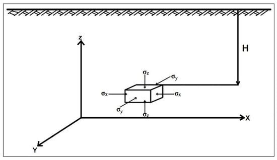
Figure 3.
Stress state in underground rock.
Due to the gravitational effect of the rock formation and the pressure formed by the geological structure, the volume and shape of the rock change, as shown in Equation (3), and the elastic energy accumulated by the compression of the rock volume is expressed as
The elastic energy gathered by the change in rock shape is shown in Equation (4), where E is the elastic modulus and G is the shear elastic modulus:
It can be seen from the above two equations that, with an increase in the depth of the excavated stratum from the ground, the elastic energy accumulated by the rock strata in the elastic state will increase with the square relationship. When this elastic energy is released under certain conditions, it will cause movement and deformation of the rock mass. Due to mining of underground minerals, excavation for underground engineering, and destruction of aquifers, excavation spaces will be formed underground, which will redistribute the original natural stress field in the stratum rock body to achieve a new equilibrium state. At this time, a decompression zone is generated on the four walls of the excavation space, the compressive stress inside the excavation space disappears, and the elastic energy accumulated by the rock formation will be released, causing the rock to be crushed and protrude into the excavation space. A decompression zone is generated at the bottom, and the compressive stress is replaced by tensile stress, which causes damage to the surrounding rocks and movement and deformation of the stratum near the excavation space. Under the action of its weight and the gravity of the overlying rock layer, the roof rock layer in the upper part of the excavation space bends downward; human engineering activities on the ground will also exacerbate this movement process. When the internal tensile stress of the rock mass exceeds the rock strength limit, the roof layer is fractured, breaks, and collapses. Above the band of rock formations where the rock has broken and collapsed, the hard rock formation usually moves in the direction normal to the layer and along the layer in the form of rock beams or cantilevers. The whole process of rock movement and deformation includes rock caving, fractures, layer separation, fissures, sliding along the layer, bending, and other failure forms. After this rock movement and deformation process reaches the surface, a subsidence basin that is much larger than the underground excavation space is usually formed, resulting in surface subsidence, tilt deformation, curvature deformation, horizontal movement and deformation, etc. In addition, it may also cause discontinuous deformation.
2.3.2. Theoretical Analysis of the Stability of the Goaf in Garden Expo Park and Establishment of a Numerical Model
- (1)
- Analysis of cavitation and fracture zone
After the mining of a project, caving zones, fault zones, and bending zones are easily formed in the overlying rock under the action of gravity [27]. As a result, the internal structure of the rock mass is damaged to varying degrees. Here, mainly based on the empirical calculation formula for roof stability recommended in the Code for investigation of geotechnical engineering in the coal mine goaf [24] and the Engineering Geology Handbook [28], the damage height of the overlying rock and the roof stability of the goaf were calculated.
The comprehensive inclination of the coal seam in the evaluation area is 45° to 53°, belonging to the inclined goaf (mineral seam), and the overlying rocks are mainly Triassic, Jurassic, and argillaceous siltstone, which belong to the Cenozoic relatively soft–extremely soft rock. According to the Code for investigation of geotechnical engineering in the coal mine goaf [24] and the Engineering Geology Handbook [28], as shown in Equations (5) and (6), the formulae for calculating the height of the caving zone and fissure zone are as follows:
① Calculation of the height of the caving zone:
② Calculation of the height of the fissure zone:
In the above equations, is the height of the caving zone, is the height of the water-conducting fissure zone, and is the cumulative mining thickness of the ore seam (m).
- (2)
- Analysis of the natural balance method
As shown in Figure 4, according to the Engineering Geology Handbook [28], after the ore seam gives out, its roof block (ABCD) sinks due to the action of gravity (W), and the wedges on both sides (ABM and CDM) also exert horizontal pressure (P) on it. Therefore, it is acted on by the frictional resistance (f) generated by the action of P on both surfaces AB and CD. As shown in Equation (7), taking the unit length of the roadway as the calculation unit, the pressure acting on the roof of the roadway is expressed as follows:
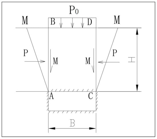
Figure 4.
Schematic diagram of goaf roof stability.
As shown in Equation (8), when H increases to a certain depth, the top rock layer is in a natural balance (i.e., Q = 0), and the H value at this time is called the critical depth, H0.
In the above equations, Q is the pressure on the roof of the goaf section (kN/m); G is the total stress on the rock strata on the roof per unit length of the roadway (kN/m); B is the roadway width (m), taken as 10.0 m; φ is the internal friction angle (°) of the rock formation, taken as 40°; f is the frictional resistance of the sidewall per unit length of the roadway (kN/m); γ is the severity of overburden (kN/m3); and H is the burial depth of the roadway roof (m). When H ≤ H0, the top plate is unstable; when H0 < H ≤ 1.5 H0, the top plate has poor stability; and, when H0 > 1.5 H0, the top plate is stable.
The calculation results are shown in Table 3. The critical thickness of the roof of the goaf was calculated as 54.95 m.
Table 3.
Roof stability critical calculation.
The calculation results show that, when the thickness of the overlying rock layer in the goaf is less than 54.95 m, the roof of the goaf is in an unstable state; when the thickness of the overlying rock layer is less than 82.42 m (1.5 H0), the roof is stable.
- (3)
- Building a numerical model of moving deformation
The rock mass is not only a material but, more importantly, a geological structural object [29]. It has heterogeneous, non-continuous, non-linear, and complex loading and unloading conditions and boundary conditions; as such, rock mechanics problems usually cannot be solved simply by analytical methods [30]. In contrast, numerical analysis methods have wider applicability. They can not only simulate the complex mechanical and structural characteristics of the rock mass but can also easily analyze various boundary value problems and construction processes and forecast projects. Here, to better analyze the ground deformation characteristics of the goaf and simplify the model, the goaf section left after a coal line was mined was selected for static calculation to analyze the characteristics of the stress ground deformation in the goaf of the coal mine.
- Calculation range
In this numerical simulation analysis, a typical section (as shown in Figure 5) was selected to analyze the stability of the goaf. To facilitate the simulation calculation, the geological model of the profile was generalized. After the model was generalized, the size of the section calculation model was 400 m × 1 m × 230 m, the mined height of the goaf was 1.5 to 2 m, and the size of the model met the calculation accuracy requirements.
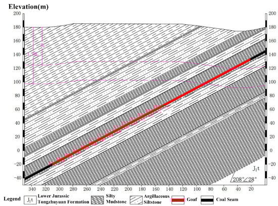
Figure 5.
Generalized diagram of typical section model of goaf.
- Boundary conditions
Through the analysis and comparison of the geometric models and on the basis of studying the geological model of the gypsum mine goaf, the geometric boundary conditions were determined as follows: the bottom of the model was constrained by displacement in the Z-direction, and the displacement in the Z-direction was fixed; the displacement in the Y-direction was fixed; the displacement in the X-direction was fixed; and the other areas were taken as free boundaries.
- Constitutive model selection
The essence of the constitutive model is to describe the relationship between stress and strain. For different materials, a constitutive model that conforms to their individual characteristics should be used to better analyze the variation law of stress and strain. The simulation results show that the Mohr-Coulomb Elastoplastic Model is a more applicable constitutive model for the tension calculation of rock materials. It can be used in the FLAC(3D) software to simulate various situations, including slope stability, underground excavation, and seepage. Therefore, the Mohr–Coulomb constitutive model is more suitable for calculation and analysis of the coal mine goaf model.
- Initial stress calculation
It is generally believed that the initial stress field is mainly generated by the self-weight of the rock mass and the geological tectonic force. Some other influencing factors, such as stress caused by temperature, are often ignored in underground cavern projects that are buried at shallow depths and will not be affected by geothermal energy. Numerical simulations generally use limited in situ stress observations along with topographic and geomorphological data, referring to the general law of in situ stress field distribution, and perform regression fitting to obtain a more reasonable initial in situ stress field, which is used as a reference for further analysis of the construction process of underground engineering on the basis of rock stability. The goaf of the coal mine in Jingmen Garden Expo Park is buried at a shallow depth; therefore, its initial stress is mainly generated by the self-weight of the rock mass.
- Simulate and Solve
The calculation program to simulate mining was based on the stress distribution of the previous calculation step according to the change in the overall stiffness of the structure, and the mining release load was applied to solve the stress field after mining. In this calculation, the goafs in the simulated mining step were excavated using the null command at one time. After excavation, some key nodes and units could be tracked using the hist command and then calculated.
2.3.3. Ecological Restoration Model of the Mined-Out Area of Jingmen Garden Expo Park
The ecological restoration of goafs can be divided into two types of areas and four modes, including:
- (1)
- General restoration area: Most of these areas adopt a natural restoration mode or artificial assistance mode [31]. The natural recovery mode mainly employs measures such as setting up warning signs, tying galvanized barbed wire, planting fence thorns, and setting up protective fences for enclosure, while the manual auxiliary mode mainly adopts measures such as slope adjustment, waste gravel cleaning, topsoil backfilling, and land leveling.
- (2)
- Key restoration areas: In these areas, an engineering restoration mode or transformation utilization mode is generally adopted [32]. Backfilling, fencing, and landscaping measures can be adopted for deep quarrying pits [33,34]. For mining land with a gentle slope (slope less than 35°), measures such as laying grass blankets, planting bags, foreign soil, laying three-dimensional nets, and laying geogrids can be adopted. For slopes greater than 35° and less than 70°, soil bagging, spraying and mixing plants, and retaining wall greening measures can be adopted. For slopes greater than 70°, floating board planting troughs, ecological concrete, construction of fish scale pits and swallow nests, spraying slope protection, hanging net spraying, drilling and climbing vines, greening, landscaping, and other measures can be utilized [35]. For abandoned mines with a soil slope of more than 10 m and a rock slope of more than 20 m, slope-cutting and grading measures may be adopted if the surrounding land allows.
3. Results
3.1. Analysis of the Calculation Results for the Stability of the Mined-Out Area of the Garden Expo Park
3.1.1. Overlying Rock Stability Analysis
After calculation, the minimum and maximum thicknesses of the overlying rock mass in the goaf due to the pressure of the surrounding rock caused by deformation and damage (caving height + fault zone height) were 40.19 m and 48.33 m in the first key exploration area, 36.45 m and 44.24 m in the second area, and 49.77 m and 57.57 m in the third area, respectively. The detailed calculation results are shown in Table 4.
Table 4.
Calculation results for rock damage height.
According to our survey, during mining of coal in the evaluation area, mining was stopped in most of the coal seams when they were 15 to 25 m away from the ground. Therefore, the outcrop line of the mineable coal seam does not meet the requirements of the overlying rock mass in the goaf due to the surrounding rock pressure. The minimum thickness and maximum thickness required to produce deformation and failure are insufficient, and the stability of the overlying rock mass in the goaf is insufficient.
3.1.2. Numerical Simulation Analysis of Goaf Movement Deformation
- (1)
- Section Displacement Stress Analysis
Figure 6 and Figure 7 show the displacement vector diagram and displacement cloud map of the goaf, respectively. After the coal seam was excavated, the direction of the overall displacement vector in the calculated section was deflected towards the goaf to varying degrees, which is in line with the deformation of the underground excavation of the inclined coal seam law. The maximum displacement in the stratum was located at the roof in the middle of the goaf, with a displacement of 4.797 cm, and the displacement decreased gradually from the roof of the goaf to the surface. The surface displacement and deformation were distributed on the left side of the coal line in the section. Starting from the coal seam along the direction of goaf excavation, the surface displacement value changed from small to large and then back to small, showing an asymmetric distribution, and the surface displacement varied between 0 and 4.5 cm.
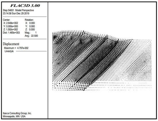
Figure 6.
Displacement vector.
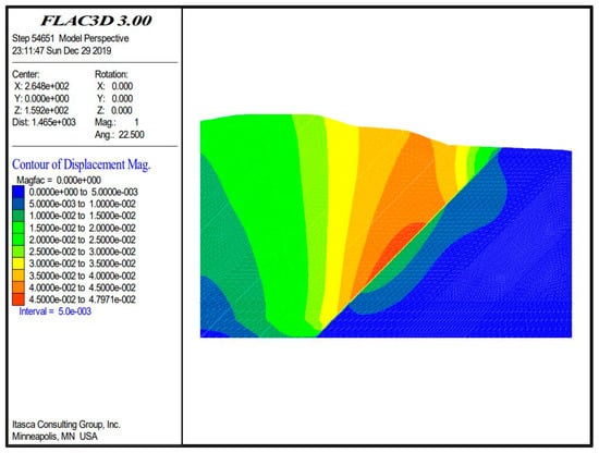
Figure 7.
Displacement cloud map.
Figure 8 shows the vertical (Z-direction) displacement cloud of the goaf; as the distance from the mining area decreases, the vertical displacement from left to right first increases and then decreases. In view of this, the vertical displacements above the top plate of the goaf were all negative; i.e., the direction of displacement was consistent with the direction of gravity, and the displacement gradually decreased from the top plate of the goaf to the surface. The displacement of the bottom plate of the mine room was positive, opposite to the direction of gravity, and the displacement changes were small, which is in line with the general rule of underground deposit excavation. The surface above the goaf was affected by the excavation of the mine, with a maximum vertical deformation value of 4.0 cm, while the maximum displacement of the bottom plate of the mine room was about 1.34 cm.
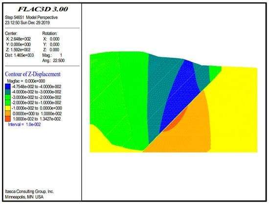
Figure 8.
Vertical (Z-direction) displacement contour.
Figure 9 shows the horizontal (X-direction) displacement cloud map of the goaf. The horizontal displacement in the X-direction of the goaf is developed to both sides; taking the positive center of the goaf as the dividing line, the left side of the center develops along the positive direction of X and the right side of the center develops along the negative direction of X. The displacement values on both sides are approximately mirror image changes, and the X-direction displacement development trend is in line with the deformation law of the underground deposit after excavation.
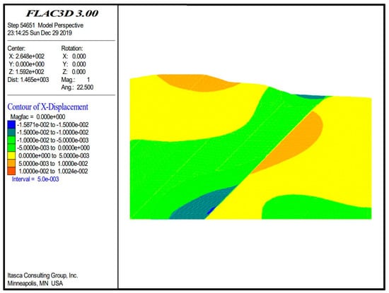
Figure 9.
Horizontal (X-direction) displacement contour.
Figure 10 shows the vertical stress cloud of the goaf, which is divided into two parts, with the range of stress variation increasing on the left and decreasing on the right. The vertical stresses in the Z-direction are all negative, and the vertical stresses in the Z-direction in the profile generally conform to the stress self-weight distribution, with the stresses gradually increasing from top to bottom.
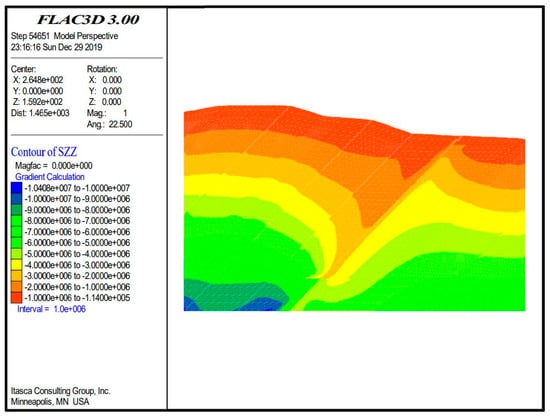
Figure 10.
Vertical stress contour.
Figure 11 shows the horizontal stress cloud of the goaf. The goaf is divided into two parts, with a certain pattern of horizontal stress distribution on the left that gradually increases from left to right, while the horizontal stress distribution on the right is more uniform. The horizontal stress in the X-direction of the section shows an irregular distribution.
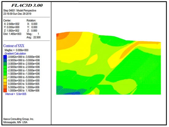
Figure 11.
Horizontal stress contour.
In summary, it can be seen from the displacement cloud diagrams that the vertical displacement of the goaf increases first and then decreases from left to right as the distance from the mining area decreases, while the horizontal displacement of the goaf develops to both sides. From the stress cloud diagrams, it can also be seen that the stress in the vertical direction of the goaf was divided into two parts, where the left side gradually increased and the right side gradually decreased due to the excavation of the coal seam forming the underground cavity, which broke the original stress balance; the stress of the overlying rock layer in the goaf was subsequently transferred to the periphery, creating a stress release area in the roof of the goaf. The stress in the horizontal direction gradually increased from left to right, mainly due to the excavation; the stress of the rock body was redistributed and the horizontal stress of the goaf roof slab was deflected in all directions. Therefore, displacement and stresses in the goaf lead to changes in the overlying rock.
- (2)
- Goaf Stability Analysis
Stress is redistributed after coal mining. Stress relaxation occurs in the roof rock mass of the goaf, and the upward stress on the roof of the goaf increases within a certain range. The stress and strain of the rock mass are approximately symmetrically distributed with the inclined coal seam as the boundary.
From the simulation calculation and analysis, the maximum displacement of the roof of the goaf was 4.797 cm; this area was located in the center of the mine, and the direction was biased to the direction of the goaf, while the displacement gradually decreased from the center to both sides. According to maximum tensile stress theory, the ratio of the tensile strength to the compressive strength of the coal mine was 0.04. Taking the compressive strength of the coal mine as 12.2 MPa, the tensile strength was calculated as 0.49 MPa. Taking a safety factor of 1.5 times, the rock mass of the allowable tensile strength was determined to be 0.33 MPa. During the simulation process, the stress changes on the roof of the goaf were monitored. As shown in Figure 12, it was found that the vertical stress changes above the roof of the goaf were all within the acceptable range of the rock mass. Figure 13 shows the horizontal stress. The maximum value of the change in horizontal stress exceeded the critical tensile strength of the rock, indicating that the roof of the goaf could no longer bear the change in rock mass stress.
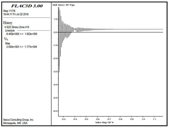
Figure 12.
Variation in vertical stress at a point above the roof of the goaf.
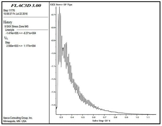
Figure 13.
Variation in horizontal stress at a point above the roof of the goaf.
As shown in Figure 14, under the influence of mining, the overlying strata in the goaf experienced displacement and deformation. According to the calculation and simulation results, the surface deformation in the goaf area had an obvious control effect on the depth of the goaf, in which the maximum vertical displacement was 4.5 cm and the maximum horizontal displacement was 1.5 cm.
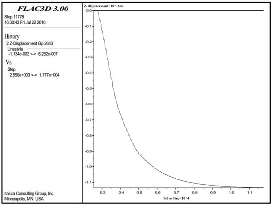
Figure 14.
Change in horizontal displacement of a point on the surface above the roof of the goaf.
In summary, using the FLAC(3D) finite difference method simulation calculation, it was concluded that the roof of the goaf and the overlying strata are in an unstable state. At the same time, this simulation only simulated the excavation process of the goaf and did not consider other factors, such as water filling in the goaf. As the water content in the goaf increases, the strength of the pillar will be greatly reduced as it is softened by the water, and the goaf will be in a more unstable state as a result. The simulation calculation results reflect the stress characteristics and deformation and failure laws of the coal mine goaf.
3.2. Comprehensive Evaluation and Restoration Design of Goaf Site in Garden Expo Park
3.2.1. Goaf Stability and Suitability Evaluation
- (1)
- Stability evaluation
The influence depth of the additional load of the new structure and the critical overburden thickness of the goaf are important indicators to determine the stability of goaf construction. The original equilibrium state of the caving fault zone is destroyed, and the overlying rock undergoes greater movement and deformation again. Generally, when the additional stress generated by the building load in the foundation is equal to 20% of the self-weight stress of the foundation at the corresponding depth, it can be considered that the influence of the additional stress on the foundation at that depth is negligible; however, when there is high compressibility soil below the building, or other unstable factors such as goaf slump and fracture zones, the additional stress should be calculated until the position of 10% of the weight stress of the foundation, at which point it can be considered that the additional stress does not have much influence on the foundation at this depth. This depth is the influence depth of the building (structure) load (H shadow). Here, a trial calculation was carried out according to the load of five-story and seven-story buildings. Table 5 lists the calculation results.
Table 5.
Building (5th, 7th floor) load influence depths.
The self-weight stress of the foundation was calculated using the following equation:
where represent the bulk density of each layer of soil or rock from top to bottom in the foundation (kN/m3) and denote the thickness of each layer of soil or rock from top to bottom in the foundation (m).
The average thickness of the quaternary topsoil in this area was determined as 2.5 m from the drilling results, and the bulk density was taken as 20 kN/m3 during calculation. The following bedrock strata were mainly sandstone, sandy mudstone, and shale, and the bulk density was taken as 26 kN/m3 for calculation.
The additional stress of the foundation was calculated as follows:
where is the vertical additional stress coefficients under various loads (rectangular, square, strip loads, etc.) and is the average additional pressure acting on the underside of the foundation (kN/m2), and
where P is the vertical uniform load at the bottom of the building (structure) foundation (kN/m2); is the bulk density of the natural soil layer above the base level, = 20 kN/m3; and is the embedded depth of the foundation (m).
After the coal seam is mined, and when the caving fault zone in the goaf is no longer moving due to the disturbance of the newly added building load, the minimum mining depth (Hm) should be greater than the height of the caving fault zone (Hc) and the impact depth of the building load (Hb), i.e., the sum of both.
Ha > Hm = Hc + Hb
The height of the stress concentration zone in the collapse fracture zone was generally 1.3 to 1.5 times the height of the fracture zone, and its value for this calculation was taken as 1.4.
Evaluation criteria: When the actual mining depth Ha < Hm, the foundation is unstable, and the overlying rock and the ground surface will move again with considerable unevenness. When the actual mining depth 1.4 Hc + Hb > Ha > Hm, the foundation is weakly stable and the overlying rock and the ground surface may move unevenly. When the actual mining depth Ha > 1.4 Hc + Hb, the foundation is stable and the building load will not cause the collapse fracture zone to move again.
Table 6 lists the stability conditions of the goaf in each region. From the theoretical calculation results alone, the burial depth of the goaf needs to be >90 m to be in a more stable state when considering the effect of a seven-story building load (about 20 m) within the goaf. However, the residual deformation effect caused by groundwater level lifting after the mining operation stopped and was not fully considered in the theoretical calculation; if the groundwater effect is considered, the burial depth of the goaf needs to be >120 m to be in a more stable state.
Table 6.
Evaluation form for building stability in goaf.
- (2)
- Suitability evaluation
According to the current survey, geophysical exploration, and drilling exposure (drilling depth of 110 to 150 m) during the work period, most of the early goafs in the survey area have collapsed to the surface and become stable. A small number of roadways and inclined shafts are semi-filled due to their small span; their crumbling and collapsing bodies are poorly compacted, and there is still considerable residual deformation and potential for geological hazards. According to the influence depth of the additional stress of the building foundation for multi-story buildings, combined with the critical thickness of the overburden layer in the upper part of the extraction area, the critical stability depth of the upper multi-story buildings was estimated to be around 90 to 100 m. Considering the early mining time in the evaluation area, the phenomenon of irregular mining, and the more complex underground excavation works, as well as the negative effects of pumping and draining groundwater and the sudden rise in groundwater level after mining was stopped—which aggravated residual deformation and ground collapse in the mining area—the thickness of the critical cover layer in the upper part of the mining area (depth of influence of building load + critical depth of the roof) was described by a safety factor of 1.3. We recommend that the horizontal projection of the surface in the area of the upper overburden of the mining area with a thickness of 120 m be taken as the boundary line of the deep part of the mining area, suitable for construction of multi-story buildings, and that the shallow part near the coal line be considered as the inner edge of the mobile basin with a safe construction distance of 25 to 30 m (taken in conjunction with the structure of the upper structure).
Using the assessment indexes in the Code for Geotechnical Engineering Investigation of Coal Mine Goaf and Code for Geological Investigation of Urban and Rural Planning Engineering, the site suitability of different sections in the evaluation area was divided according to the principle of building site suitability zoning into three major zones, as shown in Figure 15 and Table 7.
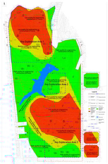
Figure 15.
Distribution of suitability evaluation areas.
Table 7.
Site engineering construction suitability rating and planning and design suggestions.
Poor suitability zone (Zone I): A region of poor suitability was found with an area of about 51 hectares, mainly concentrated in the southeast and north of the site. According to Technical specification for retaining and protection of building foundation excavations, this region is distributed over areas where the burial depth of the coal mine goaf is less than 100 m and those where the ground subsidence around the goaf is greater than 30 mm. A ground subsidence deformation greater than 30 mm around the foundation pit and site area has a considerable impact on buildings and structures; thus, it was designated as a poor suitability area.
Basic suitable area (Zone II): This region covers an area of about 24 hectares and is distributed where the depth of the goaf is 100 to 120 m and the land subsidence in the area around the goaf is between 10 to 30 mm. The land subsidence deformation has a certain influence on safe and normal use of ground buildings; thus, it was classified as a basic suitable area. In key exploration area 2, a small number of coal mining wellheads were investigated, and the goaf was not revealed after verification by three drilling holes. For the sake of safety, this region was also divided into the basic suitable area. In the distribution area of the No. 14 ore boundary in key exploration area 3, the existence of the coal mining wellhead was not found and the goaf was not revealed after verification by two drilling holes. To be cautious, it was also divided into the basic suitable area.
Suitability zones (Zone III): It includes the area distributed in the mining area depth greater than 120 m, the surrounding ground settlement less than 10 millimeters and the non-mining area. The ground deformation in the suitability zones has a slight impact on the safe use of ground buildings and structures.
3.2.2. Goaf Restoration Design
A landscape was created by relying on the existing landscape background, as shown in Figure 16, with water as the core and mountains as the backbone to form the spatial structure of “one axis and two zones”. According to the evaluation of site stability and the suitability of the goaf, the direction of its restoration should consider the matching social and economic systems while including the functions of culture, tourism, mass satisfaction, and aesthetic feeling, etc., with the aim of forming a systematic, complete, and referenceable ecological restoration model of the mining area.
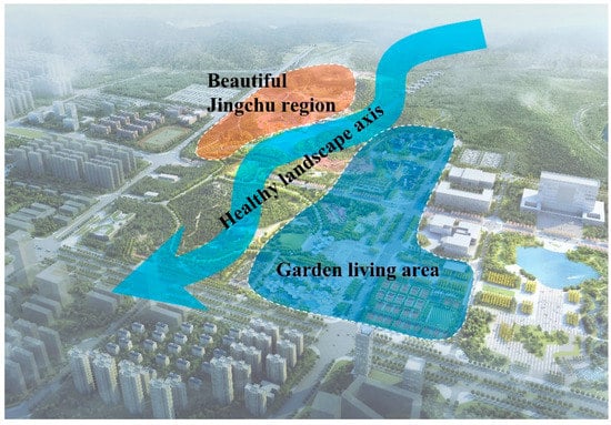
Figure 16.
Schematic diagram of the functional structure of the Garden Expo.
- (1)
- Poor Suitability Zone
- Quarry rehabilitation
Based on evaluation of the stability and suitability of the goaf of the Park Expo, as well as the land use status of the quarry after restoration, the intensity of manual intervention in restoration, and the ecological and social benefit characteristics of the restoration, three restoration methods can be applied: (1) the Park Expo construction model restores the quarry into an urban park green space with high ecological and social service value in a short period through higher manual intervention; (2) the ecological re-greening model takes appropriate artificial intervention measures to promote positive ecosystem succession over a certain period to restore the quarry into a green space with ecological value; and (3) the natural restoration model restores the ecosystem to a semi-nautral green space, without artificial interventions, over a long period. The three approaches were applied simultaneously to create the quarry garden in Figure 17.
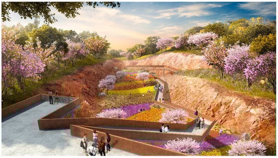
Figure 17.
Quarry Garden.
- Slope re-greening
In areas of poor suitability for water pipeline construction, slope re-greening can be utilized. In this method, the site is excavated to form a large, hardened pit land and create a valley of flowers. Lead enterprises can actively participate in the construction of the site and resource-based enterprises to commit to ecological construction (Figure 18). Here, the fact that vegetation root systems can reinforce, anchor, and contain water is used to enhance the stability of geotechnical slopes and provide certain ecological and landscape benefits.
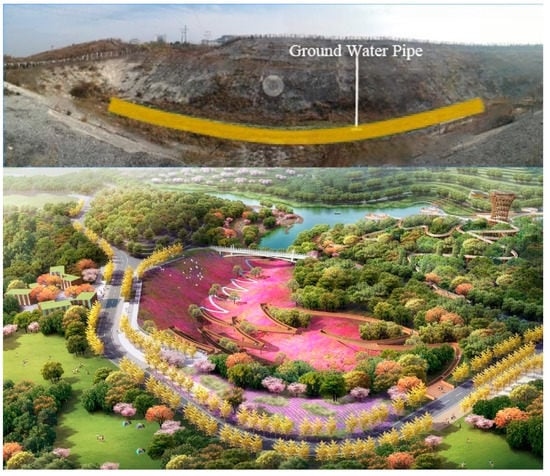
Figure 18.
Valley of nine flowers.
- (2)
- Basic Suitability Zone
In the basic suitable area, the Garden Expo Flower Street, as shown in Figure 19, can be built with assembled steel structures, which have strong seismic resistance. This method also takes into account the short construction period and provides a functional structure that can act as one of the core nodes in the park. At the same time, the hydrodynamic force can be restored and the original water in the base site will be allowed to move to complete the stacked cycle of water purification and create large fountains and other recreational facilities. Through cross-sections, the water permeability function of sponge materials and the water purification function of aquatic plants can be intuitively utilized to create a water purification garden, as shown in Figure 20. In the process of construction, it is necessary to consider the combination of infiltration and storage functions in the ecological purification function of plants. In order for water quality to reach the relevant standards, this type of rain garden can fully integrate the function of landscapes to achieve purification and filtration of rainwater.
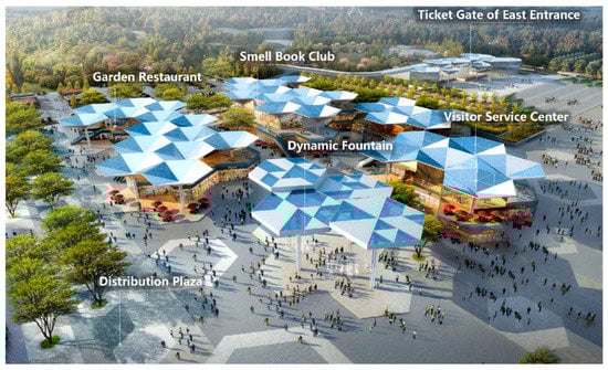
Figure 19.
Flower street.
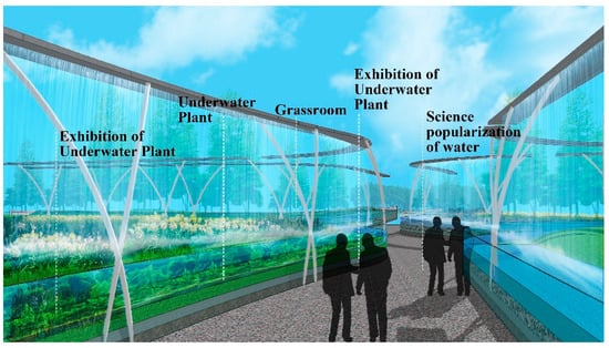
Figure 20.
Water purification garden.
- (3)
- Suitability Zone
The suitable area is stable, and construction at these sites is less harmful. Here, the iconic Jingmen Courtyard, as shown in Figure 21 and Figure 22, can be constructed. This structure will absorb the cultural genes of Guan Gong of the Three Kingdoms of the Duo Dao and draw lessons from the layout of the “Ninety-Nine Houses” of Jingmen residential buildings, with corridors and halls organizing the spatial sequence to create a new Chinese-style block that reflects the characteristics of Jingchu. Jingmen Courtyard will be close to municipal cultural facilities, with an excellent traffic location and a beautiful environment in the Garden Expo. It will be a display of folk customs and intangible cultural heritage during the garden exhibition and a garden hotel and creative workshop after the exhibition.
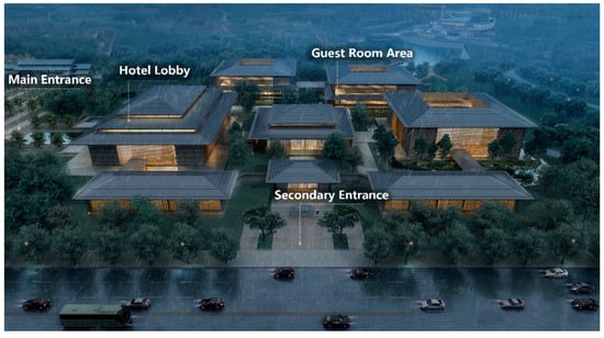
Figure 21.
Jingmen Courtyard north district garden hotel.
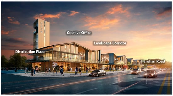
Figure 22.
Jingmen Courtyard south district creative workshop.
4. Discussion
In this study, we analyzed the stability and suitability of a coal mine goaf, taking the ecological problems of the typical area of Jingmen Garden Expo Park goaf as the research object, and investigated the planning and design theory and methods suitable for this goaf. We came to the following conclusions:
- (1)
- The caving and fissure zone analysis method and natural balance method were used in the stability analysis of the goaf, and the minimum and maximum thicknesses of the overlying rock mass in the three key exploration areas of the goaf due to the surrounding rock pressure were obtained: these values were 40.19 m and 48.33 m in key exploration area 1; 36.45 m and 44.24 m in key exploration area 2; and 49.77 m and 57.57 m in key exploration area 3, respectively.
- (2)
- A numerical model of the mobile deformation of the mining area was established, and its profile stress and displacement were analyzed using FLAC(3D) finite difference method simulation calculation. The results of profile stress analysis showed a tensile strength of 0.49 MPa, while the allowable tensile strength of the rock was 0.33 MPa. The results of displacement analysis showed that the maximum vertical displacement was 4.5 cm and the maximum horizontal displacement was 1.5 cm. In summary, the top plate of the mining area and the overlying rock are in an unstable state.
- (3)
- According to the calculation results, the suitability of the site was evaluated and the site was divided into three categories—poor suitability zone, basic suitability zone, and suitability zone—for which different ecological restoration plans were proposed.
In practice, the positioning and design of the functional structure inside the goaf cannot be ignored. Therefore, how to combine the internal spatial structure and function of the goaf with the surrounding area will be the focus of further exploration and research. In addition, when creating the ecological spatial structure of “one axis and two districts”, the analysis and evaluation methods and design schemes selected in this study largely depend on the experience of planners and the opinions of local authorities.
5. Conclusions
In this study, we analyzed the deformation mechanism and stability theory of a goaf, established a numerical model of the mining area, carried out a stability evaluation and building site suitability evaluation of the area, and finally proposed an ecological restoration plan for areas with different suitability according to the stability analysis results. Following the restoration practice of the stability calculation of the goaf in Garden Expo Park, it was shown that the planning path and the technical methods of the different stages proposed in this paper are feasible. A well-thought-out restoration of the mining area with respect to economic and social aspects will lay a solid foundation for global green and sustainable development.
Author Contributions
Conceptualization, methodology, data curation, and writing—original draft, Z.X. Methodology, data curation, and funding acquisition, W.X. Conceptualization, methodology, data curation, writing—original draft, and supervision, P.Z. and Z.Z. Methodology and writing—original draft, J.Z. Writing—review and editing, P.G. All authors have read and agreed to the published version of the manuscript.
Funding
This research was funded by the 2021 Hubei Provincial Construction Science and Technology Plan Project (Item No. 63).
Institutional Review Board Statement
Not applicable.
Informed Consent Statement
Not applicable.
Data Availability Statement
Data can be obtained from the corresponding author if necessary.
Conflicts of Interest
The authors declare no conflict of interest.
References
- Yu, D.; Xun, B.; Shi, P.; Shao, H.; Liu, Y. Ecological restoration planning based on connectivity in an urban area. Ecol. Eng. 2012, 46, 24–33. [Google Scholar] [CrossRef]
- Pierce, A.L.; Heyder, M.; Tregonning, G.; Laborgne, P.; Wilhelmi, O.; Wendel, J. Examining knowledge of the nexus at the urban scale. In Handbook on the Water-Energy-Food Nexus; Edward Elgar Publishing: Cheltenham, UK, 2022; pp. 193–209. [Google Scholar]
- Huang, B.; Xing, K.; Ness, D.; Liao, L.; Huang, K.; Xie, P.; Huang, J. Rethinking carbon–neutral built environment: Urban dynamics and scenario analysis. Energy Build. 2022, 255, 111672. [Google Scholar] [CrossRef]
- Lyu, X.; Yang, K.; Fang, J. Utilization of resources in abandoned coal mines for carbon neutrality. Sci. Total Environ. 2022, 822, 153646. [Google Scholar] [CrossRef]
- Wang, F.; Zhu, H.; Li, Y.; Gu, D.; Gao, Y.; Feng, J.; Shu, B.; Li, C.; Wu, S.; Liu, Q. Microwave heating mechanism and Self-healing performance of scrap tire pyrolysis carbon black modified bitumen. Constr. Build. Mater. 2022, 341, 127873. [Google Scholar] [CrossRef]
- Aung, T.S.; Fischer, T.B.; Shengji, L. Evaluating environmental impact assessment (EIA) in the countries along the belt and road initiatives: System effectiveness and the compatibility with the Chinese EIA. Environ. Impact Assess. Rev. 2020, 81, 106361. [Google Scholar] [CrossRef]
- Asr, E.T.; Kakaie, R.; Ataei, M.; Mohammadi, M.R.T. A review of studies on sustainable development in mining life cycle. J. Clean. Prod. 2019, 229, 213–231. [Google Scholar] [CrossRef]
- Li, J.; Lin, B. Landscape planning of stone mine park under the concept of ecological environment restoration. Arab. J. Geosci. 2022, 15, 671. [Google Scholar] [CrossRef]
- Tong, L.; Liu, L.; Qiu, Y.; Liu, S. Tunneling in abandoned coal mine areas: Problems, impacts and protection measures. Tunn. Undergr. Space Technol. 2013, 38, 409–422. [Google Scholar] [CrossRef]
- Yin, Z.; Feng, D. Landscape planning and design of Zhanggongdi City Park based on human ecology. IOP Conf. Ser. Earth Environ. Sci. 2021, 760, 012057. [Google Scholar] [CrossRef]
- Heesche, J.; Braae, E.M.; Jørgensen, G. Landscape-Based Transformation of Young Industrial Landscapes. Land 2022, 11, 908. [Google Scholar] [CrossRef]
- Wu, C.; Zhang, Y.; Zhang, J.; Chen, Y.; Duan, C.; Qi, J.; Cheng, Z.; Pan, Z. Comprehensive Evaluation of the Eco-Geological Environment in the Concentrated Mining Area of Mineral Resources. Sustainability 2022, 14, 6808. [Google Scholar] [CrossRef]
- Bogdanov, V.; Marquis-Favre, C.; Cottet, M.; Beffara, B.; Perrin, F.; Dumortier, D.; Ellermeier, W. Nature and the City: Audiovisual interactions in pleasantness and psychophysiological reactions. Appl. Acoust. 2022, 193, 108762. [Google Scholar] [CrossRef]
- Vujcic, M.; Tomicevic-Dubljevic, J.; Grbic, M.; Lecic-Tosevski, D.; Vukovic, O.; Toskovic, O. Nature based solution for improving mental health and well-being in urban areas. Environ. Res. 2017, 158, 385–392. [Google Scholar] [CrossRef]
- Li, W.; Zhang, S.; Lu, C. Exploration of China’s net CO2 emissions evolutionary pathways by 2060 in the context of carbon neutrality. Sci. Total Environ. 2022, 831, 154909. [Google Scholar] [CrossRef]
- Shu-Zhi, L.I. Present Status and Outlook on Land Damage and Reclamation Technology of Mining Subsidence Area in China. Coal Sci. Technol. 2014, 1, 93–97. [Google Scholar]
- Farina, A. Human-Dependent Landscapes around the World—An Ecological Perspective. In Principles and Methods in Landscape Ecology; Springer: Berlin/Heidelberg, Germany, 2022; pp. 339–399. [Google Scholar]
- Wu, J.; Zhang, S.; Luo, Y.; Wang, H.; Zhao, Y. Assessment of risks to habitat connectivity through the stepping-stone theory: A case study from Shenzhen, China. Urban For. Urban Green. 2022, 71, 127532. [Google Scholar] [CrossRef]
- Jain, M.K.; Das, A. Impact of mine waste leachates on aquatic environment: A review. Curr. Pollut. Rep. 2017, 3, 31–37. [Google Scholar] [CrossRef]
- Jouini, M.; Royer-Lavallée, A.; Pabst, T.; Chung, E.; Kim, R.; Cheong, Y.-W.; Neculita, C.M. Sustainable Production of Rare Earth Elements from Mine Waste and Geoethics. Minerals 2022, 12, 809. [Google Scholar] [CrossRef]
- Chen, C. Research on the Recycling Utilization of Mining Wasteland-Comment on “Surface Space Ecological Development and Key Technology of Mining Wasteland”. Min. Res. Dev. 2020, 40, 193. [Google Scholar]
- Venkateswarlu, K.; Nirola, R.; Kuppusamy, S.; Thavamani, P.; Naidu, R.; Megharaj, M. Abandoned metalliferous mines: Ecological impacts and potential approaches for reclamation. Rev. Environ. Sci. Bio/Technol. 2016, 15, 327–354. [Google Scholar] [CrossRef]
- Farjana, S.H.; Huda, N.; Mahmud, M.P.; Saidur, R. A review on the impact of mining and mineral processing industries through life cycle assessment. J. Clean. Prod. 2019, 231, 1200–1217. [Google Scholar] [CrossRef]
- China Coal Construction Association. Code for Investigation of Geotechnical Engineering in the Coal Mine Goaf; China Plan Publishing House: Beijing, China, 2017. [Google Scholar]
- Chen, J.; Xu, C.; Wang, Y.; Li, D.; Song, M. Carbon neutrality based on vegetation carbon sequestration for China’s cities and counties: Trend, inequality and driver. Resour. Policy 2021, 74, 102403. [Google Scholar] [CrossRef]
- Muthusaravanan, S.; Sivarajasekar, N.; Vivek, J.; Paramasivan, T.; Naushad, M.; Prakashmaran, J.; Gayathri, V.; Al-Duaij, O.K. Phytoremediation of heavy metals: Mechanisms, methods and enhancements. Environ. Chem. Lett. 2018, 16, 1339–1359. [Google Scholar] [CrossRef]
- Qiu, Z.; Feng, Z.; Song, Y.; Li, M.; Zhang, P. Carbon sequestration potential of forest vegetation in China from 2003 to 2050: Predicting forest vegetation growth based on climate and the environment. J. Clean. Prod. 2020, 252, 119715. [Google Scholar] [CrossRef]
- Shi, C. Engineering Geology Handbook, 5th ed.; China Construction Industry Press: Beijing, China, 2018. [Google Scholar]
- Feng, X.; Liu, G.; Chen, J.; Chen, M.; Liu, J.; Ju, W.; Sun, R.; Zhou, W. Net primary productivity of China’s terrestrial ecosystems from a process model driven by remote sensing. J. Environ. Manag. 2007, 85, 563–573. [Google Scholar] [CrossRef]
- Arnberger, A.; Eder, R. Are urban visitors’ general preferences for green-spaces similar to their preferences when seeking stress relief? Urban For. Urban Green. 2015, 14, 872–882. [Google Scholar] [CrossRef]
- Chen, C.L.; Zhang, H. Do You Live Happily? Exploring the Impact of Physical Environment on Residents’ Sense of Happiness. IOP Conf. Ser. Earth Environ. Sci. 2018, 112, 012012. [Google Scholar] [CrossRef]
- Danya, K.; Jin, J. Does happiness data say urban parks are worth it? Landsc. Urban Plan. 2018, 178, 1–11. [Google Scholar]
- Huang, X.; Wang, H.; Shan, L.; Xiao, F. Constructing and optimizing urban ecological network in the context of rapid urbanization for improving landscape connectivity. Ecol. Indic. 2021, 132, 108319. [Google Scholar] [CrossRef]
- Li, A.; Zheng, H. Energy security and sustainable design of urban systems based on ecological network analysis. Ecol. Indic. 2021, 129, 107903. [Google Scholar] [CrossRef]
- Hong, X.; Liu, J.; Wang, G.; Jiang, Y.; Wu, S.; Lan, S. Factors influencing the harmonious degree of soundscapes in urban forests: A comparison of broad-leaved and coniferous forests. Urban For. Urban Green. 2019, 39, 18–25. [Google Scholar] [CrossRef]
Disclaimer/Publisher’s Note: The statements, opinions and data contained in all publications are solely those of the individual author(s) and contributor(s) and not of MDPI and/or the editor(s). MDPI and/or the editor(s) disclaim responsibility for any injury to people or property resulting from any ideas, methods, instructions or products referred to in the content. |
© 2023 by the authors. Licensee MDPI, Basel, Switzerland. This article is an open access article distributed under the terms and conditions of the Creative Commons Attribution (CC BY) license (https://creativecommons.org/licenses/by/4.0/).