Article

Influence of Base-Angle Bolt Support Parameters and Different Sections on Overall Stability of a Roadway under a Deeply Buried High Stress Environment Based on Numerical Simulation

1
Deep Mining Laboratory, Shandong Gold Group Co., Ltd., Yantai 261400, China
2
School of Resource Environment and Safety Engineering, University of South China, Hengyang 421001, China
*
Author to whom correspondence should be addressed.
Sustainability 2023, 15(3), 2496; https://doi.org/10.3390/su15032496
Submission received: 1 November 2022 / Revised: 21 January 2023 / Accepted: 24 January 2023 / Published: 30 January 2023
(This article belongs to the Special Issue Challenges and Strategies for Sustainable Development in Deep Mines)

Abstract

:
Strengthening the base-angle of a roadway can have a beneficial impact on its overall stability, but the specific optimal parameter selection range is still unclear. Fast Lagrangian Analysis of Continua 3D (FLAC3D) software is used to carry out the stability analysis of 5 kinds of roadway models with different section shapes under the conditions of no support and different base-angle bolt support angles, and the simulation verification is carried out under the actual working conditions of the Sanshandao Gold Mine. The conclusion is as follows: without support, the self-stability of a tri-centric arch roadway is the best, and that of a rectangular roadway is the worst. When the base-angle bolt dip angle is between 15° and 45°, a better supporting effect can be obtained under the established 5 kinds of roadway sections. In the straight wall circular arch roadway of the Sanshandao Gold Mine, the roadway stability is the best when the angle of the base-angle bolt is 15°. However, changing the length of the base-angle bolt, even if the length of the base-angle bolt is increased to a certain extent, will decrease the overall supporting effect of the supporting structure. This paper can provide a reference for the selection of tunnel bottom corner bolt support parameters.

1. Introduction

With the gradual depletion of shallow resources, an inexorable trend of exploiting deep minerals has developed; worldwide, there are already more than 100 mines operating at depths greater than 1000 m [1]. After entering the deep area, the roadway environment is more complex, and the complex environment of three “high” and one “disturbance” puts forward higher requirements for roadway support. Controlling the convergence of surrounding rock and the failure of base-angle area is the key to the support of a deep roadway. Compared with the roadway roof, the importance of its sidewall and floor is often ignored [2]. The base-angle area of the roadway is an easy location to concentrate force, but it breaks the region near the base-angle area, which has a negative impact on the stability of the overall roadway.
To solve the above problems, some experts and scholars have studied the support problem of the base-angle area of the roadway. For example, Shan Ren liang and other experts [3,4] first studied the support effect under different support schemes made up of soft and broken surrounding rock coal through numerical simulation, and the “strong sidewall and corner support control technology” was proposed. It was determined that this method could effectively control the deformation of a soft and broken surrounding rock coal lane. In addition, they verified the effectiveness of “strong angle support technology” through similar simulation experiments. At the same time, a detailed numerical simulation scheme was developed to study the role of each parameter of the gang bolt in the “strong sidewall and corner support control technology.” By carrying out similar physical tests, Kong et al. [5] deeply analyzed the effect of strong side and strong angle support, suggesting the three-step design method of coal roadway support, and found that the damage of coal roadway mainly occurred at the side and corner. Zhen et al. [6], through similar simulations and industrial tests, verified the effectiveness of a strong angle support technique in the empty lane, and obtained good results in the application of the empty lane. Moreover, they determined that it can fully mobilize the carrying capacity of the deep surrounding rock by enhancing the strength of the support and the corner support to achieve the purpose of improving the stress state of the surrounding rock. By means of 3D numerical simulation, Yang et al. [7] demonstrated the important role of the base-angle bolt in the control of the bottom drum, and the working mechanism of the control bottom and the design method of the asymmetric bottom bolt were put forward. Yang et al. [8] established the mechanical analysis model of the tunnel bottom drum according to the bolt and the mechanical analysis of the action mechanism of the bottom drum controlled by the base-angle area bolt. Meanwhile, they determined the most suitable type of tunnel bottom shaft through an indoor experiment, achieving good results in the actual engineering application. Liang et al. [9] analyzed the principle of a base-angle area bolt bar control bottom drum, and the feasibility of inhibiting the floor deformation was verified by FLAC3D numerical simulation software. In addition, the cyclic impact load generated by roadway mining will also accelerate the fragmentation of the base-angle area and other locations, increasing the difficulty of support in this area. Dai et al. [10,11,12,13] studied the mechanical and energy dissipation characteristics of granite under a cyclic impact load, providing a theoretical basis for base-angle area support from the mechanical and energy perspectives. Moreover, Krykovskyi et al. [14] carried out research on the strengthening effect of grouting the rock bolt onto weak surrounding rock, which enriched the strengthening theory of bolt support. Dyczko et al. [15] verified the importance of the roof bolt and applied it to engineering practice to carry out relevant monitoring. Małkowski et al. [16] evaluated the stability of the roadway using five different techniques and continuous monitoring for six years, based on the premise of large-scale rock mass and support monitoring. Ratan et al. [17] used a numerical method based on the finite element code to determine the influence of different bolt lengths and diameters on the maximum induced boundary displacement in jointed rock mass. It was determined that the increase in bolt length did not significantly reduce the boundary displacement, while the increase in bolt diameter significantly reduced the tunnel boundary displacement. Gabriel et al. [18] presented the results of roadway response and support performance monitoring in two longwall mines at 180m and 600m cover depths, demonstrating the potential of numerical models to help mine engineers optimize longwall layout and roadway support systems.
At present, there is no research on the optimal supporting parameters of the base-angle bolt under different roadway section shapes, and there are few studies on the dip angle and length of the base-angle bolt; therefore, to solve the above problems, based on FLAC3D, this paper analyses the support effect of different base-angle bolt inclined angles for five typical cross-sectional profiles of the roadway, The optimal slope range of the base-angle bolt, with high applicability, was obtained, verifying the influence of the base-angle bolt inclined angle and the base-angle bolt length on the overall stability of the roadway using the deep roadway in the Xishan area of the Sanshandao gold mine as an example. This study can provide a reference for the design of a roadway support scheme, including the selection of parameters such as roadway section, dip angle, and length of base-angle bolt, illustrating the beneficial effect of "strong side and strong angle" on the overall stability of a roadway.

2. Mechanism of Action of Base-Angle Bolt

2.1. Bolting Mechanism of the Base-Angle Bolt

The bolt anchoring mechanism refers to using an anchoring agent that will bond to form a whole anchor rod body with the surrounding rock, improving the mechanical parameters of the surrounding rock near the tunnel. During excavation, roadway cross-section contour deformation occurs, and the nearby surrounding rock stress redistributes, affording bolt stress, and the load transfer to the stability of the deep strata, which hinders the continuous deformation of the rock mass. At present, there is both macroscopic and microscopic research on the anchorage mechanism of the bolt. Macroscopically, the main research direction is the change law of mechanical parameters and the bearing capacity of solid anchor after reinforcement. The main research direction at the micro level is the distribution characteristics of bolt axial force and shear stress at anchorage interface [19].
When the two sides of the bolt are parallel to the horizontal line, the anchorage area is mainly distributed in the two sides, and the surrounding rock of the floor has not been significantly improved, which can easily produce floor heave. The bolt applied to the base-angle area can strengthen the floor and give a certain degree of support to the floor, controlling the floor heave and improving the overall stability of the roadway. The bolt-reinforced surrounding rock is shown in Figure 1.

2.2. Current Status of Base-Angle Bolt Applications in the China

According to the statistics in the literature regarding roadway support optimization in China over the last two years, it is noted that only a few mines use base-angle bolt applications for support, and most mines do not strengthen the support of the base-angle area, and more than half of the roadways have deflected the bolts at the floor of the two sidewalls, with the angle mainly concentrated between 5° and 30°, as shown in Table 1. Common base-angle bolt support inclined angles are: 0°,10°,15°,25°, and 30°, of which 15° is the most widely used [20]. Currently, there is no unified understanding and theoretical support for the selection of the inclined angle of the base-angle bolt, and often only approximate parameters are selected, based on engineering experience. It is important to obtain a base-angle bolt support inclined angle that is suitable for most of the roadway, which will improve the stability of the roadway floor without increasing the bolt density and without reducing the support strength of the sidewall.

3. Numerical Simulation Study of Different Cross-Sectional Roadway Profiles

FLAC is a numerical simulation software developed by ITASCA. FLAC3D [30,31] is an extension of the two-dimensional finite difference program FLAC2D; it adopts explicit Lagrangian algorithm and mixed-discrete partitioning technology, which can simulate the plastic failure and flow of materials very accurately. It can simulate the mechanical properties and analyze the plastic flow of soil, rock, and other materials. Meanwhile, FLAC3D has the characteristics of fast and accurate calculation, along with a wide application range, and has been widely used in geotechnical engineering analysis [32].

3.1. Model Construction

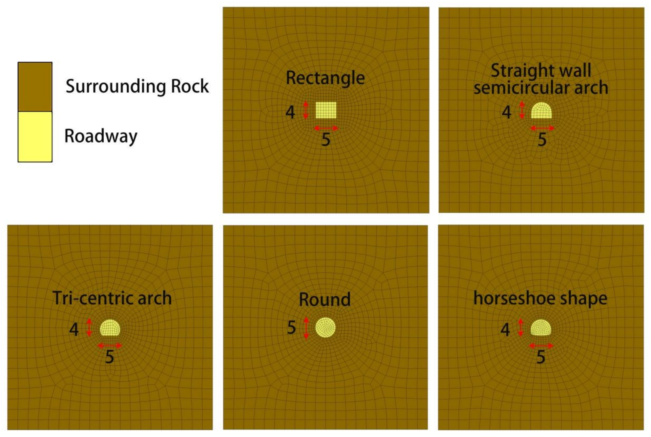
Rhino modeling software was used to construct five types of roadway models: rectangle, horseshoe shaped, tri-centric arch, straight wall, and semi-circular arch; finally, FLAC3D mesh files were generated through the Griddle plug-in. The model size is 50 × 50 × 5.5 m, and the area near the roadway is encrypted to enhance the calculation accuracy near the tunnel [33]. The combination of the Mohr circle and the Coulomb envelope forms the Mohr–Coulomb (M-C) failure criterion [34,35,36], which is a set of linear equations describing the failure conditions of isotropic materials in the principal stress space, and which is widely used to solve various engineering problems as a standard for determining the failure of rock materials. Thus, the Mohr–Coulomb model is selected for this structure model, and after the model is built, the boundary constraints are applied so that the front, rear, and bottom boundary displacements are 0. The roof of the model is not constrained, and the gravitational acceleration is set to 9.81 m/s2; considering the effect of geostress, apply stress to the model to generate the initial stress field, and the constructive stress coefficient is taken as 1.0, the size is taken as 40 MPa, and the model calculation parameters are shown in Table 2. At present, scholars have carried out corresponding studies on the shape of roadway sections [37,38,39]. Referring to the above studies and the general types of mine roadway section shapes in China, five kinds of roadway models have been established; the numerical model of five kinds of roadways is shown in Figure 2 (hereafter referred to as Rec, Swsa, Tca, Rou, and Hs); they have the same length and width (5 × 4 m) to reduce interference from other factors.

3.2. Program Design

To find the best inclined angle for the base-angle bolt, 7 base-angle bolt angle solutions were designed for each cross-sectional profile, for a total of 35 sets of solutions. The length of the bolt was 2.2 m, the distance between rows was 0.9 × 0.9m, and the distance from the front and rear surfaces of the model was 0.5m. The inclined angle of the base-angle bolt support differed by 15° for each scheme to selectively enhance the effect of the bolt support so that the law of observation could be easily detected, and the specific schemes are shown in Table 3.

3.3. Simulation Results

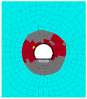
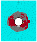
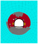
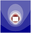
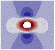
The cloud diagram of the roadway surrounding rock plastic zone, displacement, vertical stress, and horizontal displacement without support is shown in Table 4. Under the conditions set by the experimental scheme, the existing plastic zone of the roadway surrounding rock, with all cross-sectional profile shapes, is the shear failure plastic zone, and these zones are mainly concentrated on both sides of the roadway. The displacement in the corner of the roadway cross-sectional profile shape is less than that in other areas of the sectional contour (roof, floor, sidewall); the distribution law of a mining stress field is roughly the same in a roadway with different cross-sectional profile shapes. Due to the excavation of the roadway, the cavitation surface is formed, and the stress is redistributed, which leads to the reduction of stress in the area near the roadway, and more stress is transferred to the deep area.
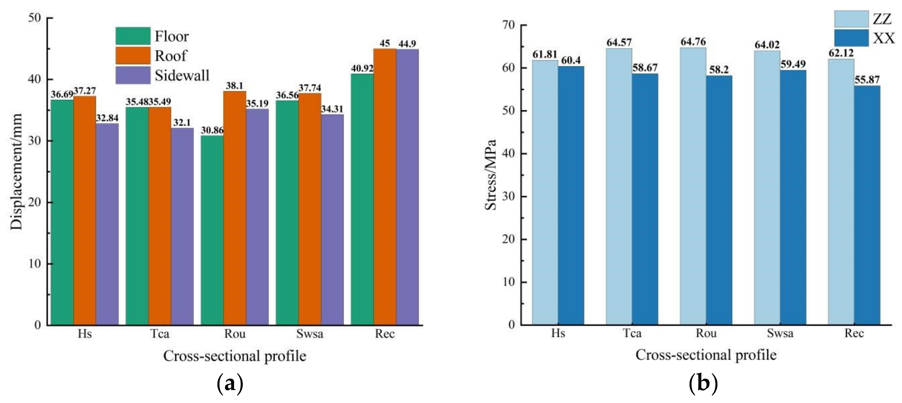
Figure 3 shows the maximum displacement and maximum stress parameters of the roadway when excavation is carried out for five designs using cross-sectional profile, without support. In the relationship between the size of the sidewall and the floor, different sections have different patterns. Unlike the other four sections, the displacement of the sidewall part in the rectangular roadway is very close to the roof displacement, and the horizontal displacement control effect of this cross-sectional profile is weak.
With the excavation of the roadway, the stresses are redistributed and the stresses around the roadway are reduced, forming a stress relaxation zone, and most of the stresses are transferred to a deeper area. The vertical and horizontal stresses in the stress concentration area increase from 40 MPa to over 60 MPa and 55 MPa, with the most significant effect of vertical stress concentration in circular roadways, and the most significant effect of horizontal stress concentration in horseshoe-shaped roadways. In a comprehensive view, the concentration effect of vertical stresses is generally greater than that of horizontal stresses, the mining unloading effect of rectangular roadways is the weakest, and the unloading effect of horseshoe-shaped roadways on each vertical and horizontal stress is more uniform.
The displacements of the five designed cross-sectional profiles of the roadway under different inclined angles for base-angle bolt support schemes are shown in Figure 4. Where (a–c), respectively, represent the displacement changes in the floor, roof, and sidewall parts under five different section shapes and different base-angle bolt inclination angles. With the increase in the angle between the base-angle bolt and the horizontal plane, the displacement at different positions of the roadway presents a general evolution law, that is, “increase first and then decrease”. Among them, the displacement of the horseshoe shape, tri-centric arch, and the circular roadway is more obvious, while the displacement of the straight wall semicircle arch and rectangular roadway is less significant, but it can still be observed that the minimum value of overall displacement is mainly concentrated in the base-angle bolt of the angle anchor between 15°~45°. It is worth noting that the displacement of the roof and the sides of the horseshoe shaped roadway decreases significantly when the angle is 45°.
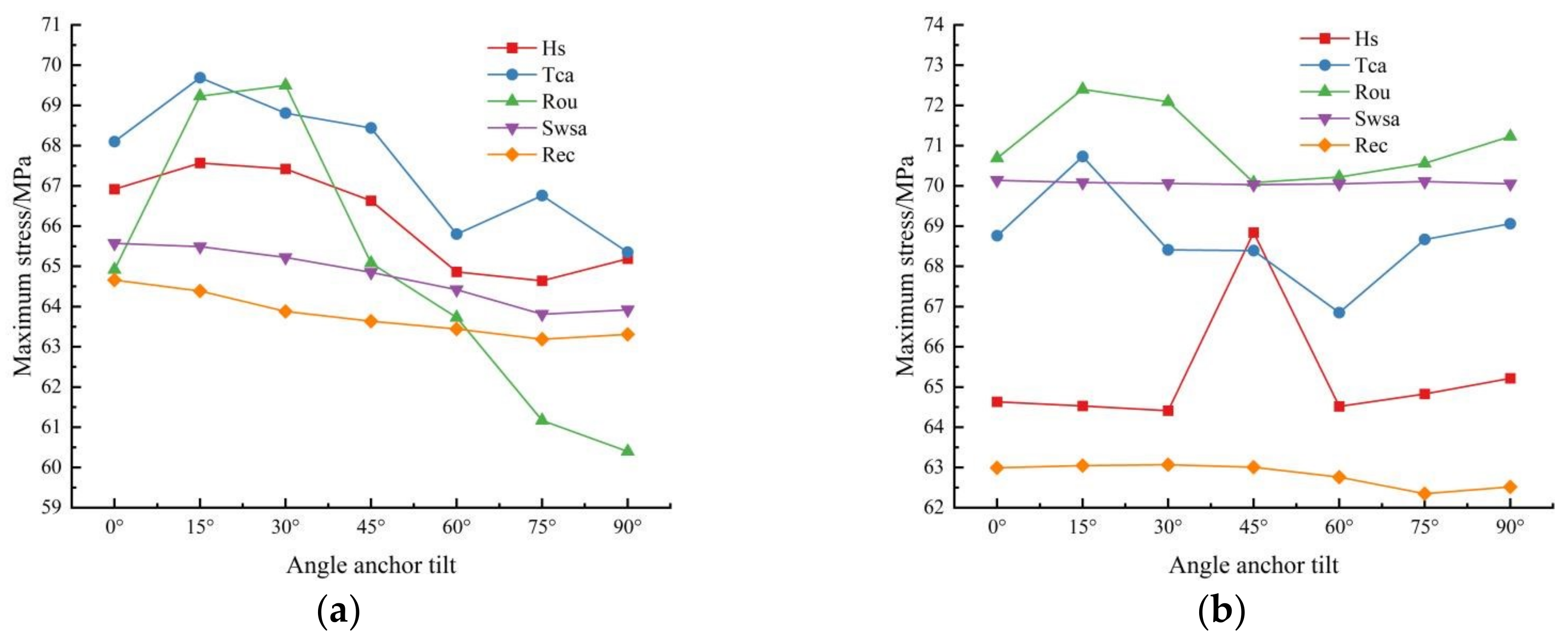
As shown in Figure 5, the maximum stress variation and maximum displacement variation patterns of the five designs of the cross-sectional profile of the roadway under different inclined angles of the base-angle bolt support schemes remain basically the same. When more stress is concentrated in the deeper part of the roadway, the better the unloading effect near the roadway section, which in turn is reflected in the smaller maximum displacement of the roadway, which reflects the constitutive model link between stress variation and displacement manifestation.
The stability of the roadway is controlled by all parts of the roadway, resulting in a whole in which each part affects the other and works together. When the support of one part is neglected, the displacement of other parts will increase, which will affect the stability of the whole roadway. From the above analysis, a bolt angle of around 15° to 45° can achieve good support in most cross-sectional profiles of the roadway.

4. Numerical Simulation Study of Engineering Examples

4.1. Overview of Roadway

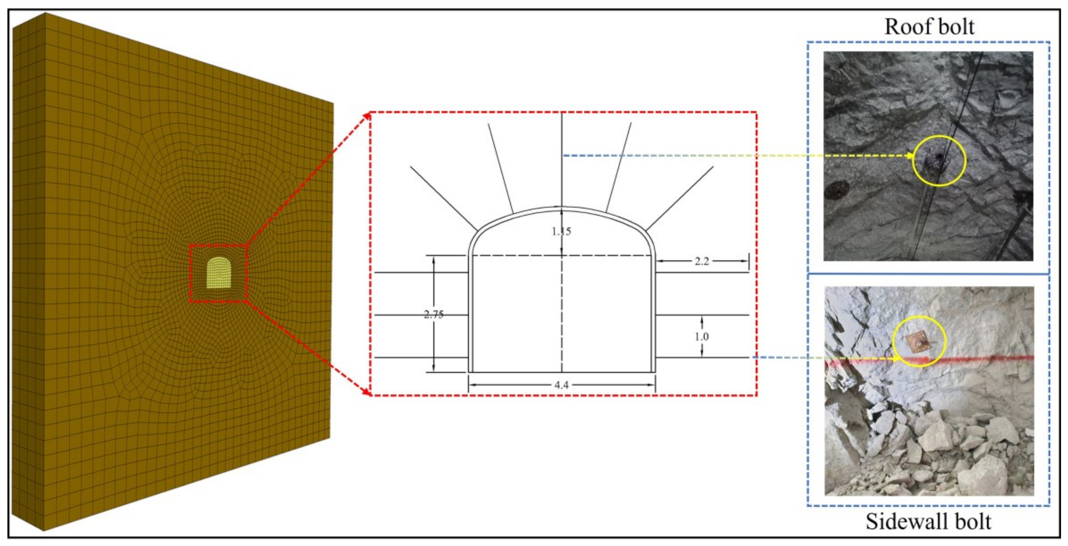
Based on the above research, this paper optimizes the parameters of base-angle bolt support for the base-angle area of the north lane of section 945 in the west mountain mining area of the Sanshandao gold mine, where the cross-sectional profile shape of the roadway is Swsa, with a span of 4.4m, two sidewall heights of 2.75 m, and an arch height of 1.15 m. The row distance is 1m×1m, shotcrete is the material for the M20 mortar, and the thickness is 100mm; the specific support design is shown in Figure 6. The simulation focuses on the impact of the bolt effect, so ignore the impact of the concrete spray layer. The area of the roadway buried depth is large, and it has been in a high stress state. According to the field measurement results, 945 m buried channel deep ground stress of 31.0 MPa~44.1 MPa; for this simulation of structural stress coefficient to take 1.0, vertical stress = horizontal stress = 44.1 MPa; the physical and mechanical parameters of the surrounding rock are shown in Table 5.

4.2. Model Construction

A grid model with a specification of 50 × 50 × 6 m (width × height × length) was created, and the grid near the roadway was encrypted with 34,884 zones and 26,793 nodes. After the model was established, displacement constraints were applied to the front and rear surfaces, left and right surfaces, and lower surfaces of the model, and the top of the model was a free surface. Considering the influence of gravity, the gravitational acceleration of the model is set as 9.81 m/s2. The in situ stress was applied to the model to generate the initial stress field. The structural stress coefficient was set at 1.0; that is, the horizontal stress and vertical stress were both set at 44 MPa. The section shape and parameters of the roadway were the same as the actual conditions of the roadway above, and the roadway model with the initial stress field cloud is shown in Figure 7.

4.3. Program Design

Through the above research, the optimal support dip angle range of base-angle bolt under various section shapes is obtained, but the parameters used are not the section shapes and specifications of the actual engineering. Therefore, taking the Sanshandao Gold Mine as an example, the subsequent simulation is completed by comparing the displacement size of the roadway, without support, under three constitutive models and selecting a constitutive model more suitable for actual engineering. In order to provide a more comprehensive reference for the base-angle bolt support design, the parameter of bolt length is added, while verifying the optimal range of the base-angle bolt support angle.
The elastic model, Mohr–Coulomb model, and softening Mohr–Coulomb model were chosen for the calculations, with the softening Mohr–Coulomb coefficients shown in Table 6 and Figure 8. The displacements were 7.05 mm for the elastic constitutive model, 18.80 mm for the Mohr–Coulomb constitutive model, and 33.78 mm for the softening Mohr–Coulomb model, with a similar distribution of displacements in the sidewall, roof, and floor of the roadway. Compared with the other two models, the internal friction angle, cohesion, and shear expansion angle of the softening Mohr–Coulomb model decrease with increasing shear strain, which is more in line with the deterioration process of the roadway envelope during the actual excavation of the area.
The softening Mohr–Coulomb model is used as the constitutive model to adjust the base-angle bolt at the sidewall of the roadway, and inclined angles for four base-angle bolts of 0°, 15°, 30°, and 45° are designed. The optimum inclined angle is obtained after comprehensive analysis, and the length of the base-angle bolt under the optimum inclined angle is changed, as shown in Table 7.

4.4. Simulation Results and Analysis

4.4.1. Angle

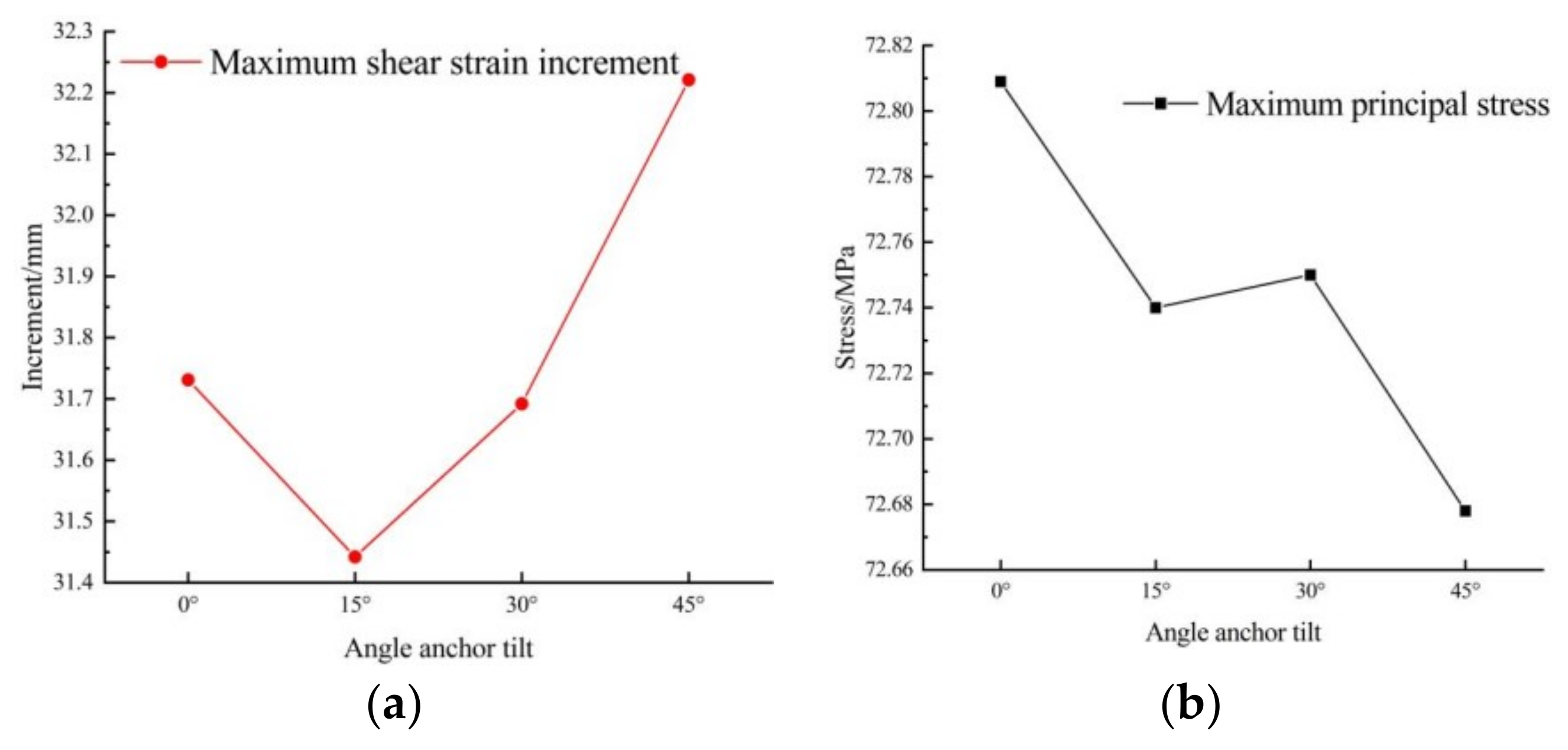
The roadway displacements at different bolt inclined angles are shown in Figure 9, with the roof and floor plate showing a decreasing trend with the increasing inclined angle, the roof leveling off in the region after reaching 45°, and the sidewall showing an increasing and then decreasing trend, reaching the lowest point at 15°. The shear strain increment and the maximum principal stress are shown in Figure 10, the shear strain increment is the smallest at 15°, the maximum principal stress first decreases and then increases and decreases again, and the size order is: 0° > 30° > 15° > 45°. The maximum principal stress first decreases, and then decreases again, in the following order: 0° > 30° > 15° > 45°. Considering all these factors, a good overall support effect can be obtained at an angle of 15°.
The displacement, maximum principal stress, and maximum shear stress under the floor of each scheme were monitored, and the change curve is shown in Figure 11. Displacement is intrinsically related to stress, and the displacement tends to flatten out after 3 m, while the maximum principal stress and maximum shear stress are concentrated at 3 m. The stresses show a trend of increasing first and then decreasing, and the maximum principal stress appears obvious in the stress relaxation zone, the stress concentration zone, and original rock stress zone. After about 7.5 m, the stress change brought about by roadway excavation tends to be zero. After the support, more stress can be transferred to the stress concentration area, thus improving the stress state around the roadway.
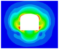
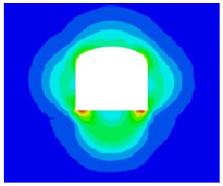
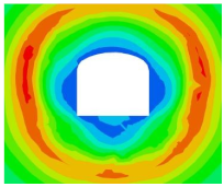
A partial cloud of unsupported and 15° angle bolt support is shown in the Table 8 below.

4.4.2. Length

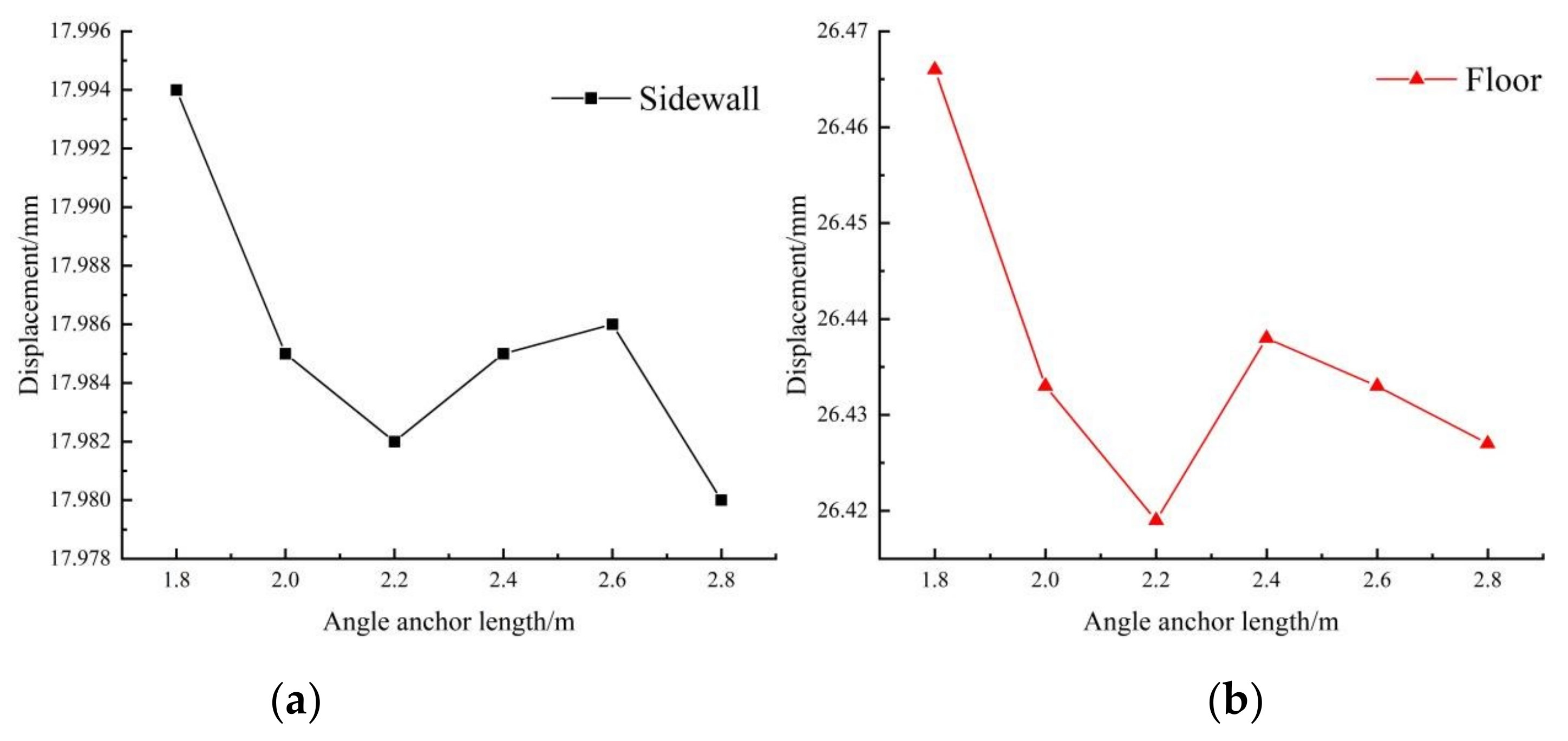
Combined with the above analysis, the 15° base-angle bolt inclined angle scheme is selected to study the influence of individually changing the base-angle bolt length on the overall supporting effect, and the new practice method of the theory of strong joint and strong angle is discussed. As shown in Figure 12, when the bolt length of the base-angle bolt is consistent with the bolt length of other parts, the displacement control effect of the base-angle area is the best, and the displacement control effect of the upper part is the second-best. Increasing or decreasing the bolt length of the base-angle bolt within a certain range has a negative impact on the control effect of the upper part and the floor.

5. Conclusions

Aiming at solving problems such as the difficulty in the range of parameter values of base-angle bolt support at the base-angle in the design of roadway support scheme, the simulation scheme of 5 kinds of section shapes under different base-angle bolt support angles is designed, and the actual engineering simulation is carried out in the Sanshandao Gold Mine to explore the influence of the change of base-angle bolt length and angle on the stability of the roadway; the main conclusions are as follows:
(1) Under the same geotechnical parameters, the self-supporting capacity of a roadway with different section shapes is different. The optimal order of overall self-supporting capacity is as follows: tri-centric arch > horseshoe shaped arch > circular arch > straight wall circular arch > rectangle.
(2) There are differences in the optimal inclined angle of the base-angle bolt in roadways with different cross-sectional profile shapes, but the general trend of all roadways is as follows: with the increase in the inclined angle from 0° to 90°, the roadway stability shows a trend of first increasing and then decreasing. When the inclined angle of the base-angle bolt is 15° to 45°, most of the shaped roadways can achieve a good supporting effect.
(3) When the length of base-angle bolt is changed separately, even if the length is increased to a certain extent, the overall supporting effect of the supporting structure will decline. Therefore, it is not necessary to blindly increase the length of the base-angle bolt separately to avoid adverse changes in the surrounding rock bearing structure.

Author Contributions

Conceptualization, Q.W. and H.L.; methodology, Q.W.; software, D.L.; validation, Q.W., H.L., and B.D.; formal analysis, B.D.; investigation, L.C.; resources, H.L.; data curation, L.C.; writing—original draft preparation, L.C.; writing—review and editing, D.L.; visualization, B.D.; supervision, P.Q.; project administration, P.Q.; funding acquisition, H.L. All authors have read and agreed to the published version of the manuscript.

Funding

This paper was funded by the following: Key Project of Education Department of Hunan Province(22A0293), General Project of Education Department of Hunan Province(22C0235).

Institutional Review Board Statement

Not applicable.

Informed Consent Statement

Not applicable.

Data Availability Statement

Not applicable.

Conflicts of Interest

The authors declare no conflict of interest.

References

  1. Zhao, X.; Zhou, X.; Zhao, Y.; Yu, W. Research Status and Progress of Prevention and Control of Mining Disasters in Deep Metal Mines. J. Cent. South Univ. Sci. Technol. 2021, 52, 2522–2538. [Google Scholar]
  2. Bai, J.; Hou, C.-J. Control Principle of Surrounding Rocks in Deep Roadway and Its Application. J.-China Univ. Min. Technol.-Chin. Ed. 2006, 35, 145. [Google Scholar]
  3. Shan, R.L.; Kong, X.S.; Yan, F.Y.; Meng, C. Research on Sidewall and Corner Strengthened Support for Coal Roadway by Modeling Experiments. Chin. J. Rock Mech. Eng. 2015, 34, 2336–2345. [Google Scholar]
  4. Shan, R.L.; Peng, Y.; Kong, Y.; Xiao, Y.; Yuan, B.; Zheng, Y. Research Progress of Coal Roadway Support Technology at Home and Abroad. Chin. J. Rock Mech. Eng. 2019, 38, 2377–2403. [Google Scholar]
  5. Kong, X.S.; Shan, R.L.; Ju, T.D. Model Experiment of Deformation and Failure Mechanism of Coal Roadway Surrounding Rock and Its Engineering Application. J. Min. Saf. Eng. 2017, 34, 464–471. [Google Scholar]
  6. Zheng, Y.; Shan, R.; Huang, B.; Feng, J.; Peng, R. Similar model tests on strong sidewall and corner support of gob side entry retaining. J. Min. Saf. Eng. 2021, 38, 94–102. [Google Scholar]
  7. Yang, S.; He, M.; Liu, W.; Ma, X. Mechanics and Application Research on The Floor Anchor to Control The Floor Heave of Deep Soft Rock Roadway. Chin. J. Rock Mech. Eng. 2008, 27, 2913–2920. [Google Scholar]
  8. Yang, J.; Shi, H.; Qi, G. Research on mechanism for floor heave control in the roadway by base-angel-bolt and its type selection test. J. Min. Saf. Eng. 2016, 33, 643–648. [Google Scholar]
  9. Liang, B.; Sun, H.; Li, G.; Wu, P. Genesis Analysis and Support Technology of Gob-side Entrydriving Floor Heave in Nanyangpo Coal Mine. Chin. J. Undergr. Space Eng. 2021, 17, 601–607. [Google Scholar]
  10. Dai, B.; Luo, X.; Shan, Q.; Chen, Y.; Liu, Y. Analysis on Damage Characteristics and Energy Dissipation of Rock with a Single Hole under Cyclic Impact Loads. China Saf. Sci. J. 2020, 30, 69. [Google Scholar]
  11. Dai, B.; Chen, Y. A Novel Approach for Predicting the Height of the Water-Flow Fracture Zone in Undersea Safety Mining. Remote Sens. 2020, 12, 358. [Google Scholar] [CrossRef] [Green Version]
  12. Dai, B.; Zhao, G.; Konietzky, H.; Wasantha, P.L.P. Experimental Investigation on Damage Evolution Behaviour of a Granitic Rock under Loading and Unloading. J. Cent. South Univ. 2018, 25, 1213–1225. [Google Scholar] [CrossRef]
  13. Dai, B.; Chen, Y.; Zhao, G.; Liang, W.; Wu, H. A Numerical Study on the Crack Development Behavior of Rock-Like Material Containing Two Intersecting Flaws. Mathematics 2019, 7, 1223. [Google Scholar] [CrossRef] [Green Version]
  14. Krykovskyi, O.; Krykovska, V.; Skipochka, S. Interaction of Rock-Bolt Supports While Weak Rock Reinforcing by Means of Injection Rock Bolts. Min. Min. Depos 2021, 15, 8–14. [Google Scholar] [CrossRef]
  15. Dyczko, A.; Kamiński, P.; Jarosz, J.; Rak, Z.; Jasiulek, D.; Sinka, T. Monitoring of Roof Bolting as an Element of the Project of the Introduction of Roof Bolting in Polish Coal Mines—Case Study. Energies 2022, 15, 95. [Google Scholar] [CrossRef]
  16. Małkowski, P.; Niedbalski, Z.; Majcherczyk, T.; Bednarek, Ł. Underground Monitoring as the Best Way of Roadways Support Design Validation in a Long Time Period. Min. Miner. Depos. 2020, 14, 1–14. [Google Scholar] [CrossRef]
  17. Das, R.; Singh, T.N. Effect of Rock Bolt Support Mechanism on Tunnel Deformation in Jointed Rockmass: A Numerical Approach. Undergr. Space 2021, 6, 409–420. [Google Scholar] [CrossRef]
  18. Esterhuizen, G.S.; Gearhart, D.F.; Klemetti, T.; Dougherty, H.; van Dyke, M. Analysis of Gateroad Stability at Two Longwall Mines Based on Field Monitoring Results and Numerical Model Analysis. Int. J. Min. Sci. Technol. 2019, 29, 35–43. [Google Scholar] [CrossRef]
  19. Ning, L. Study on Anchorage Mechanical Mechanism and Application of Rock Bolt in Composite Rock Mass. Chin. Univ. Min. Technol. 2021. [Google Scholar] [CrossRef]
  20. Liu, H.Y.; Zuo, J.P.; Liu, D.J.; Li, C.Y.; Xu, F.; Lei, B. Optimization of Roadway Bolt Support Based on Orthogonal Matrix Analysis. J. Min. Saf. Eng. 2021, 38, 84–93. [Google Scholar]
  21. Tian, J. Optimization of Support Design for Transport Channel of 3209 Working Face. Shandong Coal Sci. Technol. 2021, 39, 15–16. [Google Scholar]
  22. Guo, P.; Shen, D. Optimization design and numerical simulation of supporting scheme for deep mine roadway. Min. Saf. Envi. Prot. 2021, 48, 87–91. [Google Scholar]
  23. Shen, B.; Yuan, C.; Gu, W.; Liu, Z.; Song, T.; Pan, H. Research on the stability control of surrounding rock in the roadway with dynamic pressure and high slope. Ind. Mine Auto. 2021, 47, 50–55. [Google Scholar]
  24. Zhu, S.; Ding, K. Optimization of support parameters of water rich roadway based on thickness of grouting reinforce-ment circle. Saf. Coal Min. 2021, 52, 193–199+206. [Google Scholar]
  25. Zhao, W.; Fu, H.; Song, Y.; Ma, H.; Li, X. Failure Mechanism and Support Optimization of Sur-rounding Rock in Fault Crossing Roadway. Min. Res. Develop. 2021, 41, 129–134. [Google Scholar]
  26. Gao, L.; Deng, G.; Zhang, M.; Zhao, Q.; Ding, Y.; Zhang, E. Roadlway Surrounding Rock Control in Soft Rock Based on Theory of Composite Bolt-Rock Bearing Structure. Min. Res. Develop. 2021, 41, 140–144. [Google Scholar]
  27. Chang, L. Study on Timing Characteristics and Stability Control of Roadway Influences by Mining in High Stress Area. Taiyuan Univ. Technol. 2021. [Google Scholar] [CrossRef]
  28. Zhang, B.; Su, X.; Duan, Z.; Chang, L.; Fuzhou, W. Study on stability control of surrounding rock of roadway affected by driving disturbance. Min. Saf. Envir. Prot. 2020, 47, 19–24+31. [Google Scholar]
  29. Li, F. Anchor prestress field distribution characteristics and support optimization of multi type composite roof. Chin. Min. Mag. 2020, 29, 97–103. [Google Scholar]
  30. Zhai, Y. An Update of the 3D Analytical Solution for the Design of Barricades Made of Waste Rocks. Int. J. Rock Mech. Min. Sci. 2022, 158, 105176. [Google Scholar] [CrossRef]
  31. Cai, M.; Kaiser, P.K.; Morioka, H.; Minami, M.; Maejima, T.; Tasaka, Y.; Kurose, H. FLAC/PFC Coupled Numerical Simulation of AE in Large-Scale Underground Excavations. Int. J. Rock Mech. Min. Sci. 2007, 44, 550–564. [Google Scholar] [CrossRef]
  32. Skrzypkowski, K.; Zagórski, K.; Zagórska, A.; Apel, D.B.; Wang, J.; Xu, H.; Guo, L. Choice of the Arch Yielding Support for the Preparatory Roadway Located near the Fault. Energies 2022, 15, 3774. [Google Scholar] [CrossRef]
  33. Ma, S.-H.; Wang, W.-J. Comparative Analysis of Supporting Effect on Split-Set Bolt and GFRP Anchor Based on FLAC3D. Met. Mine 2012, 41, 9. [Google Scholar]
  34. Griffiths, D.V. Failure Criteria Interpretation Based on Mohr-Coulomb Friction. J. Geotech. Eng. 1990, 116, 986–999. [Google Scholar] [CrossRef]
  35. Hoek, E. Estimating Mohr-Coulomb Friction and Cohesion Values from the Hoek-Brown Failure Criterion. Int. J. Rock Mech. Min. Sci. Geomech. 1990, 27, 227–229. [Google Scholar] [CrossRef]
  36. Labuz, J.F.; Zang, A. Mohr–Coulomb Failure Criterion. Rock Mech. Rock Eng. 2012, 45, 975–979. [Google Scholar] [CrossRef] [Green Version]
  37. Dai, Y.; Chen, W.; Liu, Q.; Yi, X. Optimization Study on Cross Section of Deep Mine Tunnel under High in Situ Stress. Ch. Nese J. Rock Mech. Eng. 2004, 23, 4960–4965. [Google Scholar]
  38. Lü, A. Selection Method of Section Configuration of Underground Chamber in High Strata Stress Zone. J. China Coal Soc. 1997, 22, 495–498. [Google Scholar]
  39. Hou, M.Z.; Li, M.; Gou, Y.; Feng, W. Numerical Simulation and Evaluation of the Fracturing and Tight Gas Production with a New Dimensionless Fracture Conductivity (FCD) Model. Acta Geotech. 2021, 16, 985–1000. [Google Scholar] [CrossRef]
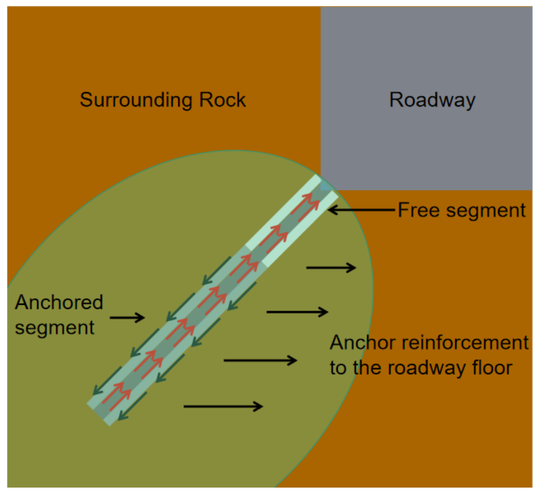
Figure 1. Schematic diagram of bolt reinforcement of the roadway floor by the base-angle bolt.
Sustainability 15 02496 g001
Figure 2. Five numerical models of a roadway.
Sustainability 15 02496 g002
Figure 3. Displacement and stresses in unsupported excavation of the roadway with different cross-sectional profile, among the rest: (a) Maximum displacement; (b) Maximum stress.
Sustainability 15 02496 g003
Figure 4. Effect of the angle of base-angle bolt support inclined angle on the displacement of 5 cross-sectional profiles of the roadway: (a) floor; (b) roof; (c) sidewall.
Sustainability 15 02496 g004
Figure 5. Effect of the angle of the base-angle bolt support inclined angle on maximum stress for 5 types of cross-sectional profiles of roadways: (a) vertical; (b) level.
Sustainability 15 02496 g005
Figure 6. Diagram of the roadway.
Sustainability 15 02496 g006
Figure 7. Initial stress field (Mohr–Coulomb).
Sustainability 15 02496 g007
Figure 8. Displacements of the three constitutive models: (a) elasticity; (b) Mohr–Coulomb; (c) Softening M–C; the units are all “m”.
Sustainability 15 02496 g008
Figure 9. Displacement at different gang angle support angles: (a) roof; (b) floor; (c) sidewall.
Sustainability 15 02496 g009
Figure 10. Maximum shear strain increment and maximum principal stress: (a) shear strain increments; (b) maximum principal stress.
Sustainability 15 02496 g010
Figure 11. Results of displacement and stress monitoring under the roadway floor: (a) displacement; (b) maximum principal stress; (c) maximum shear stress.
Sustainability 15 02496 g011
Figure 12. Roadway displacement of different lengths of base-angle bolts: (a) sidewall; (b) floor.
Sustainability 15 02496 g012
Table 1. Base-angle bolt parameters in the roadway support optimization literature (2020–2021) in China [21,22,23,24,25,26,27,28,29].
MinesCross-Sectional ProfileDepth of Burial/mInclined Angle of the Bolt at the Bottom of the Side Wall/°Yes or No
Base-Angle Bolt
Wangpo Coal Mine, 3209 working facesRectangular4505–15No
Songzao Coal and Electricity Company’s Datong I Mine,Straight wall, rounded arch50015No
15,312 working faces in a coal mineRectangular240–3000No
Taoyuan Coal Mine II Mining AreaStraight wall, rounded arch518–79930No
A coal mine pump room substation roadwayStraight wall, rounded arch85015No
21,126 Haulage Lane, Panjiang Hengpu Coal Industry, GuizhouStraight wall, rounded arch-10Yes
3316 working faces at Shuangliu Coal MineRectangular6000No
3# coal seam in a coal mineRectangular4530No
Longquan Coal Mine tape tunnelRectangular60015No
Yangquan Mine, Shang She Mine, Yangquan District, 9304 intake roadRectangular230–2700No
Table 2. Calculated constitutive model parameters.
Bulk Modulus K/GPaShear Modulus K/GPaCohesion C/MPaInternal
Friction Angle
ψ/(°)
Density γ/(t/m3)Tensile Strength
σt/MPa
1062302.61
The parameters are determined according to the common surrounding rock parameters of class II~III, which are not exact. The purpose is to study the universal law.
Table 3. Simulation scenarios for different inclined angles of the base-angle bolt.
TypeInclined
Angle/°
TypeInclined
Angle/°
TypeInclined
Angle/°
TypeInclined
Angle/°
TypeInclined
Angle/°
Rec0Hs0Tca 0Rou0Swsa0
Rec15Hs15Tca15Rou15Swsa15
Rec30Hs30Tca30Rou30Swsa30
Rec45Hs45Tca45Rou45Swsa45
Rec60Hs60Tca60Rou60Swsa60
Rec75Hs75Tca75Rou75Swsa75
Rec90Hs90Tca90Rou90Swsa90
Table 4. Cloud diagram of surrounding rock without support (plastic zone, displacement, vertical stress, horizontal stress, in turn).
RecHsTcaRouSwsa
Sustainability 15 02496 i001Sustainability 15 02496 i002Sustainability 15 02496 i003Sustainability 15 02496 i004Sustainability 15 02496 i005
Sustainability 15 02496 i006Sustainability 15 02496 i007Sustainability 15 02496 i008Sustainability 15 02496 i009Sustainability 15 02496 i010
Sustainability 15 02496 i011Sustainability 15 02496 i012Sustainability 15 02496 i013Sustainability 15 02496 i014Sustainability 15 02496 i015
Sustainability 15 02496 i016Sustainability 15 02496 i017Sustainability 15 02496 i018Sustainability 15 02496 i019Sustainability 15 02496 i020
Sustainability 15 02496 i021Sustainability 15 02496 i022Sustainability 15 02496 i023Sustainability 15 02496 i024Sustainability 15 02496 i025
Table 5. Surrounding rock parameters of the north lane of section 945 at the Xishan mine area, Sanshandao Gold Mine.
Bulk
Modulus K/GPa
Shear
Modulus K/GPa
Cohesion C/MPaPoisson’s Ratio
υ
Internal
Friction
Angle
ψ/°
Density γ/(t/m3)Tensile Strength
σt/MPa
21.089.734.00.3302.671.53
Table 6. Softening Mohr–Coulomb model of strain softening parameters.
Cumulative Shear Strain
Increment
00.010.11
Internal friction angle/°30272220
Cohesion/MPa420.50.1
Shear expansion angle/°10200
Table 7. Simulation design scheme.
ProgramNo.Inclined Angle of Base-Angle BoltLength of Base-
Angle Bolt
ProgramNo.Inclined Angle of Base-Angle BoltLength of Base-Angle Bolt
Unsupported1--Optimization of support (length)6151.8
7152.0
Optimization of support (angle)202.28152.2
3152.29152.4
4302.29152.6
5452.210152.8
Table 8. Comparison of unsupported and 15° base-angle bolt inclined angle support.
Unsupported15° Description
Sustainability 15 02496 i026Sustainability 15 02496 i027Sustainability 15 02496 i028Sustainability 15 02496 i029The maximum shear strain increase without support is mainly concentrated at the four gang corners of the roadway; after support, it is concentrated at the bottom gang corners, and the value increases by 0.68.
a. Maximum shear strain increment
Sustainability 15 02496 i030Sustainability 15 02496 i031Sustainability 15 02496 i032Sustainability 15 02496 i033Without support, the maximum shear stress is distributed in a circular pattern around the roadway; with support, the maximum shear stress area is closer to the roadway and is 1.21 MPa lower than without support.
b. Maximum shear stress(Pa)
Sustainability 15 02496 i034Sustainability 15 02496 i035Sustainability 15 02496 i036Sustainability 15 02496 i037The maximum principal stresses are located on both sidewalls of the roadway when there is no support; after the support, some of the maximum principal stresses are transferred to the upper and lower sidewalls and are 4.99 MPa lower than when there is no support.
c. Maximum principal stress(Pa)
Disclaimer/Publisher’s Note: The statements, opinions and data contained in all publications are solely those of the individual author(s) and contributor(s) and not of MDPI and/or the editor(s). MDPI and/or the editor(s) disclaim responsibility for any injury to people or property resulting from any ideas, methods, instructions or products referred to in the content.