Review

Recent Progress in the Cracking Mechanism and Control Measures of Tunnel Lining Cracking under the Freeze–Thaw Cycle

1
School of Highway, Chang’an University, Xi’an 710064, China
2
School of Science, Xi’an University of Architecture and Technology, Xi’an 710055, China
3
Sichuan Chuanjiao Cross Road & Bridge Co., Ltd., Deyang 618300, China
4
Shaoxing Communications Investment Group Co., Ltd., Shaoxing 312000, China
*
Author to whom correspondence should be addressed.
Sustainability 2023, 15(16), 12629; https://doi.org/10.3390/su151612629
Submission received: 21 April 2023 / Revised: 30 May 2023 / Accepted: 11 July 2023 / Published: 21 August 2023
(This article belongs to the Special Issue Advanced and Sustainable Technologies for Tunnel Engineering)

Abstract

:
With the rapid increase in the scale and number of tunnels in cold regions, the frost damage problems, such as cracking of the lining structure under the action of freeze–thaw cycles are becoming increasingly prominent. This review article collects and sorts out the frost damage phenomena that occur in the lining structure of tunnels in cold regions under the action of freezing and thawing cycles, classifies the frost damage phenomena into structural frost damage and non-structural frost damage, and proposes that the research on the mechanism of lining frost damage and its prevention measures should focus on lining cracking. According to the damage degree of the freeze–thaw cycle to the lining structure and its influence on tunnel operation, the cracking mode and cracking stage of lining are introduced. The analysis focuses on the mechanism of cracking in lining structures subjected to freeze–thaw cycles, considering the external force caused by frost heaving, the alteration of mechanical properties in lining concrete, and the internal changes in the microstructure of the concrete. Additionally, the factors that contribute to the occurrence of lining cracking are summarized. Based on this, corresponding control measures have been organized to provide reference for the development of cracking of the lining structure under the action of freeze–thaw cycle.

1. Introduction

With the rapid development of the economy, the number and scale of tunnels built have increased dramatically. Due to the wide distribution of cold regions, it is inevitable to build tunnels in cold regions, so the impact of the freeze–thaw cycle on tunnels cannot be ignored [1,2]. After a statistical investigation, Gao Yan found that among 122 tunnels built in high latitude seasonal freezing areas in Northeast China, 51 tunnels suffered from freezing damage after a freezing and thawing cycle, accounting for 41.8% [3]. The main forms of frost damage include lining cracking, side wall leakage and ice hanging, pavement ponding and ice, and lining falling off. Below, Figure 1 shows the freezing damage that occurred in tunnels in different cold regions of China. Icing blockages in Tien Shan No. 2 Tunnel occurred after it was put into operation, water seepage from open-side walls occurred in Wufeng Mountain Tunnel, lining cracking occurred in Leong Ka Peng No. 2 Tunnel, and water and ice on the roads occurred in Chiongba Tunnel. If lining cracking caused by freeze–thaw cycles is not treated in a timely manner, the structural integrity of the tunnel can be compromised, leading to a reduced load-bearing capacity and potentially posing a safety hazard. Cracks can also allow water infiltration, which can further deteriorate the lining and surrounding materials [4]. When the side walls of a tunnel in cold regions experience leakage and ice hanging due to frost damage, water infiltration through the side walls can lead to the weakening of the surrounding rock, potentially resulting in instability and collapse. Ice hanging from the side walls poses a direct safety risk to vehicles and pedestrians passing through the tunnel [5]. Water and ice on the road, which can cause hydroplaning and reduce friction, lead to hazardous driving conditions. If the lining of a tunnel in a cold region begins to fall off due to frost damage, the stability of the tunnel structure can be compromised, increasing the risk of collapse and endangering the safety of individuals using the tunnel [6]. Falling debris from the lining can also pose a direct hazard to vehicles and pedestrians passing through the tunnel. Additionally, the removal and replacement of damaged lining materials require substantial time and resources, leading to significant disruptions to tunnel operations and increased costs. Among them, lining cracking is the main form of tunnel freezing damage and causes more harm [7,8].
Cracking of the lining will cause instability of the lining structure, reduced safety and reliability, smaller tunnel headroom, tunnel leakage, and if the cracking expands further, it will produce lining off blocks or even sudden collapse, seriously threatening the safety of pedestrians and vehicles [9,10]. In addition, the tunnel needs to be constantly maintained and repaired due to lining cracking, which not only affects the normal operation of the tunnel, but also requires labor and material resources for maintenance, which is obviously contrary to the original purpose of tunnel construction. Therefore, the cracks of tunnel lining structure under freezing–thawing cycles began to attract people’s attention [11,12,13].
In this study, a comprehensive analysis is presented on the various forms of frost damage in lining structures subjected to freeze–thaw cycles. The focus of the research is primarily placed on the occurrence of lining cracking, as it is deemed to be the main area of investigation concerning frost damage in linings. The paper further summarizes the modes of cracking and the subsequent failure processes observed in linings under the influence of freeze–thaw cycles. Additionally, an exploration into the cracking mechanism and the factors that influence the behavior of lining structures in response to freeze–thaw cycles is conducted. Finally, a compilation of appropriate control measures is provided based on the findings. Overall, the objective of this article is to review and analyze the frost damage phenomena that occur in the lining structures of tunnels in cold regions under the influence of freeze–thaw cycles. The article also aims to enhance the understanding of the frost damage phenomena in tunnel linings and provide insights into the mechanisms of lining cracking as well as potential prevention measures to mitigate the detrimental effects of freeze–thaw cycles in cold regions.

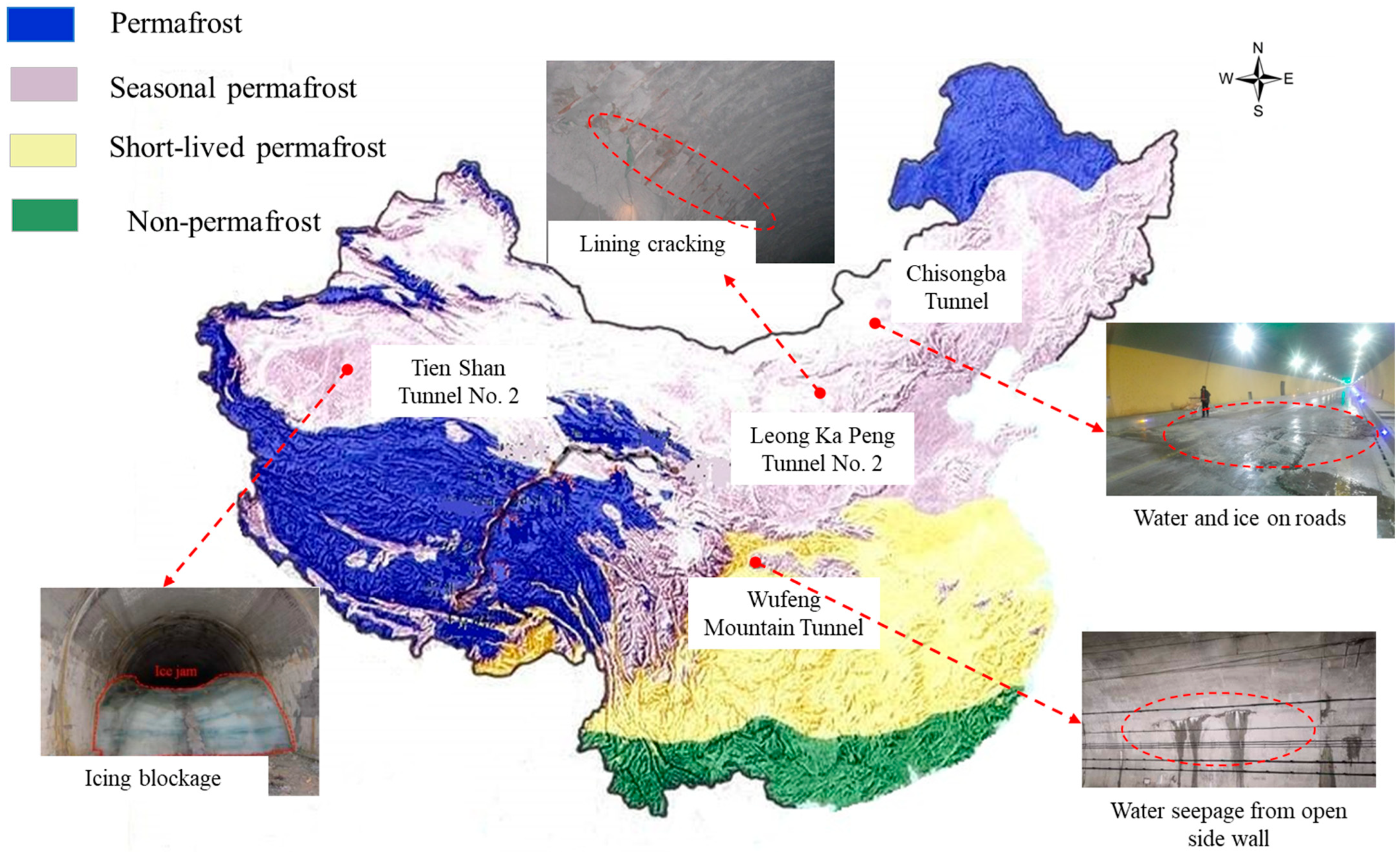
2. Investigation and Analysis of Freezing Damage of Lining Structure under Freeze–Thaw Cycle

The freeze–thaw cycle exerts detrimental effects on lining structures, leading to varying degrees of damage and posing a risk to traffic safety. In an effort to identify the common characteristics of freezing damage in lining structures subjected to freeze–thaw cycles, this section examines instances of tunnel lining damage resulting from freeze–thaw cycles in several cold regions. From the statistics, there are mainly three kinds of freezing damage occurring in the tunnel lining, namely lining cracking, lining leakage and icing, and lining shedding [14,15,16,17,18,19,20,21,22,23,24,25].
From the perspective of safe operation and durability and stability of tunnels, the three kinds of freezing damage are divided into two categories, namely structural freezing damage and non-structural freezing damage.
As shown in Figure 2 below. Lining leakage and icing belong to non-structural frost damage, while lining cracking and lining shedding belong to structural frost damage, of which lining cracks are mainly divided into four types, namely longitudinal cracks, reticular cracks, diagonal cracks, and transverse cracks [26,27]. Structural freezing damage will affect the stability of the lining structure, endanger the traffic safety in the tunnel, and have a greater risk of disasters. Non-structural freezing damage has little impact on the stability and safety of tunnel structure and traffic, and the risk of disaster is also small. However, it still needs attention and timely treatment. Otherwise, it will develop into more serious structural freezing damage [28,29].
Table 1 presents a summary of the frequency and percentage of occurrence for the three types of frost damage observed in the 20 tunnels located in cold regions. A total of 43 freezing damages occurred in 20 tunnels, and lining cracks occurred 19 times in 20 tunnels, accounting for 44% of the total. It is the main form of freezing damage to the lining structure. Leakage icing is also one of the common issues under freeze–thaw cycles in lining structures. It occurred 15 times, accounting for 35% of the total. Although the percentage of leakage icing is also high, lining cracking provides a channel for leakage, and icing occurs at low temperatures. Therefore, lining cracking is an important cause of leakage icing [30]. Lining shedding occurred only nine times, accounting for 21% of the total. Lining cracking is also a cause of lining shedding. If the cracks are not treated in time and allowed to develop further, lining shedding will occur after crack penetration. In addition, there are many types of lining cracking (see Figure 2). Transverse cracks are fractures that run perpendicular to the tunnel alignment. Longitudinal cracks are fractures that extend parallel to the tunnel line. Oblique cracks refer to fractures that exhibit an inclined direction relative to the tunnel axis. Reticulated cracks denote intricate networks of interconnected fractures within the lining structure. The presence of these cracks can weaken the lining structure, leading to reduced load-bearing capacity, increased water permeability, and potential safety hazards [31]. Understanding the different types of cracks and their causes is essential to assess the severity and potential consequences of tunnel lining frost damage. By identifying these cracks, appropriate preventive measures and maintenance strategies can be implemented to mitigate their impact on the tunnel operation. Therefore, research on the mechanism and prevention measures of lining damage under freeze–thaw cycles should focus on lining cracks.

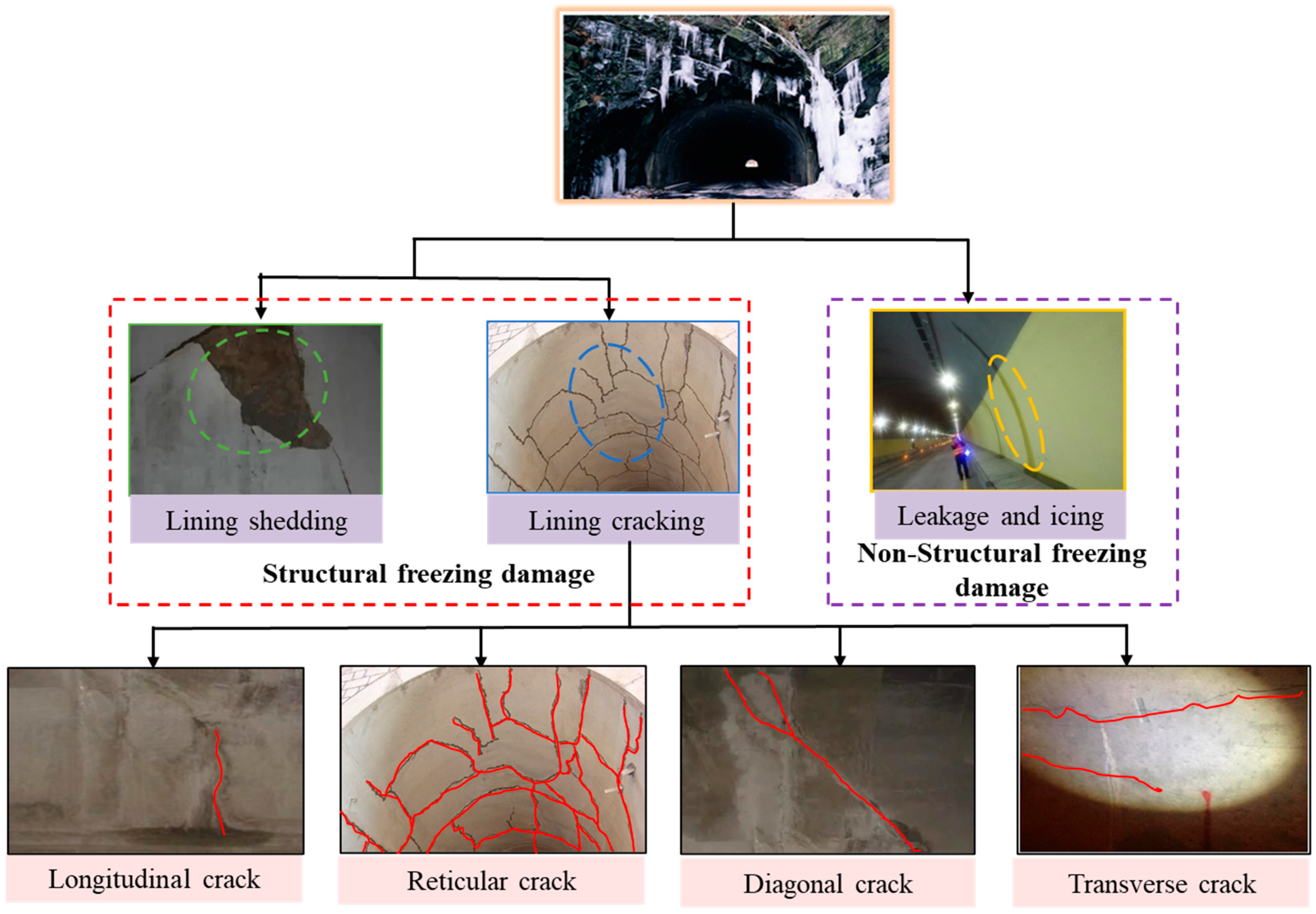
3. Cracking Failure Characteristics of Lining under Freeze–Thaw Cycle

3.1. Cracking Failure Mode of Lining Structure under Freeze–Thaw Cycle

As the freeze–thaw cycle introduces frost heaving forces to the lining structure, it results in damage of varying degrees. It is important to note that the position and magnitude of the frost heaving forces typically differ, further contributing to the variability in lining damage. According to the position and shape of the damage to the lining structure, the lining cracking can be divided into tension cracking and shear cracking [32,33]. Table 2 below shows the causes, features, and illustration of the two crack modes.
The impact of frost expansion force on the lining structure is complex. The force can induce stress concentrations in the lining, leading to the development and propagation of cracks. This will weaken the structural integrity of the lining and compromise its ability to withstand external loads and impact the overall stability of the tunnel. Additionally, the freeze–thaw cycles will increase permeability to water and other substances and cause potential structural damage. Therefore, freezing forces pose significant challenges to the durability and functionality of the tunnel lining structure [36]. Composite cracks composed of two modes often appear in the lining structure. According to the stress state of the crack surface, composite cracks can be divided into tension shear cracks and compression shear cracks. Tension shear cracks are mainly affected by tensile stress and shear stress while compression shear cracks are mainly affected by compressive stress and shear stress [37].

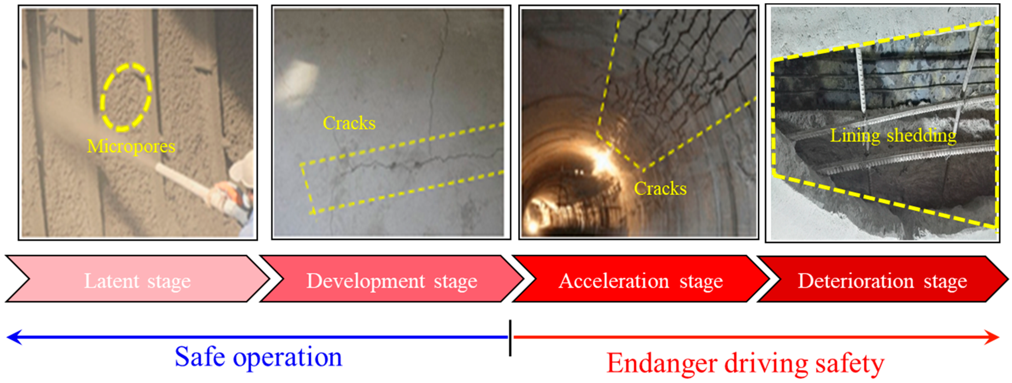
3.2. Cracking and Failure Stage of Lining Structure under Freeze–Thaw Cycles

During the freeze–thaw cycle, the performance of lining concrete gradually deteriorates with an increasing number of freeze–thaw cycles. According to the change in damage degree and properties of lining concrete, the deterioration process can be divided into four stages: latent stage, development stage, acceleration stage, and deterioration stage. The extent of damage to the lining structure at each stage and its impact on the tunnel operation are shown in Figure 3 below. In the latent and developmental stages, the cracking has less impact on the bearing capacity and integrity of the lining structure and has not yet affected the normal operation of the tunnel, which can still be operated safely. In the acceleration stage and the deterioration stage, the lining structure has obvious cracking, even shedding and falling blocks. At this point, the integrity of the lining structure is damaged, the lining structure’s load-bearing capacity is significantly reduced, which has threatened the safe operation of the tunnel [38,39,40,41].
In the latent stage, during the construction of the lining, due to the fact that construction reasons lead to the lining, the concrete is not dense, and there will be small pores between the cement slurry and the aggregate due to the hydration of the lining concrete material during the forming and hardening of the lining concrete. This kind of concrete is not dense and micropores become the inducing factor of lining structure cracking. As the number of freeze–thaw cycles experienced by the lining structure increases, the micropores continue to expand and connect, forming voids with larger pore sizes.
In the development stage, the freeze–thaw cycling action caused stress concentrations in the lining structure around the existing micropores and microcracks. These stress concentrations promote further crack development and expansion. Visible cracks begin to appear on the surface of the lining structure, and signs of water leakage, icing, and other freeze-related damage become apparent. At this stage, the surrounding rock properties affect the severity of stress concentrations and crack development, and if the surrounding rock properties are poor and generate additional loose deformation pressures the lining structure will be more susceptible to cracking and leaking.
In the acceleration stage, with the increase of tunnel service time, the number of freeze–thaw cycles experienced by the lining structure also gradually increases, and the cracks on the surface of the lining structure gradually show multi-directional growth. At the same time, the mechanical parameters and working performance of the lining concrete also accelerate deterioration. The lithology of the surrounding rocks play a crucial role in amplifying the effects of freeze–thaw cycles and exacerbating the deterioration of the lining structure.
During the deterioration stage, the accelerated expansion of cracks had a serious negative impact on the working performance of the lining structure. The expansion of cracks led to serious damage to the integrity of the lining structure, resulting in a significant reduction in the bearing capacity of the lining structure, the appearance of exposed aggregates and reinforcement on the lining surface, and a gradual increase in the degree of damage, which could no longer share and transfer the load effectively. This eventually led to the collapse and complete damage of the lining structure.
The relationship between these different phases of lining structure cracking is progressive and interconnected. The latent stage sets the foundation for subsequent crack development, with the presence of micro-gaps acting as initial points of weakness. The development stage sees the amplification and expansion of cracks, leading to visible damage and freezing-related problems. The acceleration stage accelerates the deterioration of the lining structure, resulting in multi-directional crack growth and the degradation of mechanical properties. Finally, the deterioration stage signifies the advanced stage of failure, with a significant reduction in bearing capacity and potential structural damage. Throughout these phases, the lithology of the surrounding rocks interacts with the freeze–thaw cycles, impacting the severity and progression of cracking in the lining structure.

4. Analysis of Cracking Failure Mechanism of Lining Structure under the Action of Freeze–Thaw Cycle

4.1. Frost Heaving Force behind Lining

Frost heaving force is a kind of deformation pressure produced under the common limitation of surrounding rock and lining when the water in surrounding rock fissure freezes and expands [42]. When the frost heave force acts on the lining structure, additional stress will be generated inside the structure, which will resulting in cracks, falling off, and other frost damage to the lining structure.
Researchers have done a lot of research on how the frost heaving force acts on the lining structure and its calculation methods, and put forward a variety of theoretical models, which are mainly divided into three types: the frost heaving model of water bearing weathering layer, localized water frozen swell model, and integral freeze–thaw circle model [43].

4.1.1. Water-Bearing Weathering Layer Model

After a large number of investigations, Japanese researchers found that a 10–20 cm thick fractionated layer existed from the arch shoulder to the sidewall in tunnels where frost damage occurred and that the water in the fractionated layer was subject to frost swelling in winter. The Chinese researcher Zhang Zhidao derived the equation for calculating the load during frost swelling of water-bearing differentiated layers on the basis of which he proposed a water-bearing weathering layer model. Its calculation model assumes that the water-bearing weathering layer surrounding rocks on both sides of the tunnel undergoes frost heave, that there is almost no frost heave on the vault, that the frost heave force can be replaced by lateral pressure, and that the lateral frost heave force (q) is derived based on the elastic resistance coefficient [44].
q = α δ k 1 k 2 / k 1 + k 2
where δ is the thickness of frost heave layer, α is the frost heave rate, k 1 is the circumferential deformation stiffness of the tunnel lining, and k 2 is the elastic resistance of the rock mass out of the weathering layer.

4.1.2. Localized Water Frozen Swell Model

The initial proposal of a localized water frozen swell model was made by Wang Jianyu. The localized water frozen swell model considers that the frost swell force is mainly caused by the frost swell of water accumulated in the unconfined space existing behind the lining. In order to simplify the calculation, the waterlogged space behind the lining is considered as a triangle, and the calculation formula for the frost swelling force is derived based on the volume of the water after freezing and expansion and the volume of the waterlogged space after deformation under the action of the frost swelling force being equal [45].
σ f = α V / n i = 1 s i k i + s L k L
where α is the volume expansion rate when water freezes into ice; V is the volume of frost heaving water body; s i and s L are the areas of the ith constraint surface of lining and surrounding rock, respectively; k i is the compressive stiffness of the ith compression surface of surrounding rock; and k L is the lining stiffness.

4.1.3. Integral Freeze–Thaw Circle Model

Lai Yuanming et al. assumed that the freeze–thaw cycle is freeze-distended in all directions during the freeze-distension period, thus deriving a viscous solution for the freeze-distension force. Based on this, an integral freeze–thaw cycle model was proposed [46].
σ f = n α E 2 / p q + ( m 2 + 1 ) ( e m 1 μ 1 + m 2 + μ 2
where n is the porosity of surrounding rock; α is the expansion coefficient of water to ice; E 1 , E 2 , μ 1 , and μ 2 are the elastic modulus and poisson’s ratio of lining and surrounding rock, respectively; and a, b is the inner diameter and outer diameter of the lining concrete lining: p = 2 b 2 / { b + H f 2 b 2 } ; q = 2 b + H f 2 / { b + H f 2 b 2 } ; e = E 2 / E 1 ; m 1 = ( a 2 + b 2 ) / ( a 2 b 2 ) ; m 2 = { b + H f 2 + b 2 } / { b + H f 2 b 2 } .
The calculation formula, advantages, disadvantages, and applicability of each model are shown in Table 3 below.

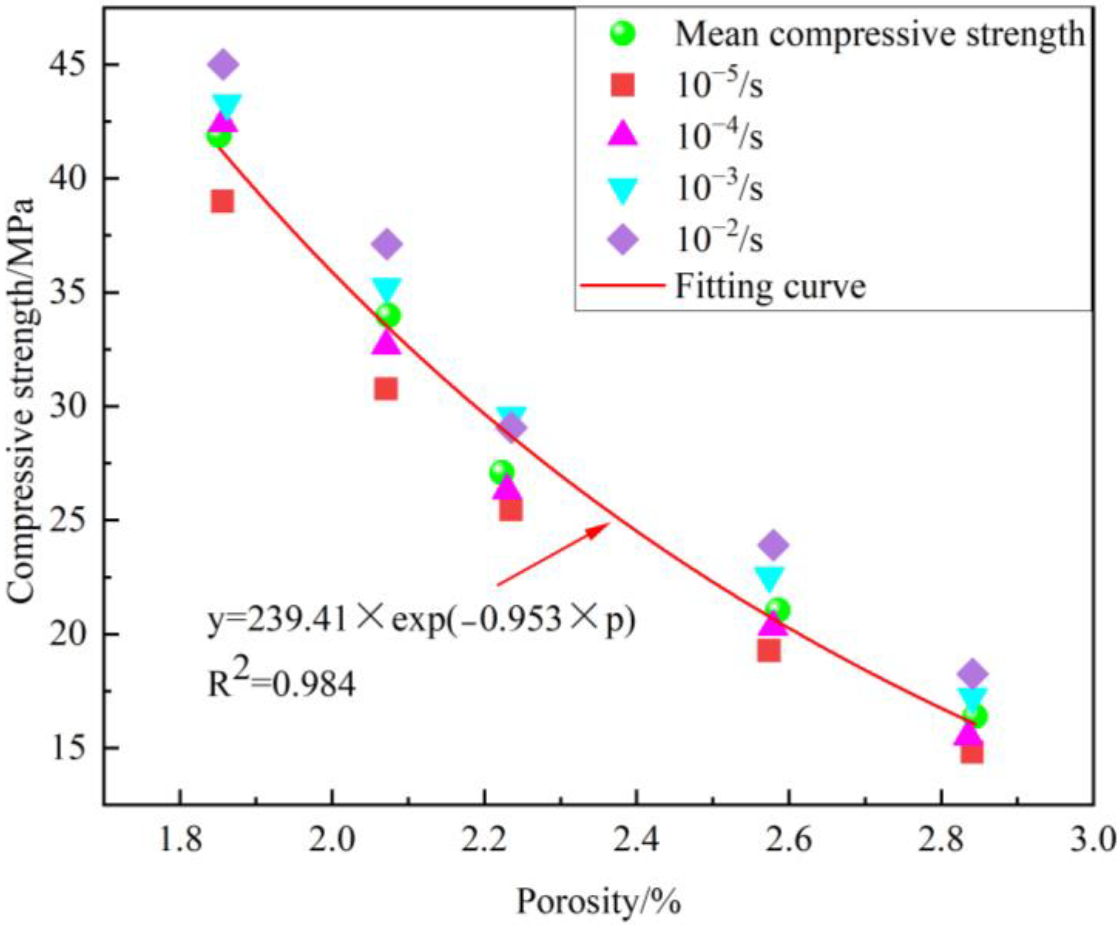
4.2. Changes in Mechanical Properties of Lining Concrete under Freeze–Thaw Cycles

The lining concrete will crack and drop slag after several freeze–thaw cycles, which will cause quality loss. Therefore, the damage degree of the lining concrete sample during the freeze–thaw cycle can be directly expressed by the mass loss rate of the sample. And the relative dynamic elastic modulus is usually used to evaluate the deterioration degree of the internal structure of the lining concrete sample during the freeze–thaw cycle. The Figure 4 below shows the change in mass loss rate and relative dynamic elastic modulus of lining concrete specimens under freeze–thaw cycles [48].
Figure 4 illustrates that the mass loss rate initially exhibits a negative trend during the early stages of the freeze–thaw cycle. This can be attributed to the damage inflicted upon the internal pores of the lining concrete as a result of the freeze–thaw cycle, subsequently leading to an increase in water content within the sample post-freeze–thaw [49]. Then, with the increasing number of freeze–thaw cycles, the mass loss rate increases continuously due to cracking and falling off until the sample is damaged. Furthermore, it is evident that as the number of freeze–thaw cycles increases, the relative dynamic elastic modulus of the lining concrete gradually decreases. Notably, after the 100th freeze–thaw cycle, the decline in the relative dynamic elastic modulus of the lining concrete specimens becomes more pronounced and rapid. The reason behind this phenomenon is the occurrence of early-stage damage in the lining concrete specimens during the freeze–thaw cycle. This damage primarily manifests as tiny cracks in the transition zone between the aggregate and mortar components of the concrete. With the increase in freeze–thaw cycle times, cracks gradually expand and finally form a large number of cracks, resulting in the loss of cement and slurry. The compactness of lining concrete decreases rapidly, so the decline rate of the relative dynamic elastic modulus of lining concrete gradually accelerates.
The results of the mass loss test and dynamic elastic modulus test show that the mechanical properties of lining concrete will deteriorate significantly after many freeze–thaw cycles, especially after 100 freeze–thaw cycles, its mechanical properties decline more obviously. This further explains that the lining structure has less cracking at the initial stage. With the increase of service time, the cracking degree and number of lining concrete gradually increase, and the cracking speed is faster.

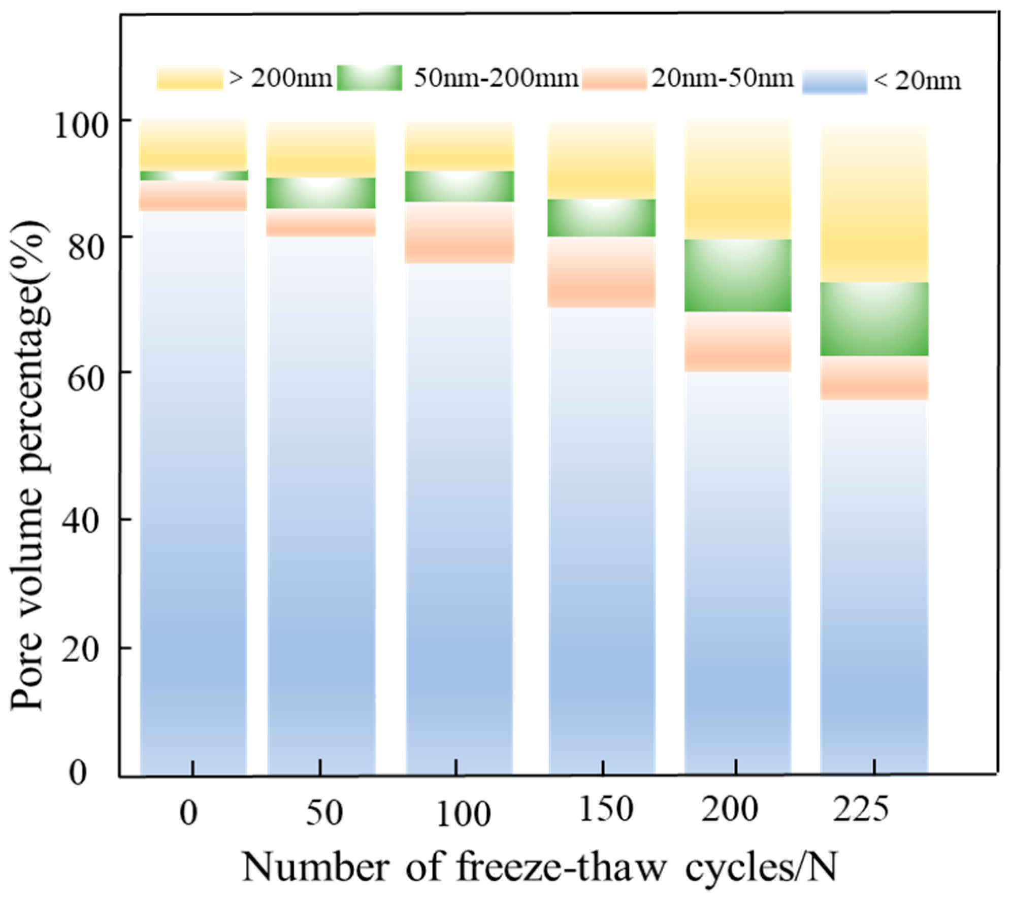
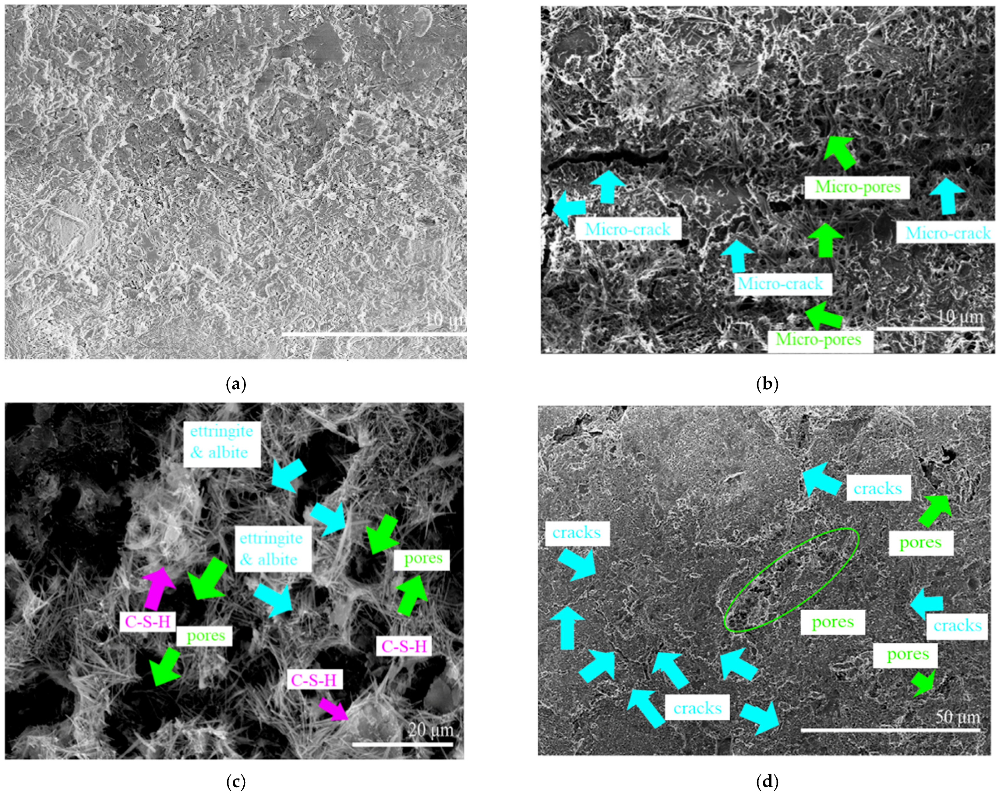
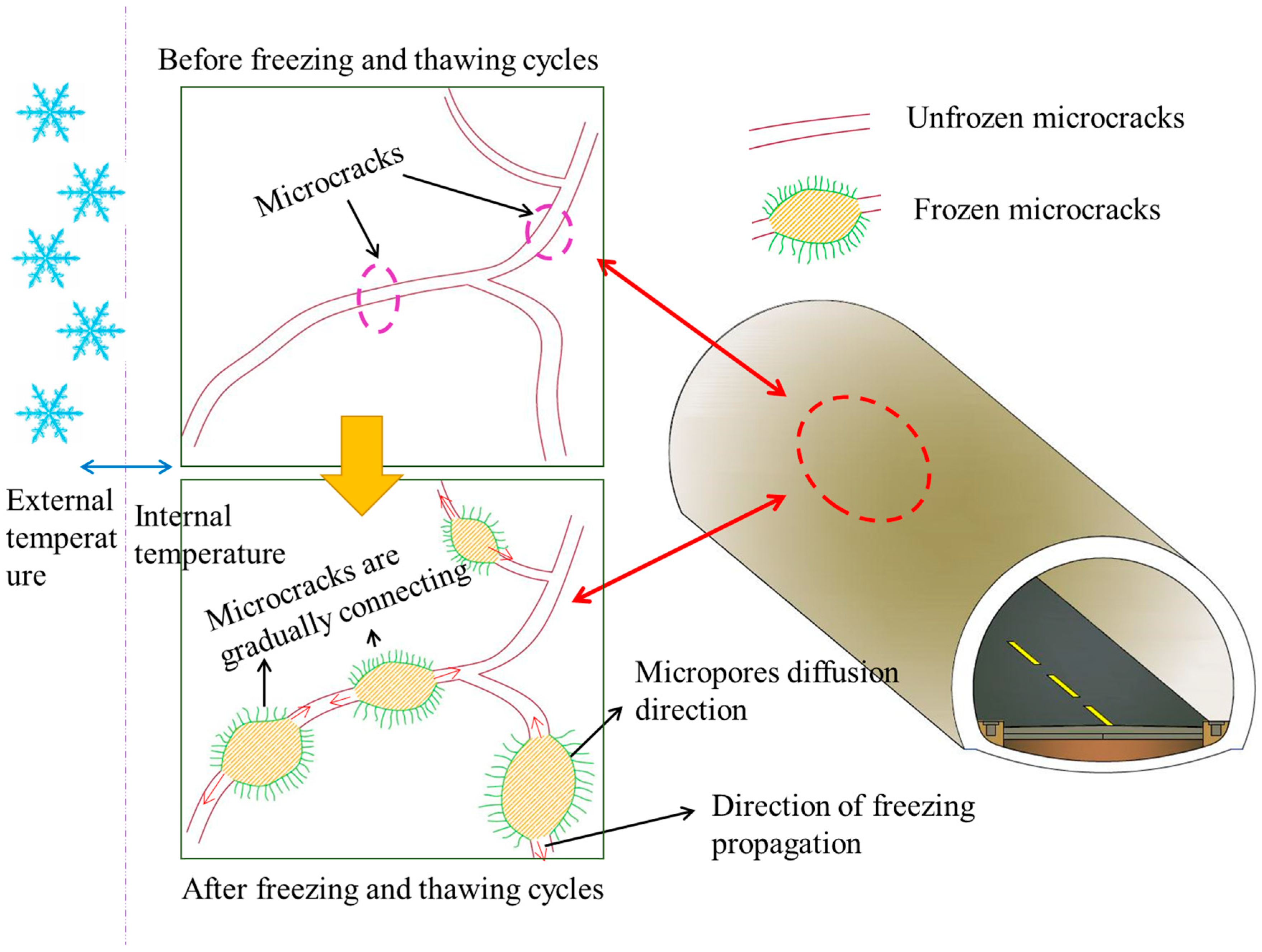
4.3. Pore and Microstructure Change of Lining Concrete under Freeze–Thaw Cycle

The internal pore structure of lining concrete is closely related to frost resistance and cracking resistance. The internal pores provide water storage space, and cracks will be formed if the pore structure further develops. Therefore, the influence of the internal pore structure of lining concrete under the action of freeze–thaw cycle cannot be ignored.
The following Figure 5 shows the change of the pore volume percentages of lining concrete after freeze–thaw cycle [50]. The observation from Figure 5 reveals that prior to the freezing and thawing process, the proportion of benign pores (with a pore size less than 20 nm [51]) is significantly higher compared to the other three categories of pores. With the increase of freeze–thaw cycles, the pore structure continues to deteriorate, small pores continue to develop, expand, and form medium and large pores. The proportion of harmful pores (pore size greater than 50 nm and less than 200 nm [51]) and multi harmful pores (pore size greater than 200 nm [51]) gradually increases, and pores and microcracks in lining concrete continue to expand. The freeze–thaw cycle causes a large number of harmful pores and multiple harmful pores in the lining concrete, which greatly destroys the durability of the lining structure. This factor also contributes significantly to the gradual decrease in both the mass loss rate and the relative dynamic elastic modulus of the lining concrete. Figure 6 presents the correlation between NMR porosity and compressive strength, indicating that the compressive strength diminishes exponentially with an increase in porosity. This observation further underscores the influence of changes in concrete microporosity on its workability [50].
The microstructural changes in the lining concrete can further explain the cracking mechanism under the action of freeze–thaw cycles. Figure 7 below shows the changes in the microstructure of lining concrete under SEM after freeze–thaw cycles of different times. From Figure 7, it can be seen that the unfreeze–thawed lining concrete is uniformly dense inside with a large number of submicron or nano-scale pores between the hydration products, which provides a good basis for the frost resistance of the lining concrete. The microstructure of the lining concrete is uniform and dense without cracks. After 100 freeze–thaw cycles, the micropores in the lining concrete gel increase in size under the freeze–thaw stress, forming microcracks at the top and extending along the weak surface, and finally penetrating to form cracks. The gel of the lining concrete had been dispersed, and only the network structure of interwoven ettringite and dolomite crystals remained. A large number of pores with diameters over 20 um appeared, and the number of microcracks increased rapidly and interconnected to form the main cracks. When the number of freeze–thaw cycles reached about 200, the microcracks grew rapidly and interconnected to form more pronounced cracks. These cracks eventually lead to the formation of significant cracking and loosening [51].
The fundamental reason for this process is that, as the number of freeze–thaw cycles increases, the capillary walls within the concrete are subjected to increasing expansion stresses. At the same time, the cementitious capacity of the hardened cement paste gradually decreases. The combined effect of the increased swelling stress and the reduced cementing capacity leads to the gradual deterioration of the lining concrete. The width of the cracks increases over time, eventually leading to damage to the lining concrete [52,53].

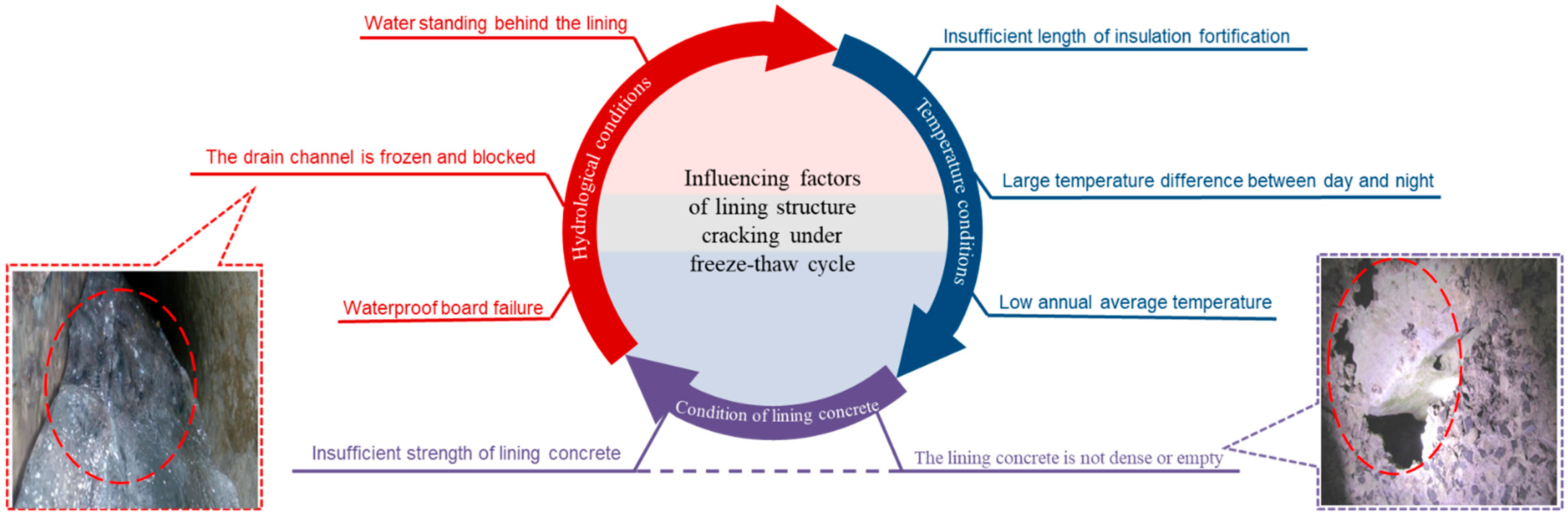
4.4. Analysis on Influencing Factors of Lining Structure Cracking under Freeze–Thaw Cycle

To explore the main factors affecting the cracking of the lining structure under the action of the freeze–thaw cycle, the causes of freezing damage in Table 1 are counted. As can be seen from Figure 8 below, there are many direct causes for cracking of the lining structures, such as water standing behind the lining, low annual average temperature, and un-dense structure etc. but they can be summarized into three categories: temperature conditions, hydrological conditions, and self-condition of the lining concrete.
(1)
Temperature conditions
Temperature is a key factor in freezing damage to tunnel lining structures. During the freeze–thaw cycle, the temperature fluctuations cause thermal stress within the lining [54]. The heat exchange between the cold external environment and the heat stored in the lining structure results in a net heat loss. As a result, the lining structure experiences negative temperatures. Under negative temperature conditions, water present within the lining structure undergoes freezing and expansion [55]. As water freezes, it expands, exerting pressure on the surrounding materials. The repeated freezing and thawing cycles lead to continuous expansion and contraction, generating significant stress on the lining structure. This stress can ultimately result in the development of cracks in the lining.
(2)
Hydrological conditions
Water is critical to the formation of frost heave in tunnel lining structures. Frost heave occurs when there is an adequate supply of water in the lining. Water can infiltrate into the lining structure through various sources such as groundwater, surface water or condensate. There are three different forms of pore water present within liner concrete, including chemically bound water, physically adsorbed water, and free water. The freeze–thaw cycle effect on chemically bound water basically has no effect. The physically adsorbed water is particularly small, and the general freezing point is below −78 °C, so the effect on the conventional freeze–thaw cycle effect is also small [56]. The third part is free water, in the freeze–thaw cycle process, the free water in the concrete pores of the concrete caused the most serious freeze–thaw damage. In the freeze–thaw cycle, the freezing of free water within the lining concrete structure will not only lead to an increase in volume and expansion, but also generate mechanical stress. As the free water freezes and expands, it exerts pressure on the surrounding materials, including the lining concrete. The resulting expansion forces can induce cracking and damage the integrity of the lining structure [57]. Based on the test results, a conceptual model of free water migration in pores of different sizes during freezing induces deterioration of the lining concrete as shown in Figure 9 below [50]. In addition, as free water moves, it carries dissolved salts and other impurities that can accumulate in specific areas. These accumulated salts can further lead to the deterioration of the lining structure, promoting additional cracking and weakening its overall performance.
(3)
Self-condition of lining concrete
The characteristics and quality of the lining concrete itself play a crucial role in frost damage susceptibility. Insufficient vibration or inadequate compaction during the pouring and placement of the lining concrete can result in the formation of various-sized pores within the concrete matrix. These pores provide spaces for excess water storage within the lining concrete. When freezing occurs, the trapped water within the pores freezes and expands, generating internal stresses. The expansion of freezing water within the concrete can lead to the development of internal microcracks and macrocracks, compromising the structural integrity of the lining. Additionally, the presence of these pores and voids can increase the permeability of the concrete, allowing more water to infiltrate the lining structure. This further exacerbates the frost damage by providing more water for frost heaving and increasing the potential for cracking [58].
Freezing–thawing cracking of lining concrete is the result of water, air temperature, and lining concrete’s own conditions, as shown in the Figure 10 below. During the freezing–thawing cycle, the temperature always changes alternately, which causes the excess water in the pores to freeze, expand, and recover repeatedly, which leads to the further expansion of the pores or cracks in the lining and finally causes the cracking of the lining structure [38].

5. Control Measures for Lining Cracking under Freeze–Thaw Cycle

Based on the analysis of the cracking failure mechanism of the lining structure under the aforementioned freeze–thaw cycle, in order to mitigate the occurrence of cracking and enhance the stability and safety of the lining structure during the construction and operational phases, three key aspects should be considered: temperature control, water management, and the self-condition of the lining concrete.

5.1. Change the Temperature Conditions around the Lining Structure

Negative temperature is a necessary condition for water to frost heave. If the lining and surrounding rock are always in a positive temperature state, the freeze–thaw cracking of the lining structure can be effectively prevented. At present, the main measures include passive thermal insulation and active thermal insulation [59]. Passive thermal insulation refers to the effect of thermal insulation by delaying the temperature reduction and freezing trend in lining and surrounding rock. Active thermal insulation is to artificially and appropriately supply heat to the surrounding rock of the tunnel to slow down or eliminate the tendency of freezing to achieve the purpose of thermal insulation. Active and passive thermal insulation measures are shown in Table 4.
It is worth noting that the geothermal energy used in ground source heat pump technology is a clean and environmentally friendly energy source, the current utilization of which is not high, and there is still a lot of potential and space for development [65]. Ground source heat pump technology can not only realize the tunnel’s anti-freeze insulation, but also meet the green, environmentally friendly concept of sustainable development. Therefore, although ground source heat pump technology has not yet been applied to engineering on a large scale, it has great potential for development.

5.2. Change the Hydrologic Conditions around the Lining Structure

If the hydrological conditions around the lining structure can be effectively changed, the cracking of the lining structure caused by the freeze–thaw cycle can be reduced or eliminated. According to the different principles of changing the hydrological conditions of tunnels, they can also be divided into two categories, namely active water plugging and passive drainage. Active water plugging involves the application of grouting and other techniques to seal cracks and water pathways in the surrounding rock, effectively preventing water seepage. On the other hand, passive drainage refers to the drainage of water that has infiltrated the tunnel area through measures such as insulated drainage ditches, allowing it to be safely discharged from the tunnel area.
Active water plugging is commonly used for smearing, grouting, and the use of special waterproofing materials. For the lining, smaller cracking caused by the tunnel vault, and side walls of the linear drip or surface deep water, part of the water stopping materials can be used to stop water. When the amount of seepage occurring on the inner surface of the tunnel is small, if the vertical and horizontal clearance of the tunnel cross-section is still rich, leaking water should first be addressed at the wall treatment clean; after, the special waterproofing materials can be directly sprayed with construction machinery or coated in the seepage [68]. When the amount of seepage occurring on the inner surface of the tunnel is large, such as water flowing outward in a condition visible to the naked eye or presenting jetting and other situations at the seepage, the most commonly used active water plugging measure is grouting, which fills the cracks with cement through grouting to plug the voids and seepage channels. Cement has the effect of heat of hydration, which can make itself freely diffuse in the gap, penetrate deeply into all parts of the gap, and then achieve the effect of sealing. In addition, grouting and water plugging can also fill the water storage space behind the lining, which is prone to induce frost pressure, such as cavities, fissures, and over-excavation of the surrounding rock. In the construction of the Gaoligongshan tunnel, the water output from a single hole was about 100 m2/h [69]. The construction crew used the method of mainly plugging and limiting the drainage, which effectively solved the problem of massive water seepage. It can also be used to first slot the seepage point and restore the lining surface with concrete after slotting; when the lining cracks are large or the lining cracks can no longer be repaired, when the lining has lost its bearing capacity, etc., the damaged lining can be replaced, and concrete materials with high quality grade and strength grade can be used.
A thermal insulation ditch is the most commonly used drainage measure in a cold tunnel. It is generally located on both sides of the road inside the tunnel. It has a shallow burial depth, convenient maintenance, and an obvious drainage effect, but it is only applicable to the area where the coldest month average temperature is between −5 °C and −15 °C. To overcome this limitation and make the application scope of thermal insulation ditch more extensive, Li Yao et al. have proposed the electric auxiliary heating system, and its working principle is shown in the Figure 11 below. When the temperature in the ditch is lower than 0 °C, the temperature sensor transmits a signal to the control box to enable the bottom heating plate. When the temperature is extremely low, the bottom heating plate cannot stop icing, and icing occurs in the ditch; then, the ice melting sensor transmits a signal to the control box, which enables the heating plates on both sides, realizes its ice melting function, and ensures the drainage of the ditch is smooth [70].

5.3. Change the Frost Resistance Condition of Lining Concrete

The state of lining concrete is also one of the important factors affecting the cracking of the lining structure under freezing–thawing cycles. If the frost resistance of lining concrete can be effectively improved, the cracking failure of the lining structure under the action of the freeze–thaw cycle can be eliminated or delayed. To improve the frost resistance of concrete, fiber and other additives are often used [71] (see Table 5).

6. Conclusions, Discussion, and Recommendations for Future Research

6.1. Conclusions

This paper investigates and analyzes the frost damage phenomenon of lining structures under the action of freeze–thaw cycles and classifies the frost damage phenomenon into two categories: structural frost damage and non-structural frost damage. Further analysis shows that both structural and non-structural frost damage are inseparable from lining cracking. Therefore, the research on the mechanism of lining disease under the action of freezing and thawing cycle and its prevention measures should focus on lining cracking. The cracking under freeze–thaw cycle is mainly tensile crack, shear crack and composite crack composed of two modes. According to the damage degree and performance change of lining concrete materials, the deterioration process is divided into four stages, namely latent stage, development stage, acceleration stage, and deterioration stage.
The frost heaving force due to the limited volume expansion of the surrounding rock fissure water under the freeze–thaw cycle is the main external cause leading to the cracking of the lining structure. Researchers have put forward three theoretical models on how the frost heaving force acts on the lining structure, namely the frost heaving model of the water bearing weathered layer, the local water accumulation frost heaving model, and the overall frost heaving model of the freeze–thaw circle. The mechanical properties and microstructure of the lining concrete gradually deteriorate with the increase of freeze–thaw cycles, the hardened cement paste gradually cracks, and the microcracks continue to form and expand, eventually leading to the formation of harmful cracks, looseness, and even damage of the lining concrete. The direct causes of lining structure cracking are analyzed, which are classified into three categories: temperature, hydrology, and lining concrete conditions, and the interaction among them is introduced.
Based on the factors affecting the cracking of the lining structure and the microscopic mechanism under the action of freeze–thaw cycles, the corresponding control measures are put forward, namely changing the temperature conditions, hydrological conditions, and the frost resistance of the concrete itself. According to the principle of changing temperature conditions, thermal insulation measures are divided into two categories: active thermal insulation and passive thermal insulation. According to the principle of changing the hydrological conditions of the tunnel, it can also be divided into two categories: active water blocking and passive drainage. The frost resistance condition of concrete itself can be changed by adding admixtures, and the properties of the three different additives are mainly introduced.
Overall, this paper demonstrates creativity in its approach to understanding frost damage in tunnel lining structures under freeze–thaw cycles. It creatively classifies the damage into structural and non-structural categories and emphasizes the importance of focusing on lining cracking. The article creatively analyzes frost damage from multiple perspectives, considering the degree of damage, cracking modes, stages of deterioration, and factors such as external frost heaving force, mechanical property changes, and microstructure alterations. It also proposes innovative control measures, including modifying temperature and hydrological conditions and enhancing the frost resistance of concrete with admixtures.

6.2. Discussion

The cracking failure modes of lining structures under the action of freeze–thaw cycles are described in Section 3.1, but they are only the two most basic failure modes, and the actual situation is often a combination of two failure modes superimposed. Therefore, when facing the actual working conditions, attention should be paid to the comprehensive consideration of the two failure modes.
With regard to the different stages of lining cracking under freeze–thaw cycles, in the initial and development stages, cracking does not affect the safe operation of the tunnel, but it should be noted that the cost of dealing with cracking in these two stages is much smaller compared to the latter two stages. Therefore, operation and maintenance personnel should pay more attention to the initial and developmental stages of lining cracking in order to avoid paying a higher price.
Although researchers have done a lot of research on these three calculation models, there is still a big gap compared with the actual project. The theoretical model needs further improvement, such as considering the uneven freezing and thawing of the surrounding rock, considering the water supply, etc.
Researchers have conducted many studies on measures to control lining cracking under the action of freeze–thaw cycles and put forward more mature solutions, but it should be noted that green and sustainable energy is the future development trend; therefore, more in-depth research should be conducted on the ground source heat pump system to promote its early maturity for application in engineering practice. In addition, attention should be paid to explore the development of sustainable and resilient tunnel lining materials and construction techniques that can withstand the freeze–thaw cycles in cold regions. This may involve research into alternative materials, such as geopolymers or fiber-reinforced composites, which exhibit greater frost resistance and durability.

6.3. Recommendations for Future Research

Based on this review, considering the mechanism of the failure of the lining structure and the improvement of the frost resistance of the lining structure, some topics for further research can be identified as follows:
(1)
Under the action of freeze–thaw cycles, the three calculation models of the frost-heave force on the lining structure have been further improved, such as the uneven distribution of the frost heave force behind the lining, and the change in the frost heave force under different lithology rock masses. In addition, there are certain difficulties in the field measurement of the frost heave force on the tunnel lining structure under the action of freeze–thaw cycles, and the measured data are relatively small.
(2)
The frost resistance of lining concrete is often evaluated by indexes such as compressive strength, mass loss rate, etc., which cannot fully reflect the frost resistance of lining concrete, and the mechanical indexes used by different researchers for the evaluation of frost resistance are not exactly the same. Therefore, it is necessary to further study the frost resistance of lining concrete, establish a set of frost resistance evaluation system, and evaluate the frost resistance of lining concrete objectively and comprehensively.
(3)
Passive thermal insulation measures should be further investigated. The cold-proof insulation layer and the cold-proof insulation door have less investment and low cost. However, it is not easy to guarantee the thermal insulation effect. As a result, the freezing damage of the lining cannot be completely eliminated, and the difficulty of later operations and maintenance is also increased. It can be seen that the use of cheap, sustainable, and non-polluting energy as a heat source, gradually changing from passive to active thermal insulation, is the future development direction, and geothermal energy, as a clean and environmentally friendly energy, is currently not highly utilized, and there are still many great development potentials and spaces.
(4)
The electric auxiliary heating system can make the application range of the thermal insulation ditch wider, and it is of great significance to improve the hydrological conditions around the lining. However, the research on this system is still in its infancy, and further research is needed on the supply of electric energy and the operation and maintenance of the system.
(5)
At present, the improvement of concrete frost resistance is mostly a doped single material, the impact of composite doping of multiple materials on the frost resistance of lining concrete is relatively few, and the improvement of the frost resistance of the lining concrete itself is mainly concentrated on the change of micro-voids inside the concrete while other factors, such as pore water, have less consideration on the impact of lining concrete’s own frost resistance.

Author Contributions

Conceptualization, P.Y. and Y.C.; methodology, J.Q.; software, C.M.; validation, P.Y., C.M.; formal analysis, P.Y. and Y.L. (Yuhang Liu); investigation, C.M., T.L. and Y.L. (Yanping Luo); resources, J.Q.; data curation, C.M., Y.L. (Yuhang Liu) and T.L.; writing—original draft preparation, P.Y. and C.M.; writing—review and editing, Y.C. and J.Q.; visualization, Y.L. and Y.L. (Yanping Luo); supervision, J.Q. and Y.C.; project administration, J.Q.; funding acquisition, J.Q. All authors have read and agreed to the published version of the manuscript.

Funding

This research was funded by [the technical development project of Sichuan Chuanjiao cross Road & Bridge Co., Ltd.] grant number [22022121015].

Institutional Review Board Statement

Not applicable.

Informed Consent Statement

Not applicable.

Data Availability Statement

The data used to support the findings of this study are available from the corresponding author upon request.

Acknowledgments

We would like to thank Lai jinxing for his assistance. We would like to express our special gratitude to the participants who took part in this survey. Your involvement is crucial for the reliability and effectiveness of this research.

Conflicts of Interest

The authors declare no conflict of interest.

References

  1. Zhang, Y.; Fan, S.; Yang, D.; Zhou, F. Investigation about variation law of frost heave force of seasonal cold region tunnels: A case study. Front. Earth Sci. 2022, 9, 806–843. [Google Scholar] [CrossRef]
  2. Wang, L.; Zhang, C.; Cui, G.Y.; Wang, X.L.; Ye, Z.J. Study on the performance of the new composite thermal insulation lining for the railway operational tunnel in cold regions. Case Stud. Therm. Eng. 2022, 36, 102098. [Google Scholar] [CrossRef]
  3. Gao, Y. Research on Temperature Field Theory and Thermal Insulation Technology of High-Speed Railway Tunnel in Cold Regions. Ph.D. Thesis, Southwest Jiaotong University, Chengdu, China, 2017. [Google Scholar]
  4. Ma, Y.; Xu, L.; Shi, X. Thermomechanical Coupling Analysis of the Lining Structure of the Tunnel Entrance in Cold Regions Based on Peridynamics. Int. J. Heat Technol. 2022, 40, 634–640. [Google Scholar] [CrossRef]
  5. Sun, H.C.; Shi, Z.H.; Shi, J.; Feng, Z. Technology of waterproofing and drainage of Huashan Tunnel in high cold region. In Proceedings of the International Symposium on Safety Science and Technology, Shanghai, China, 25–28 October 2004. [Google Scholar]
  6. Xu, P.; Wu, Y.; Huang, L.; Zhang, K. Study on the progressive deterioration of tunnel lining structures in cold regions experiencing freeze–thaw cycles. Appl. Sci. 2021, 11, 5903. [Google Scholar] [CrossRef]
  7. Zhao, W.; Huang, R.; Zeng, B.; Peng, N.; Kou, H. Multifactor analysis on the stability of lining cracks in highway tunnels. J. Undergr. Space Eng. 2021, 17, 419–425. [Google Scholar]
  8. Liang, X.; Ye, F.; Feng, H.; Han, X.B.; Wang, S.Y.; Zhang, B.T.; Gu, B.Y. Temperature field spatio-temporal law and frozen-depth calculation of a tunnel in a seasonally frozen region. Cold Reg. Sci. Technol. 2022, 198, 103539. [Google Scholar] [CrossRef]
  9. Ma, Y.; Yang, J.S.; Li, L.Y.; Li, Y.S. Analysis on ultimate water pressure and treatment measures of tunnels operating in water rich areas based on water hazard investigation. Alex. Eng. J. 2022, 61, 6581–6589. [Google Scholar] [CrossRef]
  10. Zhang, J.; Guo, L. Peridynamics simulation of shotcrete lining damage characteristics under freeze-thaw cycles in cold region tunnels. Eng. Anal. Bound. Elem. 2022, 141, 17–35. [Google Scholar] [CrossRef]
  11. Jin, H.; Hwang, Y. A study on current extent of damage of road tunnel lining in cold regions (Gangwon-do). J. Korean Geosynth. Sci. 2017, 18, 49–58. [Google Scholar]
  12. Wang, H.; Huang, H.; Feng, Y.; Zhang, D.M. Characterization of crack and leakage defects of concrete linings of road tunnels in China. ASCE-ASME J. Risk Univ. A 2018, 4, 04018041. [Google Scholar] [CrossRef]
  13. Cui, G.; Wang, X. Engineering application and study on polyurethane-corrugated steel plate insulation lining of existing railway tunnel in seasonal frozen area. Sci. Prog. 2021, 104, 36850420987043. [Google Scholar] [CrossRef] [PubMed]
  14. Wan, J. Overview and research prospects of antifreeze technology for mountain traffic tunnels in cold regions of China. Tunn. Constr. Chin. Engl. 2021, 41, 1115–1131. [Google Scholar]
  15. Zhang, S. Research on Health Diagnosis and Technical Condition Evaluation of Tunnel Lining Structure. Ph.D. Thesis, Beijing Jiaotong University, Beijing, China, 2012. [Google Scholar]
  16. Wei, X.; Zheng, B.; Wang, R. Mechanism analysis and antifreeze exploration of seasonal frozen soil tunnel. Mod. Tunn. Technol. 2018, 55, 44–50. [Google Scholar]
  17. Zhang, Z. Analysis on the treatment of water leakage and freezing damage in Jingtong railway tunnel. Sichuan Build. Mater. 2016, 42, 160–161. [Google Scholar]
  18. Liu, D. Study on anti freezing measures of guanjiaoshan tunnel in high altitude, cold and water rich area of Xicha highway. Qinghai Transp. Sci. Technol. 2021, 33, 154–158. [Google Scholar]
  19. Islam, M.S.; Fukuhara, T.; Watanabe, H.; Nakamura, A. Horizontal U-tube road heating system using tunnel ground heat. J. Snow Eng. Jpn. 2006, 22, 229–234. [Google Scholar] [CrossRef]
  20. Zan, W.; Liu, L.; Lai, J.; Wang, E.; Zhou, Y.; Yang, Q. Deformation failure characteristics of weathered phyllite tunnel and variable-stiffness support countermeasures: A case study. Eng. Fail. Anal. 2023, in press. [CrossRef]
  21. Zhang, X. Research on tunnel thermal insulation and waterproof and drainage technology in severe cold areas. Hydropower Stn. Des. 2022, 38, 5–7. [Google Scholar]
  22. Qin, Y.; Lai, J.; Cao, X.; Zan, W.; Feng, Z.; Xie, Y.; Zhang, W. Experimental study on the collapse evolution law of unlined tunnel in Boulder-Cobble mixed formation. Tunn. Undergr. Space Tech. 2023, 139, 105164. [Google Scholar] [CrossRef]
  23. Qin, Y.; Lai, J.; Li, C.; Fan, F.; Liu, T. Negative pressure testing standard for welded scar airtightness of waterproofing sheet for tunnels: Experimental and numerical investigation. Tunn. Undergr. Space Tech. 2023, 133, 104930. [Google Scholar] [CrossRef]
  24. Jiang, W.; Yuan, D.; Shan, J.; Ye, W.; Lu, H.; Sha, A. Experimental study of the performance of porous ultra-thin asphalt overlay. Int. J. Pavement Eng. 2022, 23, 2049–2061. [Google Scholar] [CrossRef]
  25. Chen, J.; Zheng, B. Treatment measures for freezing damage of tunnels with water in high cold areas. Sichuan Archit. 2019, 39, 176–178. [Google Scholar]
  26. Zhang, B.; Zhou, Y.; Zhang, X.; Wang, Z.; Yang, W.; Ban, Y. Experimental Study on Grouting Diffusion Law of the Different Crack Widths in Tunnel Lining. KSCE J. Civ. Eng. 2023, 27, 1789–1799. [Google Scholar] [CrossRef]
  27. Liu, C.; Liu, Y.; Chen, Y.; Zhao, C.J.; Qiu, J.L.; Wu, D.Y.; Liu, T.; Fan, H.B.; Qin, Y.W.; Tang, K.J. A state-of-the-practice review of three-dimensional laser scanning technology for tunnel distress monitoring. J. Perform. Constr. Facil. 2023, 37, 03123001. [Google Scholar] [CrossRef]
  28. Cui, G.; Li, W.; Wei, F.; Ye, F.; Liang, X. Analysis and Countermeasure Research on Freezing Damage of Highway Tunnels in Seasonal Frozen Areas. Highway 2021, 66, 324–329. [Google Scholar]
  29. Cui, G.; Ma, J.; Wang, X.; Hou, Z.; Wang, D. Calculation method for frost heave force of tunnel with broken surrounding rock in seasonal frozen area and its engineering application. Dongnan Daxue Xuebao Ziran Kexue Ban/J. Southeast Univ. Nat. Sci. Ed. 2021, 51, 294–299. [Google Scholar]
  30. Zhang, S.; Xu, Q.; Yoo, C.; Min, B.; Liu, C.; Guan, X.M.; Li, P.F. Lining cracking mechanism of old highway tunnels caused by drainage system deterioration: A case study of Liwaiao Tunnel, Ningbo, China. Eng. Fail. Anal. 2022, 137, 106270. [Google Scholar] [CrossRef]
  31. Yang, R.; Ma, C. Numerical study on thermal performance of tunnel lining with electrical heating system in cold region. In Proceedings of the 2017 3rd International Forum on Energy, Environment Science and Materials, Shenzhen, China, 25–26 November 2017; Atlantis Press: Amsterdam, The Netherlands, 2018; pp. 266–270. [Google Scholar]
  32. Zhou, L.; Chen, J.; Zhou, C.; Zhu, Z.M.; Dong, Y.Q.; Wang, H.B. Study on failure behaviors of mixed-mode cracks under static and dynamic loads. Geomech. Eng. 2022, 29, 567–582. [Google Scholar]
  33. Wang, F.; Huang, H.; Zhang, D.; Zhou, M.L. Cracking feature and mechanical behavior of shield tunnel lining simulated by a phase-field modeling method based on spectral decomposition. Tunn. Undergr. Space Technol. 2022, 119, 104246. [Google Scholar] [CrossRef]
  34. Shao, Z.; Xi, H.; Qiao, R. A review of research on operational tunnel lining cracking and management repair measures. Mod. Tunn. Technol. 2022, 59, 29–39. [Google Scholar]
  35. Qiu, W.; Li, B.; Gong, L.; Gong, L.; Qi, X.X.; Deng, Z.H.; Huang, G.; Hu, H. Seismic capacity assessment of cracked lining tunnel based on the pseudo-static method. Tunn. Undergr. Space Technol. 2020, 97, 103281. [Google Scholar] [CrossRef]
  36. Chen, J.-X.; Luo, Y.-B. Changing rules of temperature field for tunnel in cold area. J. Traffic Transp. Eng. 2008, 8, 44–48. [Google Scholar]
  37. Wang, Y.; Liu, Z.; Zhang, S.; Qiu, J.; Xie, Y. Stability analysis of cracks in plain concrete lining of in-service highway tunnels. Chin. J. Highw. Eng. 2015, 28, 77–85. [Google Scholar]
  38. Hu, Z.; Ding, H.; Lai, J.; Wang, H.; Wang, X. The durability of shotcrete in cold region tunnel: A review. Constr. Build. Mater. 2018, 185, 670–683. [Google Scholar] [CrossRef]
  39. Vaitkevičius, V.; Serelis, E.; Vaiciukyniene, D.; Raudonis, V.; Rudzionis, Z. Advanced mechanical properties and frost damage resistance of ultra-high performance fibre reinforced concrete. Constr. Build. Mater. 2016, 126, 26–31. [Google Scholar] [CrossRef]
  40. Xu, S.; Nowamooz, H.; Lai, J.; Liu, H.T. Mechanism, influencing factors and research methods for soil desiccation cracking: A review. Eur. J. Environ. Civ. Eng. 2022, 27, 3091–3115. [Google Scholar] [CrossRef]
  41. Liu, X.; Yan, Z.; Wang, D.; Zhao, R.; Niu, D.T.; Wang, Y. Corrosion cracking behavior of reinforced concrete under freeze-thaw cycles. J. Build. Eng. 2023, 64, 105610. [Google Scholar] [CrossRef]
  42. Qin, Y.; Lai, J.; Gao, G.; Yang, T.; Zan, W.; Feng, Z.; Liu, T. Failure analysis and countermeasures of a tunnel constructed in loose granular stratum by shallow tunnelling method. Eng. Fail. Anal. 2022, 141, 106667. [Google Scholar] [CrossRef]
  43. Luo, Y.; Chen, J. Research status and progress of tunnel frost damage. J. Traffic Transp. Eng. 2019, 6, 297–309. [Google Scholar] [CrossRef]
  44. Zhidao, Z.; Lian, W. Discussion on the design of tunnels in high elevation and bitter cold region. Mod. Tunn. Technol. 2004, 41, 1–6. [Google Scholar]
  45. Gang, D.; Wang, J.; Zheng, J. Model of constraint on deformation due to frost heave for tunnels in cold region. China J. Highw. Transp. 2010, 23, 80. [Google Scholar]
  46. Lai, Y.; Hui, W.; Wu, Z.; Liu, S.; Den, X. Analytical viscoelastic solution for frost force in cold-region tunnels. Cold Reg. Sci. Technol. 2000, 31, 227–234. [Google Scholar] [CrossRef]
  47. Xia, C.; Liu, Z.; Wang, Y. Advance and review on frost heaving force calculation methods in cold region tunnels. China J. Highw. Transp. 2020, 33, 35. [Google Scholar]
  48. Chen, J.; Zhao, P.; Luo, Y.; Deng, X.; Liu, Q. Damage of shotcrete under freeze-thaw loading. J. Civ. Eng. Manag. 2017, 23, 583–593. [Google Scholar] [CrossRef]
  49. Li, W.; Wang, Y.; Feng, X. Research on frost resistance of concrete with different air content under freeze-thaw cycle. J. Hebei Agric. Univ. 2019, 42, 131–135. [Google Scholar]
  50. Zhang, K.; Zhou, J.; Yin, Z. Experimental study on mechanical properties and pore structure deterioration of concrete under freeze–thaw cycles. Materials 2021, 14, 6568. [Google Scholar] [CrossRef]
  51. Wang, J.; Niu, D.; He, H. Frost durability and stress–strain relationship of lining shotcrete in cold environment. Constr. Build. Mater. 2019, 198, 58–69. [Google Scholar] [CrossRef]
  52. Wang, Y.; Liu, Z.; Kun Fu, L.; Li, Q.; Wang, Y. Experimental studies on the chloride ion permeability of concrete considering the effect of freeze—Thaw damage. Constr. Build. Mater. 2020, 236, 117556. [Google Scholar] [CrossRef]
  53. Xie, C.; Cao, H.; Yin, H.; Guan, J.; Wang, L. Effects of freeze-thaw damage on fracture properties and microstructure of hybrid fibers reinforced cementitious composites containing calcium carbonate whisker. Constr. Build. Mater. 2021, 300, 123872. [Google Scholar] [CrossRef]
  54. Zhao, X.; Zhang, H.; Lai, H.; Yang, X.; Wang, X.; Zhao, X. Temperature field characteristics and influencing factors on frost depth of a highway tunnel in a cold region. Cold Reg. Sci. Technol. 2020, 179, 103141. [Google Scholar] [CrossRef]
  55. Lin, Z.; Xia, C.; Du, S. Numerical investigation of the temperature field and frost damages of a frost-penetration tunnel considering turbulent convection heat transfer. Tunn. Undergr. Space Technol. 2023, 131, 104777. [Google Scholar] [CrossRef]
  56. Wang, W. Experimental Study on the Performance of Concrete with Different Strength Grades under the Action of Ultra-Low Temperature Freeze-Thaw Cycles. Master’s Thesis, Tsinghua University, Beijing, China, 2018. [Google Scholar]
  57. Mainali, G.; Dineva, S.; Nordlund, E. Experimental study on debonding of shotcrete with acoustic emission during freezing and thawing cycle. Cold Reg. Sci. Technol. 2015, 111, 1–12. [Google Scholar] [CrossRef]
  58. Deja, J. Freezing and de-icing salt resistance of blast furnace slag concretes. Cem. Concr. Compos. 2003, 25, 357–361. [Google Scholar] [CrossRef]
  59. Wang, X.-L.; Wang, Y.; Lai, J.-X.; Han, Z.-L.; He, S.-Y. Analysis of insulation and antifreeze and energy-saving technology of highway tunnels in cold areas. Highway 2017, 62, 320–327. [Google Scholar]
  60. Chen, J. Design and calculation method and application of tunnel antifreeze insulation layer in cold areas. J. Civ. Eng. 2004, 11, 85–88. [Google Scholar]
  61. Zhou, Y.; Liu, M.; Zhang, X.; Suo, X.Q.; Li, M.Y. Frost Mitigation Techniques for Tunnels in Cold Regions: The State of the Art and Perspectives. Atmosphere 2023, 14, 369. [Google Scholar] [CrossRef]
  62. Lai, J.; Wang, X.; Qiu, J.; Zhang, G.Z.; Chen, J.X.; Xie, Y.L.; Luo, Y.B. A state-of-the-art review of sustainable energy based freeze proof technology for cold-region tunnels in China. Renew. Sustain. Energy Rev. 2018, 82, 3554–3569. [Google Scholar] [CrossRef]
  63. Lai, J.; Qiu, J.; Chen, J.; Fan, H.B.; Wang, K. New Technology and Experimental Study on Snow-Melting Heated Pavement System in Tunnel Portal. Adv. Mater. Sci. Eng. 2015, 2015, 706536. [Google Scholar] [CrossRef]
  64. Lai, L.; Qiu, J.; Fan, H.B.; Chen, J.X.; Xie, Y.L. Freeze-proof method and test verification of a cold region tunnel employing electric heat tracing. Tunn. Undergr. Space Technol. 2016, 60, 56–65. [Google Scholar] [CrossRef]
  65. Zhang, G.Z.; Xia, C.C.; Ma, X.G.; Li, P.; Wei, Q. Rock-soil thermal response test of tunnel heating system using heat pump in cold region. Chin. J. Rock Mech. Eng. 2012, 31, 99–105. [Google Scholar]
  66. Chen, Z.; Liu, Z.; Huang, L.; Niu, G.Q.; Yan, J.Y.; Wang, J.J. Research on the effect of ceiling centralized smoke exhaust system with air curtains on heat confinement and plug-holing phenomenon in tunnel fires. Process Saf. Environ. 2023, 169, 646–659. [Google Scholar] [CrossRef]
  67. Wang, R.; Zhu, Y.; Gao, Y. Theoretical study on air curtain insulation at the entrance of tunnels in cold regions. J. Railw. 2022, 44, 144–153. [Google Scholar]
  68. Zeng, W. Research on the Mechanism and Treatment Measures of Tunnel Leakage in Liangmao District of the Loess Plateau; Chang’an University: Xi’an, China, 2021. [Google Scholar]
  69. Zhuo, Y.; Li, Z.; Gao, G. Development status and Prospect of tunnel grouting technology. Tunn. Constr. Chin. Engl. 2021, 41, 11. [Google Scholar]
  70. Li, Y. Causes and treatment measures of freezing damage in drainage ditches of existing railway tunnels. Railw. Constr. 2021, 61, 48–51. [Google Scholar]
  71. Liu, J.; Lu, J.; Gao, J.; Yan, Z.; Wan, X.; Zhang, J. Research progress on freezing damage mechanism and frost resistance performance of hydraulic concrete. J. Yangtze River Acad. Sci. 2023, 40, 158–165. [Google Scholar]
  72. Qin, Y.; Shang, C.; Li, X.; Lai, J.; Shi, X.; Liu, T. Failure mechanism and countermeasures of rainfall-induced collapsed shallow loess tunnels under bad terrain: A Case Study. Eng. Fail. Anal. 2023, 152, 107477. [Google Scholar] [CrossRef]
  73. Kan, W.; Yang, Z.; Yu, L. Study on Frost Resistance of the Carbon-Fiber-Reinforced Concrete. Appl. Sci. 2022, 12, 3823. [Google Scholar] [CrossRef]
  74. Li, W.; Liu, W.; Xu, W.; Ji, Y.C. Durability Investigation on CFRP Strengthened Cementitious Materials in Cold Region. Polymers 2022, 14, 2190. [Google Scholar] [CrossRef]
  75. Liu, F.; Zhang, T.; Luo, T.; Zhou, M.Z.; Ma, W.W.; Zhang, K.K. The effects of Nano-SiO2 and Nano-TiO2 addition on the durability and deterioration of concrete subject to freezing and thawing cycles. Materials 2019, 12, 3608. [Google Scholar] [CrossRef]
  76. Xu, Y.Q.; Yuan, Q.; Huang, T.J.; Zuo, S.H.; Chen, R.N.; De Schutter, G. Effect of air-entraining agents combined with superabsorbent polymers on pore structure and frost resistance of mortar prepared under low air pressure. Cold Reg. Sci. Technol. 2023, 205, 103712. [Google Scholar] [CrossRef]
Figure 1. Tunnel frost damage.
Sustainability 15 12629 g001
Figure 2. Classification of lining frost damage.
Sustainability 15 12629 g002
Figure 3. Lining cracking stage.
Sustainability 15 12629 g003
Figure 4. Changes in mechanical properties.
Sustainability 15 12629 g004
Figure 5. Pore size distribution of concrete after freezing–thawing damage [50].
Sustainability 15 12629 g005
Figure 6. Relationship between compressive strength of concrete and different porosity [50].
Sustainability 15 12629 g006
Figure 7. SEMs of lining concrete after frost damage. (a) Undamaged ×5000, (b) after 100 cycles of freezing–thawing ×3000, (c) after 200 cycles of freezing–thawing ×3000, (d) after 200 cycles of freezing–thawing ×1000 [51].
Sustainability 15 12629 g007
Figure 8. Main influencing factors.
Sustainability 15 12629 g008
Figure 9. Schematic diagram of moisture migration in different sized pores during freezing.
Sustainability 15 12629 g009
Figure 10. Microcrack frost heave of lining concrete.
Sustainability 15 12629 g010
Figure 11. Comparison of remediation effect working principle of electric heat tracing system.
Sustainability 15 12629 g011
Table 1. Frost damage Statistics of 20 tunnels.
TypeNumberPercentage
Lining cracks1944%
Lining leakage and icing1535%
Lining shedding921%
Table 2. Lining cracking mode.
Crack ModeCause of CrackFeatureIllustration
Tension crackxThe tensile stress produced by frost heaving force is greater than the tensile strength of lining structure1. Serrated gap, generally without dislocation;
2. When the crack is serious, the lining concrete lining at the arch crown may fall off;
3. It often occurs at the crown and waist of the lining [34,35].
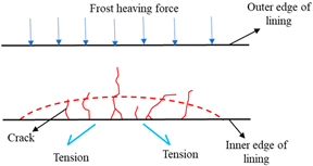
Sustainability 15 12629 i001
Shear crackThe shear stress caused by frost heave is greater than the shear strength of lining structure1. The crack gap is small, with obvious dislocation and sliding;
2. The crack is generally not serrated;
3. It often occurs at the side wall and arch waist of the lining [34,35].
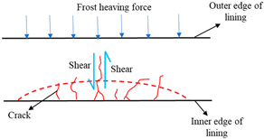
Sustainability 15 12629 i002
Table 3. Calculation model of frost heaving force.
ModelModel SketchAdvantagesDisadvantagesApplicability
Water-bearing weathering layer modelSustainability 15 12629 i003
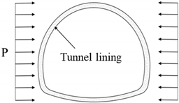
The reason why frost heave mainly occurs in the tunnel side wall area is well explained. The theoretical formulae for calculating the frost heave force are simple and conceptually clear.Frost heave deformation is only considered in terms of its development towards the lining; the elastic resistance coefficient is difficult to value; and the formula only assumes that the water-bearing weathering layer has produced frost heave with some error [47].Suitable for tunnels with broken weathering layers, high water content and small freezing depths in the seasonal freeze zone
Localized Water Frozen Swell ModelSustainability 15 12629 i004
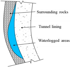
The effect of voids between the surrounding rock and the lining on lining frost heave is explained. The non-uniformity of the distribution of frost swell forces is considered.The recharge of the water source is not taken into account; there is a discrepancy between the storage space in its calculation model and the storage space behind the actual liningCalculation of local frost heave forces in hard rock tunnels only
Integral freeze-thaw circle modelSustainability 15 12629 i005
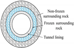
The calculation model is simple in principle, mature in theory and widely used.Calculated results are small; the analysis assumes a circular section mainly from a purely mechanical point of viewSuitable for tunnels with relatively rich pore water content in the surrounding rock and small variations in the inner diameter of the freezing circle [47]
Table 4. Characteristics and schematic diagram of different insulation measures.
ClassificationInsulation MeasuresFeaturesSchematic Diagram
Passive measuresCold insulated layer [60,61].The application of insulation on the tunnel lining structure is a straightforward and efficient method for preventing frost damage. However, it does have certain limitations in practical implementation. While it can slow down heat transfer, it does not possess the capability to completely halt the freeze-thaw cycle of the surrounding rock.
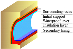
Sustainability 15 12629 i006
Cold insulated door [62]The cold-proof insulation doors can prevent cold air from entering the interior of the tunnel to a certain extent but frequently open the insulation doors and the insulation effect becomes worse frequently open the insulation doors and the insulation effect becomes worse the safety and reliability of the control technology is not easily guaranteed.Sustainability 15 12629 i007
Active measuresElectric tracing systems [63,64]The implementation of an electric tracer system proves to be an effective solution for mitigating frost damage in cold tunnels and can also serve as an emergency measure. However, it is worth noting that this solution does entail increased operating costs for the tunnel, making it a relatively expensive option. Additionally, the management of the electric tracer system can be challenging, further adding to its complexity.
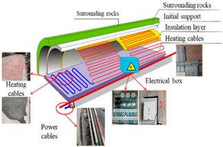
Sustainability 15 12629 i008
Ground source heat pump systems [65]The cold region tunnel ground source heat pump system is still in the initial research stage and has not yet formed a complete system. Moreover, the system has high technical requirements for installation, which will limit the application of the system when technical conditions cannot be met.
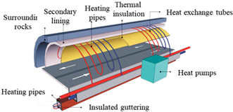
Sustainability 15 12629 i009
Air curtain system [66,67]The air curtain system can artificially control the wind speed and temperature of the air entering the tunnel to increase the temperature inside the tunnel cavity, which can reduce the severity of frost damage to a certain extent. However, this system is in the same research stage as ground source heat pumps and has not yet been applied on a large scale to insulate tunnels in cold regions.
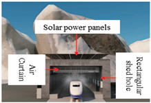
Sustainability 15 12629 i010
Table 5. Different concrete additive materials.
ConcreteAdvantagesDisadvantagesMechanism of Frost Resistance EnhancementDiagram of the Mechanism
Fibrous concrete [72,73,74]Good resistance to cracking, permeability and frostPoor construction workabilityIt can play the role of bridge, penetrate the pores in the concrete, make the connection of concrete more compact, and in the process of pullout and fracture, fiber consumes part of energy when it breaks away from the bondage of cement paste
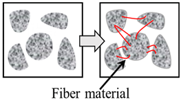
Sustainability 15 12629 i011
Nano-concrete [75]High strength, good denseness and homogeneityPoor workability and liquidityNanomaterials has filling effect: the particle size of nano materials is small and reduce the content of micropores in concrete. In addition, Nano-SiO2 can react with concrete with pozzolan to form harder gel product
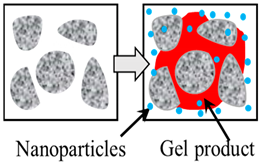
Sustainability 15 12629 i012
Air-entraining agent concrete [76]Improves the compatibility, water retention,
and the frost resistance of concrete.
Excessive addition of air entraining agent can cause a decrease in strengthAir-entraining agents can block capillary pore pathways on a wide scale, introducing a stable closure with a fine, even distribution Air bubbles buffer freezing expansion stress, reduce damage to the pore structure and improve frost resistanceSustainability 15 12629 i013
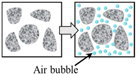
Disclaimer/Publisher’s Note: The statements, opinions and data contained in all publications are solely those of the individual author(s) and contributor(s) and not of MDPI and/or the editor(s). MDPI and/or the editor(s) disclaim responsibility for any injury to people or property resulting from any ideas, methods, instructions or products referred to in the content.

