Article

Extension of Computational Co-Design Methods for Modular, Prefabricated Composite Building Components Using Bio-Based Material Systems

by
Christoph Zechmeister
1,2,*,
Marta Gil Pérez
2,3,
Niccolo Dambrosio
1,2,
Jan Knippers
2,3 and
Achim Menges
1,2
1
Institute for Computational Design and Construction (ICD), University of Stuttgart, Keplerstraße 11, 70174 Stuttgart, Germany
2
Cluster of Excellence Integrative Computational Design and Construction for Architecture (IntCDC), University of Stuttgart, Keplerstraße 11, 70174 Stuttgart, Germany
3
Institute of Building Structures and Structural Design (ITKE), University of Stuttgart, Keplerstraße 11, 70174 Stuttgart, Germany
*
Author to whom correspondence should be addressed.
Sustainability 2023, 15(16), 12189; https://doi.org/10.3390/su151612189
Submission received: 4 July 2023 / Revised: 1 August 2023 / Accepted: 7 August 2023 / Published: 9 August 2023
(This article belongs to the Special Issue Prefabrication and Modularized Construction)

Abstract

:
Robotic coreless filament winding using alternative material systems based on natural fibers and bio-based resin systems offers possible solutions to the productivity and sustainability challenges of the building and construction sector. Their application in modular, prefabricated structures allows for material-efficient and fast production under tightly controlled conditions leading to high-quality building parts with minimal production waste. Plant fibers made of flax or hemp have high stiffness and strength values and their production consumes less non-renewable energy than glass or carbon fibers. However, the introduction of natural material systems increases uncertainties in structural performance and fabrication parameters. The development process of coreless wound composite parts must thus be approached from the bottom up, treating the material system as an integral part of design and evaluation. Existing design and fabrication methods, as well as equipment, are adjusted to emphasize material aspects throughout the development, increasing the importance of material characterization and scalability evaluation. The reciprocity of material characterization and the fabrication process is highlighted and contributes to a non-linear, cyclical workflow. The implementation of extensions and adaptations are showcased in the development of the livMatS pavilion, a first attempt at coreless filament winding using natural material systems in architecture.

1. Introduction

As the global population is increasing, urbanization is rapidly progressing. According to the United Nations (UN), by 2050, 68% of the world’s population will live in urban areas [1]. This development presents significant challenges to the building industry, which cannot satisfy the increasing demand for building floor space over such a short amount of time given current productivity [2]. On top of required productivity gains, sustainability in construction is another major challenge of our time. The construction sector and its associated activities are responsible for the production of 30% of greenhouse gases (GHG) worldwide, making the relevance of more sustainable construction evident [3]. The total GHG emissions intensity of the top five most contaminant construction industries in China, India, South Africa, Taiwan, and South Korea varies from 2.05 kg CO2e/EUR to 0.957 kg CO2e/EUR [4].
The advent of digital technologies promises to provide solutions to these challenges; however, they need to be coupled with alternative, more sustainable material systems and material-efficient ways of construction to unfold their full potential for sustainable structures.
Fiber-reinforced composites are increasingly used in high-performance applications where strength and low weight are important factors, such as in the automotive and aerospace sector or competitive sports [5]. In the building sector, their use is less common due to the necessary costly and labor-intensive formwork which limits morphological differentiation. Coreless filament winding (CFW) provides an alternative to conventional ways of composite construction. It is based on industrial filament winding but reduces formwork to an absolute minimum by mitigating any mandrel, relying solely on boundary frames between which resin-impregnated fibers span freely in space. Robotic placement of the fibers using bespoke tools allows for near-full automation of the process with minimal human intervention [6].
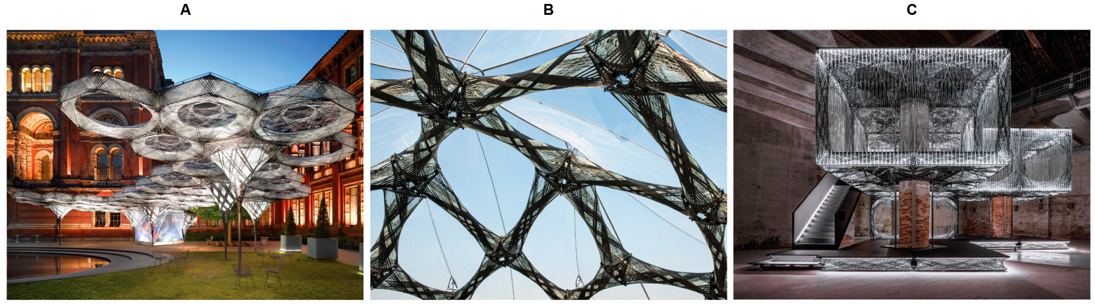
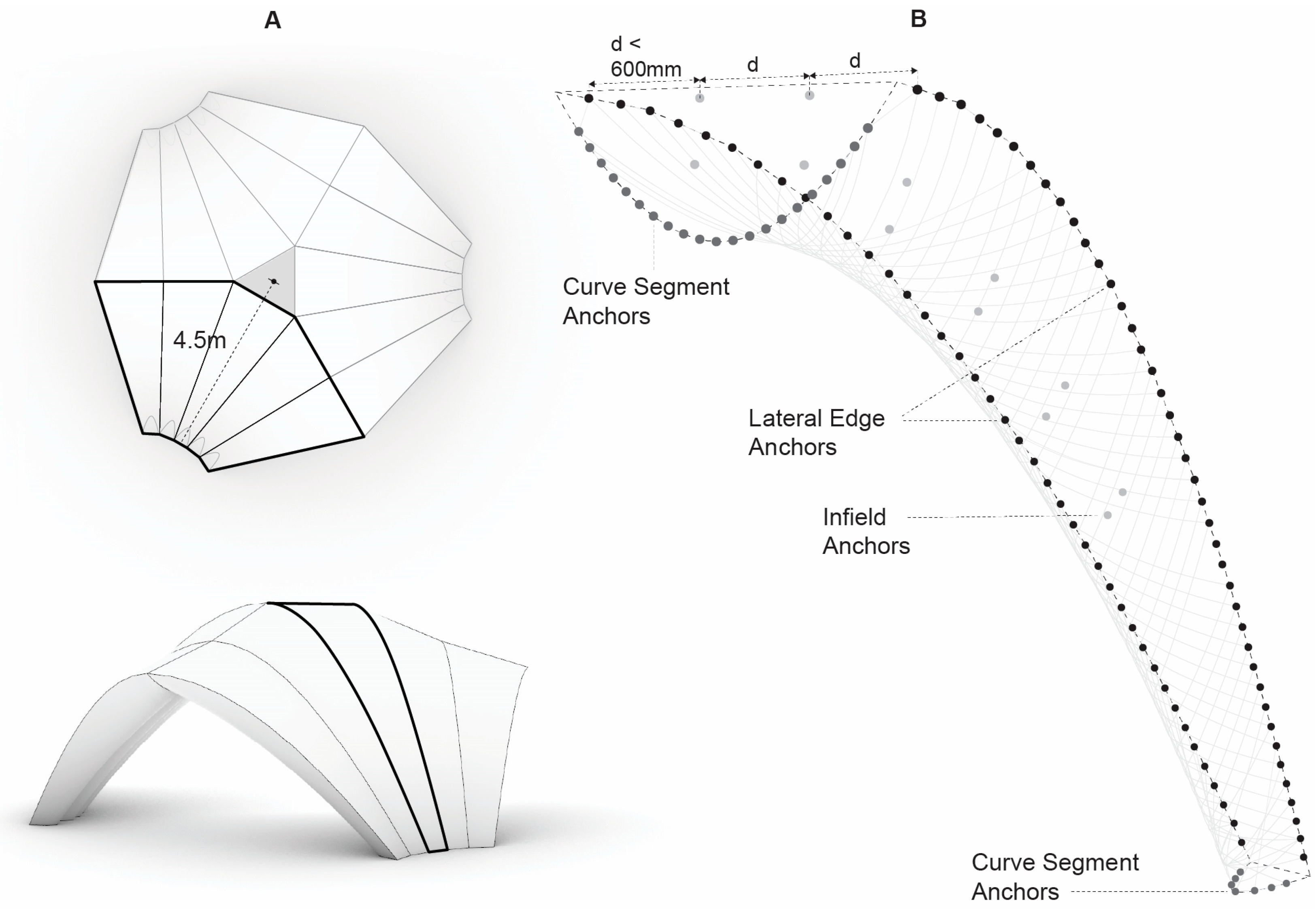
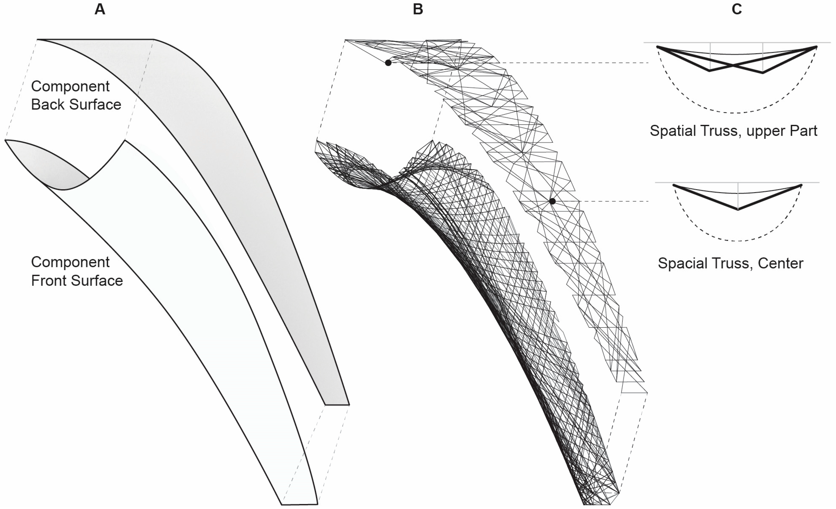
Modular construction and robotic prefabrication allow for material-efficient production under optimized, consistent conditions, facilitating quality control, leading to high precision parts, and less production waste. Modularization can be approached in two ways. In a top-down approach, a design surface is segmented, thus broken down into smaller parts (Figure 1B). Conversely, aggregating individual modules can form structures following a bottom-up approach (Figure 1A,C). In both cases, modules are not identical but morphologically differentiated, hence the importance of digital, robotic construction. Departing from mass production, a decisive factor in conventional construction, where redundancies are frequently accepted in favor of construction simplicity, robotic prefabrication allows for comprehensive customization at no extra cost. This allows for the establishment of a component design space, given boundary conditions defined by design, performance, and construction constraints, that can be explored throughout the design and evaluation process. Therefore, every component can be different, leading to unique and material-efficient structures.
At the University of Stuttgart, multiple demonstrator projects were collaboratively realized by the Institute for Computational Design (ICD) and the Institute of Building Structures and Structural Design (ITKE) across different scales. They are investigating different aspects of CFW and its application in architecture.
The Elytra Filament Pavilion [7] is a modular, lightweight roof structure composed of hexagonal cell-like components covering an area of 200 m2 (Figure 1A). All components have equal boundaries; however, their internal geometries and related structural performance are differentiated according to their specific use in the roof structure by variations of the fiber patterns. The BUGA fiber pavilion [8] extends CFW towards long-span applications. It is based on 60 carbon and glass fiber components of up to 5 m in length which together form a dome structure (Figure 1B). Seven different component types were developed, relying on minimal formwork while maximizing the fiber span between component boundaries. The Maison Fibre [9], developed for the 2021 Venice Architecture Biennale, investigates the application of CFW for multi-story structures (Figure 1C). It constitutes a modular wall and slab system, made of 30 coreless wound wall, slab, and roof components. All components are based on a 2.5 m × 2.5 m grid to comply with transportation and handling constraints and are locally differentiated through their fiber pattern according to local structural requirements. While being load-adapted, modular, and material-efficient structures, all previous implementations of CFW use material systems based on petrochemical products such as carbon and glass fibers.
The process of design and making has conventionally been separated in architectural design since the Renaissance. Computation today allows the designer to engage with materiality far beyond its selection and application to a given geometry, elevating material from being a fixed property and passive receptor of form to a generative design driver of architectural performance [10]. Materialization thus co-exists and co-evolves along with other involved multifaceted disciplines throughout the design process [11]. Alternative, material systems based on plant fibers are an important progression of CFW, and together with the material efficiency and low production waste immanent to the process, exhibit high potential for the production of sustainable building components. Plant fibers such as Flax, Hemp, or Jute fibers are readily available in Central Europe, have high stiffness and strength values, and are thus frequently used in structural composites [12]. Natural fibers are cultivated based on solar energy, and their production and extraction only use small quantities of fossil fuel energy; therefore, their dependency on non-renewable energy and material sources is significantly lower than conventional materials in composite manufacturing like glass and carbon fibers [13]. They offer several other environmental advantages like reduced greenhouse emissions and greater energy recovery, and the produced components can be biodegradable, allowing for their decomposition into carbon dioxide (CO2) or methane (CH4) and water (H2O). However, sustainability is impacted by the use of land, water, pesticides, and fertilizers used for their cultivation, leading to environmental distress. Flax fibers are commonly used in the automotive industry for applications such as interior lining. They exhibit short growing cycles of about 100 days and in Europe, they are mainly cultivated in France, Belgium, and the Netherlands. They are composed of cellulose (62.0–72.5%), hemicellulose (14.5–20.6%), lignin (2.5%), pectin (0.9%), wax, ash, and moisture (negligible content) [14]. The fibers are separated from the stems of the plants by retting and scorching to alter their properties. Pectin around flax fibers is degraded, resulting in the separation of fibers [15].
Bio-based epoxy resins offer an opportunity to further reduce the environmental impact of thermoset polymer composites. However, entirely bio-based matrices are still under development and exhibit lower mechanical properties and glass transition temperatures. To be comparable to conventional epoxies, petrochemical epoxies are mixed with bio-based parts, and their bio-based content is defined as the percentage of naturally occurring carbon in the material [16].
Life cycle analysis (LCA) is a method to comprehensively evaluate the environmental impact of a product from resources used to its end of life. It involves all stages of a product’s life, which makes it difficult to obtain accurate data and evaluate the results properly. Multiple approaches to performing LCA have been researched, leading to different results [17]. LCA of natural fiber composite shows that they offer advantages in their use and end-of-life phase, whereas the production phase contains the key to their environmental standing [18]. A comprehensive LCA is outside the scope of this research. However, global warming potential (GWP) and energy intensity (electrical energy consumption) are used as a base for the comparison of different natural fibers and resin systems.
In construction, plant fibers have been successfully used to improve the performance of building materials. Da Costa Santos and Archbold demonstrated the suitability of the use of flax and hemp fibers for concrete reinforcement [19]. Song et al. showed that cheap and widely available jute fibers can be used in cementitious composites to enhance their performance, expanding their use to areas requiring energy absorption such as earthquake-resistant construction or foundation floors for machinery [20].
The BioBuild project [21] investigated the implementation of bio composite materials made of flax and jute fibers with bio-based resins in façade systems, aiming to reduce embodied energy compared to conventional construction materials by 50%. A self-supporting façade system was developed comprising bio-composite panels and profiles using pultrusion, compression molding, and hand layup. While the project proved significant reduction of embodied energy, the employed fabrication techniques rely on bespoke dies and formwork, making them difficult to use for geometrically differentiated, load-bearing building parts.
The ISOBIO project aimed to develop hygrothermally efficient bio-based building insulation panels with 20% more insulation capacity, while reducing the embodied energy by 50% compared to conventional materials. Results such as the development of bio composites using hemp shiv and a silica matrix were water resistant and showed good mechanical performance as a non-load bearing building material with high potential as thermal insulation [22].
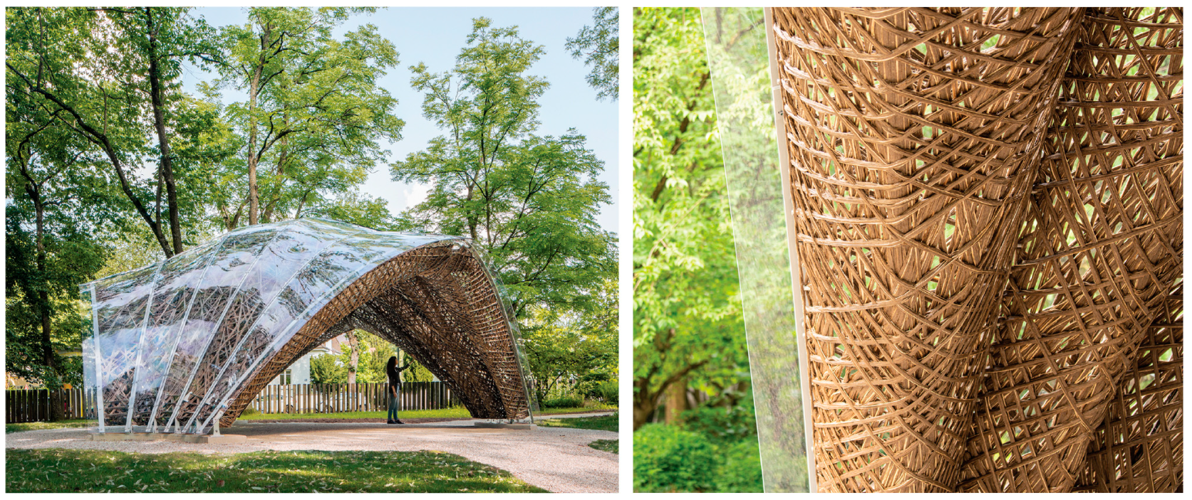
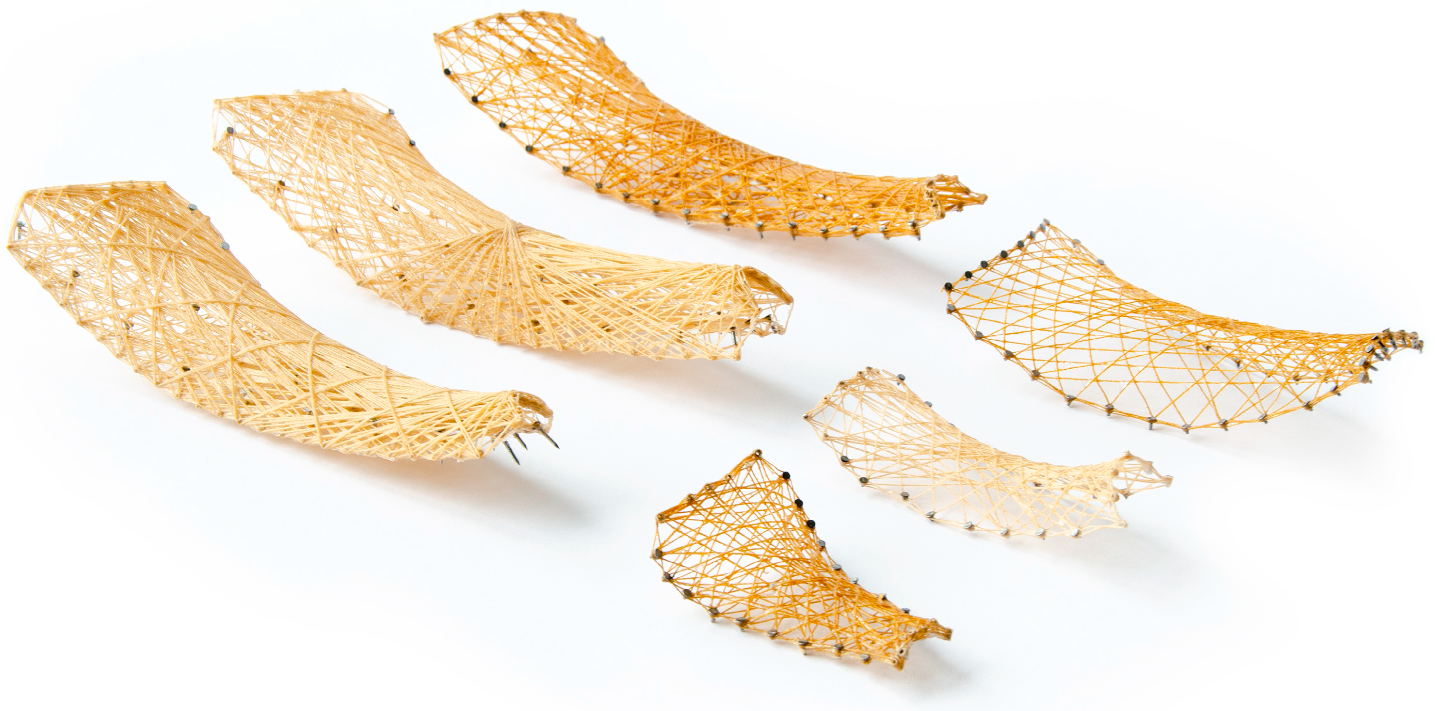
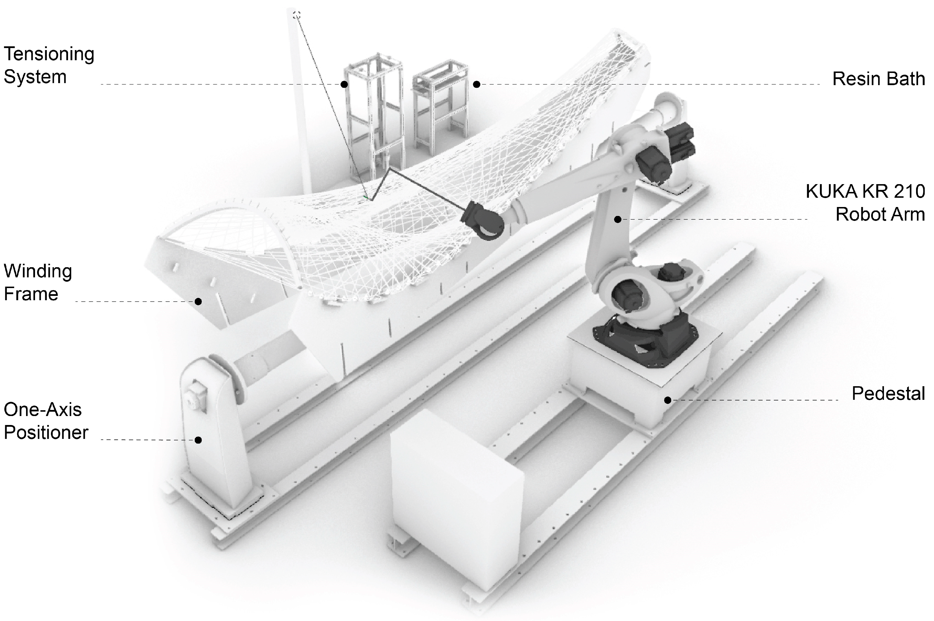
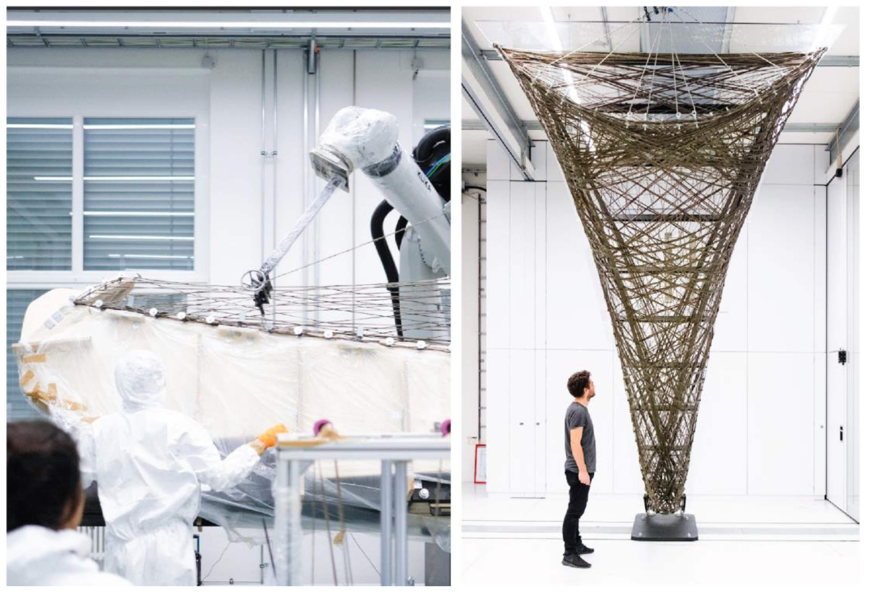
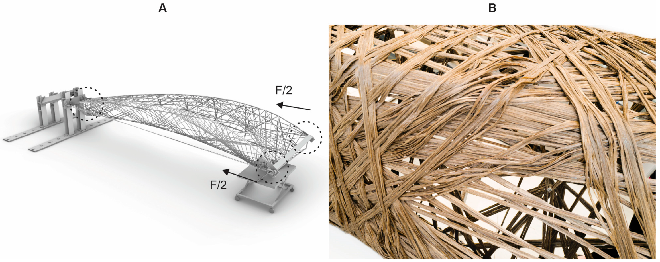
Propelled by the potential of natural fiber composites, the livMatS pavilion constitutes the first, full-scale application of load-bearing, coreless wound natural fiber composite parts (Figure 2). It leverages the opportunity of CFW to produce high-performance structures while minimizing material expenditure in a waste-free production process, and combines it with natural fiber systems to increase sustainability. The pavilion is composed of 15 components, each robotically manufactured, using continuously spun flax fibers. Ranging in length from 4.50 to 5.50 m, the lightweight building parts have an average weight of only 105 kg. The entire fiber structure covers an area of 46 m2, weighing approximately 1.5 tons in total. Complying with the German building code and structural permit requirements, the design considers various load combinations, including wind and snow loads. The radially symmetric pavilion consists of three identical bays, made of five fiber components each. The symmetric design allows for maximum flexibility, permitting different use cases and activities. With a section height ranging from 2.7 to 3.9 m above ground, the pavilion maintains a harmonious balance between the requirements of the fiber systems and the overall architectural constraints. To shelter the interior and protect the natural fibers from humidity and UV radiation, a protective skin of polycarbonate sheets covers the structure. Inside the pavilion, the components exhibit varying material densities, creating a play of transparency and opacity that establishes visual connections with the surrounding botanical garden. The pavilion was initially developed by students of the ITECH master’s program and an interdisciplinary team of researchers at the Cluster of Excellence “Integrative Computational Design and Construction for Architecture (IntCDC)” at the University of Stuttgart. The final production of the fiber components was carried out by the project’s industrial partner FibR Gmbh.
Following the ambition to make modular, prefabricated composite building components more sustainable, this research builds upon the previously developed feedback-based computational method and multi-scalar digital-physical design and evaluation toolset to model and evaluate complex fiber layups [23]. The methods integrate fabrication feedback, as well as the structural design for non-standard building systems that cannot be designed using conventional codes or simulation methods [24]. It contextualizes alternative material systems in the co-design environment and details the required extension and adaptation of methods and toolsets to enable their use in CFW. The implementation of the adaptations and extensions is demonstrated by the example of the livMatS pavilion. It serves as a case study to demonstrate the flexibility and capacity for adaptation of the developed method to accommodate not only different geometry or component typologies but also the use of alternative, more sustainable material systems, paving the way for resource-efficient, eco-friendly fiber architecture.

2. Materials and Methods

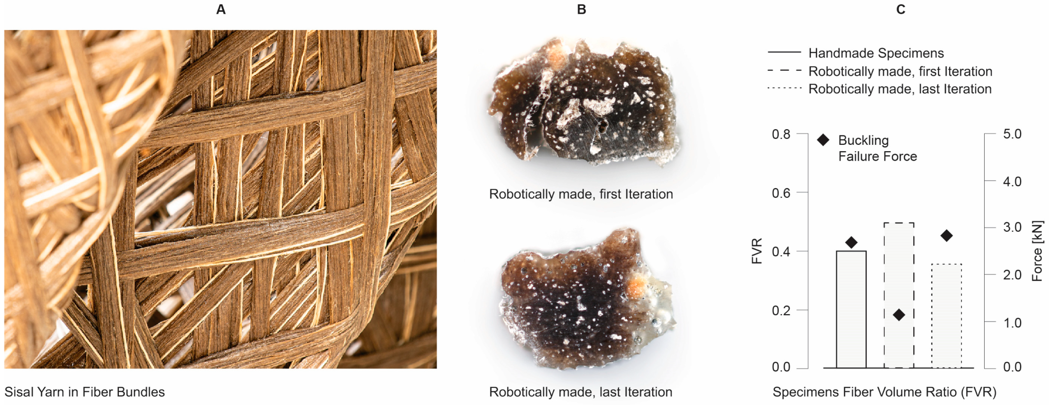
Coreless filament winding imposes several challenges on the design, manufacturing, and evaluation of composite building parts. In terms of the part’s geometry, the final shape of the composite is generated by the interaction of successively wound fiber layers during the fabrication process and might thus deviate from the target geometry. From a material point of view, a fiber-polymer composite (FPC) varies in its mechanical properties, fabrication quality and challenges, appearance depending on the raw materials chosen, fibers and matrix system, and the ratio between the two. The fiber volume ratio (FVR) can also be influenced by factors such as the handling of wet fibers in the fabrication process, the pulling force of the robot, and, in the case of pre-impregnated material, the quality of the impregnation hardware.
Considering alternative material systems based on natural fibers adds yet another layer of complexity. Natural, cellulosic fibers are hydrophilic; they absorb moisture when exposed to humid conditions, which leads to a series of issues such as low fiber-matrix bonding strength, dimensional and shape instability, or rapid product degradation. Furthermore, they exhibit lower tensile strength as petrochemical fibers and are flammable, which is specifically problematic for an application as a building component.
The interfacial bonding forces between plant fibers and matrix materials have a significant impact on the performance of the composite and are strongly linked to the chemistry of the respective plant fibers. Flax and hemp fibers generally exhibit higher interfacial forces and better adhesion with polar matrix materials such as epoxy resins than jute fibers. Jute fibers are highly lignified which reduces the number of hydroxyl groups on the fiber surface making them less polar thus diminishing interfacial bonding [25].
The evaluation of the natural fibers’ tensile strength must be carefully considered as it strongly depends on the clamping length and may lead to wrong conclusions, since with longer clamping length, fibers may fail according to the strength of the binder instead of elementary fibers [12].
Coreless filament winding must thus be approached using bottom-up, integrative methods as the material system is an integral part of the development and forms a tight-knit ecosystem with the other disciplines involved in design, evaluation, and fabrication. It departs from conventional design thinking which prioritizes geometric form and considers material as the means for its implementation. This notion is deeply rooted in architectural practice and translates into many of its different sectors where fabrication serves as the act of materializing predetermined form, and design tools allow for the assignment of different materials to preconceived spatial, structural, and constructional typologies [26].
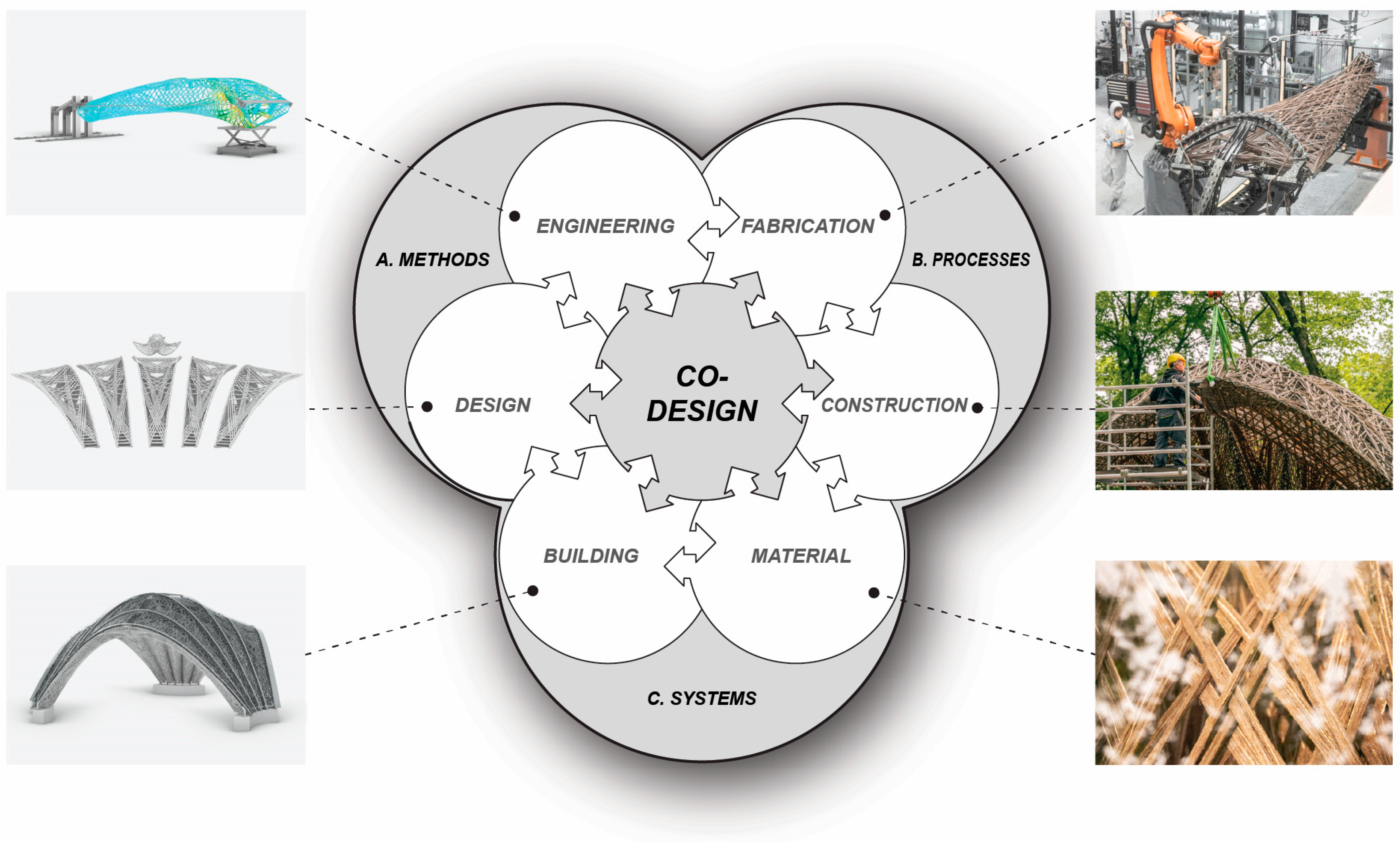
In co-design, however, computation allows for an interface between digital and physical, with material behavior and its capacities becoming the main driver in the generation of form [27]. Throughout the process of co-design, methods (design and engineering), systems (building and material), and processes (fabrication and construction) co-evolve, enabled by intertwined development cycles and constant mutual feedback (Figure 3).
The implications of utilizing alternative material systems on these interconnected development cycles of a concurrent, feedback-based co-design workflow are detailed in Section 2.1, and the corresponding extension of the multi-scalar, digital-physical design and evaluation toolset to facilitate their implementation is presented in Section 2.2.

2.1. Adaptation and Extension of the Feedback-Based Computational Design Method for the Use of Alternative Material Systems
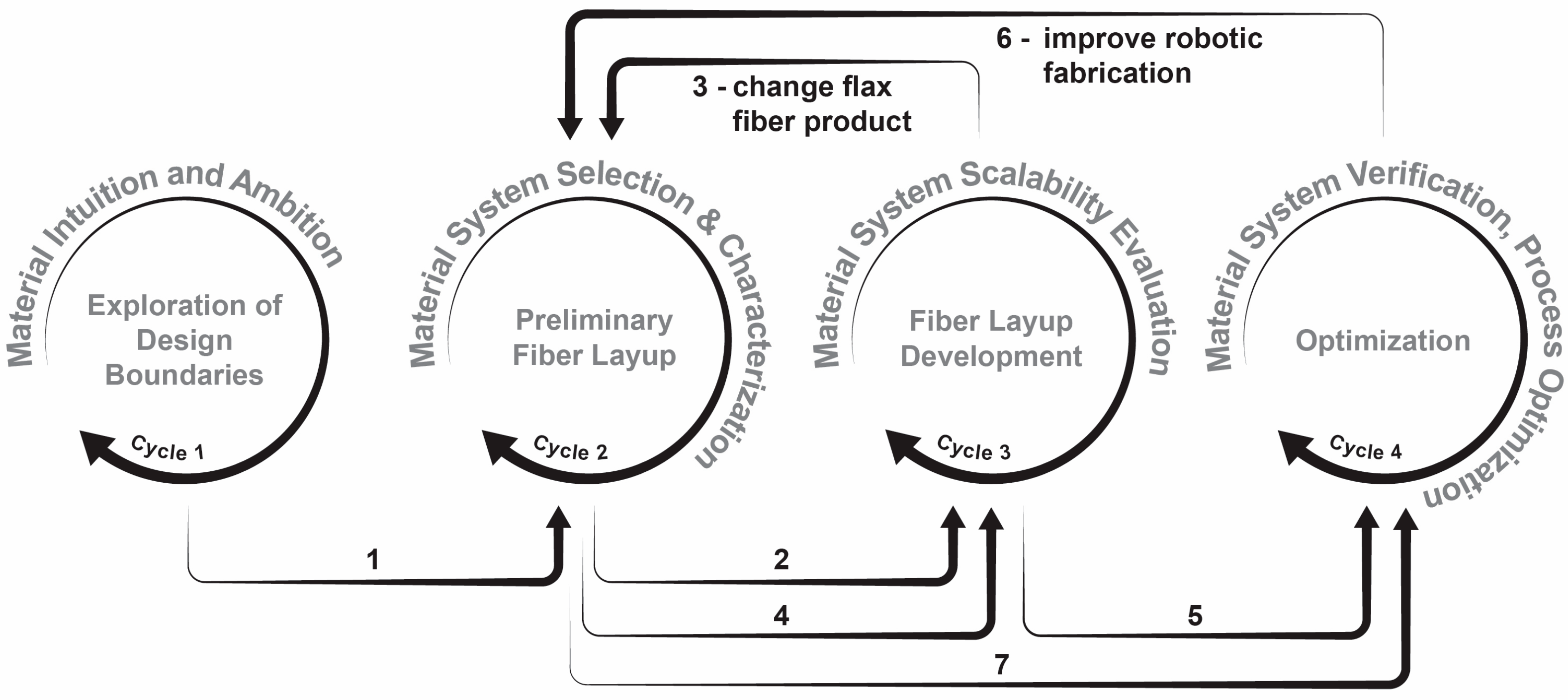
In [
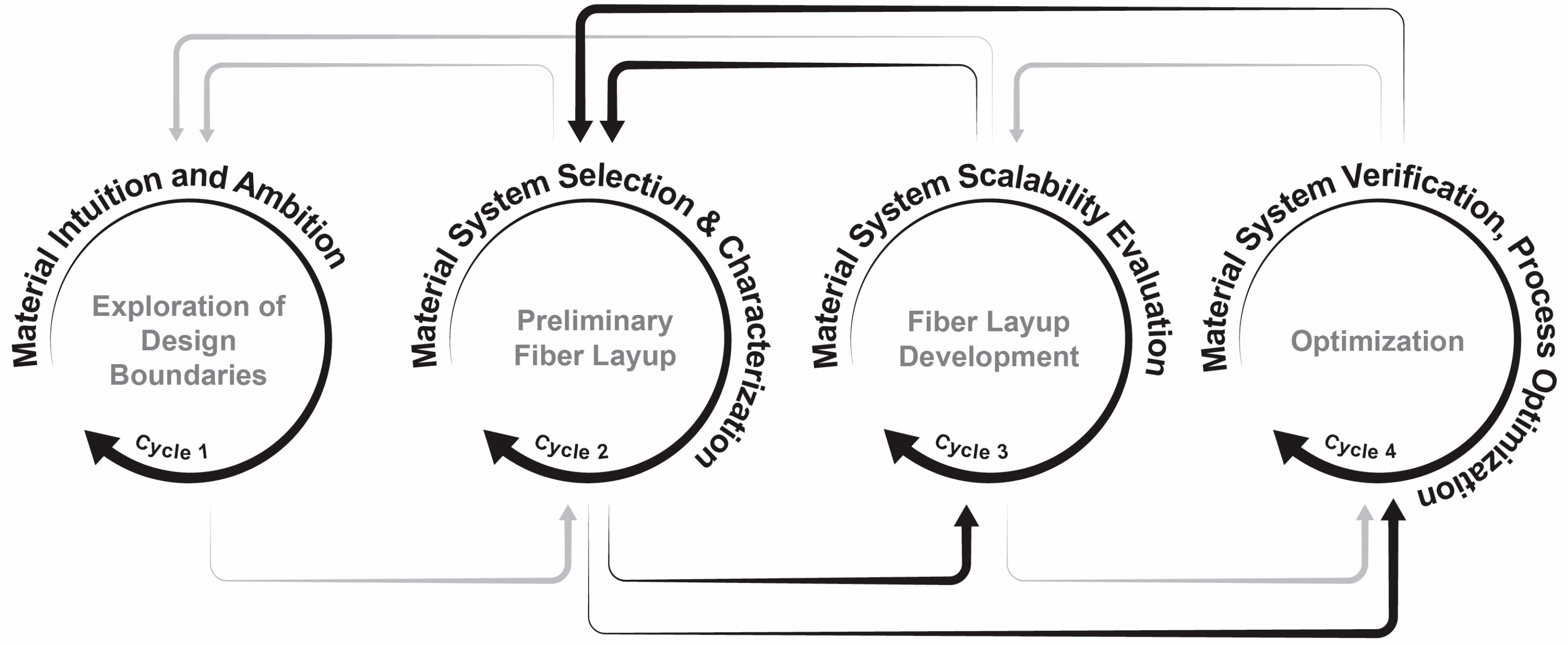
23], a feedback-based design method was introduced based on four development cycles to continuously advance methods, systems, and processes across all involved fields. The cycles are composed of a design and an evaluation part, which are tightly integrated and ensure that required performance and feasibility are maintained at all times. The design of the fiber layup is continuously developed throughout the cycles and concurrently informed by feedback from digital simulation and physical prototyping across various scales. Each of the cycles takes on a set of challenges in the development of a multi-layered, load-adapted fiber layup and is iteratively executed until the challenge is resolved and the design or performance objective is achieved. So far, these challenges assumed little uncertainty in the variability of the materials’ mechanical properties, as the material system consisted of a thermoset matrix and technical fibers. When introducing other types of alternative fibers, such as flax, hemp, or jute, the uncertainty in structural performance and fabrication parameters increases, making it necessary to emphasize the material aspects throughout the cycles and to adapt them on a methodological level to accommodate these uncertainties (Figure 4).

2.1.1. Material Intuition and Ambition (Cycle 1)

Cycle 1 marks the beginning of the fiber component design process. It starts with the design intent and finishes with the component concept. It explores the component design boundaries by establishing preliminary anchor point configurations, and investigates fiber layup typologies and structural design concepts. Ultimately, it articulates initial design ideas which are then evaluated by physical scale models.
The use of alternative material systems requires their consideration already at the beginning of the development process. Thus, specific material properties beyond basic characteristics have to be introduced. There are two ways to consider material aspects at this early design stage. The development of a material intuition is a bottom-up process where different materials are evaluated based on their suitability derived from specific requirements of the anticipated design idea. Conversely, a material ambition constitutes a top-down process where the material type is pre-determined as part of the project brief, as a result of LCA, due to project budget constraints or market conditions.
The material system significantly influences the design boundary conditions. Component dimensions, component span, connection type, and amount are determined by the structural capacity of the component, which is dependent on the mechanical properties of the material. Natural fibers exhibit lower mechanical properties than technical fibers, becoming a defining factor in the design and determining the necessary fiber pattern density and bundle cross-section dimensions. The anisotropy ratio [28], the ratio of the axial to transverse mechanical properties, is especially much lower for natural fibers. This has a direct impact on the fiber layup typologies suitable for natural material systems, as well as on the design of connections, which require denser reinforcement areas.
Fabrication constraints also influence the component’s design boundaries. In addition to limitations and parameters common in CFW as encountered in previous applications [6], the low tensile strength of dry natural fiber rovings must be considered. It imposes a limit on the tension force the robot can exert on the roving during winding, and thus, also influences the maximum fiber span which has to be considered in the design of the fiber layup and winding frame.

2.1.2. Material System Selection and Characterization (Cycle 2)

In cycle 2, the preliminary fiber layup based on design boundaries established in cycle 1 is defined. Full-scale fabrication testing to verify the fabrication feasibility of component concepts is introduced, and the material is characterized to estimate the material amount and select the material system.
The material’s mechanical properties are highly influenced by the actual fabrication process conditions, requiring concurrent feedback between fabrication setup adaptations and material characterization. Initially, a pre-selection of possible fiber/matrix candidates is established based on local availability and price. Their specified mechanical properties and relevant LCA indices are evaluated, and the most promising candidates undergo further material characterization. The resulting material capacity, together with fabrication requirements, serve as a base for selecting the material.
The fabrication setup and process need to be adjusted to work with natural fibers. Compared to carbon and glass fibers, which served as the primary material system for the initial development of CFW and on which most empirical values are based, natural fibers have lower mechanical properties and can contain defects leading to failure. The defects vary in size and location due to different diameters and variations in cellulose content [29]. Cellulose is the stiffest and strongest organic constituent in plant fibers but also makes them hydrophilic, leading to very little resistance to moisture absorption and a poor interface with matrices [30]. To lower this effect and improve the interface with matrices, plant fibers have to be dried before being impregnated with resin, adding an additional pre-processing step to the fabrication process. Another important implication of the fabrication system is the ability to monitor and actively control the winding tension. Long, technical plant fibers are especially prone to rupture as they are composed of elementary fibers using binders which will fail first due to their low shear strength [12]. Thus, tension during the winding has to be reduced but needs to be balanced with the maximum acceptable amount of fiber sag, which in turn limits the maximum length a fiber can span between two anchors. Depending on the type of natural fibers used, resin consumption is increased to compensate for higher resin absorption of fiber tapes and related bonding issues between individual rovings. This may require adaptations of fabrication hardware to increase the capacity of resin reservoirs or modification of parameters during pre-impregnation, depending on the impregnation strategy. As natural fiber rovings considerably vary in linear density, fiber handling equipment may have to be adjusted to account for it. Another issue unique to natural fibers is hairiness, which leads to an accumulation of fiber fragments over time and eventually clogs fiber handling equipment. Therefore, crucial components have to be accessible for periodic cleaning [31].
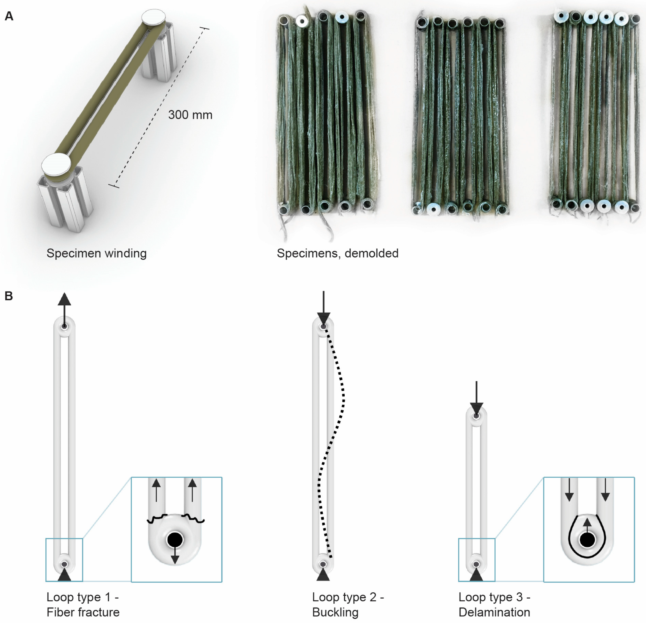
In CFW, the formation of bundle cross-sections and the quality of the bonding of individual fiber strands are influenced by the component curvature, the winding resolution, and the fiber tension. The high winding resolution, in the sense of fewer rovings per bundle, as well as high component curvature leads to better compaction, resulting in smaller cross-sections. Not relying on post-treatment such as fiber compaction or vacuum bagging, inconsistent fiber tension leads to variations in both cross-section geometry and bonding quality. Therefore, any pre-calculation of the composite’s strength and stiffness is only used as a reference, and material characterization is performed using small-scale specimens. They should be fabricated using the same fabrication setup and parameters as in later component production to represent the specific deviations and possible defects that the material system can contain [32]. At this stage, they can be used to determine failure behavior and the structural capacity relevant to the loading condition and boundaries established for the specimens. Other material parameters, such as the composite’s stiffness will be assumed using simple unidirectional formulae as the rule of mixtures [28], calculated with the computed FVR measured from the specimens and considered with a reduction factor of 0.7 to account for imperfections [33].
The material characterization results and assumptions are then used for the first calibration of the FEM and as a guide for the design [34].

2.1.3. Material System Scalability Evaluation (Cycle 3)

The results of cycle 2 serve as the base for the first full-scale physical prototype in cycle 3. It allows iterative tailoring of the fiber layup to structural and fabrication requirements. For the initial prototype, the scalability of results obtained by the material characterization on the specimen scale in cycle 2 is assumed. This assumption emphasizes the importance of keeping fabrication parameters during specimen production as close as possible to large-scale fabrication. Due to the additional uncertainties that natural materials entail regarding bonding, compaction, and impregnation quality, it is advisable to perform additional mechanical tests to verify the scalability at this stage.
The fabrication of the full-scale prototype allows for testing the adaptations of manufacturing equipment implemented in cycle 2 to accommodate the natural fiber material system. Based on the fabrication protocol and inspection of the final results, fabrication issues can be identified, and solutions developed. These can either result in further adaptations of the equipment or changes in the fiber pattern. If issues related to the material system cannot be resolved at this stage, the material choice needs to be reconsidered; thus, cycle 2 and consecutively cycle 3 have to be reiterated until proper scalability from specimen to full scale is ensured. Redefinition of the material system and the resulting loopback to cycle 2 can also be triggered by factors external to the component design like material price or lack of availability in quantities, required to complete the project.

2.1.4. Material System Verification and Process Optimization (Cycle 4)

In cycle 4, the first pre-series component is produced and structurally evaluated to refine the fiber layup and optimize the material amount and fabrication parameters. It allows the verification of the useability of the material system and the investigation of its boundaries given a specific fiber layup while maintaining necessary safety margins. Structural testing of the pre-series component allows obtaining real-word cross-section dimensions, FVR, and component stiffness values, to calibrate the FEM accordingly [35].
Fabrication parameters are refined and tweaked, and any issues specific to the material handling or impregnation of natural fibers are resolved. The winding process is optimized for fabrication efficiency, where depending on the natural material system additional measures have to be considered, such as equipment cleaning due to accumulated fiber fragments, or more frequent exchange of resin reservoirs related to increased resin consumption.
In case of fabrication problems and structural underperformance of the material system during full-scale testing, a loopback to cycle 2 is triggered where the material system is re-characterized and adjusted, and further fabrication equipment adaptations are implemented. Structural issues at the material level can be exponential with natural fibers as possible scalability issues are more likely to happen. Especially if the fabrication setup was changed in cycles 3 and 4, it is possible that the results of the small-scale specimens in cycle 2 are not representative anymore, and therefore, need to be repeated to represent the properties and structural behavior of the full-scale component.
If structural testing is successful in cycle 4, the maximum internal forces at the fiber layup level can be conferred to different component types after the FEM is calibrated, thus allowing for their optimization without being prototyped and separately tested.

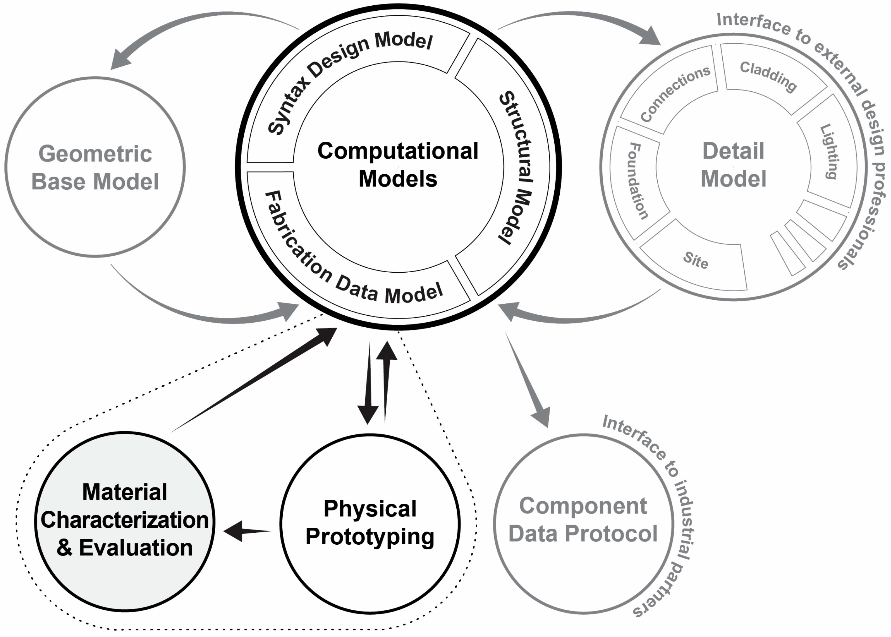
2.2. Extension of Multi-Scalar, Digital-Physical Design and Evaluation Toolset

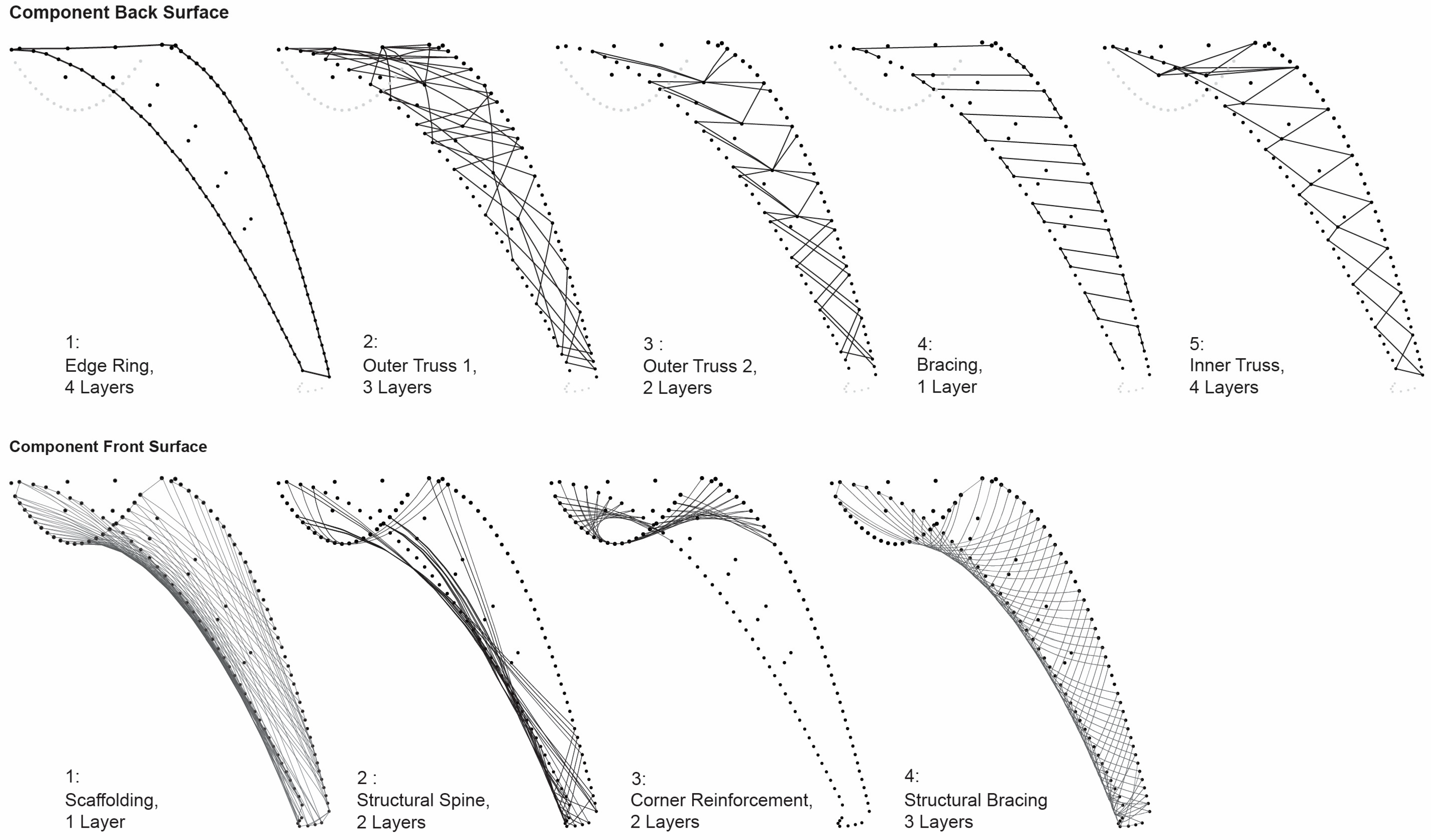
To holistically describe complex fiber layups, multiple models with different resolutions are linked and combined into one modeling approach. It comprises a geometric base model, computational models, and a detail model. The geometric base model defines the component type, count, and typology, and establishes the base coordinate system. The computational models are the central data node, and handle all geometric and semantic data, while the detail model depicts the interface to external design professionals. For geometrical and associative modeling, Rhinoceros 3d 7 and Grasshopper Build 1.0.0007 are used and extended with custom C# scripts and bespoke Grasshopper components [36]. However, the proposed toolset is largely independent of software packages and could also be implemented in different software given similar functionality.
To encapsulate the increased variability of mechanical properties of alternative material systems based on natural fibers, material characterization, and evaluation need particular emphasis and are considered as a dedicated mechanism to inform the computational models (Figure 5). Initial assumptions on material performance based on experience and existing material data, which inform the computational models, mature throughout the process, continuously updated by physical prototyping and testing under consideration of fabrication parameters.
Material characterization and evaluation have implications on each one of the computational models and become defining factors for triggering loopbacks in case of insufficient material performance (see Section 2.1). They are translated into the syntax design model by directly influencing the design of the fiber patterns as well as the pattern sequence. The fabrication data model is informed by utilizing layer amounts describing how many times a pattern is repeated as well as how fibers are hooked around the anchors. Ultimately, information derived from material characterization is used to calibrate the FEM and to inform about limitations related to specific failure behaviors found during small-scale testing.

3. Results and Discussion

The livMatS pavilion serves as a case study to evaluate and showcase the applicability of the method developed in [23], focusing on the required extension and adaptation to accommodate alternative material systems based on natural fibers. The following section differentiates between the implementation of the feedback-based design methods on an overarching level and the specific extension and adaptations of development cycles to design and evaluate fiber layups using natural fibers. In Section 3.1, the changes and enhancements of development cycles and feedback loops introduced are mapped out and related to their implementation in the design of the livMatS Pavilion. Section 3.2 delves into the individual cycles and details the specific implications of alternative material systems.

3.1. Implementation of Feedback-Based Design Methods

Figure 6 provides an overview of the specific workflow used in the development of the livMatS pavilion, derived from the generic definition of the feedback-based design method. The most significant deviations from a linear progression through the cycles can be observed in cycle 3 and cycle 4. Both are related to the material system and in both cases, a loopback to cycle 2 is triggered to recharacterize the material, albeit due to different reasons. In cycle 3, the flax fiber material was changed to a different product, which therefore, needed to be recharacterized, whereas in cycle 4, the structural performance of the material system revealed robotic fabrication problems that required equipment and process adaptations (Figure 6).

3.2. Project-Specific Application of Development Cycles

The following sections provide detailed explanations of the adaptation and extension of the cycles to facilitate the development of the livMatS Pavilion.

3.2.1. Exploration of Design Boundaries Established by the Natural Material System (Cycle 1)

The definition of the design intent was derived from the requirements articulated by the client, who envisioned a fibrous shell structure situated in the botanical garden of the University of Freiburg. It included the use of natural fibers to correspond to the client’s research on material systems inspired by nature and aligned with the research agenda of the associated design studio project.
The boundary conditions for the design of the component are established by several factors, as either top-down or bottom-up constraints. The material system is the factor with the most profound impact and can in this case be considered a top-down material ambition. Other factors superimposed on the component are its specific case of use, the anticipated life span, and the global morphology. The life span was chosen to be a minimum of five years, where the structure is supposed to be used as an outdoor lecture room by the Cluster of Excellence livMatS at the University of Freiburg. The global morphology of the component was derived from the client’s ambition to build a shell-like enclosure, composed of three radially arranged clusters of five components and one additional keystone element in the center.
These top-down constraints are combined with a set of bottom-up constraints such as sustainability aspects, fabrication limitations, and structural performance linked to the material choice. The material choice commenced with the investigation of available, alternative natural fiber materials, such as flax, hemp, or jute fibers, and the comparison of their properties to carbon and glass fibers (Table 1). According to the literature, the mechanical properties of raw flax fibers are superior to other possible natural fiber candidates, and its tensile strength approaches one of glass fibers [30]. Hemp fibers show similar elastic modulus but exhibit much less tensile strength, while jute fibers have worse mechanical properties in general. For the resin system, conventional oil-based epoxy previously used in other CFW applications was compared to alternative bio-based epoxy. Bio-based epoxies present similar or slightly lower mechanical properties than oil-based resins, but with lower LCA indexes, making them worth considering.
As for sustainability aspects of the fibers, local availability, energy intensity, and GWP of the material were considered. Flax fibers were chosen, as they were readily available, exhibit good mechanical properties, and have low GWP and energy intensity compared to carbon fibers (Table 1). Other natural fibers reach comparable values; hence, local availability and suitability for the CFW process became decisive factors for material pre-selection. The resin system was left open at this stage, to test fabrication suitability and mechanical performance of small-scale specimens later in cycle 2.
Fabrication limitations influencing the component’s design space are mostly related to the lower mechanical properties and the material’s behavior during impregnation and winding. Tension during winding and the fiber span between anchor points are limited due to the low tensile strength of the material. A resin system with an extended pot life was another constraint, necessary to enable the fabrication of large-scale parts with dimensions between 4.5 and 5 m, as the fabrication process cannot be interrupted and has to be contained within one working day.
The structural concept is based on the selected flax fibers and explores the arrangement of components as three-hinged arches. The main connections between components were placed on both sides at the top using steel plates. The foundations are also pin-supported with steel plates, avoiding the induction of bending moments into the components. Anchor points along the sides were required as lateral connections, and to reduce the fiber span between anchors. Based on preliminary results from a simplified FEM, a component span with a maximum of 5 m was assumed to be feasible from a structural point of view (Figure 7A). To distribute the roof loads, the skin had to be connected to the components with a maximum distance of 600 mm between induction points. Therefore, internal supports in the upper part of the component were required (Figure 7B).
Based on these requirements, different anchor point configurations and resulting component shapes were explored and evaluated digitally and by physical scale models. The result was a tube-like geometry, with an anchor point configuration consisting of two parallel edges with equally spaced anchors and a series of elevated infield anchors in the upper part to support the skin. To wind the high-curvature, front part of the component, additional anchors were placed at equal distances along two curve segments at the short ends (Figure 7B).
The established component design space was explored by testing preliminary ideas of fiber patterns for the mono-material flax fiber component (Figure 8).
The tube-like geometry of the component was divided into a front and back surface (Figure 9A). All fiber layup typologies identified in prior research based on carbon and glass fibers, like lattice, grid, and truss-like fiber formations [23], can generally be used with natural fibers, considering some limitations. Truss-like fiber formations, for example, should not be used in high-compression areas due to lower stiffness and possible early buckling or delamination failures. Lattice formations are better suited to withstand this type of force. Therefore, the front surface was conceived as a lattice-like layup, leveraging the higher surface curvature to facilitate fiber interaction. In the back surface of the component, a spatial truss was considered as a possible layup typology to establish the interface to the skin (Figure 9B,C). In terms of appearance, the boundaries between typologies become increasingly blurry as there is less visual separation between individual fiber patterns when using only one material type; hence, the lattice-like overall aesthetics.

3.2.2. Preliminary Fiber Layup (Cycle 2)

Based on the design boundaries established and subsequent design explorations using physical models and small-scale prototypes in cycle 1, the initial fiber layup was developed (Figure 9B).
All existing fiber layup typologies were used in the livMatS pavilion according to specific structural, fabrication, and aesthetic requirements. The back part of the component was wound first and creates a spatial truss nested within the component (Figure 9C). It comprises two outer truss layers, a bracing layer to push them together and improve fiber interaction, and an additional inner truss to add structural depth and support the inner connections of the building skin. This strategy allows the truss-like back surface to receive and distribute snow and wind forces from the roof in tension. The front part exhibits significantly more curvature in the transverse direction created by the combination of a dense scaffolding surface, a truss-like longitudinal fiber spine with long fiber spans, and multiple reinforcement grid formations on top, structurally reinforcing the component’s surface and reducing buckling length of the spine. The material amount was conservatively estimated with higher safety margins using FEM, considering the small-scale specimen results.
To test the fabrication of preliminary fiber patterns at full scale, several fabrication challenges related to the use of natural fibers needed to be considered. The prototyping setup used builds upon previous projects [5] and comprised an industrial robot arm placed on a pedestal combined with an additional one-axis positioner to facilitate the reachability of anchor points, which otherwise would exceed the robot’s working envelope. A dip-type resin bath was used together with a self-compensating tensioning system to accommodate the natural fiber’s sensitivity to tension peaks and to avoid sagging fibers (Figure 10).
However, the mechanical, gravity-based tensioning system proved to be problematic as it had insufficient capacity to take up the slack generated by the robot motion during the winding of long-span fibers. This problem was later attenuated by carefully implementing scaffolding patterns and reducing fiber span wherever possible. Another challenging aspect was the impregnation of natural fibers. As explained in Section 2.2, flax fibers need to be preprocessed before impregnation. At the time of prototyping, this was not yet considered and led to problems in fully impregnating the rovings to their core. The selection of the fiber product and type significantly contributes to the impregnation quality as well. Flax fiber rovings with 2000 tex and a low twist of 20 turns per meter (TPM) were first selected. The low twist increases the tensile strength at the dry state, leading to a strength-at-break of 250–300 N, while untwisted flax fiber tapes can only take 30–50 N. This is beneficial for robotic filament winding as it will avoid fracture of the rovings during winding. However, the twist decreases permeability and prevents resin from penetrating the core of the yarn, making impregnation more difficult [37].
To understand the impregnation quality and its influence on the mechanical properties, the flax fiber low-twist yarn was characterized using small-scale specimens (Figure 11A–C). The initially used star-shaped specimens exhibit bundle cross-sections of 20 mm, equal to previously made carbon fiber ones, fabricated for a different project [38]. To achieve identical cross-sections, the amount of simultaneously wound rovings and the number of layers were adjusted. The resulting specimens differ slightly in weight with the carbon fiber reference being the heaviest, followed by the flax fiber sample with bio-based epoxy, and the flax fiber and petrochemical epoxy combination (Figure 11D). The objective was to evaluate the initial fabrication setup, the structural performance, and LCA indices in comparison to previously used carbon fibers.
The results were promising as no fabrication problems occurred at this scale. The structural capacity of the flax fiber specimens was about 40% of the carbon fiber ones based on the forces registered during the test. Considering the performance per kg to account for the differing weight of the specimens, the performance gap is reduced and the flax fiber specimen with petrochemical epoxy achieved 54% of compression forces (Figure 11D). The GWP per kg of material of the flax fiber specimens is about 20% lower (Figure 11E), and the energy intensity during production is reduced by 40% (Figure 11F). The main contribution to GWP and energy intensity originates from the resin system.
During this test, a suitable bio-based resin system was tested as well. The molecular structure of the resin is bio-based at 51%, the resulting bio-based content of the mixture, however, is lower, as it also depends on the hardener. The combination of flax fibers and bio-based resin resulted in lower structural performance due to impregnation problems, leading to increased LCA indices. Energy intensity is only reduced slightly compared to the flax fiber and petrochemical specimen and the GWP is even higher due to lower structural performance and higher weight (Figure 11E). At this early stage of the project, considering fabrication and structural characterization results, the low twist yarn thus seemed ideally suited for robotic CFW. The resin system, however, was not changed to bio-based epoxy to avoid further fabrication issues. The developed preliminary fiber layup and initially selected material system serve as a point of departure for the subsequent detailed development of the fiber layup.

3.2.3. Fiber Layup Development (First Loopback—Cycle 3/2/3)

A first full-scale prototype was produced to provide feedback on the scalability of the results of the material characterization and to evaluate the preliminary fiber layup (Figure 12). Extended winding times were expected so the material amount was limited to one layer per pattern to not exceed the material’s pot life and to save material resources.
The experienced winding times were longer than expected due to problems with material impregnation and the tensioning system. The extended fabrication duration led to increased viscosity of the resin and partial curing of previously wound layers, resulting in reduced fiber interaction and limited ability to post-tension fiber rovings by pulling forces exerted by subsequent ones. Another observation was unequal material distribution on anchor points which led to overflowing anchors in high-density areas, while other anchors were underpopulated. Problems like overflowing anchors are a common occurrence in early CFW prototypes and can be addressed by modifying respective fiber patterns. The inconsistent impregnation, however, has more implications. The twist in the flax fibers was identified as a likely reason for this problem, as it occurred in the full-scale prototype. The impregnation problems, together with other factors like limited availability and high costs compared to other natural fiber materials, led to the conclusion to reconsider the choice of fiber material, thus going back to cycle 2, and repeating the small-scale material characterization.
Simple, hand-wound loop specimens spanning between two anchor points were produced for two different types of flax fiber material (Figure 13A); the low-twist yarn, initially used for the full-scale prototype, and a new, flat fiber roving. The specimens were fabricated using oil-based epoxy resin and tested under tension and compression (loop type 1 and 2, Figure 13B), to investigate fiber fracture and buckling failures. The tension test resulted in a slightly higher performance of the low-twist yarn in comparison to the flat roving, related to the higher mechanical properties of the raw fiber material. However, the buckling failure force of the flat roving was 2.4 times higher than the one obtained by the low-twist roving. This difference in behavior can be associated with better impregnation and bonding between the layers of the flat roving, as buckling is highly driven by the resin-fiber linkage. After this first round of investigations, the flat roving was further tested with different bio-based resins, intending to find a more sustainable matrix system for the pavilion. The investigation was carried out with a loop specimen of type 3 (Figure 13B), to test the transverse delamination of the composite, which is fully dependent on the impregnation, bonding, and performance of the resin. The results showed that bio-based resins still underperform in comparison to oil-based epoxy, both in failure force and stiffness. As a result of this material characterization round in cycle 2, the flat fiber rovings with oil-based epoxy were selected.
Moving forward to cycle 3 again after the reconsideration of the material system, the new fiber material also impacted the fiber layup. The selected flax fiber tapes have an increased linear density of 2400 tex compared to the 2000 tex of the previously used low-twist yarn. This means that more material is deposited given an equal count of simultaneously wound rovings, thus, the number of rovings had to be reduced from 8 to 6 to approximate the initially estimated material quantity. Based on observations from the initial prototype and considering the new results of the small-scale material characterization and subsequent calibration of the FEM, cycle 3 was repeated. Several fiber patterns were reconsidered, and material quantities were adjusted. From a fabrication point of view, the patterns were optimized to improve fiber interaction, while the calibrated FEM allowed identifying areas that required specific reinforcement. Long winding patterns could therefore be reduced to local reinforcements, decreasing the total length of the layup. The change of fiber material and fiber layup optimization resulted in a reduction to 66% of the fiber weight compared to the original layup.

3.2.4. Optimization (Second Loopback: Cycle 4/2/4)

With the material system selected and fiber layup developed, pre-series components could be produced at the premises of the industry partner before the actual production of the building parts began. In total, a series of three pre-series components were manufactured and structurally tested to serve as a base for further optimization of the fabrication process, the fiber layup, and the verification of the material system.
The structural test was conceptualized to load the component in compression using their upper connectors while supported at the foundation brackets as in the final design. The first pre-series component test revealed unexpectedly low performance, as it failed at the load induction points by delamination (Figure 14A). As the forces leading to failure were less than a third of the ones experienced with the small-scale, type 3, loop specimens, the weak results seemed to be linked to fabrication problems related to fiber impregnation. The pre-series component also presented visible areas of sagging fibers and malformed bundles produced by the loss of tension during winding, and the deformation of previous layers due to the low stiffness of the fiber material (Figure 14B).
To analyze the problem and to isolate the issues in the fabrication process, another loopback to cycle 2 was decided to again produce small-scale specimens, this time using the fabrication setup of the industry partner. The newly produced specimens could then be compared to existing data derived from the hand-wound samples previously produced (see Section 3.2.3), therefore allowing for isolation and assessment of fabrication issues and improvements. To improve fiber impregnation and mitigate sagging, different adjustments were made over three iterations. Regarding impregnation, the resin bath and end-effector were modified. However, these modifications alone proved insufficient to retain enough resin, so an additional layer of resin coating had to be applied after winding. To reduce the sagging of fibers, a sisal yarn was introduced and embedded in the fiber bundle before impregnation to take the tension forces exerted by the robot (Figure 15A). This allowed winding with increased tension and eventually solved the issue of malformed bundles. The first iteration of the robotically wound specimens (Figure 15B,C) showed a very high FVR in comparison to the hand-wound specimens made earlier (about 10–15% less resin). Although this first iteration already included the sisal yarn, solving the tension problem, it still showed visible bundle separation and large dry spots where fibers were poorly impregnated due to the lack of resin. Therefore, two more iterations were necessary to achieve proper impregnation. In the final iteration, the FVR was lowered, indicating better impregnation, visible in the cross-section cut shown in Figure 15B, finally achieving comparable performance to the hand-wound reference (Figure 15C).
Since the structural target performance was achieved at the scale of the specimen due to the implemented fabrication equipment and process adjustments, the development of the fiber layup could be finalized (Figure 16). Subsequent pre-series production proved that the implemented changes derived from the specimen were successful, and the structural test showed improved results.
The FEM was recalibrated during the last two iterations of full-scale testing, enabling the fiber layup of the component to be further optimized, and material amount reduced.
Departing from the preliminary fiber layup developed in cycle 2 (Figure 17A), cycle 3 (Section 3.2.3) yielded significant improvements and material reduction due to digital FEM feedback (Figure 17B). This development was based on general adjustments derived from process requirements in CFW, and led to a significant reduction of fiber weight, while also reducing the internal compression forces (Figure 17D). The maximum axial forces were derived from FEM and the fiber weight was calculated by the length of the fibers and the fiber tex. In cycle 4, in contrast, the physical observation of the material system’s behavior under real loading allowed for changes in the fiber layup, specific to the actual implementation of natural fibers (Figure 17C) The layup making up the front part of the component was changed significantly. The structural spine pattern was adapted and extended to incorporate additional anchor points at the bottom, reinforcing the foundation area. Changing the pattern from a truss-like to a grid-like formation, allowed it to cover more surface area (Figure 17C), providing better support for subsequent layers, and helping with the sagging problem. It also helped to remove the formerly separate bracing layer which influenced the sagging of previous patterns. It was also observed that the repetition of several layers within the same pattern produced sagging of the previously wound layer, as the tension increased, and formerly wound layers deformed. Therefore, the remaining structural bracing layer wound last was reconsidered with a different, more continuous pattern covering more surface area, but with fewer layer repetitions, just enough to fulfill the structural performance requirements.
The implemented optimizations in terms of improved continuity of the patterns and material reduction allowed for the component to be produced in one working day while the structural target performance was achieved. Owing to the optimized fiber layup, the final structural test achieved more than 2.5 times the design load, and the final components could successfully be manufactured. The changes of the fiber layup in cycle 4 only slightly reduced the fiber weight while maintaining the internal force levels in comparison to the changes made in cycle 3 (Figure 17D), but were necessary from a material system point of view to adapt CFW to the design requirements of natural fiber materials achieving optimal structural performance.

4. Conclusions and Outlook

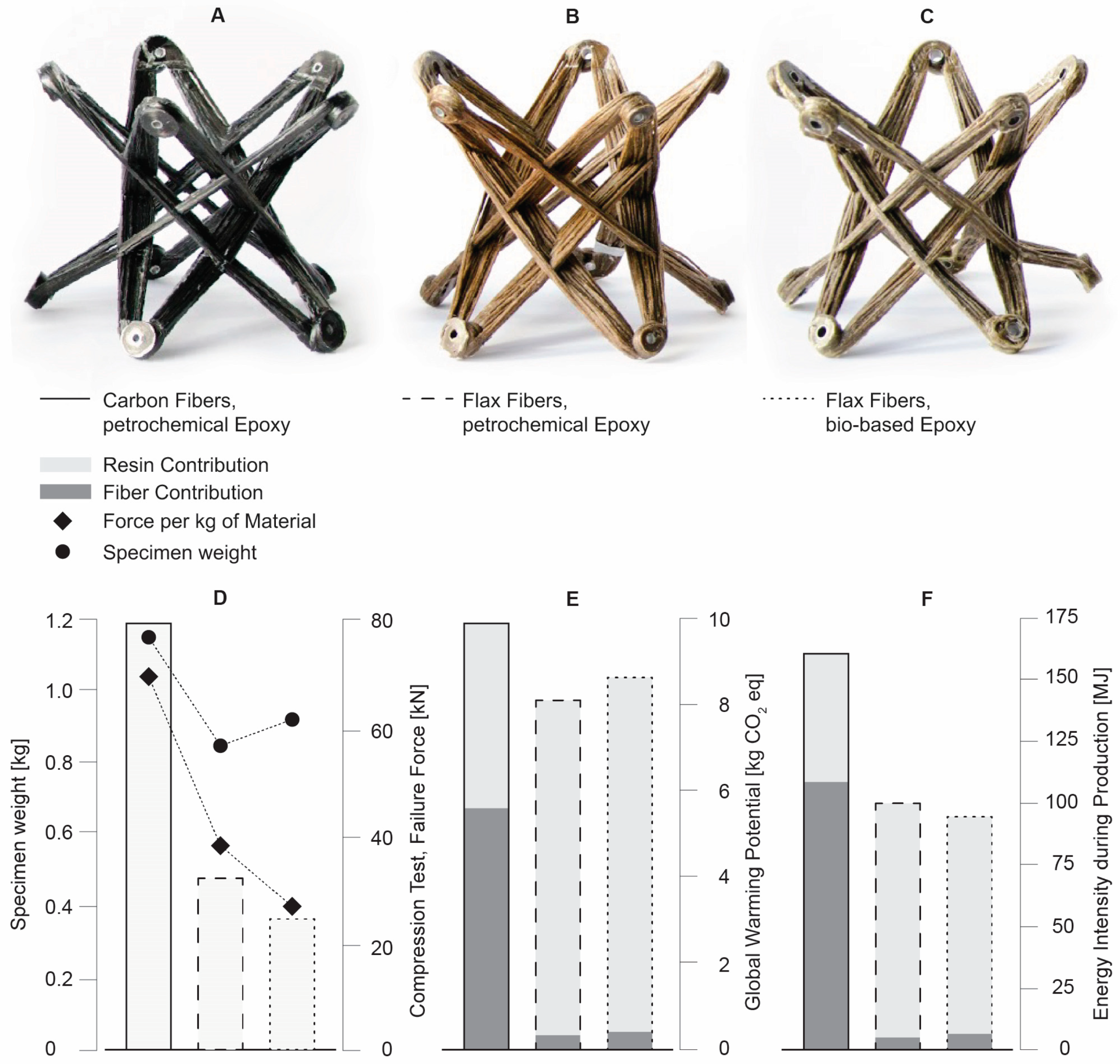
CFW allows for waste-free and economical prefabrication of modular, lightweight, high-performance building parts using materials like carbon and glass fibers. While carbon and glass fibers allow for material-efficient structures, their energy intensity and GWP are high. Replacing petrochemical materials has the potential to lower environmental impact, considering their specific application and reasonable balance between the material amount and structural requirements. Alternative material systems add another layer of complexity to the design and evaluation of composite building parts. To account for the uncertainties introduced by the variability of mechanical properties of natural fibers, previously developed methods, and tools have to be extended and adapted to consider and emphasize material aspects.
Co-design, as a flexible, conceptual framework for interdisciplinary collaboration, embraces material-driven bottom-up development of architectural building components. In contrast to conventional hierarchical and linear design chains, it allows for material behavior and its capacities to become a driving factor in the generation of form where computation acts as an interface between digital and physical. Material capacities are considered from the outset and become the main drivers in the development of methods, systems, and processes, allowing for their concurrent evolution.
The existing multi-scalar digital-physical design and evaluation toolset is extended by adding material characterization and evaluation as a dedicated mechanism to inform computational models, continuously updated by physical prototyping and testing. The variability of mechanical properties can thus be considered in the design and evaluation toolset and influences syntax design, structural, and fabrication data models.
To be used with alternative material systems, the previously developed, feedback-based design method based on interconnected development cycles is adapted at several points. The integration of material investigation into the design and evaluation process needs to start from the very beginning to determine design space boundaries. Material ambition and intuition are differentiated and considered at this early design stage. Material characterization using small-scale testing in cycle 2 is highlighted as an important hub for design decisions, determining the pre-selection of material systems, and allowing to get early information on material performance and properties. The scalability of the small-scale investigation is evaluated based on initial full-scale tests of the material system and fabrication setup. Verification and process optimization ensure the reduction of material expenditure and structural reliability of the composite component.
The global workflow of the feedback-based design method is adjusted by acknowledging cycle 2 as a destination for further loopbacks to iterate on the material selection and characterization at a specimen scale until proper material scalability and fabrication feasibility are ensured. This demonstrates the importance of a non-linear, integrative workflow as the material system’s mechanical properties depend on proper fabrication execution and setup. Therefore, loopbacks to cycle 2 can also happen at later stages when fabrication infrastructure is changed, such as in the case of production handover to an industry partner, demonstrated in the case study (Section 3.2.4).
The use of LCA indicators such as energy intensity and GWP allows for the assessment of environmental aspects and impacts of the component’s life cycle. It enables the verification of the relation between material expenditure and structural performance requirements of different material options. The investigation of mechanical properties and LCA indices as well as subsequent material characterization to determine the material capacity given the specific fabrication conditions provide a base for the selection of suitable material systems. The development of methods to integrate comprehensive LCA into the design and evaluation workflow is currently ongoing and is expected to be an important step to evaluate design candidates and to better determine the sustainability of designed structures.
Bio-based resin systems offer opportunities to further reduce the environmental impact of natural composites. They are commonly mixed with oil-based parts, and their bio content is defined as the percentage of naturally occurring carbon in the material. Different bio-based resins have been tested in the presented case study, however, all of them exhibited problems regarding their processability with CFW, such as too short pot life, and impregnation issues. The lower structural performance compared to carbon fibers and petrochemical resin is closely related to fabrication issues and is expected to improve, as research progresses and fabrication processes and equipment are further refined to better accommodate bio-based resin systems. Recent advances in CFW equipment already showed improvements in fabrication results, yielding better structural performance and thus improved GWP and energy intensity.
Ultimately, bio-based fiber composites play a vital role in advancing both the bioeconomy and circular economy. By harnessing the potential of renewable materials like flax, hemp, and jute fibers, these composites contribute to a more sustainable and resource-efficient future of building. The cultivation and processing of bio-based fibers create new economic opportunities, stimulate rural development, and reduce the carbon footprint by replacing petrochemical materials. As bio-based fiber composites find application in the construction, automotive, and textile industries, they can drive innovation and secure jobs. Bio-based composites embody the principles of reduce, reuse, and recycle in a circular economy, using biodegradable materials, and minimizing environmental impact at the end of their lifecycle. Up- or downcycling of bio-based fiber composites would further minimize the need for virgin materials. Embracing bio-based fiber composites in the bioeconomy and circular economy thus represents a significant shift towards sustainable practices, preserving natural resources, reducing GHG emissions, and fostering more regenerative economic models.
Adapting and extending design and modeling methods for CFW to natural material systems relies on modularity. Only modular structures allow individual subsets of a structure to be tested, evaluated, and their results to be used to predict the performance of other, morphologically differentiated components. Therefore, until simulation methods are robust and reliable enough to replace full-scale prototyping, the presented method is not well-suited for the development of large-scale monocoque composite structures.
To better consider material characteristics in early design stages, material parameters need to be integrated into digital design tools such as fiber interaction, fabrication simulations, or structural simulations based on classical laminate theory (CLT) [39,40]. In the long run, this would make geometry prediction and fabrication simulations more reliable and narrow the gap between the expected and achieved mechanical properties of a material system, given a specific fabrication setup, thus reducing the production of physical samples. Considering different material candidates in process simulation at the highest level would further reduce the need for full-scale prototyping and facilitate the transition from small-scale specimens to full-scale components.
In the immediate future, the anticipated production of reliable data at a small scale would gather more information on different materials to establish a wider knowledge base for CFW using alternative material systems. This investigation could provide insight into a composite system’s applicability for CFW and necessary process and hardware adaptations [31].
Implementing monitoring systems such as the integration of fiber optical sensors would be another way to gain a better understanding of structural behavior and fabrication quality of composite elements; however, it relies on full-scale prototyping or production [41]. Gathering comprehensive process data during the fabrication process such as fiber tension, deposited material amount, and fiber volume ratio, and relating it to the results would expose fabrication issues and allow the process to be more predictable [42].
LCA holds large potential for the assessment of components or component assemblies at early design stages and should be implemented as an integral part of the design and evaluation workflow. So far, only specific LCA markers have been used to evaluate different products. Developing LCA tools for CFW would allow to assess the entire life cycle of a component and use it to optimize its environmental impact at the design stage.
Finally, fully bio-based resin systems depict an important future alternative to petrochemical products. Much research is being conducted to replace petroleum-based compounds with advanced polymers from bio-based resources such as plant oils, lignin, and furanyl [43]. Currently, their mechanical properties are not entirely comparable to conventional composites and prices are high [44]. However, as bio-based polymer matrices mature, they promise an important alternative to petrochemical epoxies. Used with natural fibers, they would form biodegradable eco-composites and enable future sustainable, material-efficient, and fully bio-based composite building parts.

Author Contributions

Conceptualization, C.Z., M.G.P. and N.D.; methodology, C.Z. and M.G.P.; software, C.Z. and M.G.P.; validation, J.K. and A.M.; formal analysis, C.Z. and M.G.P.; investigation, C.Z. and M.G.P.; resources, J.K. and A.M.; data curation, C.Z. and M.G.P.; writing—original draft preparation, C.Z., M.G.P. and N.D.; writing—review and editing, C.Z., M.G.P., J.K. and A.M.; visualization, C.Z. and M.G.P.; supervision, J.K. and A.M.; project administration, C.Z. and M.G.P.; funding acquisition, J.K. and A.M. All authors have read and agreed to the published version of the manuscript.

Funding

This research was supported by the Deutsche Forschungsgemeinschaft (DFG, German Research Foundation) under Germany’s Excellence Strategy—EXC 2120/1–390831618. This publication was additionally funded by the German Research Foundation (DFG) grant “Open Access Publication Funding/2023–2024/University of Stuttgart” (512689491).

Institutional Review Board Statement

Not applicable.

Informed Consent Statement

Not applicable.

Data Availability Statement

The data required to reproduce these findings cannot be shared at this time, as it forms part of an ongoing study.

Acknowledgments

The authors would like to express their gratitude towards their fellow investigators Serban Bodea, Monika Göbel, Katja Rinderspacher, and Bas Rongen. The authors would also like to thank the students of the 2020 ITECH master’s program for their participation in system and concept development, the Cluster of Excellence livMatS—University of Freiburg, and their project partner FibR GmbH.

Conflicts of Interest

The authors declare no conflict of interest.

References

  1. United Nations Publications. World Urbanization Prospects: The 2018 Revision; United Nations Publications: New York, NY, USA, 2019; ISBN 978-92-1-148319-2. [Google Scholar]
  2. Barbosa, F.; Woetzel, J.; Mischke, J.; Ribeirinho, M.J.; Sridhar, M.; Parsons, M.; Bertram, N. Reinventing Construction: A Route of Higher Productivity; McKinsey Global Institute: New York, NY, USA, 2017. [Google Scholar]
  3. Lima, L.; Trindade, E.; Alencar, L.; Alencar, M.; Silva, L. Sustainability in the construction industry: A systematic review of the literature. J. Clean. Prod. 2021, 289, 125730. [Google Scholar] [CrossRef]
  4. Crawford, R.H. Greenhouse Gas Emissions of Global Construction Industries. IOP Conf. Ser. Mater. Sci. Eng. 2022, 1218, 12047. [Google Scholar] [CrossRef]
  5. Witten, E.; Mathes, V.; Sauer, M.; Kühnel, M. Composites Market Report 2018: Market Developments, Trends, Outlooks and Challenges; Carbon Composites; AVK—Industrievereinigung Verstärkte Kunststoffe e.V.: Frankfurt, Germany, 2018; pp. 1–59. [Google Scholar]
  6. Bodea, S.; Zechmeister, C.; Dambrosio, N.; Dörstelmann, M.; Menges, A. Robotic coreless filament winding for hyperboloid tubular composite components in construction. Autom. Constr. 2021, 126, 103649. [Google Scholar] [CrossRef]
  7. Prado, M.; Doerstelmann, M.; Solly, J.; Menges, A.; Knippers, J. Elytra Filament Pavilion: Robotic Filament Winding for Structural Composite Building Systems. In Fabricate 2017—Rethinking Design and Construction [Proceedings of the Fabricate Conference 2017]; UCL Press: London, UK, 2017; pp. 224–233. [Google Scholar]
  8. Dambrosio, N.; Zechmeister, C.; Bodea, S.; Koslowski, V.; Gil-Pérez, M.; Rongen, B.; Knippers, J.; Menges, A. Towards an architectural application of novel fiber composite building systems—The BUGA Fibre Pavilion. In ACADIA—Ubiquity and Autonomy [Proceedings of the ACADIA Conference 2019]; The University of Texas: Austin, TX, USA, 2019; pp. 234–243. [Google Scholar]
  9. Dambrosio, N.; Zechmeister, C.; Duque Estrada, R.; Kannenberg, F.; Gil Pérez, M.; Schlopschnat, C.; Rinderspacher, K.; Knippers, J.; Menges, A. Design and development of an FRP-Timber hybrid building system for multi-story applications in architecture: Maison Fibre. In ACADIA—Realignments: Toward Critical Computation [Proceedings of the ACADIA Conference 2021]; The University of Texas: Austin, TX, USA, 2021. [Google Scholar]
  10. Menges, A. Fusing the Computational and the Physical: Towards a Novel Material Culture. Archit. Des. 2015, 85, 8–15. [Google Scholar] [CrossRef]
  11. Gil Pérez, M.; Zechmeister, C.; Kannenberg, F.; Mindermann, P.; Balangé, L.; Guo, Y.; Hügle, S.; Gienger, A.; Forster, D.; Bischoff, M.; et al. Computational co-design framework for coreless wound fibre–polymer composite structures. J. Comput. Des. Eng. 2022, 9, 310–329. [Google Scholar] [CrossRef]
  12. Miao, M.; Finn, N. Conversion of Natural Fibres into Structural Composites. J. Text. Eng. 2008, 54, 165–177. [Google Scholar] [CrossRef] [Green Version]
  13. Joshi, S.; Drzal, L.; Mohanty, A.; Arora, S. Are natural fiber composites environmentally superior to glass fiber reinforced composites? Compos. Part A Appl. Sci. Manuf. 2004, 35, 371–376. [Google Scholar] [CrossRef]
  14. Zwawi, M. A Review on Natural Fiber Bio-Composites, Surface Modifications and Applications. Molecules 2021, 26, 404. [Google Scholar] [CrossRef]
  15. Thyavihalli Girijappa, Y.G.; Mavinkere Rangappa, S.; Parameswaranpillai, J.; Siengchin, S. Natural Fibers as Sustainable and Renewable Resource for Development of Eco-Friendly Composites: A Comprehensive Review. Front. Mater. 2019, 6, 226. [Google Scholar] [CrossRef] [Green Version]
  16. Terry, J.S.; Taylor, A.C. The properties and suitability of commercial bio-based epoxies for use in fiber-reinforced composites. J. Appl. Polym. Sci. 2021, 138, 50417. [Google Scholar] [CrossRef]
  17. Song, Y.S.; Youn, J.R.; Gutowski, T.G. Life cycle energy analysis of fiber-reinforced composites. Compos. Part A Appl. Sci. Manuf. 2009, 40, 1257–1265. [Google Scholar] [CrossRef]
  18. Xu, X.; Jayaraman, K.; Morin, C.; Pecqueux, N. Life cycle assessment of wood-fibre-reinforced polypropylene composites. J. Mater. Process. Technol. 2008, 198, 168–177. [Google Scholar] [CrossRef]
  19. Da Costa Santos, A.C.; Archbold, P. Suitability of Surface-Treated Flax and Hemp Fibers for Concrete Reinforcement. Fibers 2022, 10, 101. [Google Scholar] [CrossRef]
  20. Song, H.; Liu, J.; He, K.; Ahmad, W. A comprehensive overview of jute fiber reinforced cementitious composites. Case Stud. Constr. Mater. 2021, 15, e00724. [Google Scholar] [CrossRef]
  21. Foulds, G.; Carra, G.; Stokes, E. Biocomposites for architectural applications. In Advanced Composites in Construction (ACIC) 2013 Conference Proceedings, Proceedings of the 6th International ACIC Conference held, Belfast, UK, 10–12 September 2013; NetComposites Ltd.: Chesterfield, UK, 2013; pp. 312–322. [Google Scholar]
  22. Hussain, A.; Calabria-Holley, J.; Lawrence, M.; Ansell, M.P.; Jiang, Y.; Schorr, D.; Blanchet, P. Development of novel building composites based on hemp and multi-functional silica matrix. Compos. Part B Eng. 2019, 156, 266–273. [Google Scholar] [CrossRef]
  23. Zechmeister, C.; Gil Pérez, M.; Knippers, J.; Menges, A. Concurrent, computational design and modelling of structural, coreless-wound building components. Autom. Constr. 2023, 151, 104889. [Google Scholar] [CrossRef]
  24. Gil Pérez, M. Integrative Structural Design of Non-Standard Building Systems: Coreless Filament-Wound Structures as a Case Study. Ph.D. Thesis, Institut für Tragkonstruktionen und Konstruktives Entwerfen, Universität Stuttgart, Stuttgart, Germany, 2023. [Google Scholar]
  25. Marcuello, C.; Chabbert, B.; Berzin, F.; Bercu, N.B.; Molinari, M.; Aguié-Béghin, V. Influence of Surface Chemistry of Fiber and Lignocellulosic Materials on Adhesion Properties with Polybutylene Succinate at Nanoscale. Materials 2023, 16, 2440. [Google Scholar] [CrossRef]
  26. Knippers, J.; Menges, A. Structures beyond Typologies. In Architecture Research Building; Knippers, J., Menges, A., Eds.; De Gruyter: Berlin, Germany, 2020; pp. 36–37. ISBN 978-3-03562-040-5. [Google Scholar]
  27. Knippers, J.; Kropp, C.; Menges, A.; Sawodny, O.; Weiskopf, D. Integrative computational design and construction: Rethinking architecture digitally. Civ. Eng. Des. 2021, 3, 123–135. [Google Scholar] [CrossRef]
  28. Harris, B. Engineering Composite Materials, 2nd ed.; Maney Publishing: Leeds, UK, 1998; ISBN 978-1-86125-032-2. [Google Scholar]
  29. Charlet, K.; Jernot, J.-P.; Breard, J.; Gomina, M. Scattering of morphological and mechanical properties of flax fibres. Ind. Crops Prod. 2010, 32, 220–224. [Google Scholar] [CrossRef]
  30. Yan, L.; Chouw, N.; Jayaraman, K. Flax fibre and its composites—A review. Compos. Part B Eng. 2014, 56, 296–317. [Google Scholar] [CrossRef]
  31. Mindermann, P.; Gil Pérez, M.; Knippers, J.; Gresser, G.T. Investigation of the Fabrication Suitability, Structural Performance, and Sustainability of Natural Fibers in Coreless Filament Winding. Materials 2022, 15, 3260. [Google Scholar] [CrossRef]
  32. Gil Pérez, M.; Guo, Y.; Knippers, J. Integrative material and structural design methods for natural fibres filament-wound composite structures: The LivMatS pavilion. Mater. Des. 2022, 217, 110624. [Google Scholar] [CrossRef]
  33. Gil Pérez, M.; Früh, N.; La Magna, R.; Knippers, J. Integrative structural design of a timber-fibre hybrid building system fabricated through coreless filament winding: Maison Fibre. J. Build. Eng. 2022, 49, 104114. [Google Scholar] [CrossRef]
  34. Gil Pérez, M.; Rongen, B.; Koslowski, V.; Knippers, J. Structural design, optimization and detailing of the BUGA fibre pavilion. Int. J. Space Struct. 2020, 35, 147–159. [Google Scholar] [CrossRef]
  35. Gil Pérez, M.; Rongen, B.; Koslowski, V.; Knippers, J. Structural design assisted by testing for modular coreless filament-wound composites: The BUGA Fibre Pavilion. Constr. Build. Mater. 2021, 301, 124303. [Google Scholar] [CrossRef]
  36. Robert McNeel & Associates. Rhinoceros 3D. Available online: https://www.rhino3d.com/features/ (accessed on 26 July 2023).
  37. Goutianos, S.; Peijs, T. The Optimisation of Flax Fibre Yarns for the Development of High-Performance Natural Fibre Composites. Adv. Compos. Lett. 2003, 12, 096369350301200. [Google Scholar] [CrossRef] [Green Version]
  38. Gil Pérez, M.; Dambrosio, N.; Rongen, B.; Menges, A.; Knippers, J. Structural optimization of coreless filament wound components connection system through orientation of anchor points in the winding frames. In Proceedings of the IASS Annual Symposium 2019—Structural Membranes 2019, Barcelona, Spain, 7–10 October 2019; pp. 1–8. [Google Scholar]
  39. Guo, Y.; Gil Pérez, M.; Serhat, G.; Knippers, J. A design methodology for fiber layup optimization of filament wound structural components. Structures 2022, 38, 1125–1136. [Google Scholar] [CrossRef]
  40. Guo, Y.; Serhat, G.; Gil Pérez, M.; Knippers, J. Maximizing buckling load of elliptical composite cylinders using lamination parameters. Eng. Struct. 2022, 262, 114342. [Google Scholar] [CrossRef]
  41. Mindermann, P.; Gil Pérez, M.; Kamimura, N.; Knippers, J.; Gresser, G.T. Implementation of fiber-optical sensors into coreless filament-wound composite structures. Compos. Struct. 2022, 290, 115558. [Google Scholar] [CrossRef]
  42. Gil Pérez, M.; Mindermann, P.; Zechmeister, C.; Forster, D.; Guo, Y.; Hügle, S.; Kannenberg, F.; Balangé, L.; Schwieger, V.; Middendorf, P.; et al. Data processing, analysis, and evaluation methods for co-design of coreless filament-wound building systems. J. Comput. Des. Eng. 2023. [CrossRef]
  43. Baroncini, E.A.; Kumar Yadav, S.; Palmese, G.R.; Stanzione, J.F. Recent advances in bio-based epoxy resins and bio-based epoxy curing agents. J. Appl. Polym. Sci. 2016, 133, 44103. [Google Scholar] [CrossRef] [Green Version]
  44. Avella, M.; Buzarovska, A.; Errico, M.; Gentile, G.; Grozdanov, A. Eco-Challenges of Bio-Based Polymer Composites. Materials 2009, 2, 911–925. [Google Scholar] [CrossRef] [Green Version]
Figure 1. The Elytra Filament Pavilion—Victoria and Albert Museum, London 2016 (A), ©Roland Halbe, the BUGA Fibre Pavilion—Bundesgartenschau Heilbronn 2019 (B), ©ICD/ITKE University of Stuttgart, Maison Fibre—2021 Venice Architecture Biennale (C), ©ICD/ITKE University of Stuttgart.
Sustainability 15 12189 g001
Figure 2. The livMatS Pavilion, ©ICD/ITKE/IntCDC University of Stuttgart.
Sustainability 15 12189 g002
Figure 3. Co-design of coreless wound composite building parts, using alternative material systems.
Sustainability 15 12189 g003
Figure 4. Extension and adaptation of development cycles, required by the use of alternative material systems.
Sustainability 15 12189 g004
Figure 5. Extension of multi-scalar, digital-physical design and evaluation toolset.
Sustainability 15 12189 g005
Figure 6. Implementation of development cycles and their sequence (1-7) in the development of the livMatS Pavilion.
Sustainability 15 12189 g006
Figure 7. Global component morphology (A) and anchor point configuration (B).
Sustainability 15 12189 g007
Figure 8. Different fiber patterns and anchor configurations to explore the component design space.
Sustainability 15 12189 g008
Figure 9. Division of the component in front surface and back surface (A), preliminary fiber layup (B), spatial truss in back surface to establish interface to polycarbonate skin (C).
Sustainability 15 12189 g009
Figure 10. Robotic fabrication prototyping setup.
Sustainability 15 12189 g010
Figure 11. Different specimens using carbon fibers and petrochemical epoxy (A), flax fibers and petrochemical epoxy (B), flax fibers and bio-based epoxy (C), comparison of specimen weight [kg], achieved compression force [kN], and force per kg of material (D), GWP [kgCO2 eq] (E) and energy intensity [MJ] (F) per kg for specimen of equal capacity [32].
Sustainability 15 12189 g011
Figure 12. First full-scale prototype to provide feedback on fiber layup and material system.
Sustainability 15 12189 g012
Figure 13. Loop specimen fabrication (A) and failure types (B).
Sustainability 15 12189 g013
Figure 14. Structural test setup (A), fabrication defects (B).
Sustainability 15 12189 g014
Figure 15. Sisal yarn to improve tensile strength (A), fiber bundle section cuts (B), comparison of FVR and structural performance (C).
Sustainability 15 12189 g015
Figure 16. Finalized fiber layup of the livMatS Pavilion.
Sustainability 15 12189 g016
Figure 17. Preliminary fiber layup of cycle 2 (A), fiber layup development in cycle 3 (B), fiber layup optimization in cycle 4 (C), and comparison of fiber weight and compression forces (D).
Sustainability 15 12189 g017
Table 1. Mechanical property ranges from literature and relevant LCA indices for the production of materials (energy intensity and global warming potential) for different fibers and resins considered during cycle 1 [33].
Relative Density [g/cm3]Elongation at Failure [%]Elastic
Modulus E
[GPa]
Tensile Strength
[Mpa]
Energy Intensity [MJ/kg]Global Warming Potential
[kg CO2-eq/kg]
Fibers
Carbon1.7–1.90.4–1.9230–2502000–5000183–45916.58
Glass2.5–2.71.8–5.470–762000–350013–512.95
Flax1.4–1.51.2–3.327.6–103343–20006.5–9.550.437
Hemp1.4–1.51.0–3.523.5–90270–9008.90.531
Jute1.3–1.491.0–1.826–43320–8009.60.57
Resins
Oil-based epoxy1.1–1.27.0–10.03–660–12576–804.7–8.1
Bio-based epoxy1.095.03.267.5494.08
Disclaimer/Publisher’s Note: The statements, opinions and data contained in all publications are solely those of the individual author(s) and contributor(s) and not of MDPI and/or the editor(s). MDPI and/or the editor(s) disclaim responsibility for any injury to people or property resulting from any ideas, methods, instructions or products referred to in the content.

