1. Introduction
Synchronous generators are usually dominant for traditional AC power networks, where the essential control targets of frequency and voltage regulation are satisfied through governor and exciter control, respectively. Furthermore, during load variations and short circuits, the frequency is kept within the permissible limits due to the higher inertia of the prime mover and rotor. This property of a synchronous generator makes the main utility power grid more stable. The deeper penetration of renewable energy sources (RES) into AC power networks entails interfacing the source with an inverter-based power electronic interface, which has low inertia. The most commonly used inverters are grid-following inverters, which are utilized to generate power, both active and reactive, into the main grid. This type of inverter requires a phase-locked loop (PLL) to coordinate with the main grid voltage and frequency, which are taken as references. The grid-forming inverters can extract their voltage and frequency alone without the need for the main grid voltage and frequency, contrary to grid-following inverters. This feature is beneficial for the distributed generator (DG) or microgrids operating in an autonomous mode. For an islanded microgrid system, some inverters can operate in grid-following mode while one or some others take the responsibility of grid-forming mode to create a neighborhood electricity grid [
1,
2,
3,
4].
Grid-forming inverters were primarily evolved to be applied in a microgrid on islands. However, their operation can be modified when integrating them in large-scale power networks, like wind and solar farms, placed in far-off places. This is because of the high-line impedance needed, which forms a weak grid side. Thus, voltage control at the common coupling point becomes a crucial problem, which can be solved using grid-forming inverter integration to strengthen the weak grid. Grid-forming inverters are a trending technology where the control methodologies, modelling techniques, and practical applications are not fully addressed. To remedy the shortage in the above, many academic and non-academic original and review papers have investigated the widespread aspects of grid-forming inverters [
5,
6,
7,
8,
9].
Grid-forming inverters have to share the overall power generation according to their capacities. This is usually achieved through a supervisory control where a central controller sends control commands to the inverters through a communication medium. However, this strategy is less reliable, as the supervisory control can be threatened by cyberattacks or due to communication delays. Alternatively, the decentralized methods do not need a communication medium. Thus, cyberattacks and communication delays are not considered as a risk. That is why droop control as a decentralized method are preferred in the control of grid-forming inverters [
10,
11,
12].
A hybrid grid-forming/-following inverter, which describes the inverter control system’s dynamic behavior, was proposed in [
13]. A method for damping the postfault oscillations observed in inverters that both form and follow the grid and based on droop control was investigated in [
14] for changes in grid strength. The authors in [
15] proposed a novel method to decouple the real and reactive power in grid-forming inverters based on droop control or any other control structure. A method of aggregation based on coherency for analyzing massive power networks involving grid-forming inverters with droop control was studied in [
16] using hardware in the loop testbed. In [
17], a creative decentralized control method for multiparallel grid-forming distributed generators in a microgrid on an island was proposed, where the system frequency was independent of the load conditions. In reference [
18], the authors analyzed the effect that hybrid voltage-and-power-based synchronization control has on the transient stability of grid-forming inverters. The duality of grid-forming and -following inverters was analyzed in [
19] through theoretical analysis and simulation results for single-, two-, and multi-inverter systems. In [
20], a battery-supported inverter with an improved droop control was thought to function in parallel with a photovoltaic (PV)-based grid-forming inverter with modified virtual synchronous machine control under non-ideal grid voltage conditions and in the isolated mode of operation.
Some of the research articles discussed before used the droop control only as a tool for the grid-forming inverter to satisfy other objectives, like seamless transition or damping oscillations. Others proposed new control methods or strategies for the grid-forming inverter without employing droop control. However, to the best of the authors’ knowledge, the applicability of droop-based control in the grid-forming inverter has not been addressed fully and comprehensively in the up-to-date literature. Moreover, the validity of the performance of such decentralized control has not been analyzed in depth, neither for the case of off-grid systems nor of a varying PQ load demand. Therefore, the innovation of this paper is represented by providing a comprehensive validation of the droop-based grid-forming inverter as an off-grid system with a varying PQ load demand to address such a literature gap. Among the existing control strategies of the grid-forming inverter in the literature, droop control as a decentralized control is investigated in depth and is utilized to drive the proposed grid-forming inverter operation, where P − f and Q − V droops are adjusted and confirmed with the simulation results for a varying-load condition. Voltage and current control loops are implemented in rotating reference frame to extract the reference voltage of the grid-forming inverter. Thus, the main contributions of this paper are:
- (1)
A detailed insight of the theoretical analysis for the grid-forming inverter and its control structure.
- (2)
The validation of the assumed and resultant P − f and Q − V droop characteristics used to drive the grid-forming inverter.
- (3)
The verification of the power-sharing concept employed by connecting two grid-forming inverters to satisfy a varying load demand.
Five sections make up the remaining text of the paper. Following the Introduction,
Section 2 presents a general illustration of the grid-forming inverter and its control schemes. In
Section 3, where a thorough examination of the droop control strategy and the construction of the cascaded voltage and current control loops are studied, the system structure and methodology, including the assumed droop control and the voltage and current control loops, are explained. Discussion of the simulation results, including the setting of the assumed
P −
f and
Q −
V droops, performance evaluation of the system under a varying load, and the validation of the simulation results as well as the active and reactive power sharing between two grid-forming inverters is in
Section 4. In
Section 5, the conclusions and future work are outlined.
2. Configuration and Control of Grid-Forming Inverter
Grid forming is an umbrella for any power converter that can deliver constant voltage magnitude and frequency when the main supply grid is not available. It does not need a PLL similar to how grid-following converters work and can work with other grid-forming or -following inverters on the same network. A grid-forming inverter is usually operated in island mode and is regulated to adjust the frequency and voltage forming a local grid. Therefore, it can be shown by connecting a low impedance to an idealized AC voltage source [
21]. The use of the grid-forming converter mostly lies in the context of microgrids. In this case, the grid-forming converter can operate in grid-connected mode as supporting inverters or it can operate autonomously, which means in island mode [
22].
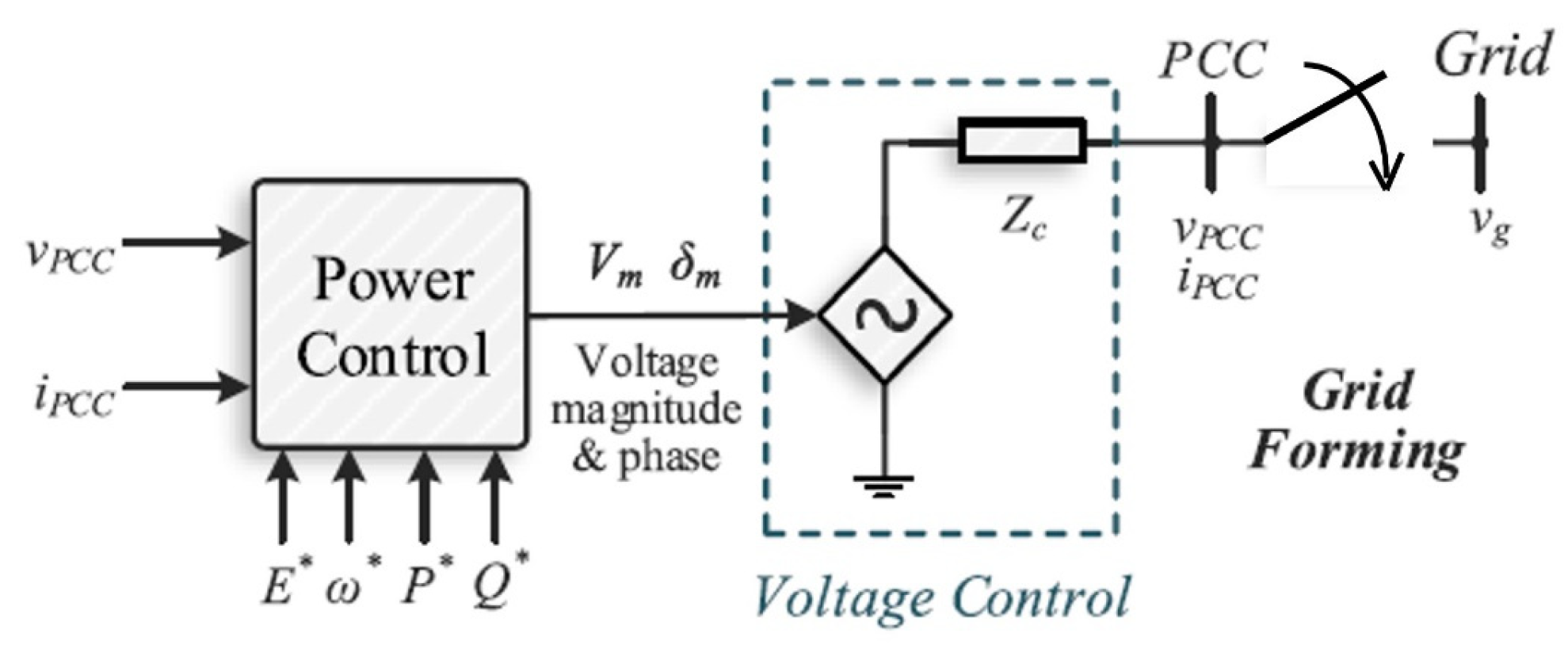
As mentioned previously, the grid-forming power converter appears as a low-output impedance connected to an ideal ac voltage source, where the voltage level and frequency
,
are set by utilizing an appropriate control loop, as indicated in
Figure 1. Therefore, the grid-forming converter needs an accurate system of synchronization in order to be able to work in parallel with other grid-forming converters. A real-world illustration of the grid-forming converter is the standby uninterruptible power supply (UPS), where it can form the grid voltage when a grid failure occurs. In the case of grid failure in a grid-connected microgrid system, the grid-forming converter will be employed as a reference if multiple grid-following converters are running on the system.
The following [
23] is a classification of certain grid-forming converter control strategies:
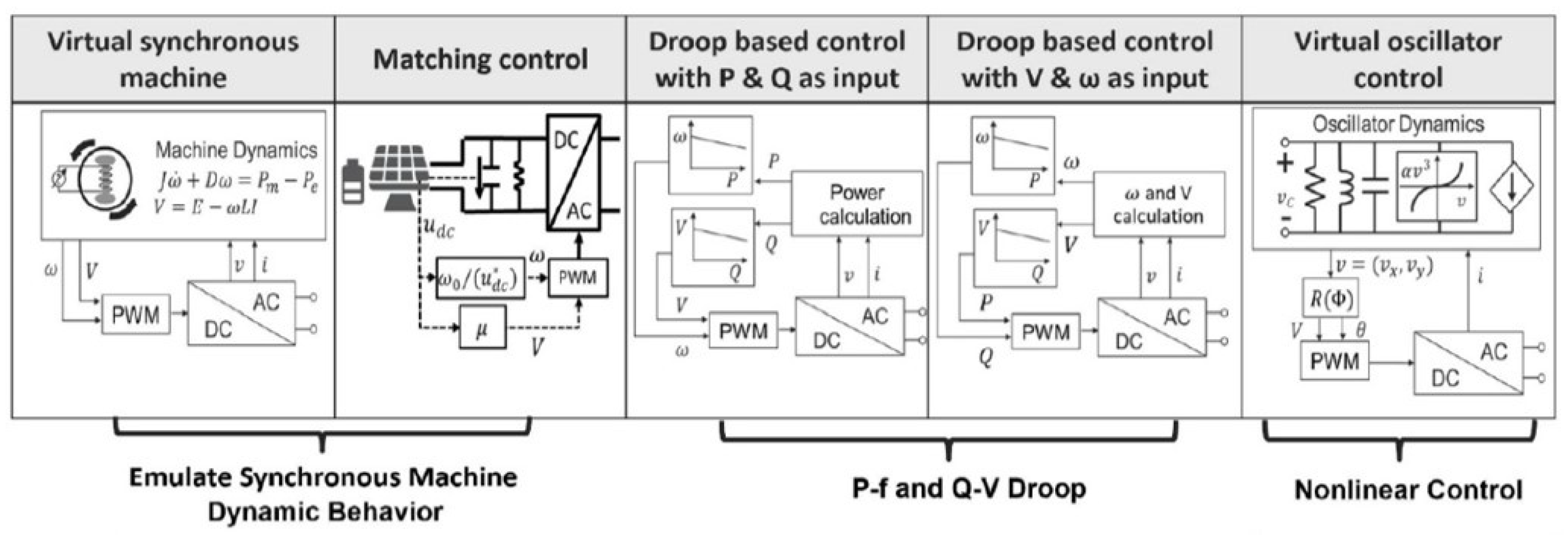
Droop control: this method offers a linear trade-off between the frequency and real power in addition to the voltage and reactive power. This principle is inspired from the steady-state operation of a typical synchronous machine. Therefore, the droop characteristics are expressed as and relationships. Thus, each distributed generation unit will have the same frequency and it will supply power according to its capacity or, in other words, its droop gain.
Virtual synchronous machines: this method employs the behavior of a synchronous machine in power systems to be applied in the inverter control. Here, the measurements of the inverter terminals are inserted as inputs into a digital model of a synchronous machine to deliver an inverter output according to the digital model. To match the machine characteristics, and , which are nominated as synchronverters, are usually employed. The virtual machine concept can be implemented considering the detailed electromechanical models or simply the simplified swing dynamics.
Virtual oscillator controllers: this method emulates the behavior of nonlinear loads where a digital model processes the real-time measurements like a virtual synchronous machine. The major difference is that an oscillator circuit with a natural frequency that matches with AC main grid frequency forms the digital model. Also, by tuning this oscillator circuit, the control bandwidth and nominal voltage can be adjusted. In steady-state conditions, this method will eventually offer and droops.
All the methods described above have analogous properties despite the differences between them. The inverter output of any of the abovementioned grid-forming controllers looks like a voltage source, with amplitude and frequency that changes with the power and load variation of the system. This hierarchy permits grid-forming inverters to instantaneously conform the load demand with the generated output power, control local voltage, and take part in frequency control without the need for a reference voltage from the main grid, as in the case of grid-following inverters [
24]. The control methods applied for the grid-forming inverters are depicted in
Figure 2. Here, the grid-forming inverter acts like a voltage source, which can be driven by one of the mentioned control methods. In the context of microgrids, grid-following and grid-forming inverters differ significantly in that the grid following always need a PLL as well as voltage reference to extract the real and reactive power.
3. System Structure and Methodology
As discussed earlier, the grid-forming inverter should be driven by a proper control methodology to deliver a reference voltage, as the main grid no longer exists. The reference voltage should be regulated by two cascaded voltage and current control loops before being sent to the grid-forming inverter.
Figure 3 depicts the structure of the implemented network, which includes one grid-forming inverter and one local load. The grid-forming inverter is represented by an ideal controlled voltage source. The reference voltage
is delivered to the inverter after being extracted and controlled by the droop control and sinewave generation as well as the voltage and current control loops, respectively. Those two blue subsystems will be clarified in the subsections that follow.
3.1. Droop Control and Sinewave Generation
In synchronous machines, the generator rotor speed is decreased if the demand of power is suddenly increased. Thus, the frequency is lowered in order to deliver extra power. This consistency between
and
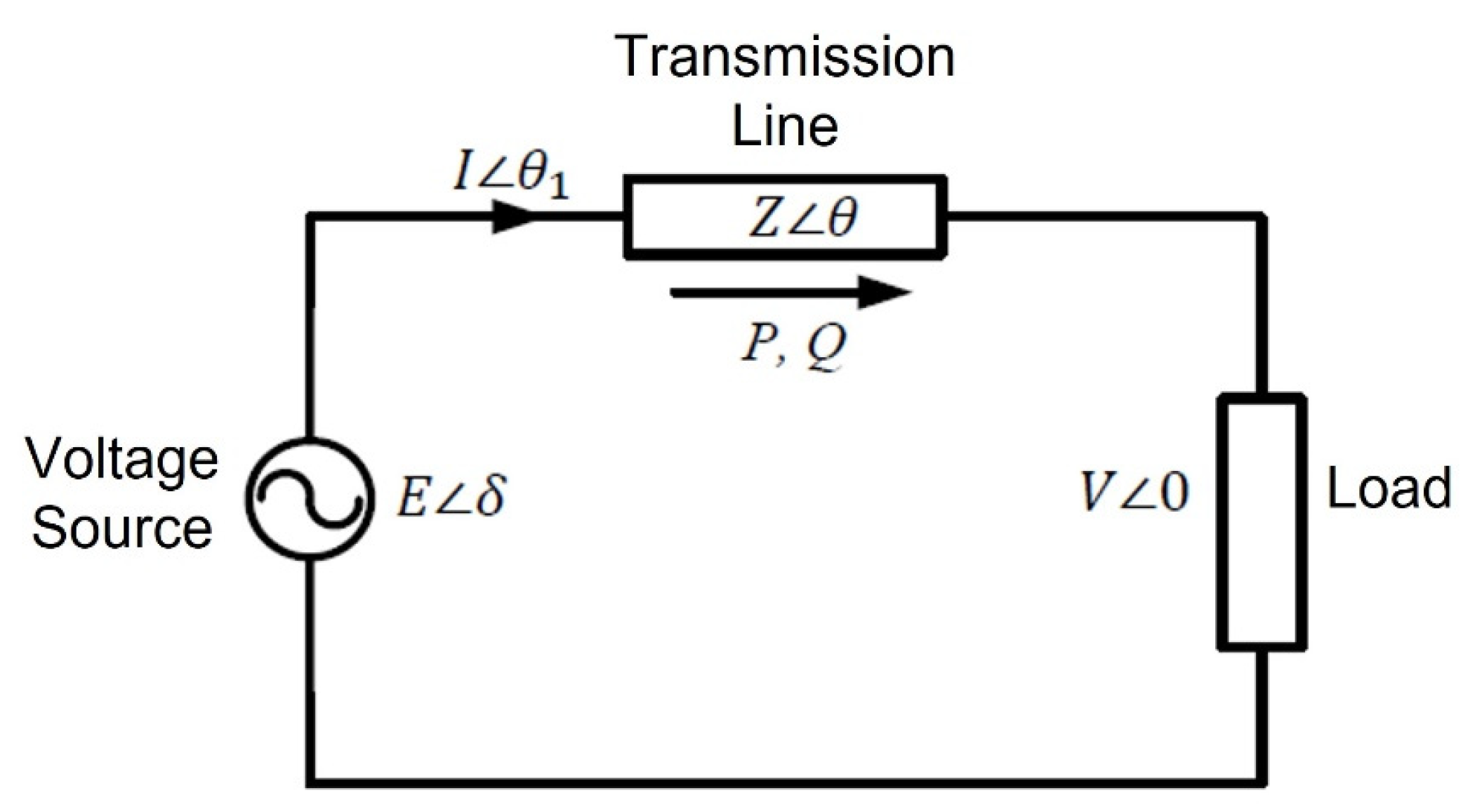
is introduced as a standalone control in DG systems. The only difference here is that the inverter lacks inertia, unlike the synchronous machine. As a result, the transmission-line impedance plays a major role in determining the droop-control-based active power and frequency
. Considering the system shown below in
Figure 4, which connects a voltage source with a load through a transmission line, the real and reactive powers are given as [
25]:
When
for an inductive transmission line, the power equations reduce to:
If the phase angle
is small,
and further reduction to the power equation yields
Thus, it can be observed that if the transmission line is inductive, the active power is connected to the phase angle, and the reactive power is coupled to the terminal voltage. However, the frequency is selected in place of the phase angle to regulate the active power for control of DG-based power converters. This is because the initial phase values of the DG systems are unknown in the absence of the grid. According to this logic, the
droop can be represented as:
Also, the terminal voltage and reactive power
droop are characterized by:
where
and
are the reference active and reactive power,
and
are the measured active and reactive power,
and
are the reference frequency and voltage, and
and
are the droop gain coefficients.
It is worth mentioning that as the droop gain coefficient is low, the control response will be slow, whereas for large droop gain coefficient, the load sharing becomes faster. This is due to the swap between the droop gain coefficient and stability of the system.
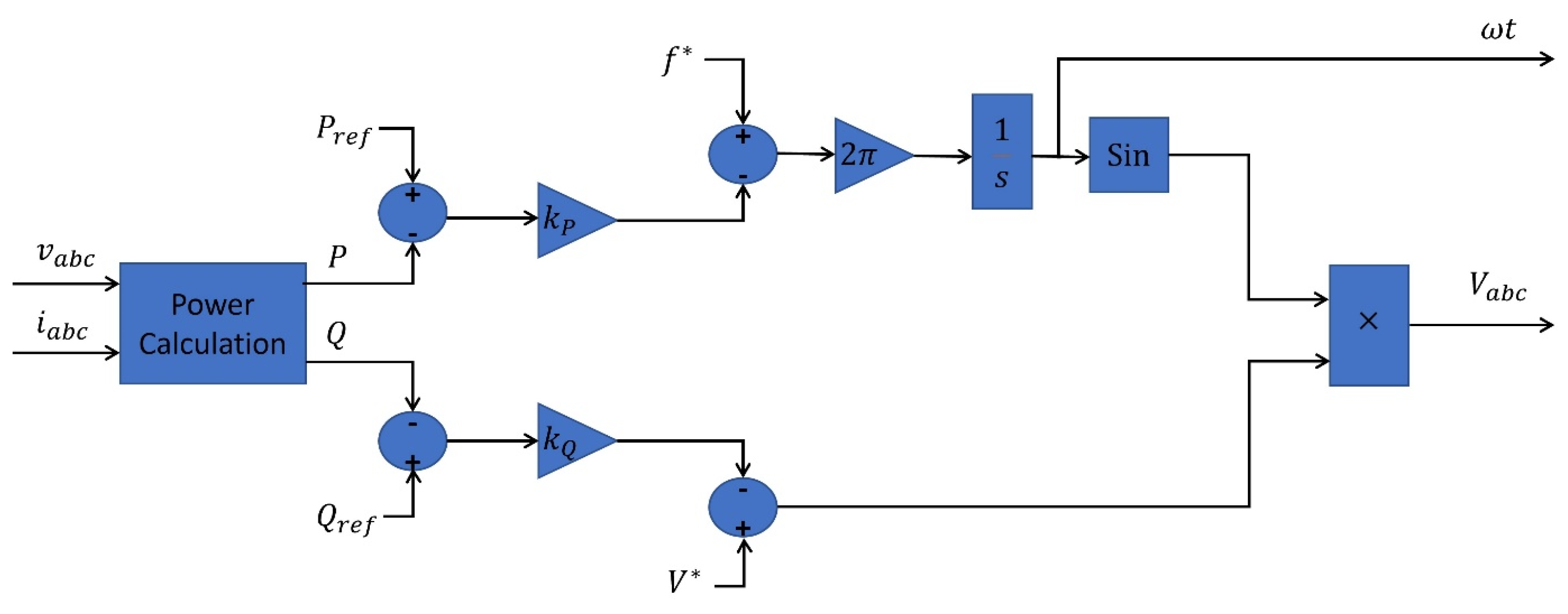
The concept resulting from Equations (5) and (6) has been implemented in the droop control and sinewave generation block depicted in
Figure 3. Its representation is presented, as shown in
Figure 5. Here, the measured current and voltage at the grid-forming inverter are inserted into a block that calculates the power to extract the measured real and reactive powers, which are then compared with their rated (reference) values.
The droop gain coefficients and are adjusted according to the capacity of the renewable energy source, in other words, the rated values for both active and reactive power of and . The output of these droop gains is compared with the nominal frequency and terminal voltage values. Thus, if the measured active power is increased/decreased, the frequency will be lowered/raised, respectively. This logic also extends to the measured reactive power and the terminal voltage. That is why the and droops have inverse characteristics. Finally, the voltage that should be controlled and the phase angle ωt required for transformation are extracted and inserted into the control loop block of voltage and current, which will be discussed further.
3.2. Voltage and Current Control Loops
In this section, the sinewave-generated voltage
from the droop control block will be regulated by two cascaded control loops, as depicted in
Figure 6. The control loop of voltage is in charge of controlling the output voltage, where the distinction between the measured and reference voltage is an input to the control loop of current that delivers the current reference to be injected by the converter. Only when the DG is operating in islanded mode and separated from the main grid does the voltage control loop exist. The current control loop regulates the current provided by the power inverter and tracks, at the same time, the current reference supplied by voltage control loop.
In the block diagram shown below, the ABC sinusoidal voltage is transformed into a synchronous frame by Park’s transformation to extract
and
, such that,
The measured and reference
voltages are then compared and passed through PI controllers to deliver the reference
currents. This part specifically identifies the voltage control loop. Further, the measured and reference
currents are compared and also inserted to PI controllers to deliver the final voltage reference of the grid-forming converter, which includes the reference voltages
and
. This part specifically identifies the current control loop. The voltages
and
are transformed into stationary reference frame by the inverse Park’s transformation, such that,
In real practice, the grid-forming converter is fed by a balanced dc source driven by a fuel cell or a battery, for example. This dc source remains disconnected when the system is operating within acceptable limits, and it is connected in case of grid failure to form the grid voltage and frequency.
A flowchart of the overall control process for generating the reference voltage of the grid-forming converter is depicted in
Figure 7. In the flowchart, the droop characteristics are adjusted to deliver the sinusoidal signal; then, it is passed through voltage and current control loops to generate the reference voltage.
4. Discussion of Simulation Results
4.1. Setting the Droop Characteristics
The grid-forming power converter’s droop characteristics have been tuned so that the voltage
controls the reactive power
and the frequency
controls the active power
. The
and
settings are presented in
Figure 8a,b. The permissible limits of the frequency and RMS voltage in the distribution networks are
and
, respectively. The frequency range in the
droop has been adjusted between
as the active power is assumed to be generated to satisfy the load and not to be stored for future usage. Keep in mind that if the active power needs to be stored, the frequency range should be from
. In addition, the voltage range in the
droop has been adjusted between
as the reactive power is assumed to be inductive (load draws + ve VAR). If the reactive power is capacitive, the voltage range should be from
. The real and reactive power range in the
and
droops was adjusted arbitrarily, as there is no restriction similar to the permitted ranges for voltage and frequency.
In subfigures (a) and (b), the droop gains
and
are calculated as follows:
Those droop gains are inserted into the unit of control for the grid-forming power converter, where, if the active power of the load is increased, the frequency is decreased and vice versa. Furthermore, if the load reactive power is increased, the voltage is decreased and vice versa. The references of active and reactive power and are and , which represent the maximum capacity of the grid-forming inverter, whereas the frequency and voltage references are and are and , respectively.
4.2. Performance Evaluation under Load Variation
The proposed model structure of
Figure 3 was constructed in Matlab/Simulink version R2014b, where the grid-forming power converter was designed as a controlled voltage source. The load is assumed to be a resistive-inductive
load to examine the reaction of the proposed droop controllers, and the line is an
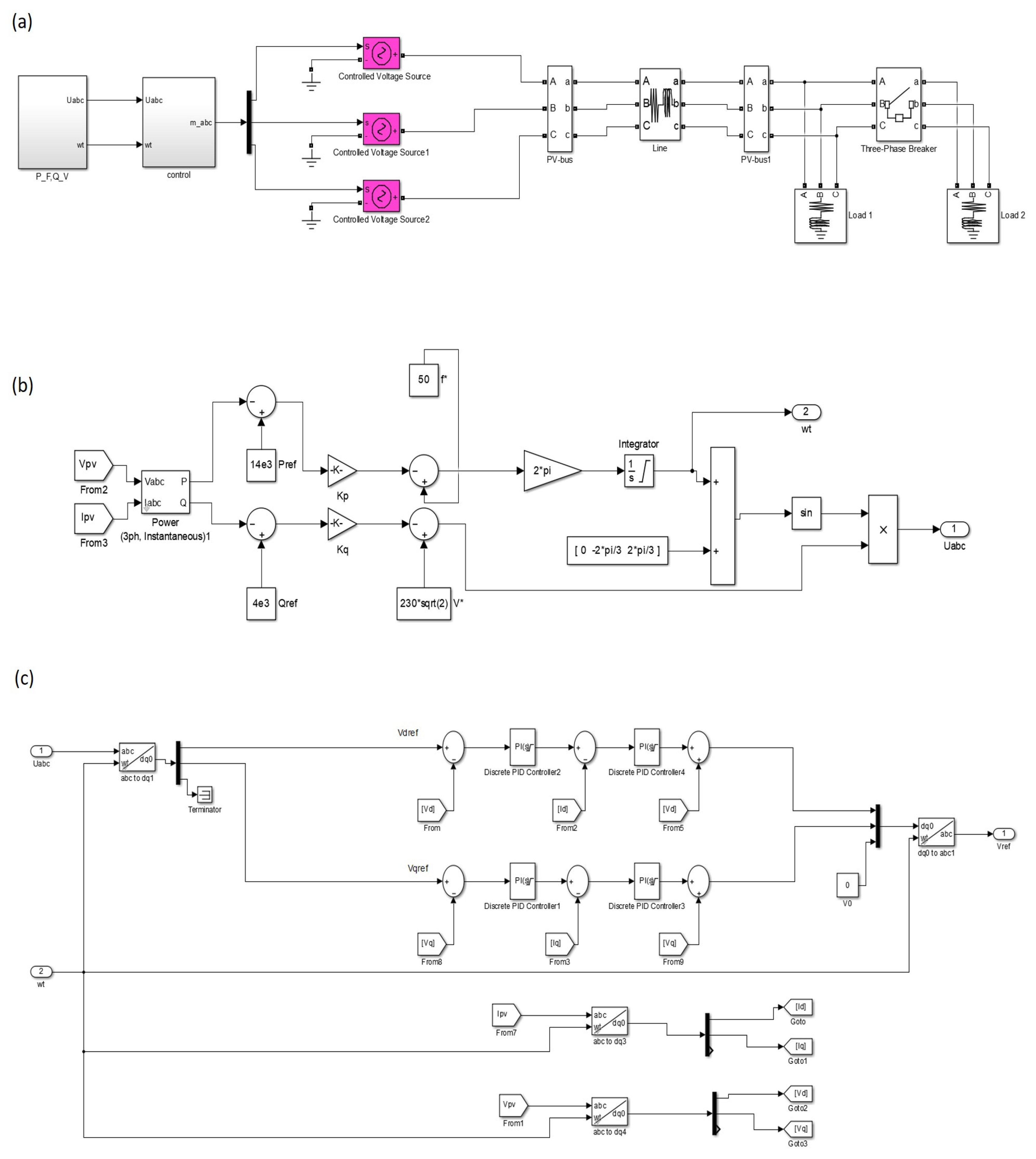
series branch. The Simulink model of the proposed network, including the droop and control structure, is presented in
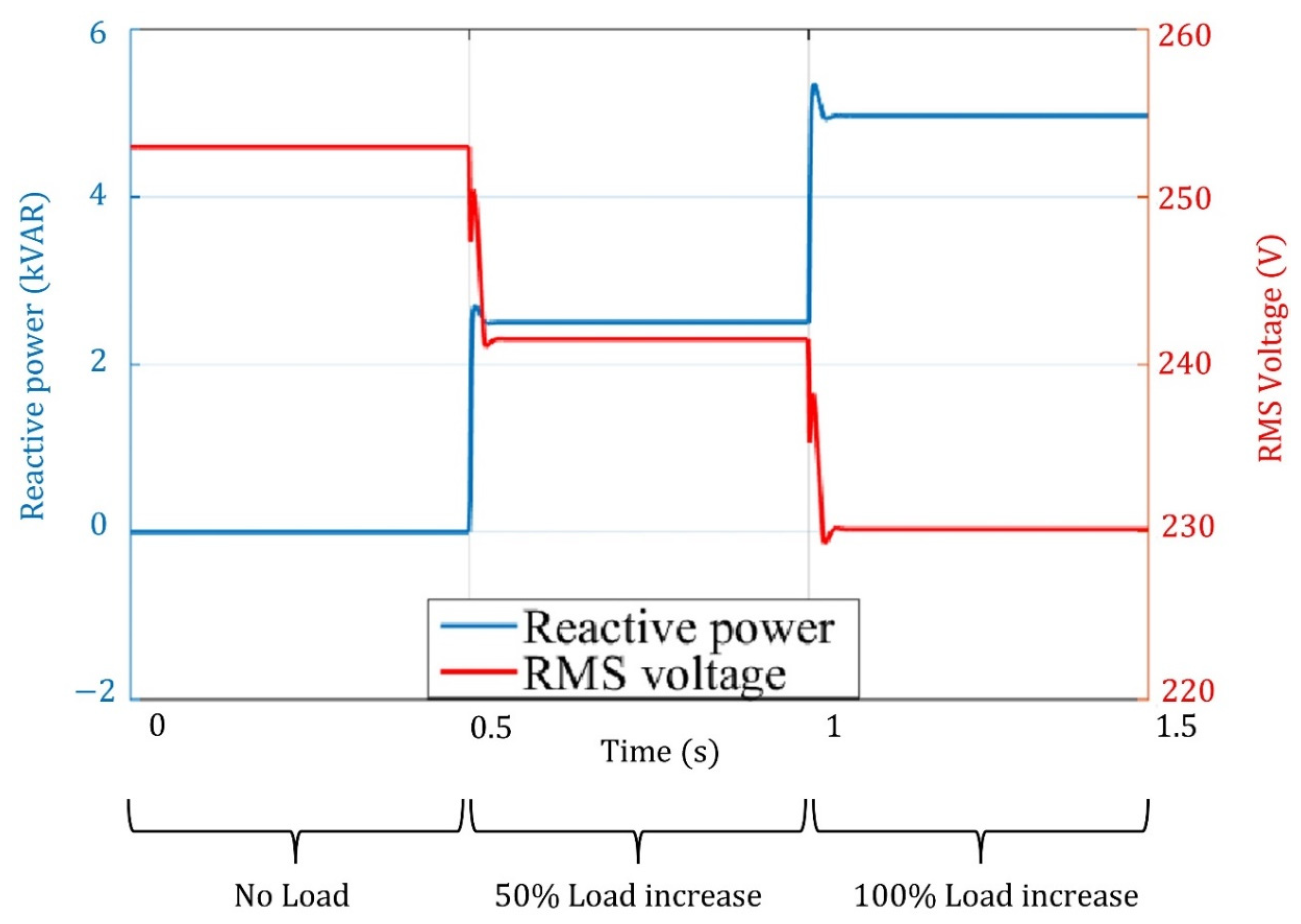
Figure 9. Subfigure (a) shows the network model, while subfigures (b) and (c) present the droop and sinewave generation in addition to the voltage and current control loops. The evaluation of the results was divided into three regions: the first region between
is when no load is connected to the grid-forming inverter, the second region between
is when the load is increased to
of the grid-forming inverter capacity, and the third region between
is when the load is increased to
of the grid-forming inverter capacity. Reactive power vs. voltage
droop and active power versus frequency
droop performance under the load variation for the three regions are depicted in
Figure 10 and
Figure 11. The left
y-axis for the two figures represents the active and reactive power, and the right
y-axis represents the frequency and RMS voltage, respectively.
In no-load conditions (the load active and reactive power are zeros), the grid-forming inverter ran at the highest frequency, , which corresponds to zero active power according to the assumed droop setting. The same condition was applied for the reactive power where the RMS voltage was at the highest permissible value, , corresponding to the assumed droop setting.
When the load is increased to of the grid-forming-inverter capacity, the frequency is decreased to according to the assumed droop so that the inverter active power is increased to to satisfy the active power load demand. Similarly, the RMS voltage is decreased to according to the assumed droop so that the inverter reactive power is increased to to satisfy the reactive power load demand.
Furthermore, when the load is increased to of the grid-forming inverter capacity, the frequency is decreased to (lowest frequency permissible value) according to the assumed droop so that the inverter active power is increased to (maximum capacity) to satisfy the active power load demand. At the same time, the RMS voltage is decreased to (lowest RMS voltage permissible value) according to the assumed droop so that the inverter reactive power is increased to (maximum capacity) to satisfy the reactive power load demand. It should be noted that the spike in the RMS voltage is due to the PI controller reaction in the control loop at the moment of 50% and 100% load increase. When the PI controller is subjected to a sudden load increase, it needs a little bit of time to minimize the error difference between the measured and reference quantity. That is why a spike appeared and then settled down to a steady-state response.
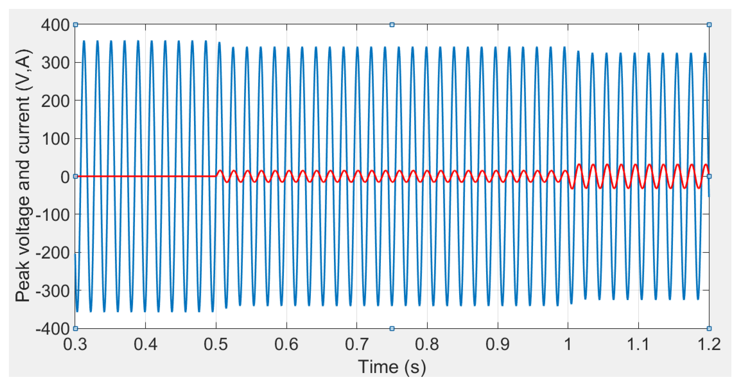
The peak voltage and current at the grid-forming inverter bus during the load variation condition are depicted in
Figure 12. It can be seen that the current is zero until
s as an indication of the zero-load demand while the voltage is oscillating at
times 253 V. During
, the current increases as the load demand is increased to 50% of the inverter capacity while the voltage is decreased to
times 241.5 V due to the reaction of the
droop to satisfy the reactive power demand of the load. After
, the current increases further due to the further increase in the load demand. Thus, the inverter needs to generate more active power according to the
droop to satisfy the active power load demand. Also, the voltage is decreased to
times 230 V due to the reaction of the
droop to satisfy the further increase in the load reactive power demand.
4.3. Validation of Results
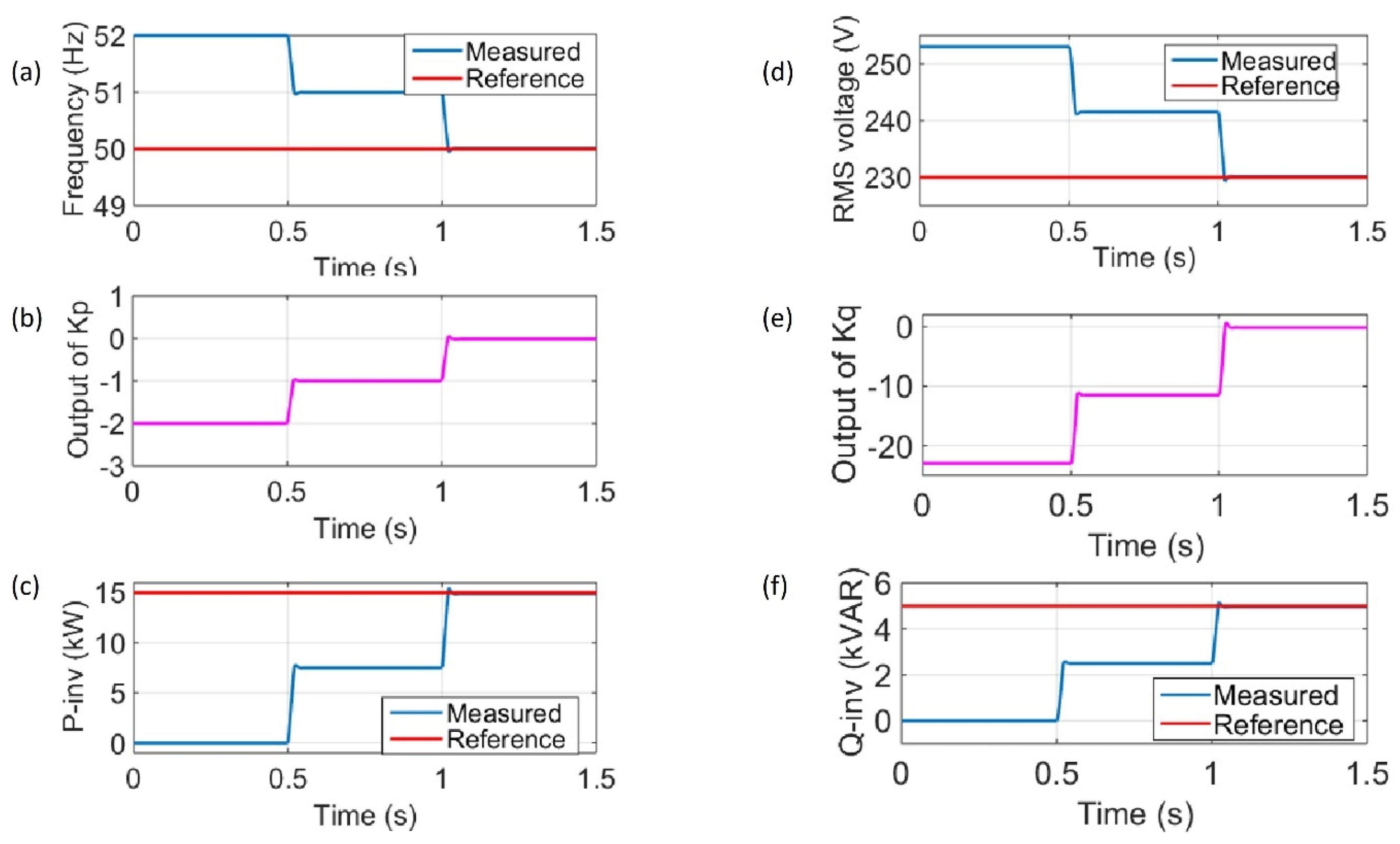
The validation of results is accomplished by monitoring the reference and measured quantities of the droop control loop of the grid-forming inverter, as presented in
Figure 13. As shown from subfigure (a), the reference frequency
is always
, and the measured frequency is changing according to the load demand variation and depending on the assumed
droop setting. Notice that the output of
in subfigure (b) is changing exactly according to the difference between the measured and reference frequency. Extending the same logic for subfigure (c), the grid-forming inverter active power is changing according to the change in
, which represents the assumed
droop characteristic.
In subfigure (d), the reference voltage is always , and the measured voltage is changing according to the load demand variation and depending on the assumed droop setting. Notice that the output of in subfigure (e) is changing exactly according to the difference between the measured and reference voltage. Extending the same logic for subfigure (f), the grid-forming inverter reactive power is changing according to the change , which represents the assumed droop characteristic.
Furthermore, to confirm that the assumed droop control discussed in
Section 4.1 has been applied efficiently in the control of the proposed grid-forming inverter, the measured active power and frequency values in addition to the measured reactive power and rms voltage values are plotted as presented in
Figure 14. Notice that the resultant
droop equals exactly the assumed
droop, in which
and the resultant
droop equals exactly the assumed
droop, in which
.
4.4. Active and Reactive Power Sharing
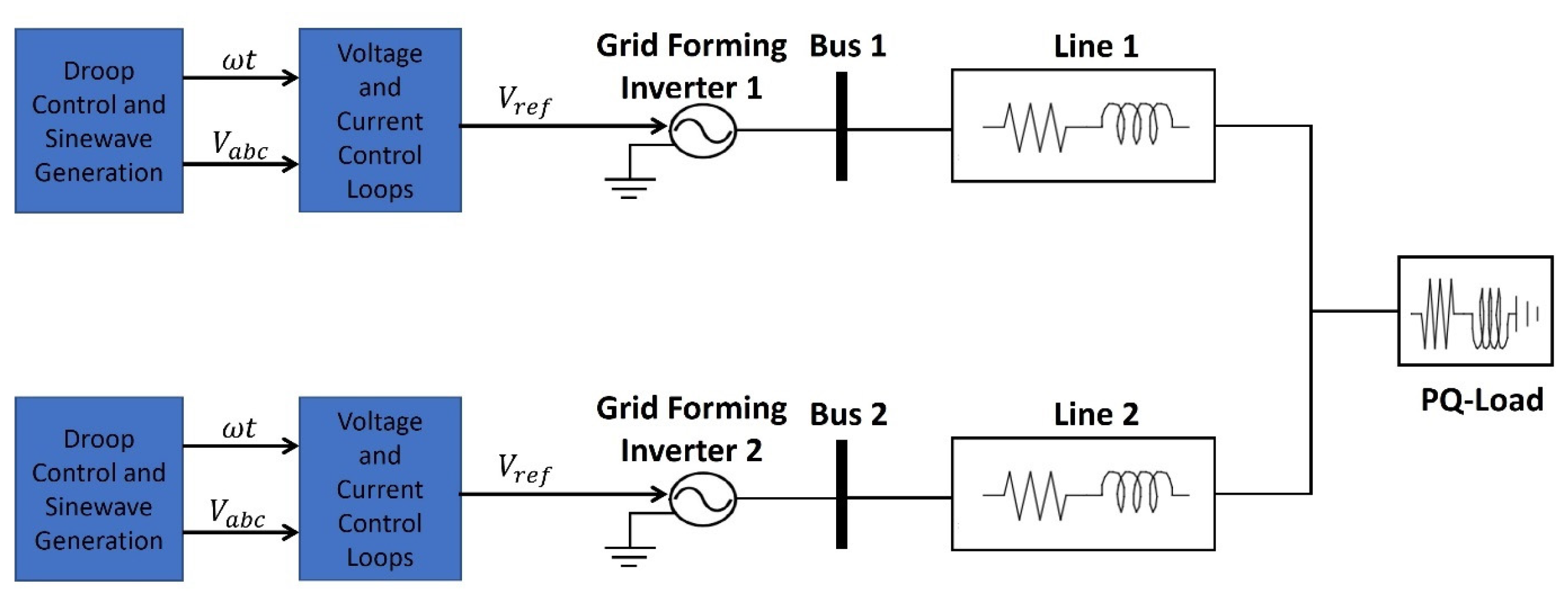
Sharing between active and reactive power among the grid-forming inverters based on their rated capacity is employed to avoid overloading the sources. A microgrid consisting of two grid-forming inverters sharing a single load is represented in
Figure 15 to investigate how the droop controllers equally shared the load demand of active and reactive power.
The droop characteristics of both grid-forming inverters are adjusted to be identical so that they share the same amount of the load demand in terms of real and reactive power. Their settings are as follows:
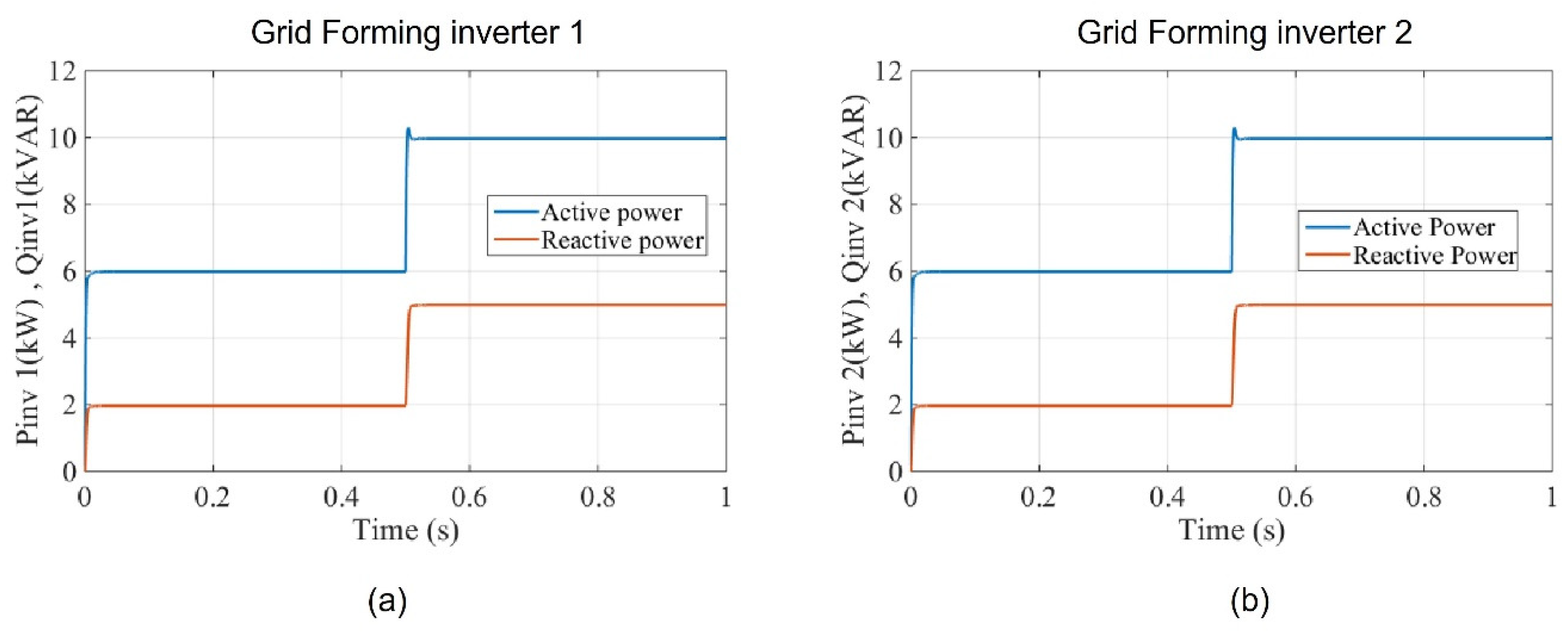
The single load in the above model is assumed again as PQ load, where between , the demand of active power is and the demand of reactive power is . After that the load demand is increased between , the demand of active power becomes and the demand of reactive power becomes .
Figure 16 shows the power sharing in terms of both real and reactive power for both inverters that are grid forming. It can be noticed how both inverters share the same amount of active power and reactive power during the normal load period and when the load is increased. This is due to the fact that both inverters are equipped with the same droop characteristics.
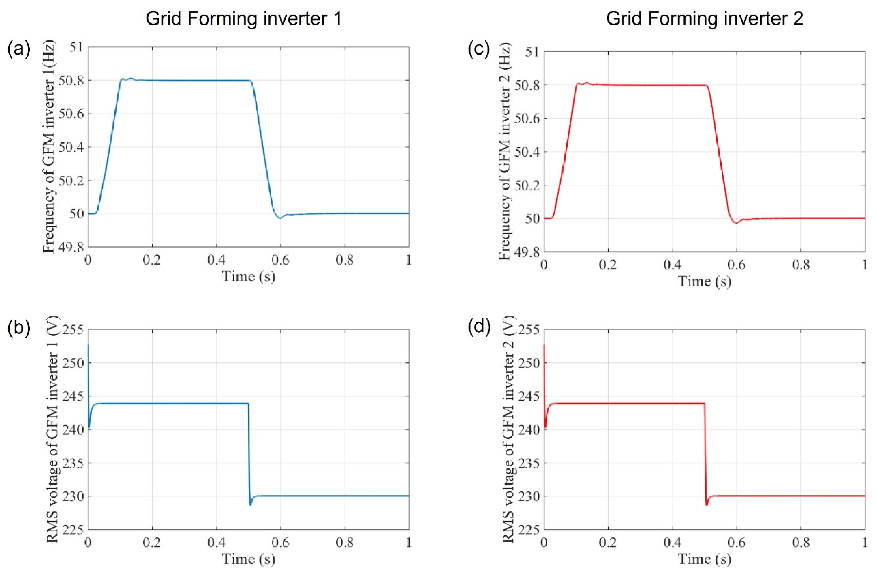
The frequency and RMS voltage for both grid-forming inverters are presented in
Figure 17, where it can be observed that the change in frequency and RMS voltage is the same for both inverters.
Here, the frequency for both inverters was oscillating at when the total load demand of active power was and then dropped to as the active power load demand increased to , which is divided between the maximum capacity of both grid-forming inverters ( for both). The same was the case for the RMS voltage, where the voltage of both inverters was oscillating at approximately when the total load demand of reactive power was and then dropped to as the reactive power load demand increased to , which is divided between the maximum capacity of both grid-forming inverters for both.
5. Conclusions and Future Work
Inverters of the grid-forming type have been suggested as a favorable arrangement for the various problems in modern power systems. In this paper, the autonomous operation of the grid-forming inverter with the integration of the droop control as a decentralized method was investigated. The decentralized method used in this work confirms the applicability and accuracy of installing grid-forming inverters in the distribution network without the need for communication. The simulation results confirmed the precision of the assumed droop setting with the resultant droop in response to the PQ load variation in the three regions. It was also clear how the load demand is exactly satisfied with the generation that employs the droop control methodology. Furthermore, the simulation results confirmed the power sharing, where the generation of active and reactive power for both grid-forming inverters was divided equally to satisfy the load demand. Future work can include further investigations into grid-forming inverters connected at the distribution and transmission levels. These investigations can be the hardware implementation, energy storage, system protection, fault ride through capability, stability analysis, economic aspects and economic dispatching of units, and the transition from islanded mode to grid-connected mode. Another path for future work may include a comprehensive analysis of the limitations and constraints inherent in the proposed methodology and the overall study.
