Abstract
Recently, the increased adoption of electric vehicles (EVs) has significantly demanded new energy storage systems (ESS) technologies. In this way, Lithium-ion batteries (LIB) are the mainstream technology for this application. Lithium presents several advantages compared with other chemicals because it can provide delivery energy for a long time, a long lifetime, and high density and capacity. The LIB comprises several cells connected in different configurations, such as parallel, series, or combinations. This variety of designs makes the monitoring control process more complex, complicating diagnosing and prognosis of abuses and failures. To observe these difficulties, this paper presents sixteen experiments of a mini-packing of four cells under the main abuses found in the LIB. The time series data were collected during the abuses and saved in a CSV file. The results indicated that the current, temperature, and voltage should be used to identify the external short-circuit (ESC) failures in the packing of batteries. On the other side, only the voltage signature is able to determine the Over-Charging (OC), and finally, the combination of temperature and voltage should be used to identify and locate the Over-Discharging (OD) failures in different arrangements of packing. This study also provides ways to build mechanisms to protect the cells and avoid loss of performance and safety issues.
1. Introduction
The application of Electric Vehicles (EVs) has been growing significantly worldwide in the last few years. This growth happens for several reasons, such as local government tax breaks and credit lines, decreased battery costs, and the current appeal for fossil fuel consumption reduction [,].
This increase accelerated the demand for energy storage systems (ESS) for vehicles and trucks [,]. Lithium-ion batteries (LIBs) present several advantages compared to other proposals (such as lead acid batteries) [,,]. Therefore, this technology has been applied with different chemicals. LIBs present remarkable characteristics such as low self-discharging, long storage time, long lifetime, high density, and capacity, making this technology the state-of-art for ESS [,]. However, it is more sensible if compared with other chemicals. Thus, the operation of this battery must be controlled, respecting maximum thresholds of current, temperature, and voltage to reduce the chances of performance and safety issues and prolong the device’s lifetime [].
In this way, the operation of LIBs requires a battery management system (BMS). This device controls the heart of the battery and monitors and controls the entire operation of the battery according to the demand of the vehicle. Generally, BMS processes several tasks simultaneously: monitoring, equalizing, and control [,]. By monitoring, the device observes online the main parameters of the cells, such as voltage, current, and temperature. These parameters are helpful for the equalizing process and the control [,,].
The equalizing process demands maintaining the energy level of the cells in similar behavior during the charging and discharging steps. In this scenario, it is possible to find two different methods: passive and active. The passive process removes the energy of the cells with the higher energy level to maintain every cell at the same voltage level by using passive elements such as resistors. On the other side, active equalizers transfer energy from cell to cell by active elements such as capacitors and inductors. This process reuses the energy and reduces energy elimination [,].
Moreover, some BMS present thermal control and failures to diagnose. This process depends on the data collection to operate and maintain the battery in safe conditions. The efficacy of this control depends on several characteristics, such as fault sensors, cell connection faults, and others []. In addition to that, the complete packing of the battery is composed of several cells connected in different configurations (string, parallel, or a combination of both), which makes the control more complex. In the case of inaccurate measurement, issues can appear in the BMS control, especially in finding and locating failures in the cells, state of charge (SOC), and state of health (SOH) estimations [,,].
Additionally, the cells’ manufacturing process and own characteristics, such as impedance, density, and others, result in packing containing cells with different features. Consequently, the packing produces imbalanced cells and different degradation rates []. These unbalancing cells may force the BMS to work on the cells with the lowest voltage level threshold, making the process inefficient and sensible to failures [,].
This scenario happens especially in configurations where string arrangements are found. In this situation, the cells’ voltage and temperature are usually monitored, but there is only one current sensor at the entry or exit of the packing. In addition to that, the behavior and signature of the different types in LIB are very similar. This similarity makes it difficult the diagnostic faults in LIB packing [].
This work presents a collection of experiments carried out in a packing of LIB composed of four cells with different configurations. First, a BMS has been built based on Arduino Mega to collect the main parameter of the cells (temperature, voltage, and current) and send it to Edge Computing by serial connection, in which the data were stored in CSV files. Then, several experiments with external short-circuit (ESC), Over-Charging (OC), and Over-Discharging (OD) for different arrangements were performed. The main contribution of this paper is the analysis of the collected data and the indications of insights into the construction of failure mechanisms.
2. State-of-the-Art
The arrangement of a LIB can be segmented into three parts: cell, module, and packing. The cell part is the minor component of the packing. After that, the module comprises several cells connected in a series or parallel. Finally, packing is composed of several modules. This connection can be in a string arrangement, a similar arrangement, or even a combination of both, depending on the current and voltage demanded by the electrical motor [,].
Despite that, the different configurations tend to increase the complexity of the BMS operation. For example, only one current sensor is observed in a stack module. In a regular function, the current in a string configuration is the same for every cell []. Nevertheless, in the case of a failure (for example, an external short-circuit (ESC)), more sensors could help the BMS to identify the abuse and the location.
In the literature, it is possible to find several approaches that mitigated this problem by developing mechanisms and controls. Zheng et al. [] developed a hybrid model with an unscented particle filter to identify fault sensors of voltage and current sensors. In the same direction, Kang et al. [] proposed an online mechanism to identify cell failures in packing by observing the correlation coefficient of the sum of two nearly cells and one connection. This method could reduce the main difficulty of the similar behavior of the cells, sensor faults, and problems in the connection between the cells. The authors described that the mechanism could identify the fault cells by correlating the neighbor’s energy.
Yang et al. [] presented a mechanism based on the Kalman Filter to diagnose on board the soft short-circuits in Lithium-ion packing. Xu et al. [] used a proportional integral observer to analyze and identify fault failure in the current sensor. The author describes the importance of the current sensor for estimating energy (SOE). The method could reduce the error of SOE to a value lesser than 2%.
Li and Wang [] introduced a method to detect a fault in the correlation coefficient based on voltage measurement. Xia and Mi et al. [] described a strategy based on the total voltage monitored of a packing of cells in a series configuration. According to the authors, this proposal reduces the number of sensors. In addition to that, the authors presented an interpretation matrix to differentiate the cells with faults from those with sensor faults. On the other hand, Hong et al. [] presented a study using Shannon entropy to predict the time and location of thermal failures in battery packs with big data.
Some other works presented other mechanisms, such as Xu et al. [] with several protection mechanisms, including mechanical and electrical, to prevent failures in LIB and Cai et al. [], who proposed the detection of ISC failures in large packs of batteries with CO2 gases. Finally, Wang et al. [] presented an application of a neural network to detect failures in packs of batteries.
The reduction of available current sensors raises the chance of abuses in LIB. These abuses can be classified into mechanical, electrical, and thermal.
2.1. Mechanical Failures
Mechanical abuses can be found in batteries with assembly problems, high vibration levels, or even water immersion. These situations can cause the ESC and cause issues in the LIB regarding capacity fade and even risks of accidents [].
An ESC provokes the flow of a high current from the cathode to the anode and significantly increases the internal temperature of the cell. This abuse causes rapid self-discharging in the cell [,].
Some batteries have mandatory internal protections to avoid accidents in the battery. For 18,650 standard cells, current interrupt device (CID) and top vent are mandatory mechanical mechanisms that protect the cell during failures. CID comprises a flexible membrane named the top disk that can move upwards in case of high pressure in the cell caused by ESC, for example. This irreversible mechanism can avoid critical consequences such as a thermal runaway (TR). In addition to that, these cells have a top vent used to eliminate the internal gases of the cell []. In case of failed operation of the protection mechanisms or even in their absence, the ESC can cause electrical and thermal failures.
2.2. Electrical Failures
In electrical failures, it is possible to find internal short-circuit (ISC), Overcharging (OC), and Over-discharging (OD). An ESC can provoke an ISC, overheating, and, consequently, an TR. The ISC happens when there is direct contact between the internal positive and negative elements. This abuse happens slowly at the beginning and causes several issues in the cell during its progress. This process significantly increases the internal temperature and can drive a TR []. This failure is irreversible, and the cell is discarded when it happens.
OC occurs when the cell charges at a high current and its voltage level are above the safety threshold. It increases the internal temperature and causes an ISC, overheating, and a TR []. OC speed-up the oxidation process and difficult the intercalation of the ions in the graphite layers. This effect accelerates the transformation of the Lithium-ions into metallic form. In this way, the resistance increases, reducing the cell’s capacity [].
Conversely, OD is observed when the cell is discharged at a voltage level below the safe threshold at a high current. The OD’s criticality depends on the energy depth that the cell reaches []. This abuse speed-up the cooper dissolution and increases the accumulation of lithium on the cathode []. OD can also cause ISC. However, this consequence happens slower than those caused by OC [,].
2.3. Thermal Failures
The thermal failures are classified into overheating and TR. The first is verified when the temperature is high. The threshold depends on the chemical and the type of cell. If the overheating is not controlled, a TR can appear. This failure rapidly increases the cell’s temperature, causes irreversible complications in the battery, and can even cause fire and other accidents [].
TR can nearly destroy the cell and contaminate the others by transferring the heat with direct contact or connectors [,]. It is essential to use mechanisms to identify the abuse previously, find the location and isolate the problematic cell to guarantee the safety of the packing and the vehicle.
3. Proposed Method
A mini-packing with four cells with different configurations has been built to introduce our proposal, as observed in Figure 1. In Figure 1A, the experiments were conducted with packing in a series configuration. In contrast, Figure 1B indicates a packing composed of two modules in a series, each with two cells in parallel.
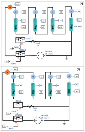
Figure 1.
Configuration of the experiment setup: (A) Pack of four cells in series; (B) Pack of two stacks in series.
An Arduino Mega is used as BMS. In this case, BMS was used only to monitor the cells during the experiments. This way, during the investigations, BMS collected the main data from the four cells every second. Four NTC10K sensors were used to measure the temperature on the surface of the cells. The temperature sensor has been fixed on the cell’s surface near the cathode side. The output of the sensors was a voltage ranging between 0–5 V. A resistor divisor converts the analog to a digital signal collected individually by the analog channel from Arduino A8, A9, A10, and A11.
The voltage of each cell is measured by a resistor divisor and connected to the analog channel of BMS A4, A5, A6, and A7. Finally, the current signal is measured in different positions. According to Figure 1A, there is a single current sensor for each cell, and the extra current sensor C0 is considered from the actual sensor, while the C1, C2, C3, and C4 are the virtual sensors because they would not appear in a real case. Similarly, for the Figure 1) configuration, there is also an extra sensor named C0 that collects the current signature of the packing in the entry battery.
Every current signature is measured by a hall effect sensor ACS712 5 A, which delivers an analog signal between 0 to 5 V in the analog channel A0, A1, A2, and A3, and the extra sensor C0 delivers the sign to A12. Arduino Mega collects and sends the data to the Raspberry Pi, which works as Edge Computing and stores the data in a CSV. The Arduino and the Raspberry communication is performed by serial connection and protocol.
According to Figure 1, IRF9640 channel P operates the charging, and IRF44z channel N discharging. A PWM signal is sent by the Digital 5 to control the discharging current (the circuit is named discharging regulator (DR)). The charging regulator (CR) is controlled by Digital 6 to open or close the IRF44Z to maintain the current constant during the charging process. An external source of 30 V/5 A was used to charge the cells.
Considering these devices and the circuit, sixteen experiments have been carried out with cells 18,650 with a capacity of 1700 mAh and nominal voltage equal to 3.7 V (see Table 1). The OC, OD, and ESC experiments were performed with six different packing configurations, according to Figure 2.

Table 1.
Specifications of the Lithium-ion ICR18650-22P battery used in the experiments.
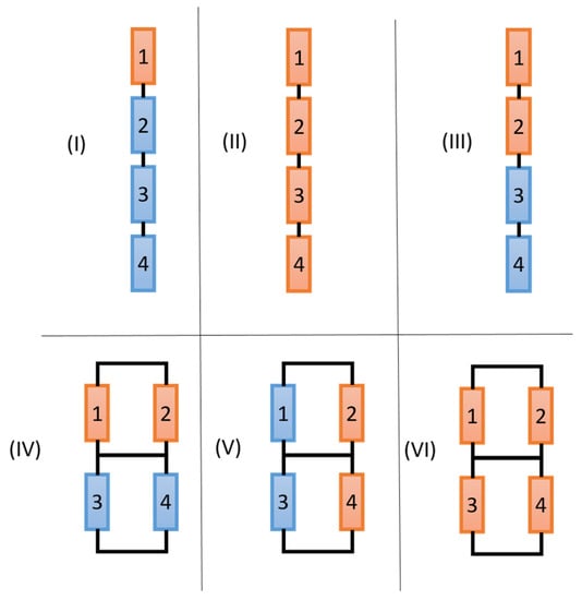
Figure 2.
Six different configurations of packing and failures were applied. The blue cells are under normal operation, and the orange cells are under abusive operation.
Table 2 presents the experiments, detailing the types of tests. All experiments are related to the charging and discharging process. The experiments in the charging process were performed at a constant current equal to 1100 mA (0.5 C). The others regarding the discharging cycle have been carried out with a continuous current similar to 1100 mA (0.5 C). The experiments were conducted in a controlled room between 24 °C and 26 °C.
Table 2.
Description of the experiments: sixteen experiments, six configurations, and four types of abuses.
Each ESC abuse took 30 s with a low resistance equal to 150 mΩ and was conducted automatically by a relay operated by a created routine running in the Arduino Mega. The direct contact (with low resistance for the current) forces the high current to flow from cathode to anode, considerably raising the internal temperature and pressure of the cell.
On the other hand, the OD abuse took time until the voltage was below or equal to 2.5 V. The time for OD in these experiments depends on several characteristics such as voltage level, arrangement, and position of the cells to come to the OD abuse. The pack was discharged at a constant current equal to 0.5 C during discharging. Once the first cell entered the OD range, each experiment took more than two minutes, and the investigation ended.
The OC abuse was conducted during the charging process at 0.5 C. When the voltage of the first cell was registered above the upper limit (4.25 V), the system experimented for more than three minutes before the end. The data collected during the experiments are saved in CSV files. Then, they are uploaded to the Anaconda Environment to be analyzed graphically with Pandas and Matplotlib tools.
The following section describes the analysis and the discussions of the results.
4. Discussion
As already discussed in item 3, Figure 1 indicates the presence of one current sensor for each cell. Despite that, there are limited sensors in the packing, particularly when the packing has a string arrangement in a real case. This work considers C1 for series arrangement and C0 for parallel configuration as the primary current sensors. The other is considered as virtual measurements. On the other hand, the temperature and voltage have been measured for each individual cell because it reflects reality. In addition to that, a reference sensor has been inserted in the data to demonstrate how the signal should be in case of non-failure found in the packing.
This investigation demonstrates how difficult it is to identify abuses in the packing of LIB. This section shows the data analysis of the sixteen conducted experiments. The results are segmented into three types of abuses: ESC, OC, and OD.
4.1. Analyzes of ESC
This subsection shows how to find ESC abuses in packing LIB for several configurations. First, two experiments have been performed for configuration (I): one during the charging process at 1.1 A and the other under the discharging process at 1.1 A (see Figure 2). The behavior of the main parameters during the charging process is observed in Figure 3.
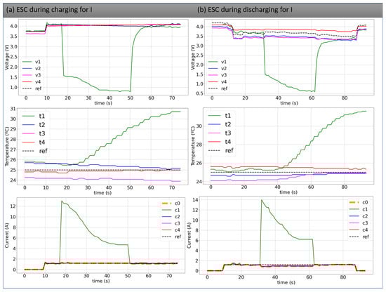
Figure 3.
Behavior of the main parameters of the four cells in series during an ESC in cell #1.
Figure 3a shows the voltage of cell #1, suffering a local ESC for 30 s. During the abuse, the voltage of this cell decayed to close to 1 V, while other cells maintained a voltage close to 4.2 V. The reference voltage also remains close to 4.2 V in the case of non-failure. The temperature of cell #1 increased significantly during the experiment due to the high current discharging the cell with low external resistance and came to close to 30 °C at the end of the ESC. The other cells maintain their temperature constant at about 25 °C (as the reference).
According to Figure 3a, at the beginning of the ESC, the current C1 rises from 1100 mA to almost 14,000 mA but decays until 6000 mA at the end of the process. Sensors C0, C2, C3, and C4 measured the charging current of 1100 mA according to an external source. In the case of a normal operation, the reference current should be similar as observed by C0, C2, C3, and C4 because the external source forces the current to migrate with the same magnitude.
Assuming that only C0 is present in a real case of string arrangement and there is a single ESC abuse in the packing, C0 could neither identify an ESC in the packing nor indicate the location and the cause. Then, the abuse can be found by monitoring the voltage and the temperature of the cell.
In addition, the curves of an experiment of an ESC in a single cell during the discharging process are observed in Figure 3b. The ESC in cell #1 reduces the availability of energy to be used for the load during the abuse. Then, only cells #2, #3, and #4 feed the load. Therefore, the current (C0, C2, C3, and C4) suffers a small fall due to the reduction of availability energy compared to the reference. However, DR control maintains the current constant to feed the load resistance. In addition to that, C1 registered a similar signature of the current in cell #1.
Moreover, the temperature increased significantly in cell #1, and the voltage decreased below 0V. As in the ESC during charging, the temperature and voltage of the cell are the parameters to detect a failure and the location of the abuse.
The ESC for configuration II (according to Table 1) is also performed during the charging and discharging process. Figure 4a shows the parameters measured during the charging. In this experiment, a complete ESC is performed between the positive pole of cell #1 and the negative pole of cell #4 for 30 s. In this case, sensors C1, C2, C3, and C4 obtained a current higher than 11 A, as observed in Figure 4a. During the abuse, the current decayed until 4 A for all virtual sensors.
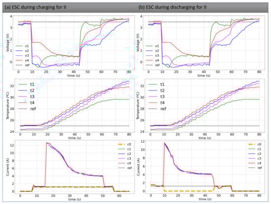
Figure 4.
Behavior of the main parameters of the four cells in series during an ESC in all cells.
Otherwise, C0 kept the standard charging current equal to 1100 mA. The CR controls this behavior. In the case of non-abuse, the reference current should be similar to C0. These experiments indicate the high difficulty of a BMS with few current sensors to find ESC located in isolated positions.
According to Figure 4a, the temperature of the four cells increased significantly, especially in cell #4. This effect can be explained by the voltage signature, in which cell #4 maintained the highest voltage of all cells during the ESC. A delta of about 7 °C was registered among the reference and the cell’s temperature, as observed in Figure 4a. The voltage of the other cells was close to 0 V during the abuse. In this way, if only one current sensor (C0) exists, verifying each cell’s voltage and temperature is necessary to identify this type of ESC.
The same experiment was carried out during the discharging process. Figure 4b shows that the voltage drops significantly during the abuse, as observed during the charging process. The current and temperature also had a similar signature for every cell. Otherwise, the current of C0 was zero during the abuse. This effect occurs because the current of the packing flow only from cell #1 to cell #4 and cannot deliver energy for the load. In a case without this type of abuse, the DR should maintain the reference current at 1100 mAh. Then, for this configuration, the behavior of the current is different (0 A for it) than for the charging process, where it was equal to 0.5 C during the ESC.
For configuration III, ESC abuse was applied in two series-connected cells. As observed in the last experiment, two tests were used: one during charging and the other during discharging.
During charging, Figure 5a shows the high current close to 14 A for cells #1 and #2 under abuse at the beginning. As time passed, the current decayed to close 4 A. Cells #3 and #4, registered by C3, C4, and C0, show the standard current of 1100 mA (as observed in the reference).
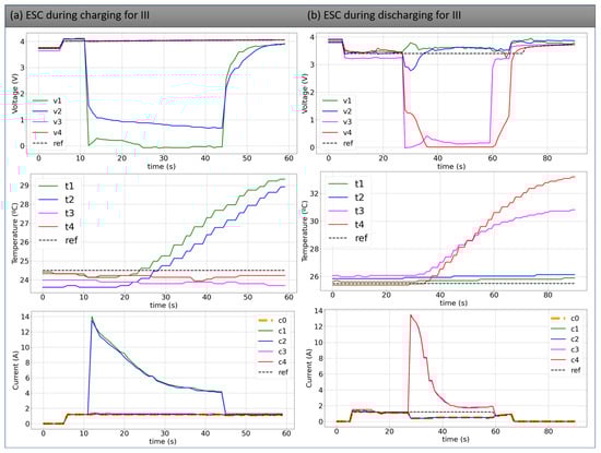
Figure 5.
Behavior of the main parameters of the four cells in series during an ESC in cells #1 and #2 during charging and an ESC in cells #3 and #4 during discharging.
During the abuse, the voltage of cells #1 and #2 dropped below 1 V for cell #2 and 0 V for cell #1. On the other hand, cells #3 and #4 were charged with 0.5 C, as also observed in the reference. This effect can also be observed in the temperature signature. The temperatures of cells #1 and #2 increased by about 7 °C while the others stayed close, as observed in the reference.
On the other hand, Figure 5b shows the signatures of the main parameters of the cells for the experiment in configuration III. In this case, the ESC was applied for cells #3 and #4. The voltage dropped to close to 0 V for cells #3 and #4 while remaining close to 3.6 V for the other cells and the reference.
In addition to that, the temperature of cell #4 increased above 32 °C in less than 30 s, and the temperature of cell #3 increased to 30 °C. Both rising are distinct from the temperature of cells #1 and #2 and the reference that remained close to 25 °C.
Figure 5b shows similar current behavior for the cells under abuse. The current of the other cells decreased and softened to 500 mA. This dropout happens because the packing cannot supply energy at the standard current magnitude (0.5 C) with only two cells available. Thus, C0 can be used as an indicator of this type of abuse because, in a normal condition, the reference current should be equal to 0.5, as observed in the picture.
Then, for configuration III, the voltage and temperature of the cell are essential to understand the presence and the location of ESC during the charging process. For the discharging cycle, the current sensor C0 can indicate the presence of an ESC in the packing. Nevertheless, with the addition of the temperature and the voltage, it is possible to find the location of the abuse.
For configuration IV, a series connection of two modules containing two cells in parallel was replaced by ESC for 30 s during the charging and discharging. Figure 6a shows that the voltage of cells #1 and #2 decays close to 1 V, while the other cells remain constantly (as the reference) supplied for the external source.
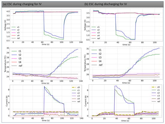
Figure 6.
Behavior of the main parameters of the four cells in parallel during an ESC in cells #1 and #2.
Furthermore, the temperature rises significantly above 28 °C for cell #1 and above 29.5 °C for cell #2. As already observed, the temperature of the cells without ESC (cells #3 and #4) maintains its temperature close to 25 °C, as also observed in the reference.
The current of the cells under ESC began the abuse with a magnitude above 8 A for both cells and decayed to about 4 A, as registered for cells #1 and #2.
Despite that, the current register by C0 is about 1100 mA and controlled by the CR, similar to the reference. This current is divided between the cells in the module. As observed in Figure 6a, the sum of the current of cells #1 and #2 totaled 1100 mA before and after the abuse. On the other hand, cell #4 receives lesser energy compared with cell #3. This phenomenon is observed before, during, and after the ESC because although the same capacity, cell #4 began the experiment with more level of voltage than cell #3.
Similar effects are seen in Figure 6b during discharging. The figure shows that the voltage also decays to close to 1 V, and the temperature increase in a similar signature compared to what was observed in Figure 6a. The current registered by C0 maintained equal to 1100 mA before and after the abuse but could not support the current at 0.5 C (reference current value) during the abuse because the pack had only two available cells (#3 and #4) during the abuse.
Both experiments show that the voltage and the temperature can indicate the type and location of abuse in this configuration. As observed in the investigations of configuration III, the current supplied by the packing cannot maintain the standard demand during the abuse because only two cells are available.
Finally, configuration VI was applied during the charging and discharging process. According to Figure 7a, all voltage drops are below 1 V during the charging process. All temperatures rose to around 30 °C, and the current reached close to 12 A at the beginning of the experiment. Despite that, with time, the current of C1 and C2 dropped out until 4 A, and C1 and C2 indicated a final current close to 1.1 A.
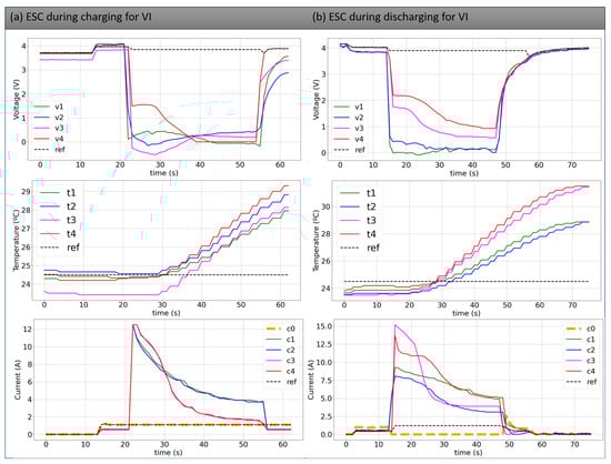
Figure 7.
Behavior of the main parameters of the four cells in parallel during an ESC in all cells.
The current of C3 and C4 was higher than C1 and C2 at the beginning of the test, but about 10 s under the ESC, these two currents decayed below C1 and C2. Despite that, the reference was 1.1 A, equal to the current registered by C0. As already observed, C0 was not able to detect this type of ESC during the charging process.
On the other side, Figure 7b indicates the main behaviors of ESC for configuration VI during the discharging process. The voltages in a normal experiment should be close to 3.8 V as observed by the reference. Although, the following voltages were observed: between 1 and 2 V for cells #3 and #4 and close to 0 V for cells #1 and #2 during the discharging.
This effect is also observed in the temperature signature. While the reference should be 25 °C, cells #3 and #4 registered higher temperatures (reached 32 °C) than the other cells (reached 29 °C for cells #3 and #4).
The temperature behavior can be explained by the currents. The current of cells #3 and #4 was higher than #1 and #2 at the beginning of the ESC, which indicates that these cells (#3 and #4) supplied more energy. In addition to that, an interesting behavior was observed for cells #3 and #4. C4 indicated the initial peak about 13 A and C3 above 15 A. Despite that, the current C3 decreased to close to 5 A with about 11 s under ESC, while C4 registered a current above 5 V after 30 s of ESC.
Finally, C0 registered 0 A when configuration VI was applied. This behavior is different from the reference value of the current and can be used to detect ESC abuse in the pack.
In general, for ESC abuses, the abuses may significantly increase the cell’s temperature independent of the configuration. The voltage sensor can also suggest a presence of an ESC in the packing. Nonetheless, the ESC is observed by current sensors if there are several sensors between the cells. In a real case, sensor C0 detects a soft variation during discharging due to the reduced energy available to supply the load but can not identify it during the charging process.
4.2. Analyzes of OC
Different from ESC analyses, for OC, three configurations have been implemented. Configuration I, in which all cells were in series and charged above the safe, high threshold. Figure 8a shows the main parameters during the abuse. The voltage curve shows that cell #3 is under OC, while the others were not under failure. The reference used is the threshold equal to 4.2 V.
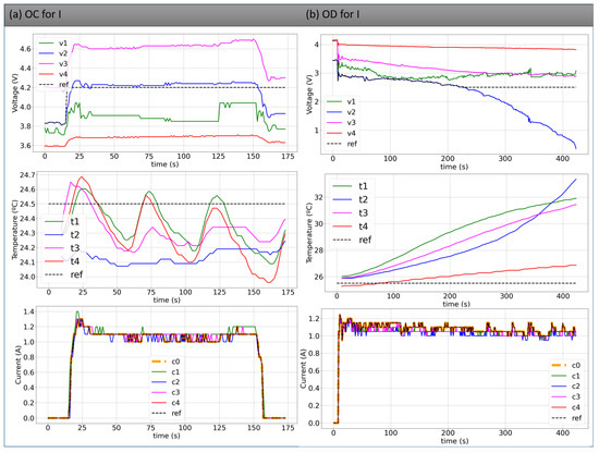
Figure 8.
Behavior of the main parameters of the four cells in series during an OC in cell #3 and OD for cell #2.
Furthermore, the temperatures remained slightly during the OC. This happens because, according to Gotz et al. [], a cell needs to take a long time under OC to its temperature rise. Despite that, the reference temperature is about 25 °C.
On the other hand, all current sensors registered a similar signature equal to the reference. Then, for this type of abuse, only the voltage should be considered to identify a single OC in the pack.
When the OC is applied in parallel, like in configuration IV, two cells with similar voltage are present in each module. According to Figure 9a, the current of each cell in the packing is different. The internal characteristics of the cell can explain this effect, such as internal resistance, capacity, and level of voltage. Due to the parallel arrangement, the sum of C1 and C2 is equal to the sum of C3 and C4 and consequently equal to C0 and the reference. Despite that, C0 is not able to identify this type of abuse.
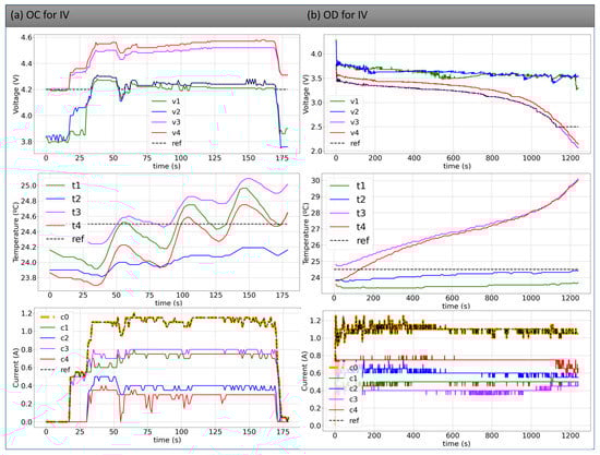
Figure 9.
Behavior of the main parameters of the four cells in parallel during an OC in cell #3 and cell #4 and during an OD for cells #3 and #4.
As observed in the last experiment, the temperature of the cells remained within the established range, close to the ambient temperature (reference value). Therefore, the voltage of the cells can be used to understand an OC in this configuration.
Although, the parallel. Despite that, as in a parallel configuration, all cells tend to maintain the same level of voltage; before the cells go to the abuse, one will charge the other so both stay at the same level of energy, as observed in Figure 9a,b. In this situation, in the parallel connection, one cell will discharge or charge more current than the other until they have the same level of energy.
Finally, OC was applied to configuration V. In this experiment, the different voltages at the module observing the current signatures are more visible. As observed in Figure 10a, at the same time, cell #4, with low voltage, receives more current than cell #3, with high energy. This behavior is observed in cells #1 and #2 (as related in the previous paragraph). Despite that, C0 cannot observe the variation of the input current because it has the same reference value.
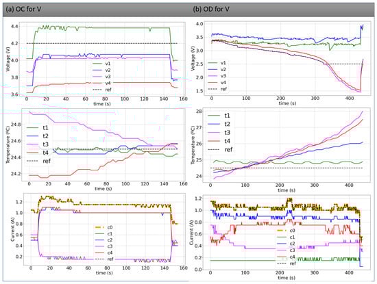
Figure 10.
Behavior of the main parameters of the four cells in parallel during an OC in cells #1 and #3 and during OD for cells #1 and #3.
Thus, it is possible to state that observing the cell’s voltage is necessary to identify and locate the cell under OC at different configurations. Under OC, the temperature takes a long time to increase, as observed by Gotz et al. [], and the current can not indicate OC abuse in the cells.
4.3. Analyzes of OD
Finally, the work presents the results of the abuses of OD in packing. As observed in OC abuses, three configurations have been implemented with OD: I, IV, and V.
Firstly, in configuration I, one cell began the test with a lower voltage than the other three. When a discharging current of 1.1 A was applied in the experiment, the voltage of cell #2 decreased more than other cells. Despite that, the series arrangement maintained the current constant equal to 1.1 A, similar to the reference, which could not identify this type of failure in the packing. The test was carried out for two minutes after one voltage cell was below 2.5 V.
As observed in Figure 8a, the cell’s temperature under abuse rose significantly compared with the others and achieved about 36 °C. Despite that, the temperature of cells #1 and #3 increased to 32 °C (normal behavior for cells under discharging process as observed in the study of Gotz et al. []). Thus, the combination of voltage and temperature should be used to identify OD failures in this type of configuration.
Additionally, Figure 9b indicates the experiments with OD for configuration IV. According to the picture, both voltages (cell #3 and #4) suffered from the abuse, and their voltages achieved values below 2 V (two minutes after the voltage of the first cell was below 2.5 V). During this failure, their temperature rose to about 30 °C, and the temperature of the other cells remained close to the controlled ambient (reference value). The study of Gotz et al. [] shows that the temperature increases more when the SOC decreases. Thus, as the voltage of cells #1 and #2 were above 3.5 V, their temperature remained close to the reference. Nothing could be observed in the current signature.
Finally, OD was applied to configuration V. Figure 10b indicates that during the discharging process, despite the voltage of the two cells in the module having different voltage levels, the cell with high energy supplies more energy than the others with low voltage. This effect equalizes the voltage of the cells during the discharging process. Consequently, both cells (in this case, #3 and #4) come below 2.5.
The temperature signature indicates the OD present in cells. Despite the temperature increasing naturally during the discharging (especially when the resistance is higher when the cell has a voltage lower than 3 V []), the temperature increased more under OD abuse. In addition to that, current sensor C0 was close to the reference and could not indicate the presence of abuse.
Therefore, it is possible to state that for finding OD in a LIB packing, it is necessary to analyze the voltage and temperature of the cell.
Compared to the literature, this study presents the application of several experiments to find failures in packing LIB with different configurations and arrangements. In general, this work is more complete because it demonstrated analyses to identify three types of failures (ESC, OC, and OD) with a limited number of sensors, while the works of Zheng et al. [], Xu et al. [], Kang et al. [], Li and Wang [], and Xia and Mi et al. [] worked especially with techniques to identify fault sensors and measurement in a packing. According to the authors, the development has been applied to experimental data and has 100% accuracy. Despite that, our proposed idea is to give insights and correct solutions to find failures in a pack of batteries with limited sensors.
5. Conclusions
Lithium-ion batteries are state-of-the-art technology for ESS. This type of battery has been a significant demand in the last years, mainly due to the incentives of the governments and the necessity of a change to fossil fuel vehicles for EVs.
This technology presents several advantages but must operate under safe and controlled conditions. Despite that, LIB is assembled by cell, module, or packing arrangements. Therefore, a packing has several cells connected in series or parallel, making the monitoring system more complex.
Therefore, this work presented a collection of experiments applying abuses in the cells under different abuses. As observed in the literature, it is difficult to find isolated failures in a pack of batteries with different configurations and limited sensors. Then, several experiments were carried out to generate enough data for the analysis. The results indicated that the voltage and temperature of the cell could identify an ESC during the charging process. On the other side, during the discharging process, the current packing reduction can signal the presence of an ESC.
Only the voltage can be used for OC abuses to indicate a failure in the cell. This situation is observed because the cell under OC takes a long time to increase the temperature. On the other hand, the cells’ temperature is higher for OD abuses. Then, the combination of voltage and temperature can be an indicator of the presence of OD in the packing of batteries.
This investigation demonstrated how isolated failures can be found in packs of batteries even with few available sensors, analyzing the signatures of the main measurement parameters. The results motivated the automatic investigation of the failures with artificial intelligence (AI) techniques. The results will be used to build protection and diagnostics mechanisms with data-driven and machine-learning approaches to automatically find the failures in packing LIB in future works.
Author Contributions
Conceptualization, J.D.G., M.B. and F.C.C.; methodology, J.D.G., J.E.M.N. and J.R.G.; software, J.R.G., H.V.S. and E.R.V.; validation, M.H.N.M., M.A.M. and H.V.S.; formal analysis, M.H.N.M., M.A.M., H.V.S. and F.C.C.; validation, M.H.N.M., M.A.M. and H.V.S.; investigation, J.D.G., M.B. and J.E.M.N.; resources, M.H.N.M., M.A.M. and A.I.; data curation, M.B. and F.C.C.; writing—original draft preparation, J.D.G., T.M.B.M. and F.C.C.; writing—review and editing, H.V.S., M.H.N.M., M.A.M. and A.I.; visualization, J.R.G., J.E.M.N. and M.A.M. supervision, M.B. and F.C.C.; project administration, F.C.C.; funding acquisition, M.H.N.M. and A.I. All authors have read and agreed to the published version of the manuscript.
Funding
This study was financed in part by the Coordenação de Aperfeiçoamento de Pessoa de Nível Superior—Brasil (CAPES)—Finance Code 001. The authors thank the Brazilian National Council for Scientific and Technological Development (CNPq), process number 408053/2022-4 and 310862/2022-1, Araucária Foundation, process number 51497, and Fundep Rota 2030 Public Call #01/2020, Agreement #27192.03.01/2020.16-00, for their financial support.
Conflicts of Interest
The authors declare no conflict of interest.
References
- Liu, W.; Placke, T.; Chau, K. Overview of batteries and battery management for electric vehicles. Energy Rep. 2022, 8, 4058–4084. [Google Scholar] [CrossRef]
- Bryła, P.; Chatterjee, S.; Ciabiada-Bryła, B. Consumer Adoption of Electric Vehicles: A Systematic Literature Review. Energies 2023, 16, 205. [Google Scholar] [CrossRef]
- Nascimento, R.; Ramos, F.; Pinheiro, A.; Junior, W.d.A.S.; Arcanjo, A.M.; Filho, R.F.D.; Mohamed, M.A.; Marinho, M.H. Case Study of Backup Application with Energy Storage in Microgrids. Energies 2022, 15, 9514. [Google Scholar] [CrossRef]
- Ramos, F.; Pinheiro, A.; Nascimento, R.; de Araujo Silva Junior, W.; Mohamed, M.A.; Annuk, A.; Marinho, M.H. Development of Operation Strategy for Battery Energy Storage System into Hybrid AC Microgrids. Sustainability 2022, 14, 13765. [Google Scholar] [CrossRef]
- de Araujo Silva Júnior, W.; Vasconcelos, A.; Arcanjo, A.C.; Costa, T.; Nascimento, R.; Pereira, A.; Jatobá, E.; Filho, J.B.; Barreto, E.; Dias, R.; et al. Characterization of the Operation of a BESS with a Photovoltaic System as a Regular Source for the Auxiliary Systems of a High-Voltage Substation in Brazil. Energies 2023, 16, 1012. [Google Scholar] [CrossRef]
- Costa, T.; Arcanjo, A.; Vasconcelos, A.; Silva, W.; Azevedo, C.; Pereira, A.; Jatobá, E.; Filho, J.B.; Barreto, E.; Villalva, M.G.; et al. Development of a Method for Sizing a Hybrid Battery Energy Storage System for Application in AC Microgrid. Energies 2023, 16, 1175. [Google Scholar] [CrossRef]
- Ahoutou, Y.; Ilinca, A.; Issa, M. Electrochemical Cells and Storage Technologies to Increase Renewable Energy Share in Cold Climate Conditions—A Critical Assessment. Energies 2022, 15, 1579. [Google Scholar] [CrossRef]
- Chen, Y.; Kang, Y.; Zhao, Y.; Wang, L.; Liu, J.; Li, Y.; Liang, Z.; He, X.; Li, X.; Tavajohi, N.; et al. A review of lithium- ion battery safety concerns: The issues, strategies, and testing standards. J. Energy Chem. 2021, 59, 83–99. [Google Scholar] [CrossRef]
- Hu, X.; Zhang, K.; Liu, K.; Lin, X.; Dey, S.; Onori, S. Advanced Fault Diagnosis for Lithium-Ion Battery Systems: A Re- view of Fault Mechanisms, Fault Features, and Diagnosis Procedures. IEEE Ind. Electron. Mag. 2020, 14, 65–91. [Google Scholar] [CrossRef]
- Daowd, M.; Antoine, M.; Omar, N.; Lataire, P.; Van Den Bossche, P.; Van Mierlo, J. Battery Management System—Balancing Modularization Based on a Single Switched Capacitor and Bi-Directional DC/DC Converter with the Auxiliary Battery. Energies 2014, 7, 2897–2937. [Google Scholar] [CrossRef]
- Ramkumar, M.; Reddy, C.; Ramakrishnan, A.; Raja, K.; Pushpa, S.; Jose, S.; Mani, J. Review on Li-Ion Battery with Battery Management System in Electrical Vehicle. Adv. Mater. Sci. Eng. 2022, 2022, 1–8. [Google Scholar] [CrossRef]
- Galvão, J.R.; Calligaris, L.B.; de Souza, K.M.; Gotz, J.D.; Junior, P.B.; Corrêa, F.C. Hybrid Equalization Topology for Battery Management Systems Applied to an Electric Vehicle Model. Batteries 2022, 8, 178. [Google Scholar] [CrossRef]
- Siqueira, H.; Macedo, M.; Tadano, Y.d.S.; Alves, T.A.; Stevan, S.L., Jr.; Oliveira, D.S., Jr.; Marinho, M.H.; Neto, P.S.d.M.; Oliveira, J.F.d.; Luna, I.; et al. Selection of temporal lags for predicting riverflow series from hydroelectric plants using variable selection methods. Energies 2020, 13, 4236. [Google Scholar] [CrossRef]
- Tran, M.K.; Fowler, M. A Review of Lithium-Ion Battery Fault Diagnostic Algorithms: Current Progress and Future Challenges. Algorithms 2020, 13, 62. [Google Scholar] [CrossRef]
- Zheng, C.; Chen, Z.; Huang, D. Fault diagnosis of voltage sensor and current sensor for lithium-ion battery pack using hybrid system modeling and unscented particle filter. Energy 2020, 191, 116504. [Google Scholar] [CrossRef]
- Xu, J.; Wang, J.; Li, S.; Cao, B. A Method to Simultaneously Detect the Current Sensor Fault and Estimate the State of Energy for Batteries in Electric Vehicles. Sensors 2016, 16, 1328. [Google Scholar] [CrossRef]
- Zhang, C.; Jiang, Y.; Jiang, J.; Cheng, G.; Diao, W.; Zhang, W. Study on battery pack consistency evolutions and equilibrium diagnosis for serial- connected lithium-ion batteries. Appl. Energy 2017, 207, 510–519. [Google Scholar] [CrossRef]
- Zhang, Z.; Cai, Y.Y.; Zhang, Y.; Gu, D.J.; Liu, Y.F. A Distributed Architecture Based on Microbank Modules With Self- Reconfiguration Control to Improve the Energy Efficiency in the Battery Energy Storage System. IEEE Trans. Power Electron. 2016, 31, 304–317. [Google Scholar] [CrossRef]
- Wei, Z.; Zhao, J.; He, H.; Ding, G.; Cui, H.; Liu, L. Future smart battery and management: Advanced sensing from external to em-bedded multi-dimensional measurement. J. Power Sources 2021, 489, 229462. [Google Scholar] [CrossRef]
- Kang, Y.; Duan, B.; Zhou, Z.; Shang, Y.; Zhang, C. Online multi-fault detection and diagnosis for battery packs in electric vehicles. Appl. Energy 2020, 259, 114170. [Google Scholar] [CrossRef]
- Ghiji, M.; Novozhilov, V.; Moinuddin, K.; Joseph, P.; Burch, I.; Suendermann, B.; Gamble, G. A Review of Lithium-Ion Battery Fire Suppression. Energies 2020, 13, 5117. [Google Scholar] [CrossRef]
- Maiser, E. Battery packaging—Technology review. AIP Conf. Proc. 2014, 1597, 204–218. [Google Scholar] [CrossRef]
- Yang, R.; Xiong, R.; Shen, W. On-board diagnosis of soft short circuit fault in lithium-ion battery packs for electric vehicles using an extended Kalman filter. CSEE J. Power Energy Syst. 2022, 8, 258–270. [Google Scholar] [CrossRef]
- Li, X.; Wang, Z. A novel fault diagnosis method for lithium-Ion battery packs of electric vehicles. Measurement 2018, 116, 402–411. [Google Scholar] [CrossRef]
- Xia, B.; Mi, C. A fault-tolerant voltage measurement method for series connected battery packs. J. Power Sources 2016, 308, 83–96. [Google Scholar] [CrossRef]
- Hong, J.; Wang, Z.; Liu, P. Big-Data-Based Thermal Runaway Prognosis of Battery Systems for Electric Vehicles. Energies 2017, 10, 919. [Google Scholar] [CrossRef]
- Xu, B.; Kong, L.; Wen, G.; Pecht, M.G. Protection Devices in Commercial 18650 Lithium-Ion Batteries. IEEE Access 2021, 9, 66687–66695. [Google Scholar] [CrossRef]
- Cai, T.; Mohtat, P.; Stefanopoulou, A.G.; Siegel, J.B. Li-ion Battery Fault Detection in Large Packs Using Force and Gas Sensors. IFAC-PapersOnLine 2020, 53, 12491–12496. [Google Scholar] [CrossRef]
- Wang, J.; Zhang, S.; Hu, X. A Fault Diagnosis Method for Lithium-Ion Battery Packs Using Improved RBF Neural Network. Front. Energy Res. 2021, 9, 702139. [Google Scholar] [CrossRef]
- Ouyang, D.; Chen, M.; Liu, J.; Wei, R.; Weng, J.; Wang, J. Investigation of a commercial lithium-ion battery under overcharge/over- discharge failure conditions. RSC Adv. 2018, 8, 33414–33424. [Google Scholar] [CrossRef] [PubMed]
- Maleki, H.; Howard, J.N. Effects of overdischarge on performance and thermal stability of a Li-ion cell. J. Power Sources 2006, 160, 1395–1402. [Google Scholar] [CrossRef]
- Li, A.; Yuen, A.C.Y.; Wang, W.; Weng, J.; Lai, C.S.; Kook, S.; Yeoh, G.H. Thermal Propagation Modelling of Abnormal Heat Generation in Various Battery Cell Locations. Batteries 2022, 8, 216. [Google Scholar] [CrossRef]
- Zhai, H.; Chi, M.; Li, J.; Li, D.; Huang, Z.; Jia, Z.; Sun, J.; Wang, Q. Thermal runaway propagation in large format lithium ion battery modules under inclined ceilings. J. Energy Storage 2022, 51, 104477. [Google Scholar] [CrossRef]
- Gotz, J.D.; Galvão, J.R.; Werlich, S.H.; Silveira, A.M.d.; Corrêa, F.C.; Borsato, M. Reducing the Capacity Loss of Lithium-Ion Batteries with Machine Learning in Real-Time—A Study Case. Machines 2022, 10, 1114. [Google Scholar] [CrossRef]
Disclaimer/Publisher’s Note: The statements, opinions and data contained in all publications are solely those of the individual author(s) and contributor(s) and not of MDPI and/or the editor(s). MDPI and/or the editor(s) disclaim responsibility for any injury to people or property resulting from any ideas, methods, instructions or products referred to in the content. |
© 2023 by the authors. Licensee MDPI, Basel, Switzerland. This article is an open access article distributed under the terms and conditions of the Creative Commons Attribution (CC BY) license (https://creativecommons.org/licenses/by/4.0/).