Abstract
One of the key postulates of the modern automotive industry is the increase in production efficiency while minimizing costs. In the opinion of experts from the automotive industry, meeting this condition may be the first stage on the way to preventing waste generation and implementing a circular economy model. The article presents a case study of issues related to the lean manufacturing methodology in terms of the impact of shortening the changeover time of the assembly line on the overall production efficiency. The presented considerations focus on the optimization of the production process using the SMED (Single Minute Exchange of Die) technique of a selected spare part. From the point of view of the Lean Manufacturing concept, the main goal of the SMED technique is to increase the flexibility of responding to changing customer needs by shortening the changeover times and faster responses to changing orders. The article describes the stages of implementing the SMED method and its impact on the increase in the OEE (Overall Equipment Efficiency) index, which allows for the percentage recognition of the degree of machine park utilization, which is one of the key factors for assessing energy efficiency. In addition, the benefits that have been achieved by using this method in terms of time and economy have been presented. The theoretical aspects related to the method used were supplemented with its practical implementation in order to improve the changeovers in a manufacturing company in the automotive industry. Based on the obtained test results, an analysis of the effectiveness of the measures taken to reduce the changeover time was carried out. The use of the SMED methodology contributed to a significant reduction in changeover time—by as much as 291.4 s. The burden on operators was significantly reduced—the total time and number of operations performed by them (both internal and external) was reduced. Operator paths have also been shortened using simple procedures such as changing the layout of the lines and modifying the changeover tool trolleys and tool locking system at the stations. The presented research may be helpful in answering the question whether the implementation of the SMED idea may be the key to effective resource management and, at a later stage, to the implementation of the circular economy model. In addition, the research results can find their practical application among both manufacturers of spare parts and the vehicles themselves, considering introducing process changes on their production lines in order to increase production efficiency and implementing the idea of industrial sustainability.
1. Introduction
The modern automotive industry is one of the most dynamically developing markets of the 21st century. The prevailing socio-economic situation and the processes of mutual competition in this market require the introduction of new forms of organization of the production process, in line with current trends. For companies specializing in the production of spare parts to develop, they then must adapt to the dynamic changes taking place in the environment, which are triggered by the progressing globalization. In order to stay in such a competitive market, individual producers must use solutions that strengthen the effectiveness of achieving strategic goals [1]. In the case of assembling the same component, i.e., a given spare part for several manufacturers or vehicle models, it may be necessary to change the production line. [2,3,4]. Changeovers should be designed in a thoughtful and analytical way so that their times are as short as possible [5,6,7]. The work of operators and the sequence of actions used by them should be standardized, and operators should be trained and fully aware of their duties [8,9]. Therefore, the key to the success of manufacturing companies in the automotive industry is the introduction of a systemic way of thinking about production processes into their companies.
One of the methods of increasing production efficiency is the concept of lean manufacturing, which was developed in the automotive sector in Japan by Toyota Motor Company after the end of World War II [10,11,12]. It is known under the English name of lean management. It consists of reducing production costs by constantly eliminating waste and improving production processes. This concept was confirmed by its application in Japan and then in the USA. It turned out that Toyota was much more efficient than other European and American competitors [13,14,15]. The concept of lean manufacturing defines and categorizes wastes with Muda, which comprises overproduction, stocks, waiting times, shortages, unnecessary movements, and unnecessary transports [16]. The assumption is that reducing waste increases competitiveness through savings in the production organization process, thus being in line with the idea of a circular economy. However, the implementation of innovative solutions is associated with incurring costs. Therefore, in the current difficult market reality, at the first stage, most activities of entities from the automotive industry focus on issues related to changes in the organization of production processes, the purposes of which are to increase efficiencies while minimizing costs.
The novelty of the article is the development of an integrated model for the implementation of the SMED method in the example of an automotive company, taking into account changes in the environment. The company should adapt to these changes by using innovative structures for changing the machine park to the assumptions of the sustainable circular economy. By proposing a model, the authors indicate the processes in the analyzed enterprise that require improvement and indicate ready-made solutions, verified in real conditions, as part of the innovative economy. There are no studies in the literature that would refer to shortening the machine park changeover time in order to improve production efficiency and organization of the production of spare parts in a vehicle’s production process. Therefore, this article fills the research gap and is a concrete example of how to modify the manufacturing process and machinery park with the use of SMED tools to increase production efficiency in the automotive industry. As a result of these considerations, a model of effective selection of the strategy for organizing the production processes of a given spare part was created and adapted to the individual situational conditions of an entity from the automotive industry, creating a new area for analyses on the effectiveness of implementing solutions in the field of organizing the production processes of individual spare parts. The article aims to analyze the implementation of the SMED method on an assembly line of car headlights for the example of one of the leading manufacturers and to indicate the savings in time and money. The main effect of the introduced changes is to generate time savings that can be used to produce more products. Using the SMED method, an analysis of the initial state was prepared, taking into account the activities performed during the changeover, tools used in the changeover process, and layout of the assembly line [17]. The analysis of the above-mentioned issues showed areas that should be modified. The content of the article gives a fresh, innovative, and, at the same time, practical look at the basic principles of minimizing time wastage in production plants and the resulting financial benefits [18,19]. Unlike other studies available in the literature on the subject, in this work, the authors analyzed the actual production process by implementing solutions that were used in practice, more specifically in the automotive industry. In addition, the article provides the necessary knowledge on the use of Lean Manufacturing tools and the SMED method in the automotive industry to optimize production processes in the field of assembly of individual spare parts, which is the first step in achieving the company’s goal of increasing assortment flexibility and the ability to compete with time.
The rest of the article is as follows: Section 2 presents a global and national review of the literature on lean manufacturing and the use of SMED methodology in optimizing production processes. Section 3 describes the research methodology used for the Lean Manufacturing analysis. Section 4 describes the results and discusses them. Finally, Section 5 describes the conclusions of the research.
2. Literature Review
The SMED (Single Minute Exchange of Die) methodology is a set of techniques and tools that enable shortening the changeover times of machines, devices, and production processes. The main goal of the method, developed by the Japanese engineer Shigeo Shingo, is to carry out each changeover in a unit number of minutes (up to 10 min) by dividing and simplifying the whole process so that the changeovers are made with the use of as few tools as possible. The basic assumption of the SMED method developed by Shigeo Shingo in the 1950s and 1960s is the maximum reduction in machine changeover time to a single-digit value below 10 min and a clear separation of internal and external activities [20,21,22]. The Japanese engineer Shigeo Shingo (1909–1990) is considered one of the greatest experts in the field of production management; he is known as the creator of SMED and the Toyota production system [23]. It was he who divided the activities into internal and external. This method is called SMED and comes from the English name Single Minute Exchange of Die (single-digit mold changeover time expressed in minutes) [24,25,26]. Retooling is a process that is related to the preparation of a machine or a series of interconnected machines for the production of a new product [27]. It consists of replacing tools and preparing a new production process [28,29,30]. The enterprise does not gain any added value during its lifetime. The changeover time is presented as follows in the graphic in Figure 1. This is the time between the production of the last good product from the batch of the previous reference and the first good item from the next batch. Retooling is the process of preparing the production of a new reference, during which components for the new version of the product must be provided, and machines must be retooled [31,32].

Figure 1.
Visualization of changeover time. Source: own study.
The conversion of machines takes place on production lines. The production line is a set of machines and stations arranged in accordance with the sequence of operations performed in the technological process. The number of stations depends on the needs and the manufactured details or assemblies [33,34]. The product passes through the workstations in the so-called production process. The concept of line production is characterized by the fact that machines are arranged to form lines [35]. Its arrangement is characterized by the fact that the product passes through successive, adjacent production stations arranged in a characteristic way [36,37]. An exemplary arrangement of stations on production lines is shown in Figure 2. Production on the line can be partially or fully automated. When designing the line, the SMED methodology should be taken into account, which contributes to shortening the changeover time of machines and devices and increasing the efficiency of the line.
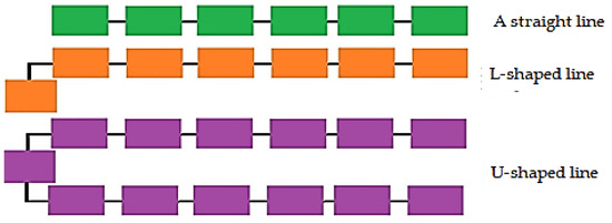
Figure 2.
Anthe ample of positioning of workstations on production lines. Source: own study.
Quick tool change is important for the company because it is possible to adapt machines to new production tasks and adapt production to customer requirements in a short time [38,39]. Reducing the changeover time brings many benefits: shorter delivery times, competitive advantages, and increases in production without increasing employment and replacing machines. Reducing the changeover time brings tangible profits and may increase the company’s profitability [40]. The funds obtained through the implementation of the SMED method can be used for new investments, training, and marketing. The creators of the SMED method had specific goals in mind: reducing the cost of retooling, and the ability to offer customers a variety of products that meet individual needs and tastes [41]. This could not be achieved with mass production. The SMED method excludes defects resulting from mass production. Using this method, one could produce small batches of products, increase flexibility, reduce inventory, speed up lead times, increase machine and employee productivity, and reduce downtime. The operations performed during the changeover time reduction are divided into four stages, which consist of [42,43]:
- -
- Collection and control of tools and machines so that they are in the right place and work properly;
- -
- Separation of internal and external reinforcement;
- -
- Transforming internal processes into external processes. During this stage, a re-analysis of the changeover is performed. It is checked whether all internal activities have been properly qualified. Methods are sought to transform internal operations into external ones;
- -
- Improvement of all aspects of changeover, including analysis of the assembly line layout, registration of all activities performed in the changeover process, and measurement of changeover time for the state after modernization.
In the initial phase of SMED, it is recommended to record the changeover process with a camera. Recording should accompany the changeover process from beginning to end, and the cameraman should carefully follow every movement of employees. It is important to analyze the collected material at the meeting of the SMED group and to invite engineers, operators, and other employees who carried out the changeover to the discussion [44]. It is important that the operators accurately name the activities and their durations. Designated people can make Spaghetti diagrams that graphically show time wasted during machine changeover. On the layout, you should draw all the roads it covers. Often, analysis of these graphs shows that operators cover long distances during changeovers. The maximum shortening of the operators’ paths brings measurable benefits. Based on the SMED analysis, it is possible to analyze all external and internal activities that operators perform at specific workstations. The task of the implementation group at this stage is to indicate which activities can be performed before or after the changeover. The effect of such an analysis is the transformation of some internal activities into external activities. Thus, SMED makes it possible to implement a continuous flow of products, without loss of efficiency or long waiting times. Such activities contribute to the improvement of quantitative and qualitative indicators. The duration of changeover is an element that determines the flexibility of the production process, and properly organized activities and designed flows at the workplace allow for its shortening. A useful tool used to optimize the changeover process is the checklist. The list eliminates time wasted searching for tools unnecessarily. The list should include the necessary tools and materials needed for conversion [45]. From such a list, the operator learns the materials, tools, and when they will be needed during changeover. The list also includes recommendations for checking the technical condition of tools. During the analysis, attention is paid to improving transport.
The use of the presented technique results in a reduction in the cost of unit production of products, shortening the order fulfillment time, increasing the use of the working time of operators and machines, and minimizing downtime on the production line [46]. Among the additional benefits, the increase in the ergonomics of work on the line by enlarging the working space and standardizing the tools used for changeover is worth mentioning, as this was also confirmed by the authors in their research [47,48,49,50]
3. Materials and Methods
3.1. Case study—Initial State Analysis
In accordance with the SMED methodology, an analysis of the original condition of the assembly line was carried out by observing the condition of the line during production and changeover (Figure 3). The observation was aimed at searching for time losses. This was performed by observing the changeover process, measuring the duration of all operator activities. The work of the operators was examined by means of monitoring installed on the line. The operators were not informed in advance about the upcoming observations and measurements. The process of assembling vehicle lamps on the assembly line and the retooling process of a leading manufacturer were analyzed. On the basis of the data obtained during the observation, tabular lists of times allocated to individual operations (operators’ activities) were prepared. During the observation, attention was also paid to the organization of workstations in accordance with the safety rules and the availability of tools for operators. Research has shown that the current work organization process on assembly lines is not free from the Muda phenomenon in the areas of unnecessary movement of operators, time loss, and prolongation of the production process. Table 1 presents a description of the work activities performed by individual operators at individual workstations. The included description makes it possible to identify the performed tasks defined by individual symbols.
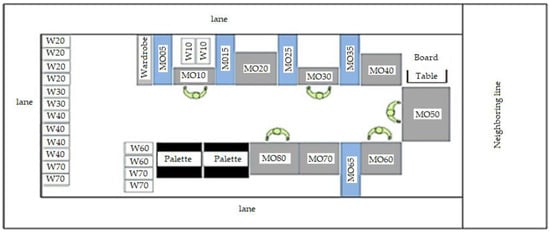
Figure 3.
The original condition of the assembly line before applying the reduction in the changeover time of the headlamp assembly line using the SMED methodology. Source: own study.

Table 1.
Description of the symbols of workstations performed by individual operators.
3.2. Design and Implementation of a New Changeover Process
In order to shorten the path traveled by the operators during the changeover, a new innovative layout of the production line was designed by the authors, shown in Figure 4. The storage place for tools was marked and located in a way that facilitated the removal of trolleys by operators, without disturbing or getting in each other’s way. When designating new tool storage areas, sections for trolleys for individual workstations were precisely marked. Trolleys for conversion were clearly and comprehensibly marked. The design of the automatic station trolleys changed. The previous four carts, two for the lower tools and two for the upper tools (Figure 5), were replaced by two merged carts (Figure 6). They could operate the lower and upper stations simultaneously. Replacement of handcarts was one of the stages of modernization of the production line. The trolleys were changed to those that had comprehensive and fully automated tools and assembly accessories adapted to the production cells. The trolleys were fully automated and of standardized dimensions that fit into modern internal transport devices as part of tool management. Trolleys for conversion to lower and upper tools were adapted to the dimensions of workstations, the functionalities of which allowed for convenient and safe changeovers.
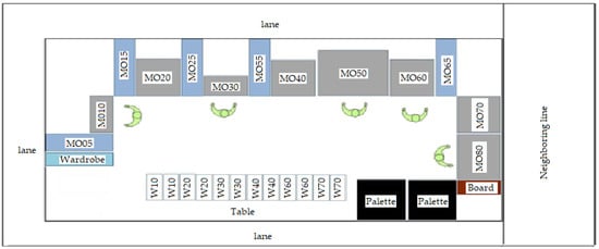
Figure 4.
The state of the assembly line after the reduction in the changeover time of the headlamp assembly line using the SMED methodology. Source: own study.
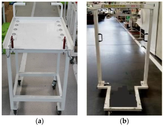
Figure 5.
Trolley for converting the lower and upper tools: (a) trolley for changing the lower tool, (b) trolley for changing the upper tool. Source: own study.
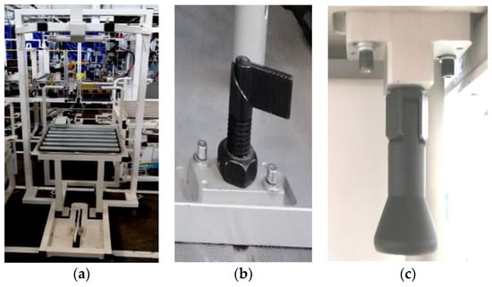
Figure 6.
Modified cart with latches for converting the lower and upper tools: (a) trolley for changing the lower and upper tools, (b) lower tool latch, (c) upper tool latch. Source: own study.
4. Results and Discussion
4.1. Analysis of the Initial State before Implementation
There were five feeders with components on the line: MO05, MO15, MO25, MO35 and MO65, which were fed by line feeders. The line feeder completed the missing components and replaced them with the new components of the new product reference. Five operators operated manual assembly stations, automatic stations, robotic cells (gluing cells), and automatic and visual control stations. Their duties also included the control and packaging of finished products and the retooling of machines. After the observations, it was found that the production of lamps was in accordance with the standards. We were dealing with a smooth flow of one piece (one-piece flow), and the manufactured lamps left the production line in rhythmic, recurring intervals. The work on the tested line was balanced, which meant that the time of the operators’ work sequence was equal. The line worked in a takt of 42 s. The analysis of the changeover cycle for the initial state took into account all the activities of the operators in the specified period during their duration. Internal retooling included the activities that must have been performed when the machine or device being retooled was switched off. On the other hand, external changeovers were all those activities that could be performed before stopping the machine or after restarting the process converted to the production of a new type of product. Such a division had far-reaching consequences because it was internal changeovers that caused losses in machine operation efficiency and downtime, which resulted in extending production series. It was from the internal changeovers that the analyses and the process of shortening the changeovers most often began. Knowing the times of individual stages, one could start looking for system modernization. The times were measured between the individual stages of the process, and it was on their bases that remedial actions were taken to modernize the production processes. According to the SMED methodology, activities were divided into internal and external. The total time of all operator activities was 899.7 s. During this time, internal activities were performed in 368.4 s and external activities in 531.3 s (Figure 7). In total, 157 activities were performed, including 61 internal and 96 external related to the changeover process (Figure 8).
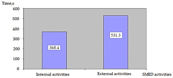
Figure 7.
Duration of internal and external activities during changeover before implementing the SMED method. Source: own study.
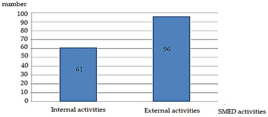
Figure 8.
The number of internal and external activities performed during the changeover before implementing the SMED method. Source: own study.
The SMED method is a team reduction in the machine changeover time, which allows for the division of the changeover activities into internal and external. SMED enables one to implement a continuous flow of products without compromising performances or waiting times. Such activities improve the quantitative and qualitative indicators of customer service. A detailed analysis of times allows for the elimination of external activities, the replacement of some internal activities with external ones, and the gradual reduction in the duration of other internal activities. The analysis of changeovers using the SMED method indicates activities whose durations significantly affect the extension of the machining process, thus being the cause of waste. The duration of changeover is an element determining the flexibility of the production process, and properly organized activities and designed flows at the workplace allow for its reduction. In the case under analysis, the separation of external activities and their improvements make it possible to shorten the time of setting up and calibrating the machine, thus leading to an increase in operational efficiency and the production of a larger number of production batches.
The Gantt chart shows the sequence of changeovers carried out by operators (Figure 9). The beginning of the abscissa is our start of retooling. The operators start the procedure simultaneously, when the last good piece of the old reference is packed. The total changeover time is 489.7 h, including the production of the first piece in 42 s. The chart shows especially long operator idle times between the first piece produced and the next. This analysis makes it possible to determine the bottlenecks for individual operators in most cases of redundancy, to optimize the idle times between the execution of the first piece and the next one by an average of 230 s., and to optimize the idle time between the execution of the first piece and the next one by an average of 230 s.
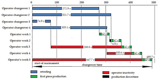
Figure 9.
Gantt chart showing the sequence of changeovers performed by operators before the changeover time reduction. Source: own study.
4.2. Design and Implementation of a New Changeover Process
Based on the observations, a detailed description of the activities performed by the operators along with their durations was developed, based on measurements during three changeovers.
Operator 1 worked at stations MO10 and MO20. The sequence of operator 1’s activities included the manual assembly of lamp components at the MO10 station and then the transfer of the semi-finished product to the M020 station, where the automatic assembly process took place (Figure 10).
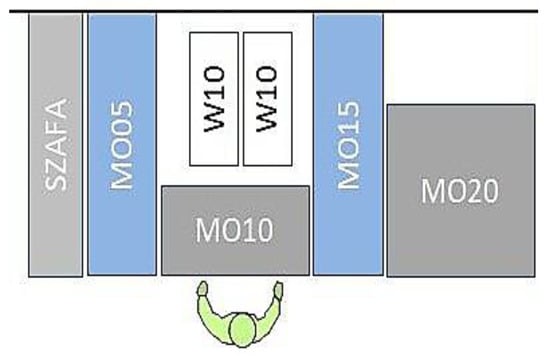
Figure 10.
Operator 1 and his workstations. Source: own study.
Operator 2 collected the semi-finished product after the MO20 work cycle was completed and continued to work on MO30 and MO40. At the MO30 station, the semi-finished product was manually retrofitted, and then automatic assembly with a glow test took place at the M040 station (Figure 11).
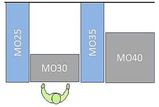
Figure 11.
Operator 2 and his workstations. Source: own study.
Operator 3 collected the semi-finished product after the MO40 work cycle, visually inspected it, and continued to work at the MO50 station. This was the gluing cell (Figure 12).
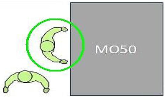
Figure 12.
Operator 3 and his workstations. Source: own study.
Operator 4 collected the semi-finished product after the work cycle of the MO50 station was completed, continued to work at the MO60 station, and added more subassemblies during manual assembly. After finishing work at the MO60 station, they placed the finished product at the MO70 station and started its work cycle, which included the control of the lighting and geometrical features of the lamp (Figure 13).
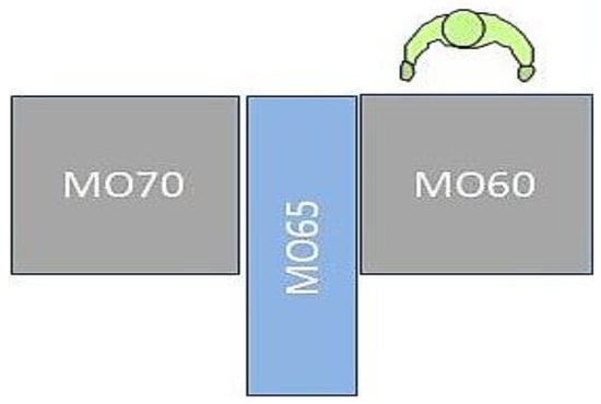
Figure 13.
Operator 4 and his workstations. Source: own study.
Operator 5 was an employee of an external company. They were responsible for the visual inspection of the lamp; their job was to check whether the product met all the requirements contained in the visual inspection standards and quality instructions. All compliant lamps were entered into the system by scanning the final label, which was stuck on the lamps after a positively completed test on the MO70 machine. This person did not participate in the changeover (Figure 14).
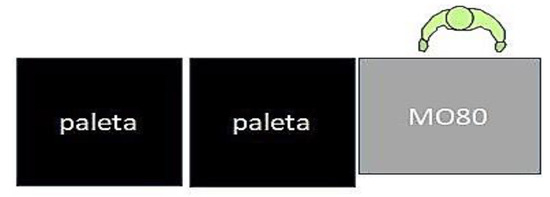
Figure 14.
Operator 5 and his workstations. Source: own study. The main defined wastes of operators include:
- -
- Human wainclude: of coordination of work, performing unnecessary tasks, waiting employees, using the wrong method of work;
- -
- Process waste: control that does not give permanent, long-term improvements, consequences of arbitrary decisions, waste resulting from the lack of standardization, consequences of uneven (smooth) flows of materials and information between workstations, waste related to the occurrence of errors and mistakes;
- -
- Information waste: waste due to lack of information, creating unnecessary, irrelevant information;
- -
- Waste of property: mismatch of resources with the work schedule, unnecessary movement of resources and information, materials related to the implementation of processes office administration that will not be used or are kept for too long;
- -
- Waste managerial: lack of proper organizational discipline, consequences of employees not identifying with their tasks and roles.
As part of the research, a detailed record of the operators’ workflow was developed for the innovative developed model of the changeover process. The analysis contained a detailed description of the activities performed by the operators along with their durations, developed on the basis of measurements during three performed changeovers. Measurements were made using a stopwatch and included an accurate, real-time course of activities. In this way, operators tested a new mechanism for introducing improvements, on the basis of which further modifications will be introduced. The analysis of the changeover process after the changes took into account all the operators’ activities, specifying their durations. According to the SMED methodology, activities were divided into internal and external. The total times of the operators’ activities are presented in Table 2. During the changeover, a total of 157 activities were performed—including 61 internal and 96 external. The path of the operator’s movement is shown in the Spaghetti diagram in Figure 15.

Table 2.
Analysis of the sequence of actions performed by operator 1 during the changeover of the MO10 and MO20 assembly stations after the changes.
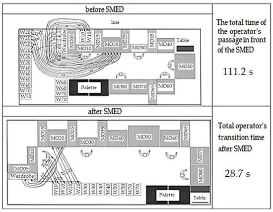
Figure 15.
Spaghetti diagram showing how operator 1 moves during the changeover of the MO10 and MO20 stations before and after the implementation of the SMED method. Source: own study.
The Spaghetti Analyses presented in Figure 15, Figure 16, Figure 17 and Figure 18 show the path of individual operators 1–4 and the activities performed at their workplace, but it can also be helpful in identifying the flow of components and semi-finished products. On the basis of these charts, the following can be made: shortening of the paths along which the material moves (choosing the shortest route), relocation of workstations (if the material is moved back and forth), frequency of movements between individual workstations, elimination of unnecessary activities (primarily bringing, packing unpacking, moving empty containers, etc.), batch sizes of production and transport batches, relief of the most frequently used intersections and transport paths, and improving internal transport and MUDY identifications.
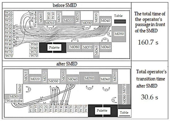
Figure 16.
Spaghetti diagram showing how operator 2 moves during the changeover of the MO30 and MO40 stations before and after the implementation of the SMED method. Source: own study.
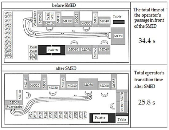
Figure 17.
Spaghetti diagram showing how operator 3 moves during the changeover of the MO30 and MO40 stations before and after the implementation of the SMED method. Source: own study.
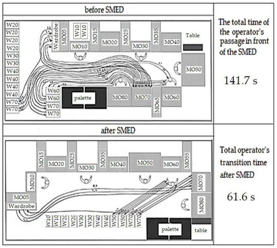
Figure 18.
Spaghetti diagram showing how operator 4 moves during the changeover of the MO30 and MO40 stations before and after the implementation of the SMED method. Source: own study.
A similar analysis was also performed for the remaining four operators. For operator 2, the summary analysis of the sequence of activities during the changeover of the MO30 and MO40 assembly stations is: execution time, 125.7 s; internal activities, 73.5 s; and external activities, 52.2 s. A Spaghetti chart showing the way operator 2 moves before the implementation SMED methods are shown in Figure 16.
For operator 3, the summary analysis of the sequence of activities during the changeover of the MO50 assembly station is: execution time, 66.3 s; internal activities, 30 s; and external activities, 36.6 s, Figure 17.
For operator 4, the summary analysis of the sequence of activities during the changeover of the MO60 and MO70 assembly stations is: execution time, 156.3 s; internal activities, 72 s; and external activities, 84.3 s. Spaghetti diagram showing the way operator 4 moves before implementing the SMED method shown in Figure 18.
The analysis of the changeover process after the changes took into account all the operators’ activities, specifying their durations. According to the SMED methodology, activities were divided into internal and external. The total time of operators’ activities after modernization amounted to 473.4 s, including internal activities performed in 248.9 s and external activities in 224.5 s. During the changeover, a total of 157 activities were performed—including 61 internal and 96 external. The Gantt chart shows the new sequence of changeovers performed by operators after applying SMED. Each of the operators starts the changeover of the stations where they work when they finish production. As a result of the changes made, this time was shortened to 198.3 s, which means that the changeover time was shortened by 291.4 s (Figure 19).
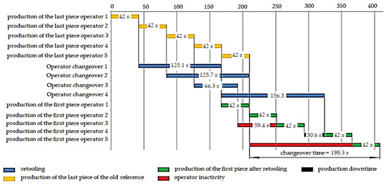
Figure 19.
Gantt chart showing the sequence of changeovers performed by operators after reduction in changeover time. Source: own study.
The analysis of the data presented in the diagram above concerns the time of four operators working individually on their tasks as part of a joint production operation. On the basis of optimization activities and calculated working times at individual stages, information is graphically presented for each operator, and how much time they have to perform their tasks, so as not to delay the work of the next operator who has his own time slot. These activities eliminate time losses and ensure effective production processes. Additional information is used to identify how the tasks of individual operators are connected to each other and to whom they are assigned, allowing one to determine the exact time of work in a given position. In the future, the analysis of this data may lead to the improvement of human resources management. It should be emphasized that there are still transport reserves in the subsystem for complex production capacity. When analyzing the device status diagram, attention was paid to the occurring micro-downtimes of the transport devices. They found their reflection in several-minute downtimes of the production unit, the elimination of which would allow for the increase of production volume. This could be performed by changing the stopping place of the trolleys transporting spare parts, without the need to integrate them into the production technology. Currently, the transport trolleys are waiting in the tool room next to the assembly line. When it is necessary to change machines, e.g., due to unplanned downtime, they must travel the entire length of the production hall, collect the appropriate type and grade of the spare part, and deliver it to the production line. This causes several-minute breaks in the operation of the technological line. If they were moved closer to the production line assembly, it would be much shorter travel time. A simulation of the behavior of the transport system was carried out for the changed location of the transport trolley station, the diagram of which is shown in Figure 20.
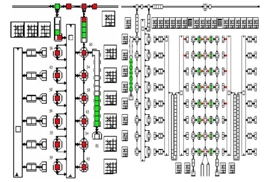
Figure 20.
The degree of utilization of production and transport equipment of the finishing unit, %.  system occupancy rate
  — no blocking system. Source: own study.
 system occupancy rate
  — no blocking system. Source: own study.
As a result of the simulation, it was found that the load on the production unit was 97%. The percentage occupancy also increased for trucks transporting spare parts. Comparing the simulation values without taking into account the time for delivery of tools, one could notice an improvement in the use of the effective working time of the production unit from the initial 63.4% to 84.7%.
Based on the obtained test results, an analysis of the effectiveness of the measures taken to reduce the changeover time was carried out. The use of the SMED methodology contributed to a significant reduction in changeover time—by as much as 291.4 s. The burden on operators was significantly reduced—the total time and number of operations performed by them (both internal and external) was reduced. The paths taken by the operators were also shortened by simple procedures, such as changing the layout of the lines and modifying the tool trolleys used for retooling and the tool locking systems at the stations.
4.3. Economic Analysis
The use of the SMED method eliminated redundant activities and shortened the operation time and the number of employee shifts to two, which resulted in significant cash savings. Below is the calculation of the profits achieved using the SMED methodology and the 375 basic assumptions used in it:
where
Z = (Tz· Lzr· Lp· L·C)/T [EUR]
Z—profit, EUR;
Tz—saving time using the SMED methodology, s;
Lzr—number of production shifts working on the line during the year;
Lp—number of rearming during a shift;
L—number of years of project duration;
T—line takt time, s;
C—price of one lamp, EUR;
Tz = 291.4 s;
Lzr = 1000;
Lp = 1;
L = 4;
T = 42 s;
C = 1000 EUR.
With idealized assumptions:
- -
- changeover takes place under ideal conditions included in the standards;
- -
- line working at full capacity;
- -
- failure-free machines;
- -
- all components compliant and available on time;
- -
- fixed, maximum customer orders.
The plant can gain up to EUR 5,871,407.11 with the reorganization of the changeover carried out in accordance with the SMED methodology. After the implementation of corrective actions in the form of system modifications, changeover trolleys, elimination of elements blocking tools requiring the use of keys and reorganization of the operators’ work order, it is possible to save 291.4 s during one changeover, during which six lamps can be produced. The simulation of the savings obtained over 5 years by implementing the described method is EUR 5,871,407.11 with maximum customer orders and the line operating at full capacity. The funds saved can be used for new research and innovations in the field of increasing the use of recycling, optimization of the life cycle, or the implementation of the closed loop and the principle of extended producer responsibility (EPR) in relation to this category of products. A properly implemented SMED method increases the availability of production equipment, which means that the OEE indicator shows an increase in the production efficiency of the analyzed machine. The obtained results confirm the legitimacy of the conducted research, being the basis for considering the introduction of process changes in the field of other spare parts and components of vehicles.
5. Conclusions
The success of manufacturers in the automotive industry depends, to a large extent, on whether the products offered are in line with current trends, requirements, and expectations of customers. The best examples of this are ecological standards, which have become increasingly important in recent years. The automotive industry must be prepared for the long-term challenge of minimizing the impact of the automotive industry on the natural environment [51]. At the first stage, it included a change in propulsion technologies, a reduction in the consumption of individual raw materials, and lower greenhouse gas emissions into the atmosphere. The next stage will be significant changes in the production of vehicles and spare parts, e.g., in the process of their final assembly. The very idea of a circular economy assumes maximizing the use of resources, materials, and products while minimizing waste or preparing it for reuse. The first step towards the implementation of a circular economy is the development of modern assembly lines that are effective—whether in terms of materials or energy—to increase production efficiency while minimizing costs.
The conducted research allowed to draw the following conclusions:
- The original design of the assembly line layout was non-functional, with flaws that made work difficult and lost time. Noticeable disadvantages included narrow passages between stations and poorly located places for storing tools and trolleys for changeovers. The trolleys were positioned on the left side of the production line, well away from the operator stations. In the case of the operator in the first station, the place for the tool trolleys was far behind the workstation. Employees interfered with each other while collecting carts with tools for changeover, blocking the way of others on the route leading to and from the station.
- The design of the bogies was another important factor contributing to longer changeover times. Some of them were used for retooling the lower tool and some for the upper tool. There were no trolleys that would combine these two functions at the same time. Merged carts shortened changeover times of automatic stations; operators could carry two tools at the same time.
- Screws were used to fasten the tools in the stations. Screwing in and out of the screws required a few or a dozen or so turns of the key and was preceded by finding and bringing appropriate keys from the tool cabinet. In order to reduce the time spent going to the cabinet to collect keys and the time spent on unscrewing screws, new latches were used, which were quick to use and did not require the use of any auxiliary devices.
- During the observations, it turned out that the first concept did not take into account the changeover time and the operators starting the changeover simultaneously when creating the layout, when the last good piece of the old reference was packed. Starting the changeover of the station by each operator at the moment when they finished their work at the station significantly reduced the changeover time.
- In the original concept of organizing the changeover on the line, its time using the SMED methodology was shortened to 198.3 s. This new changeover lasted 291.4 s shorter. The time used should have been spent on production for a line operating with a takt of 42 s; this was enough time to produce six full lamps. Implementation of corrective actions resulted in a reduction in the total time used by operators for changeover from 899.4 s to 473.4 s. The time of performing internal activities during changeover was significantly reduced, which was 368.4 s before and 248.9 s after the transformation. Furthermore, the times of external activities were from 531.3 s to 224.5 s. Additional benefits resulting from the introduction of the SMED method included the reduction in the number of external and internal activities. The number of internal activities was reduced from 61 to 43 and external activities from 96 to 63.
- The list of string charts (Spaghetti) accurately depicted how many operators passed on the assembly line were eliminated and what time savings this brought. In total, 27 transitions were eliminated. The movement times of the operators on the line were reduced: the first gained 8 s, the second 130.1 s, the third 8.6 s, and the fourth 80.1 s. These results were achieved thanks to simple solutions: a new design of the assembly line with a new, functional arrangement of stations and trolleys.
This article analyzed the retooling of the assembly line in relation to one selected spare part. Certainly, much more extensive analyses will be needed in the near future, covering a larger number of spare parts and vehicle components in particular. In addition, further research on this topic should focus on aspects related to the analysis of changes in the field of new technological and production solutions implemented in several key areas, such as designing new vehicle models using the same components and spare parts in this process. Another important element of further research in this matter will also be a cost analysis of the implementation of technologies based on the ideas of life cycle optimization, closed circuit, and the principle of extended producer responsibility (EPR), not only to selected elements of the vehicle, as it has been thus far, i.e., e.g., battery drive units [40], but also other spare parts or even complete subassemblies.
Summing up the presented considerations on the project of an innovative model of reducing machine changeover times in order to improve production efficiency in the automotive industry as a way to a circular economy, they certainly do not fully exhaust the essence of the issue. They are only a fragment and, at the same time, an encouragement for further research in this matter. Therefore, such analyses will be the subject of future work aimed at defining and identifying key factors for the implementation of such an ambitious plan for the automotive industry, in which environmental protection and rope production are not mutually exclusive.
SMED is an approach that usually requires considerable time commitment from the company’s employees, which is sometimes treated as a significant disadvantage of this method. However, spending time on improvement activities is necessary to achieve significant results, as evidenced by the countless examples of SMED implementations in various industries. Therefore, models should be built using artificial intelligence methods. The use of these methods would enable even better results and the development of more efficient models. To this end, a hybrid approach should be taken into account, combining elements of effective management tools and artificial intelligence based on expert knowledge models.
Author Contributions
Conceptualization, M.N. and W.L.; methodology, M.N. and W.L.; software, M.N. and W.L.; validation, M.N. and W.L.; formal analysis, M.N., W.L., H.H.C., and M.B.; investigation, M.N. and W.L.; resources, M.N., W.L., H.H.C., and M.B.; data curation, M.N. and W.L.; writing—original draft preparation, M.N. and W.L.; writing—review and editing, M.N. and W.L.; visualization, M.N.; supervision, W.L.; project administration, M.N. and W.L. funding acquisition, M.N. and W.L. All authors have read and agreed to the published version of the manuscript.
Funding
This research received no external funding.
Institutional Review Board Statement
Not applicable.
Informed Consent Statement
Not applicable.
Data Availability Statement
Not applicable.
Conflicts of Interest
The author declares no conflict of interest.
References
- Abinaya Ishwarya, G.K.; Rajkumar, D. Analysis of ergonomic risk factors in construction industry. Mater. Today Proc. 2020, 37, 2415–2418. [Google Scholar] [CrossRef]
- Santos, A.C.O.; da Silva, C.E.S.; Braga, R.A.D.S.; Corrêa, J.É.; de Almeida, F.A. Customer value in lean product development: Conceptual model for incremental innovations. Syst. Eng. 2020, 23, 281–293. [Google Scholar] [CrossRef]
- Afonso, T.; Alves, A.C.; Carneiro, P. Lean thinking, logistic and ergonomics: Synergetic triad to prepare shop floor work systems to face pandemic situations. Int. J. Glob. Bus. Compet. 2021, 16, 62–76. [Google Scholar] [CrossRef]
- Ohno, T.; Bodek, N. Toyota Production System: Beyond Large-Scale Production; Productivity Press: New York, NY, USA, 2019. [Google Scholar]
- AlManei, M.; Salonitis, K.; Xu, Y. Lean implementation frameworks: The challenges for SMEs. In Procedia CIRP, Manufacturing Systems 4.0–Proceedings of the 50th CIRP Conference on Manufacturing Systems; Elsevier: Amsterdam, The Netherlands, 2017; Volume 63, pp. 750–755. [Google Scholar] [CrossRef]
- Danese, P.; Manfè, V.; Romano, P. A systematic literature review on recent lean research: State-of-the-art and future directions. Int. J. Manag. Rev. 2018, 20, 579–605. [Google Scholar] [CrossRef]
- Baysan, S.; Kabadurmus, O.; Cevikcan, E.; Satoglu, S.I.; Durmusoglu, M.B. A simulation-based methodology for the analysis of the effect of lean tools on energy efficiency: An application in power distribution industry. J. Clean. Prod. 2019, 211, 895–908. [Google Scholar] [CrossRef]
- Melin, M.; Barth, H. Lean in Swedish agriculture: Strategic and operational perspectives. Prod. Plan. Control 2018, 29, 845–855. [Google Scholar] [CrossRef]
- Boran, S.; Ekincioglu, C. A novel integrated SMED approach for reducing setup time. Int. J. Adv. Manuf. Technol. 2017, 92, 3941–3951. [Google Scholar] [CrossRef]
- Doevendans, H.J.; Grigg, N.P.; Goodyer, J. Exploring Lean deployment in New Zealand apple pack-houses. Meas. Bus. Excell. 2015, 19, 46–60. [Google Scholar] [CrossRef]
- Botti, L.; Mora, C.; Regattieri, A. Improving ergonomics in the meat industry: A case study of an Italian ham processing company. IFAC-pap. In Proceedings of the 15th IFAC Symposium on Information Control Problems in Manufacturing, Ottawa, Canada, 11–13 May 2015; Volume 48, pp. 598–603. [Google Scholar] [CrossRef]
- Aoki, R.; Katayama, H. Heijunka Operation Management of Agri-Products Manufacturing by Yield Improvement and Cropping Policy. In International Conference on Management Science and Engineering Management; Springer: Berlin/Heidelberg, Germany, 2017; pp. 1407–1416. [Google Scholar]
- Brito, M.; Ramos, A.L.; Carneiro, P.; Gonçalves, M.A. Combining SMED methodology and ergonomics for reduction of setup in a turning production area. In Proceedings of the Manufacturing Engineering Society International Conference 2017, MESIC 2017, Vigo, Spain, 28–30 June 2017; Volume 13, pp. 1112–1119. [Google Scholar] [CrossRef]
- Da Silva, I.B.; Godinho Filho, M. Single-minute exchange of die (SMED): A state-of-the-art literature review. Int. J. Adv. Manuf. Technol. 2019, 102, 4289–4307. [Google Scholar] [CrossRef]
- Wurster, S. Creating a Circular Economy in the Automotive Industry: The Contribution of Combining Crowdsourcing and Delphi Research. Sustainability 2021, 13, 6762. [Google Scholar] [CrossRef]
- Brito, M.; Vale, M.; Leao, J.; Ferreira, L.P.; Silva, F.J.G.; Gonçalves, M.A. Lean and Ergonomics decision support tool assessment in a plastic packaging company. Procedia Manuf. 2020, 51, 613–619. [Google Scholar] [CrossRef]
- Shahin, M.; Chen, F.F.; Bouzary, H.; Krishnaiyer, K. Integration of Lean practices and Industry 4.0 technologies: Smart manufacturing for next-generation enterprises. Int. J. Adv. Manuf. Technol. 2020, 107, 2927–2936. [Google Scholar] [CrossRef]
- Castellucci, H.I.; Viviani, C.; Hernandez, P.; Bravo, G.; Martínez, M.; Ibacache, J.; Bartsch, A. Developing countries and the use of ISO standard 11228-3 for risk management of work-related musculoskeletal disorders of the upper limbs (WRMSDs-ULs): The case of Chile. Appl. Ergon. 2021, 96, 103483. [Google Scholar] [CrossRef]
- Jamwal, A.; Agrawal, R.; Sharma, M.; Giallanza, A. Industry 4.0 technologies for manufacturing sustainability: A systematic review and future research directions. Appl. Sci. 2021, 11, 5725. [Google Scholar] [CrossRef]
- Pérez-Pucheta, C.E.; Olivares-Benitez, E.; Minor-Popocatl, H.; Pacheco-García, P.F.; Pérez-Pucheta, M.F. Implementation of Lean Manufacturing to Reduce the Delivery Time of a Replacement Part to Dealers: A Case Study. Appl. Sci. 2019, 9, 3932. [Google Scholar] [CrossRef]
- Milios, L.; Matsumoto, M. . Consumer Perception of Remanufactured Automotive Parts and Policy Implications for Transitioning to a Circular Economy in Sweden. Sustainability 2019, 11, 6264. [Google Scholar] [CrossRef]
- Cirjaliu, B.; Draghici, A. Ergonomic issues in lean manufacturing. In Proceedings of the 13th International Symposium in Management: Management During and After the Economic Crisis, Amsterdam, The Netherlands, 18–20 November 2016; Volume 221, pp. 105–110. [Google Scholar] [CrossRef]
- Lermen, F.H.; Echeveste, M.E.; Peralta, C.B.; Sonego, M.; Marcon, A. A framework for selecting lean practices in sustainable product development: The case study of a Brazilian agroindustry. J. Clean. Prod. 2018, 191, 261–272. [Google Scholar] [CrossRef]
- Crema, M.; Verbano, C. Identification and development of lean and safety projects. Saf. Sci. 2016, 89, 319–337. [Google Scholar] [CrossRef]
- De Steur, H.; Wesana, J.; Dora, M.; Pearce, D.; Gellynck, X. Applying Value Stream Mapping to reduce food losses and wastes in supply chains: A systematic review. Waste Manag. 2016, 58, 359–368. [Google Scholar] [CrossRef]
- Dombrowski, U.; Wullbrandt, J.; Reimer, A. Lean stress sensitization in learning factories. In Proceedings of the 7th conference on learning factories, CLF, Darmstadt, Germany, 4–5 April 2017; Volume 9, pp. 339–346. [Google Scholar] [CrossRef]
- Satolo, E.G.; Hiraga, L.E.D.M.; Zoccal, L.F.; Goes, G.A.; Lourenzani, W.L.; Perozini, P.H. Techniques and tools of lean production: Multiple case studies in brazilian agribusiness units. Gestão Produção 2020, 27, e3252. [Google Scholar] [CrossRef]
- Garre, P.; Nikhil Bharadwaj, V.V.S.; Shiva Shashank, P.; Harish, M.; Sai Dheeraj, M. Applying lean in aerospace manufacturing. Mater. Today Proc. 2017, 4, 8439–8446. [Google Scholar] [CrossRef]
- Omair, M.; Alkahtani, M.; Ayaz, K.; Hussain, G.; Buhl, J. Supply Chain Modelling of the Automobile Multi-Stage Production Considering Circular Economy by Waste Management Using Recycling and Reworking Operations. Sustainability 2022, 14, 15428. [Google Scholar] [CrossRef]
- Reis, L.V.; Kipper, L.M.; Velásquez, F.D.G.; Hofmann, N.; Frozza, R.; Ocampo, S.A.; Hernandez, C.A.T. A model for Lean and Green integration and monitoring for the coffee sector. Comput. Electron. Agric. 2018, 150, 62–73. [Google Scholar] [CrossRef]
- Karanikas, N.; Pazell, S.; Wright, A.; Crawford, E. The what, why and how of good work design: The perspective of the human factors and ergonomics society of Australia. In Advances in Ergonomics in Design, Lecture Notes in Networks and Systems; Rebelo, F., Ed.; Springer International Publishing: Cham, Switzerland, 2021; pp. 904–911. [Google Scholar] [CrossRef]
- Dey, B.K.; Sarkar, B.; Seok, H. Cost-effective smart autonomation policy for a hybrid manufacturing-remanufacturing. Comput. Ind. Eng. 2021, 162, 107758. [Google Scholar] [CrossRef]
- Lazai, M.; Santos, L.C.P.; Grossi Chamie, N.R.; Pierezan, R.; Loures, E.R.; Santos, E.P.; Costa, S.E.G.; Lima, E.P. Automated system gains in lean manufacturing improvement projects. Procedia Manuf. 2020, 51, 1340–1347. [Google Scholar] [CrossRef]
- Dey, B.K.; Pareek, S.; Tayyab, M.; Sarkar, B. Autonomation policy to control work-in-process inventory in a smart production system. Int. J. Prod. Res. 2021, 59, 1258–1280. [Google Scholar] [CrossRef]
- Mathew Alexander, L.; Saleeshya, P.G. Qualitative analysis of different lean assessment methods: A comprehensive review of applications. Mater. Today Proc. 2022, 58, 387–392. [Google Scholar] [CrossRef]
- Bhamu, J.; Sangwan, K.S. Lean manufacturing: Literature review and research issues. Int. J. Oper. Prod. Manag. 2014, 34, 876–940. [Google Scholar] [CrossRef]
- Thürer, M.; Tomašević, I.; Stevenson, M. On the meaning of ‘waste’: Review and definition. Prod. Plan. Control 2017, 28, 244–255. [Google Scholar] [CrossRef]
- Dave, Y.; Sohani, N. Single minute exchange of dies: Literature review. Int. J. Lean Think. 2012, 3, 27–37. [Google Scholar]
- McIntosh, R.; Culley, S.; Mileham, A.R.; Owen, G. A critical evaluation of Shingo’s’ SMED’ (Single Minute Exchange of Die) methodology. Int. J. Prod. Res. 2000, 38, 2377–2395. [Google Scholar] [CrossRef]
- Modoi, O.-C.; Mihai, F.-C. E-Waste and End-of-Life Vehicles Management and Circular Economy Initiatives in Romania. Energies 2022, 15, 1120. [Google Scholar] [CrossRef]
- Vinoth Kumar, H.; Annamalai, S.; Bagathsingh, N. Impact of lean implementation from the ergonomics view: A research article. Mater. Today Proc. 2020, 46, 9610–9612. [Google Scholar] [CrossRef]
- Yang, C.-M.; Chen, K.-S. An integrated contract manufacturer selection and product quality optimization methodology for the mechanical manufacturing industry. Expert Syst. Appl. 2021, 18, 115336. [Google Scholar] [CrossRef]
- Reklitis, P.; Sakas, D.P.; Trivellas, P.; Tsoulfas, G.T. Performance implications of aligning supply chain practices with competitive advantage: Empirical evidence from the agri-food sector. Sustainability 2021, 13, 8734. [Google Scholar] [CrossRef]
- Raicu, C.-C.; Seriţan, G.-C.; Enache, B.-A.; Stănculescu, M. Development Approach Model for Automotive Headlights with Mixed Delivery Methodologies over APQP Backbone. Appl. Sci. 2021, 11, 10581. [Google Scholar] [CrossRef]
- Parent-Lamarche, A.; Marchand, A.; Saade, S. How do work organization conditions affect job performance? The mediating role of workers’ well-being. J. Workplace Behav. Health 2021, 36, 48–76. [Google Scholar] [CrossRef]
- Shawcross, P.; Lyons, M.; Filingeri, V. The relationship between readiness to change pain-related exercise participation and perceived work function: A cross-sectional study of factory workers. BMC Musculoskelet. Disord. 2021, 22, 1–10. [Google Scholar] [CrossRef]
- Nallusamy, S.; Vijay, K.; Vivek, Y.; Kumar Prasad, U.; Suman, S.K. Implementation of total productive maintenance to enhance the overall equipment effectiveness in medium scale industries. Int. J. Mech. Prod. Eng. Res. Dev. 2018, 8, 1027–1038. [Google Scholar]
- Nallusamy, S.; Gautam, M. Enhancement of overall equipment effectiveness using total productive maintenance in a manufacturing industry. Int. J. Perform. Eng. 2017, 13, 173–188. [Google Scholar] [CrossRef]
- Rao, G.V.P.; Nallusamy, S.; Rajaram Narayanan, M. Augmentation of production level using different lean approaches in medium scale manufacturing industries. Int. J. Mech. Eng. Technol. 2017, 8, 360–372. [Google Scholar]
- Saravanan, V.; Nallusamy, S.; Balaji, K. Lead time reduction through execution of lean tool for productivity enhancement in small scale industries. Int. J. Engg. Res. Afr. 2018, 34, 116–127. [Google Scholar] [CrossRef]
- Mikosch, N.; Dettmer, T.; Plaga, B.; Gernuks, M.; Finkbeiner, M. Relevance of Impact Categories and Applicability of Life Cycle Impact Assessment Methods from an Automotive Industry Perspective. Sustainability 2022, 14, 8837. [Google Scholar] [CrossRef]
Disclaimer/Publisher’s Note: The statements, opinions and data contained in all publications are solely those of the individual author(s) and contributor(s) and not of MDPI and/or the editor(s). MDPI and/or the editor(s) disclaim responsibility for any injury to people or property resulting from any ideas, methods, instructions or products referred to in the content. |
© 2023 by the authors. Licensee MDPI, Basel, Switzerland. This article is an open access article distributed under the terms and conditions of the Creative Commons Attribution (CC BY) license (https://creativecommons.org/licenses/by/4.0/).