Article

Fault-Tolerant Control Strategy for Hall Sensors in BLDC Motor Drive for Electric Vehicle Applications

by
Mariem Ahmed Baba
1,*,
Mohamed Naoui
2,* and
Mohamed Cherkaoui
1
1
Engineering for Smart and Sustainable Systems Research Center, Mohammadia School of Engineers, Mohammed V University in Rabat, Rabat 10000, Morocco
2
Research Unit of Energy Processes Environment and Electrical Systems, National Engineering School of Gabes, University of Gabés, Gabés 6029, Tunisia
*
Authors to whom correspondence should be addressed.
Sustainability 2023, 15(13), 10430; https://doi.org/10.3390/su151310430
Submission received: 3 June 2023 / Revised: 27 June 2023 / Accepted: 29 June 2023 / Published: 2 July 2023
(This article belongs to the Special Issue Modern Control Techniques for Electrical Drives)

Abstract

:
The adoption of the brushless DC motor in the electric drive vehicle industry continues to grow due to its robustness and ability to meet torque–speed requirements. This work presents the implementation of a fault-tolerant control (FTC) for a BLDC motor designed for electric vehicles. This paper focuses on studying the defect in the Ha sensor and its signal reconstruction, assuming possible cases, but the same principle is applied to the other two sensors (Hb and Hc ). In this case, the fault diagnosis allows for the correction and reconstruction of the signal in order to compel the system to work despite the presence of a fault. Indeed, several robust control systems are used within the work to regulate the speed of the motor properly, such as control via fuzzy logic and control via a neural network. This paper presents three BLDC control configurations for EVs, PID, fuzzy logic (FL), and an artificial neural network (ANN), discusses the pros and cons, and develops corresponding mathematical models to enhance a fault-tolerant control strategy which is analyzed and studied using MATLAB-based simulations (by discussing the two cases, the steady state and the transient state), allowing for a novel design based on the analytical models developed. The results obtained from the simulation of this system improved the speed controlled by the neural network compared to the fuzzy logic controller. At the same time, the sensor failure had no effect on the system’s operation due to the efficiency of the FTC control.

1. Introduction

Permanent magnet synchronous motors (PMSMs) are highly regarded as electrical machines with permanent magnets placed on the rotor surfaces; the inner one is equipped with permanent magnets placed inside the rotor. The brushless DC (BLDC) motor is considered a category of permanent magnet synchronous motors. In fact, these two engines have similar architectures but with several differences [1]. Moreover, the BLDC motor can be distinguished from the PMSM motor via the form of electromotive force (EMF) because the EMF of a BLDC motor is in trapezoidal shape, while the EMF of a PMSM is in a sinusoidal form. The broad diffusion of BLDC motors into the industrial sector is explained by their high levels of efficiency, convenient sizes, simple architectures, and high energy densities [2]. Among the fields using BLDC motors, we find electric vehicles (EV) thanks to their high levels of performance and offer of simple powertrain mechanisms. The propulsion of electric motor vehicles began to be exploited in the 19th century [3], demonstrating better performance with respect to their ease of use in addition to their role in preserving the environment at that time. According to a comparative study between electric motors used in EVs carried out by M. Yildirim, M. Polat, and H. Kürüm [4], brushless and induction motors are the most commonly adopted motors in EVs due to their satisfactory characteristics, including their high levels of efficiency and high power densities. BLDC engines have ensured innovative EV models that combine exemplary performance and environmental friendliness [5]. Several types of robust control have been proposed in the literature to control the speed of a BLDC motor, such as fuzzy logic, adaptive control, and neural network control. As PI and PID controllers provide limited results in some applications, researchers have proposed a fuzzy logic controller to limit the disturbances and achieve more stable results [6]. Another control strategy combining PID and fuzzy logic controllers is implemented in [7].
On the other hand, O.D. Ramírez-Cárdenas and F. Trujillo Romero [8] used both PID and neural network controllers in the sensorless speed control of a BLDC motor. The results of this work proved the effectiveness of neural network control. Indeed, several papers have discussed the hybrid strategy of using different controllers to achieve the desired results. For example, in [9], the authors chose to apply a fuzzy PID control system of a neural network to a BLDC motor to reduce the influence of the switching process of the studied system. Failures are always expected during the operation of real systems despite all the protection procedures used. Thus, fault-tolerant control (FTC) is very important to ensure the continuity of operation of the targeted model. Unlike self-commutating motors, the BLDC motor requires an electronic commutation system and knowledge of the rotor position at different times. Therefore, the main methods used to detect the rotor position are the use of sensors (the most common of which is the Hall effect sensor) and the sensorless mode [10]. This work adopts the sensor method by introducing a Hall effect sensor. When studying the defects of the sensors, it is essential to estimate the angle of the rotor of the studied motor. Indeed, the faults generally studied in BLDC motors are divided into electrical, mechanical, and magnetic [11,12]. Concerning sensor faults, A. Mousmi, A. Abbou, and Y. El Houm [13] presented a fault detection strategy for a Hall effect sensor via considering binary circuits that deal only with the signals of the three implemented sensors. In the same context, Q. Zhang and M. Feng [14] proposed a fast fault detection (FFD) technique for a BLDC motor that aimed to detect sensor faults and correct faulty signals not only quickly but also simultaneously. Furthermore, [15] proposed an improved fault diagnosis method which consisted of reformulating Hall sensor (HS) signals quickly and without observers. To achieve on an economical FTC, Y. Zhao, W. Huang, and J. Yang [16] proposed a fault diagnosis technique for a permanent magnet synchronous motor. This method determines each type of fault based on the number of faulty sensors.
Recent papers, however, have discussed other diagnostic techniques. K. Gayatri Sarman, T. Madhu, and A. Mallikharjuna Prasad [17] proposed a fuzzy inference strategy supported by an advanced adaptive network (AANFIS) that consists of locating short and open circuit defects. Therefore, a concrete analysis is presented in [18] that aims to use the fault diagnosis process of a BLDC engine for three different fault cases. Several tools have been used to realize this study, like the ensemble empirical mode decomposition (EEMD) and the appropriate intrinsic mode function (IMF). The works mentioned above focus on the fault-tolerant control (FTC) principle for a BLDC motor. At the same time, other research studies deal with the FTC control of a BLDC motor designed for electric vehicles. The exploitation of this control increases the performance and safety of electric vehicles. Another study was presented by P.H. Kumar and V.T. Somasekhar [19], using a type of FTC control based on a BLDC motor drive system with multiple switches. This technique has the feature of self-configuration and according to the results obtained, it shows an adequate fault tolerance for both open and short circuits.
The structure of this work is organized into several sections after the introduction. Section 2 discusses the electrical traction system for an EV and the mathematical modeling of the BLDC motor. Section 3 defines the Hall effect sensor and describes the various types of faults associated with it. Section 4 studies the three adapted controllers, describing in detail the characteristics of each control system with their corresponding diagrams. The next section presents the results and discussion of the simulation and comparison of different control strategies. Finally, the conclusion offers some thoughts on the work provided.

2. Electrical Traction System Design and Mathematical Model

This section presents the modeling of a system comprising a three-phase BLDC motor, such as the trapezoidal back electromotive force (EMF) of a permanent magnet synchronous motor fed through a voltage inverter through the use of three Hall effect sensors [20]. To determine the six switching instants during the operation of a BLDC motor, it is necessary to first adopt one of the designed technologies which, in this work, are implemented using Hall effect sensors [6,21]. Table 1 provides the values of the output signals delivered in each case by the Hall effect sensors [22].
The equation of a BLDC motor is found by representing its two models: electrical and mechanical [23,24]. The electrical model of a BLDC motor is related to the basic voltage equations of the armature winding for a BLDCM and can be represented as follows:
{ V a = R I a + L ( d i a d t ) + e a V b = R I b + L ( d i b d t ) + e b V c = R I c + L ( d i c d t ) + e c
The vector of the voltages across the three phases according to Equation (1) can be represented in the following matrix form:
[ V a V b V c ] = [ R 0 0 0 R 0 0 0 R ] [ I a I b I c ] + d d t [ L a a L a b L a c L b a L b b L b c L c a L c b L c c ] [ i a i b i c ] + [ e a e b e c ] .  
The electromotive forces (EMFs) of each phase (a, b, c) have 120° phase angles and are given as:
{ e a = k e f ( θ ) ω e b = k e f ( θ 2 π 3 ) ω e c = k e f ( θ + 2 π 3 ) ω
where ke is the coefficient of the back EMF of one phase and ω is angular speed of the rotor.
The electrical angle of the rotor is given as:
θ = P 2 θ m
where θ m is the mechanical rotor angle.
P represents the number of pairs of poles.
For the mechanical model of the BLDC motor, the mechanical equation of motion is provided in the form below:
J d ω d t = T e B ω T r
The expression of the electromagnetic torque can be established from the following relationship:
T e = P e m ω
With
P e m = e a i a + e b i c + e c i c
P e m represents electromagnetic power.
Finally, the electromagnetic torque is provided by:
T e = e a i a + e b i b + e c i c ω
The simulation model, generated via MATLAB Simulink, is represented in Figure 1.

3. Ideal Hall Signal and Hall Sensor (HS) Fault Types

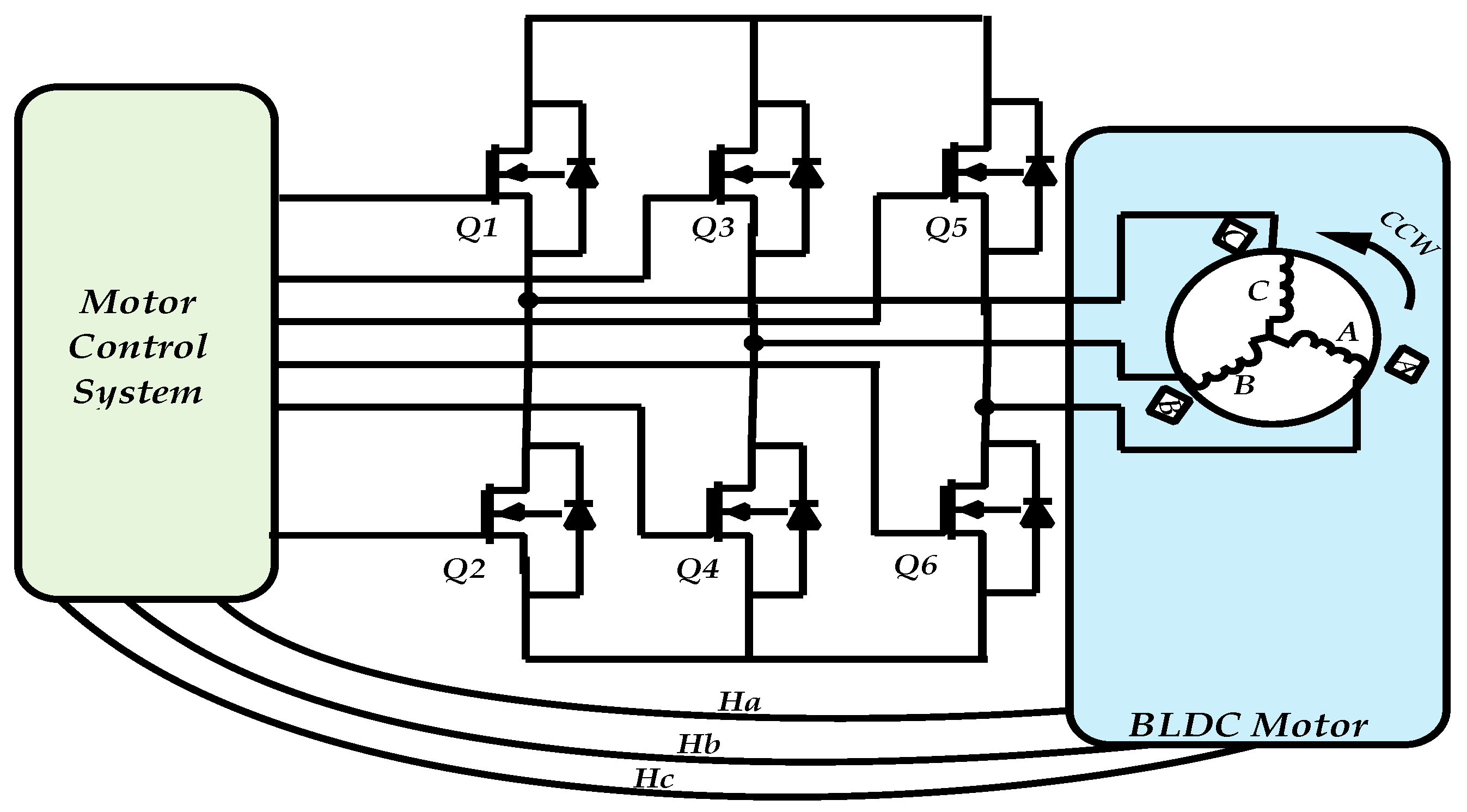
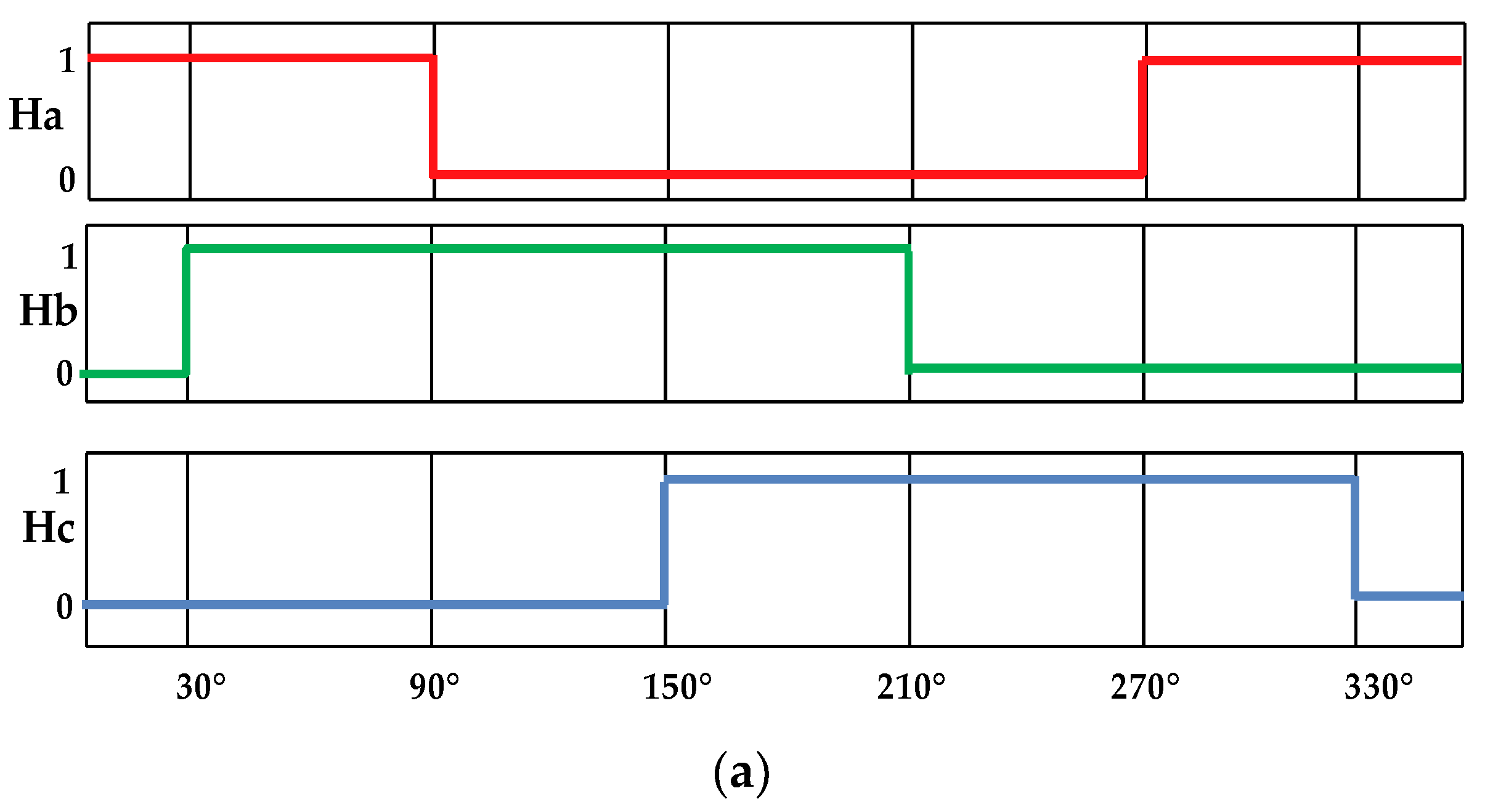
The BLDC motor is equipped with three Hall sensors, a voltage source inverter, and a motor control system [25]. The three Hall sensors, A, B, and C, are permanently attached to the stator. When the rotor is rotated to different places, the Hall sensors produce separate Hall signals, Ha, Hb, and Hc [26]. As indicated in Figure 2, the rotor locations are split into six sectors by a distinct Hall signal with a ( π 3 )   rad interval angle [27].
When the rotor moves from one sector to the next, an edge signal appears in the matching Hall signal. Without sacrificing generality, the Hi edge signal (i = a, b, c) is represented by Ei:
E i = { 1             d H i d t > 0 1             d H i d t < 0 0             d H i d t   =   0

3.1. Fault Detection

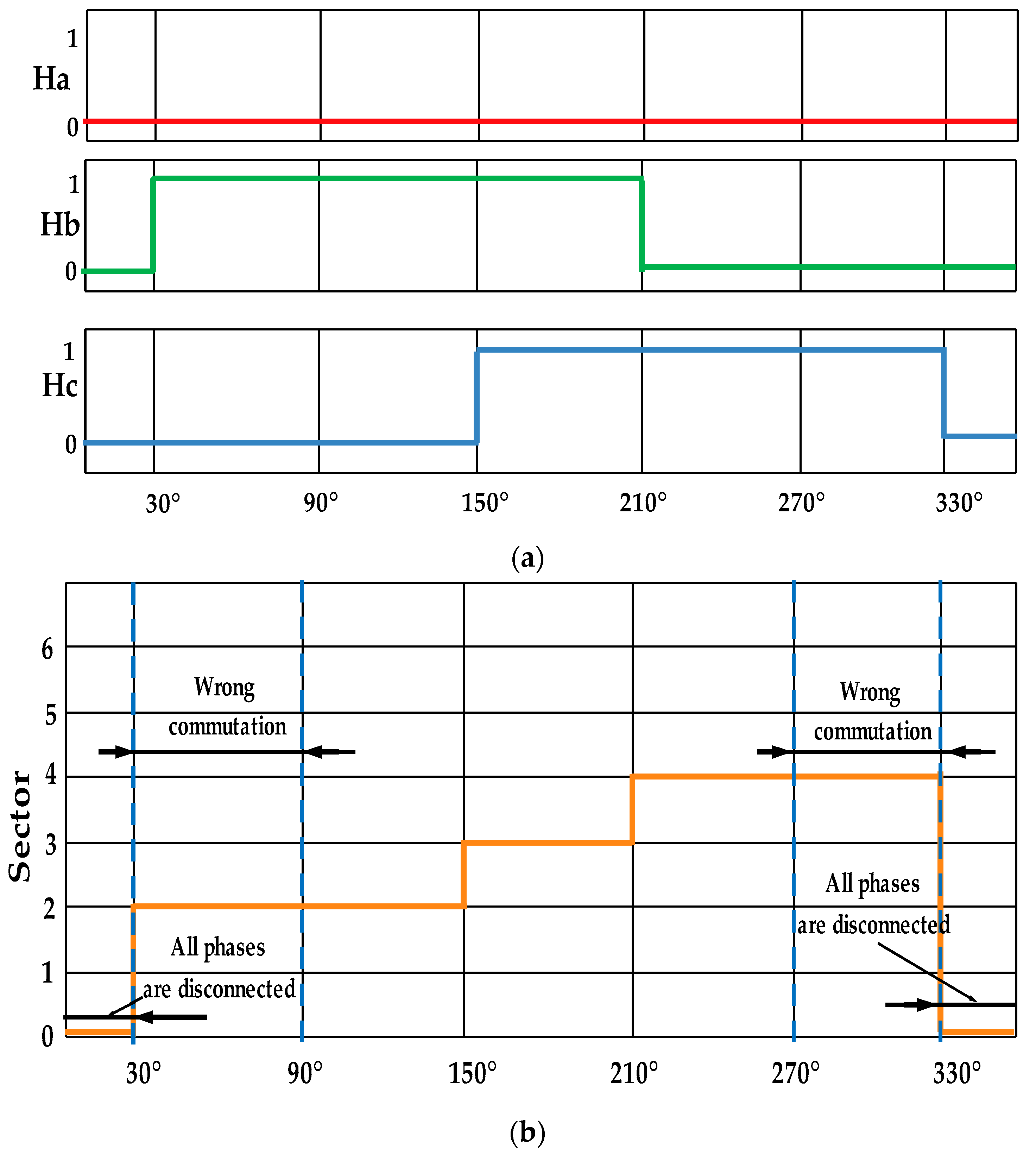
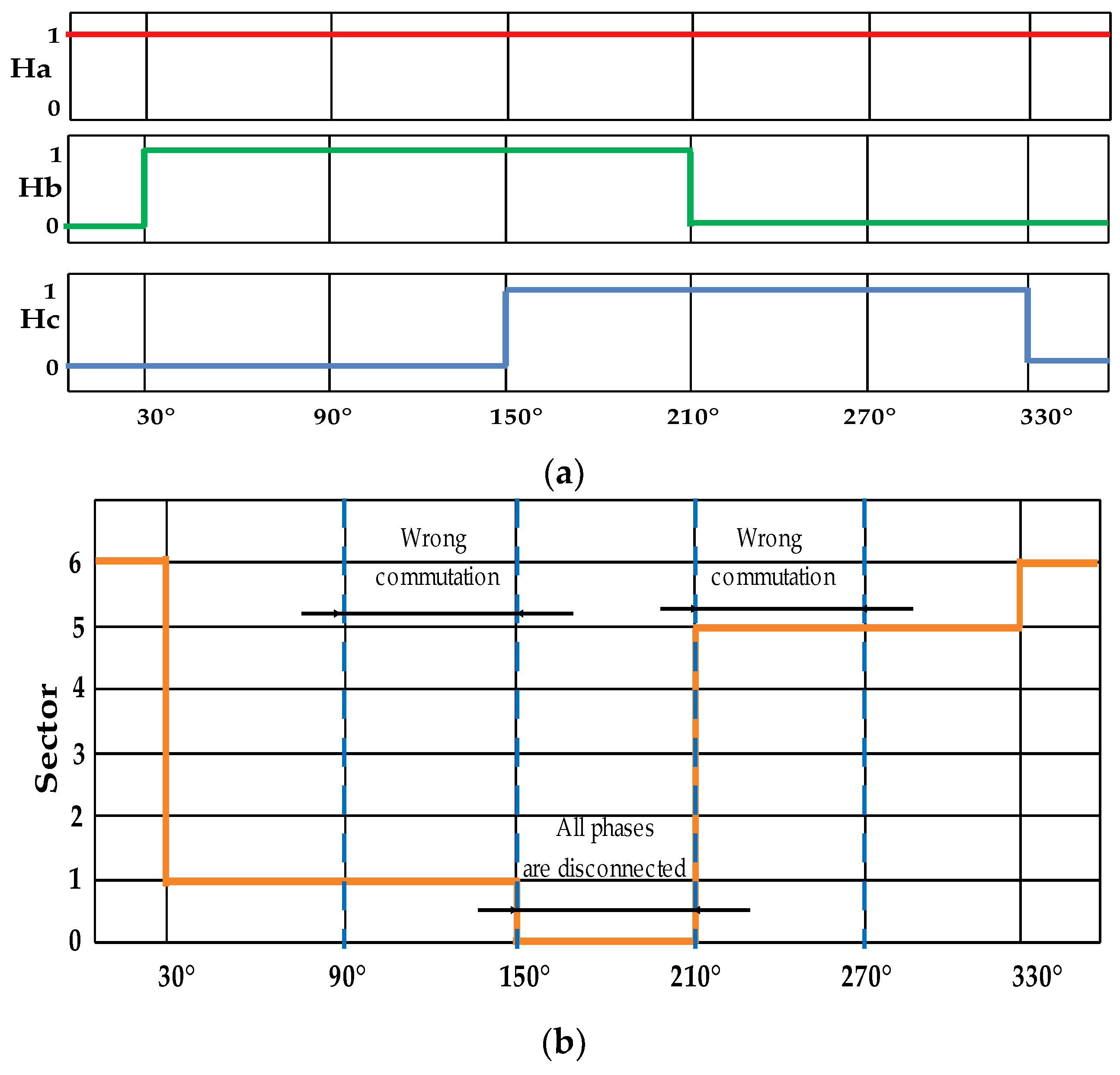
The three Hall effect sensor signals Hi (i = a, b, c) change state based on the rotor position during the typical operation of a BLDC motor. As a result, in a 360° electrical cycle, they generate six distinct sequences. Each sequence corresponds to a well-defined rotor-rotation-based phase current commutation [14]. Figure 3 and Table 2 show the phase current commutation for each sector in a counterclockwise rotation. If one of the sensors fails, the three signals, Habc. offer four sectors instead of three [28]. In two sectors, inappropriate commutations occur and no phase is energized in the third sector, in contrast to the customary operation control [13].
The nature of failure determines which sector’s control is jeopardized. Figure 4 and Figure 5 depict the altered sector sequence and the damaged commutation phases in both cases (a fault in sensor Ha). Table 3 shows the new commutations found using the conventional technique.

3.2. Proposed Fault Diagnosis Method

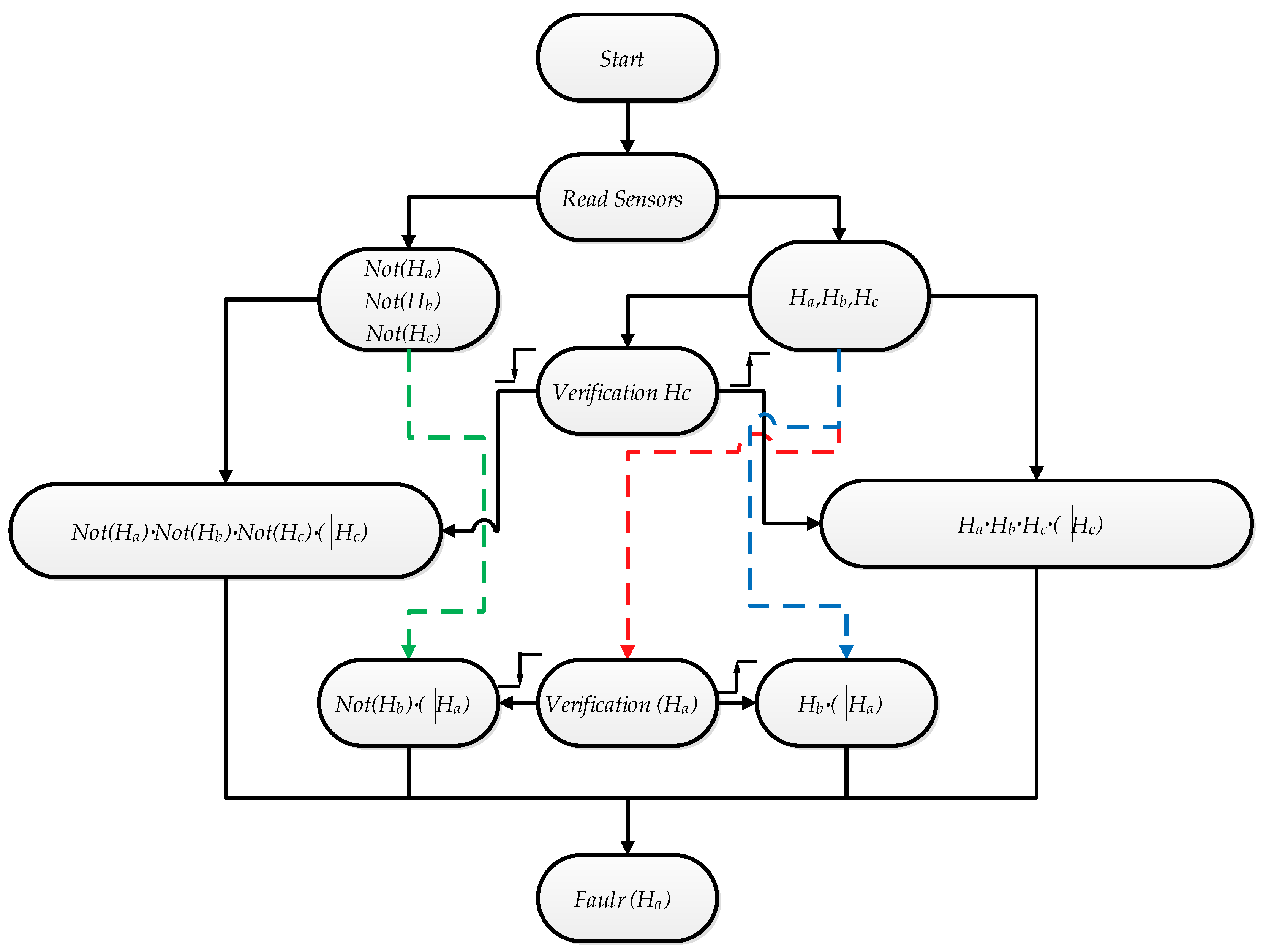
This paper proposes the use of binary circuits for defect detection based purely on the three Hall effect sensor signals [15], and it examines the defect detection circuit at the Ha sensor during counterclockwise rotor rotation without a loss of generality [29]. The many causes of sensor failure are summarized in seven instances based on the sector in which the failure occurs. These cases are provided in Table 4.
It should be observed that in the preceding four examples, the failures are discovered promptly [26].
As a result, the following combinational circuits, represented by Equation (10), require just three runs to memorize the three prior states of the Hall effect signals and may detect the various scenarios of fault occurrence at sensor Ha in a counterclockwise rotation:
F a c c w = ( H a ) · H b + ( H a ) · H b ¯ + H a · H b · H c ( H c ) + H a ¯ · H b ¯ · H c ¯ ( H c )
Figure 6 depicts the implementation of this function (Equation (10)). The same logic is used to detect defects in the sensors Hb and Hc and can be represented as follows:
F b c c w = ( H b ) · H c + ( H b ) · H c ¯ + H a · H b · H c ( H a ) + H a ¯ · H b ¯ · H c ¯ ( H a )
F c c c w = ( H c ) · H a + ( H c ) · H a ¯ + H a · H b · H c ( H b ) + H a ¯ · H b ¯ · H c ¯ ( H b )
The defect detection functions that follow the same reasoning in the case of clockwise rotation are as follows:
F c c c w = ( H c ) · H a + ( H c ) · H a ¯ + H a · H b · H c ( H b ) + H a ¯ · H b ¯ · H c ¯ ( H b )
F b c w = ( H b ) · H a + ( H b ) · H a ¯ + H a · H b · H c ( H c ) + H a ¯ · H b ¯ · H c ¯ ( H c )          
F c c w = ( H c ) · H b + ( H c ) · H b ¯ + H a · H b · H c ( H a ) + H a ¯ · H b ¯ · H c ¯ ( H a )  
It should be noted that faults in Ha are quickly noticed in the clockwise direction if they occur in sectors 1, 3, 4, or 6 but not in sectors 2 or 5.

3.3. Signal Reconstruction

In the case of a sensor failure, the table containing the different commutations of the current phase will not be considered because the data on the sector containing the rotor are inaccurate. Therefore, the proper functioning of a system requires the development of a control algorithm that ensures the reconstruction of the faulty sensor signal, employing only the two remaining sensors. This work proposes an approach to reconstruct the base sectors by adapting only two sensors, one of which takes responsibility in case the other fails.
In addition, this article offers a simple technique for controlling a brushless motor. The proposed algorithm can take over instantly when there is a fault in one of the sensors. Hence, three circuits allow the sector to be rebuilt in advance. Furthermore, each circuit allows for the reconstruction of sectors using only two Hall effect sensors. Thus, the circuit takes control immediately when a sensor defect is noticed. In addition, the starting method is explored in the case of a position sensor failure, and a studied sector reconstruction algorithm is then applied to achieve a smooth engine start [30].
Considering the motor’s counterclockwise rotation:
sector 1 → sector 2 → sector3 → sector 4 → sector 5 → sector 6.
In the operating settings with a malfunctioning Hall effect sensor, the Hall effect sensors provide four sectors rather than six. Without limiting the generality, it is assumed that sensor Ha fails (corresponding to 1 or 0).
From the data in Table 3, it is deduced that both the Hb and Hc sensors can provide accurate information about sectors 3 (Hb = 1 and Hc = 1) and 6 (Hb = 0 and Hc = 0) but provide the same information about sectors 1 and 2, in which Hb = 1 and Hc = 0, and both sectors 4 and 5, in which Hb = 0 and Hc = 1.
Therefore, in the case of the failure of Ha, the procedure of reconstructing the sectors must be able to distinguish between sectors 1 and 2 and between sectors 4 and 5.
In conclusion, the sector reconstruction algorithm operating with a faulty Hall effect sensor consists of three circuits, each allowing the sector to be determined using only two signals. The sector reconstruction algorithm in the case of a defective Ha in a counterclockwise rotation is as follows:
{ S e c t o r 1 = H b · H c ¯   · ( S p = 6 ) · ( t t c τ p ) S e c t o r 2 = H b · H c ¯ · S e c t o r 1 S e c t o r 3 = H b · H c S e c t o r 4 = H b · H c ¯   · ( S p = 3 ) · ( t t c τ p ) S e c t o r 5 = H b · H c ¯ · S e c t o r 4 S e c t o r 6 = H b · H c
where Sp represents the previous sector, τp is the duration of the previous sector, and tc is the last switching instant. If Ha is faulty, the previous sector and its duration are used to deactivate sectors 1 and 4. The sector duration is measured using a timer whose value is precise since the transitions corresponding to sectors 3 and 6 are performed by Hb and Hc, which are functioning properly [31].
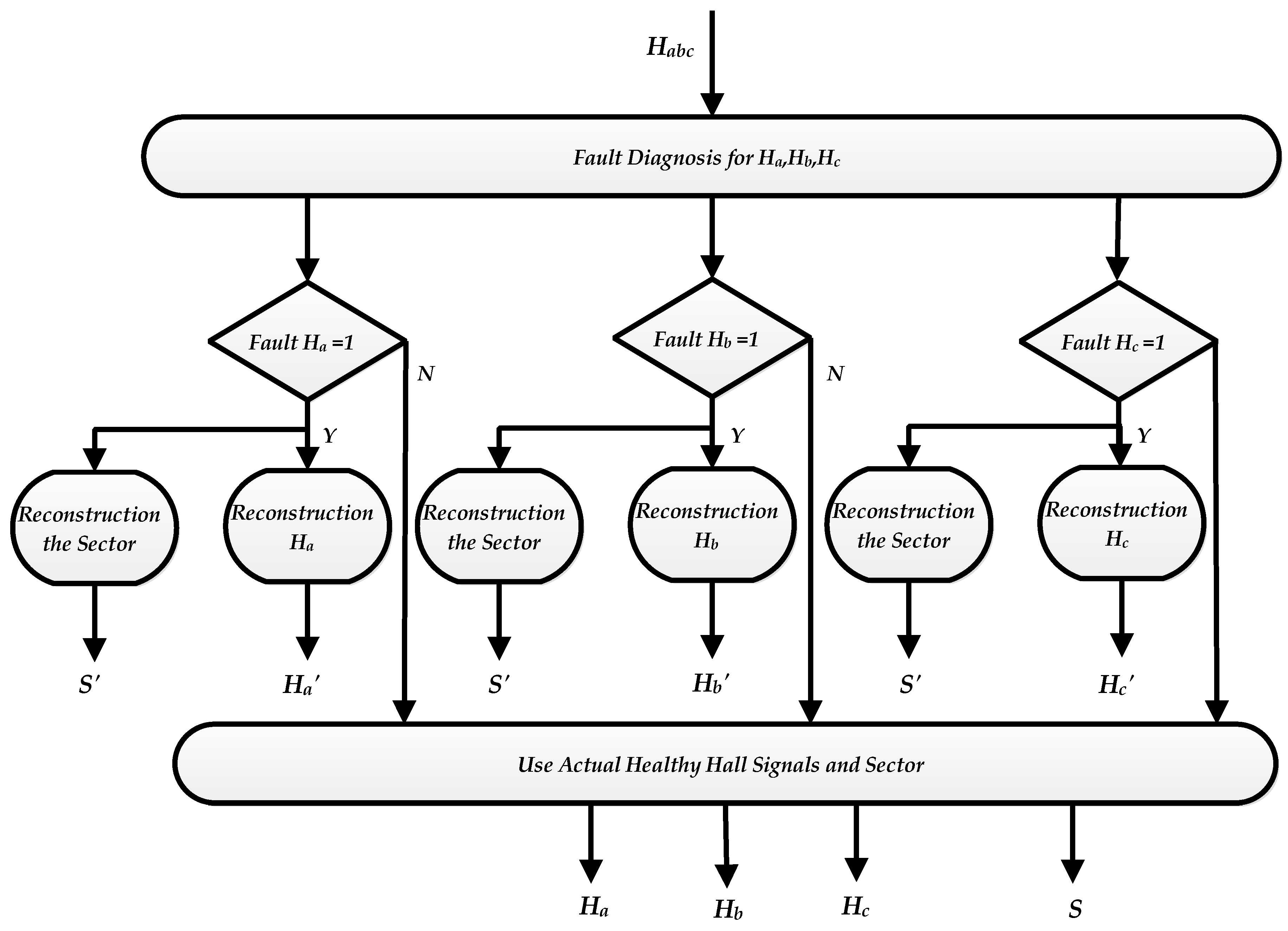
To simplify the contribution, the flowchart categorizes and explains the different steps for the proposed fault diagnosis and signal reconstruction; this flowchart is presented in Figure 7. We note that there are two types of outputs: the first type (S’, Ha, Hb, and Hc) consists of the signals built by the proposed method, and the second type (S, Ha, Hb, and Hc) consists of the actual signals [14]. This method can correct the defect if two Halls fail. We have used fault detection and signal reconstruction for each Hall sensor (Habc). Each sensor is debugged individually, knowing that the segment’s signal must be added if two Halls fail within the data set.

4. BLDC Motor Control Architecture

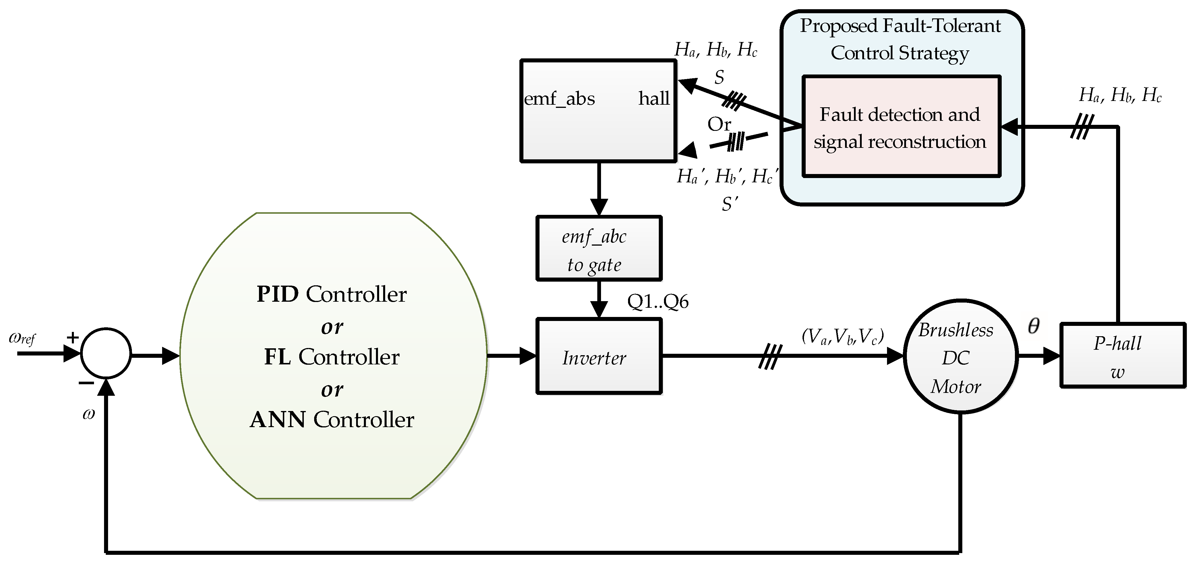
The global blocks on the Matlab Simulink platform were implemented as depicted in Figure 8. The acceleration ratio was determined by the driver or the given driving cycle. Once information is obtained about the vehicle’s actual speed, we can calculate the reference speed of the corresponding electric motor ( ω r e f ). Therefore, the control loop (PID, FLC, or ANN) will activate the motor control algorithm, which will calculate the needed commutation signals that will activate and deactivate the inverters. The inverter block will transmit the necessary power to the BLDCM after receiving the corresponding input voltage to supply the motor [29].

4.1. Proportional–Integral–Derivative Controller (PID)

The proportional–integral–derivative (PID) controller is a widely employed feedback control mechanism known for its simplicity and effectiveness in BLDC motors. The PID controller, whose terms are proportional (P), integral (I), and derivative (D), is generally used to improve the behavior of a system, i.e., to make the system more stable and to minimize the steady-state error. To achieve this purpose, the design process begins by understanding the dynamics of the system and defining the speed control objectives. By gathering information on the system’s behavior, stability, and time delays, engineers can establish the desired setpoint, response time, and steady-state error tolerance. The appropriate control algorithm, such as a standard PID controller or its modified versions, is then selected based on the specific system requirements. The PID controller is the perfect combination that corrects the problems caused in cases of using PI and PD controllers, such as through improving the steady-state error and maintaining the system’s stability [8]. Figure 9 shows the schematic of a PID [32,33,34].
The corresponding PID equation:
C ( s ) = K p + K i · 1 s + K d · s
where Kp = 0.15 is the proportional gain, Ki = 48 is the integral gain, and Kd = 0.001 is the derivative gain.
The process of tuning the PID controller involves adjusting the proportional, integral, and derivative gains to achieve the desired performance. Initially, the proportional gain (Kp) tuned by gradually increasing its value and observing the system’s response. This allows us to strike a balance between the response speed and stability. Next, the integral gain (Ki) is then introduced to eliminate steady-state error. Finally, the derivative gain (Kd) is employed to dampen overshoot and oscillations in the system. The iterative tuning process requires evaluating the system’s behavior and adjusting the gains accordingly.

4.2. Fuzzy Logic Controller

The fuzzy input vector should be defined first. It is composed of two variables: the speed error and its derivative [6,33].
{ e ( t ) = ω r e f * ω m a c t d e ( t ) d t = d ( ω r e f * ω m a c t ) d t
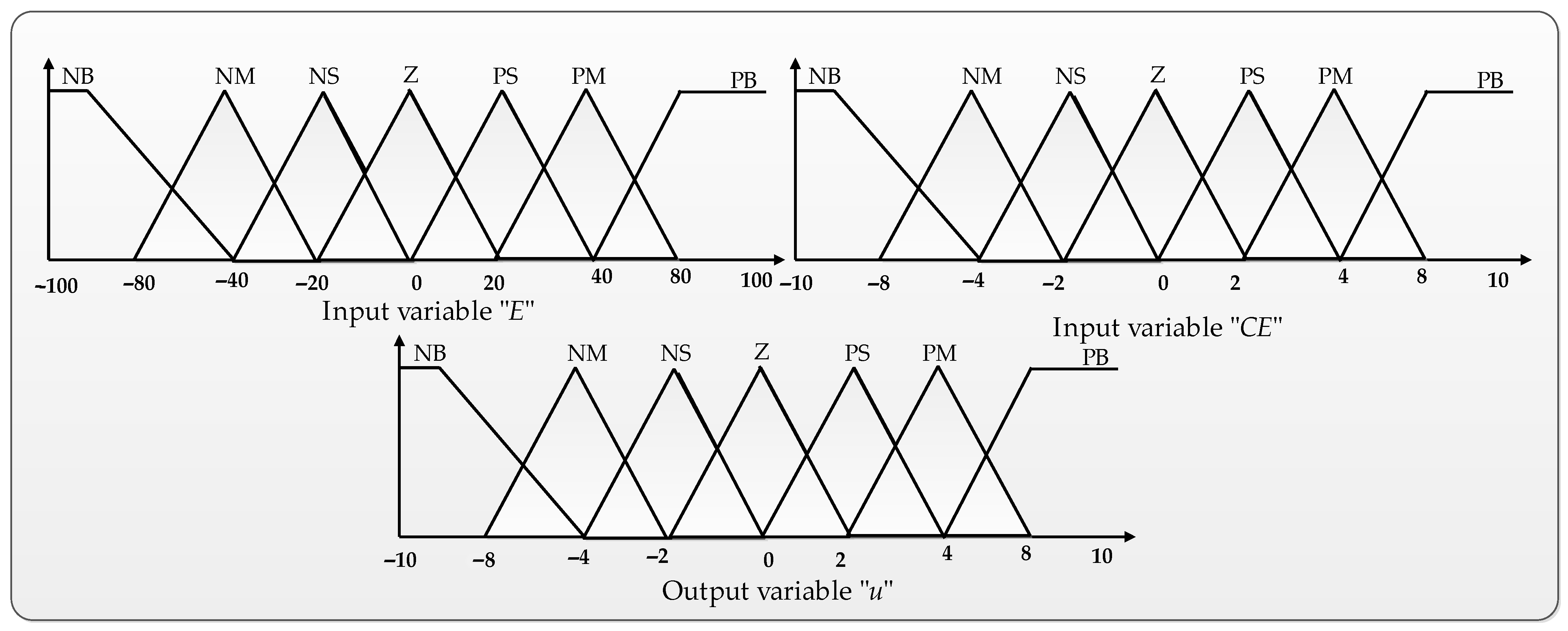
For comparison purposes, a fuzzy logic controller is implemented to test the performance of the system. In this case, the fuzzy logic controller uses operational laws presented in a linguistic form rather than relying solely on mathematical equations. Therefore, in this controller, the input and output variables are converted into linguistic variables via the fuzzification technique [35]. The fuzzy logic process is realized via passing through three main phases, which are fuzzification, knowledge base, and defuzzification. Figure 10 describes the structure of fuzzy logic control in Simulink MATLAB, including membership function plots, the input error “E”, the change in error “CE”, and the output variable “u”.
The triangle membership function was employed because of its effectiveness and simplicity. Seven fuzzy sets, including NB, NM, NS, Z, PS, PM, and PB, were used to categorize each discourse universe. As a result, following a rigorous series of analyses, the total 49 rules were justified, as shown in Table 5, and this look-up table was employed in the simulation program. To realize the simulation of the FLC controller, we used the Simulink tool in MATLAB software (MATLAB Version R2021a). It is also necessary to use the editor of the fuzzy inference system (FIS) to display the system’s general information (all the functions of the membership of entry and exit and the fuzzy rules).

4.3. Neural Network Controller

Because it can learn from an existing database to make the best decision in any case, the neural network system is referred to as an intelligent control solution [36]. The size of the database and the number of events determine the performance of any neural network controller. Nonetheless, the neural network architecture has an impact on the overall performance of this intelligent supervisor [35].
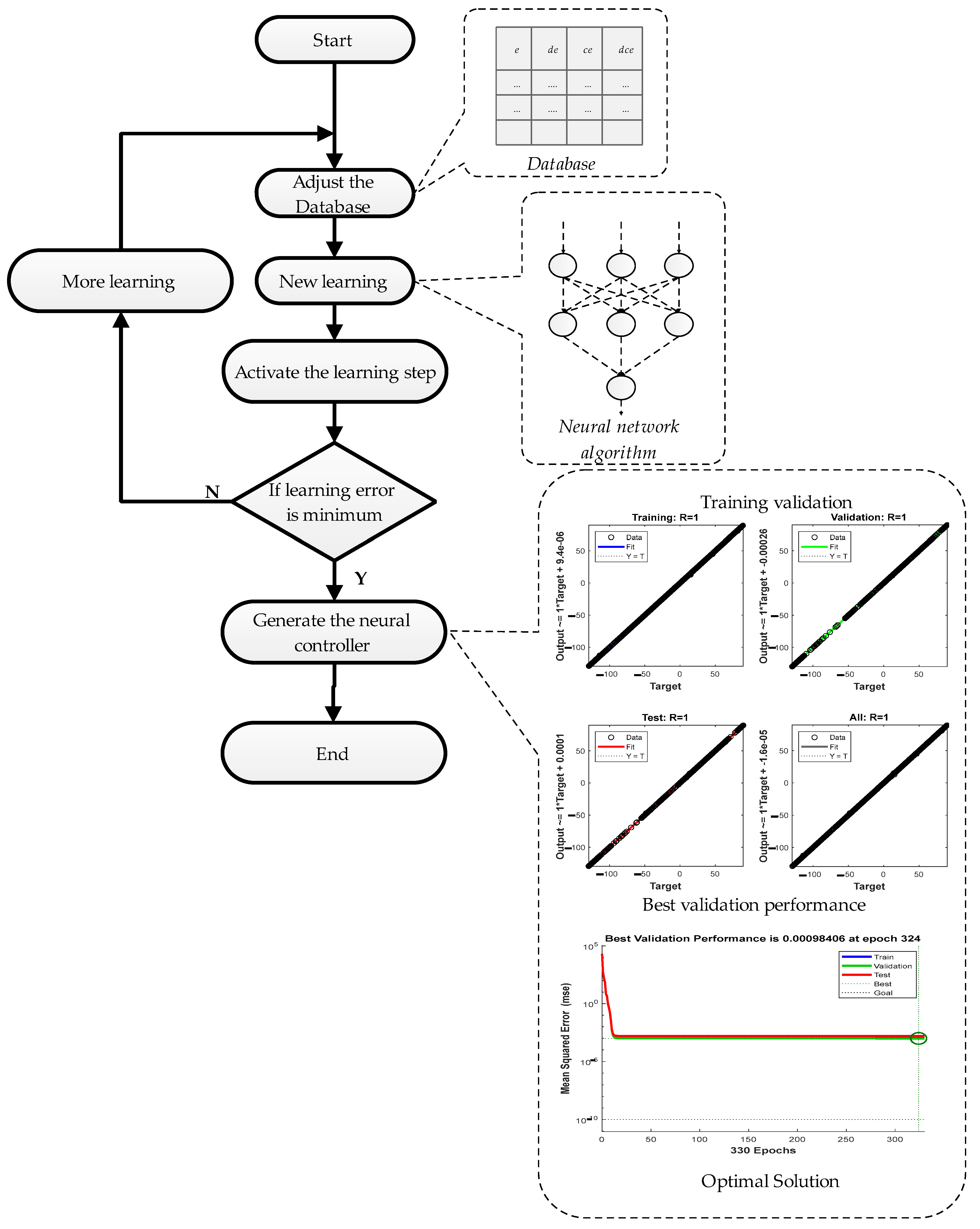
In this application, we made a database selection using 30,000 pieces of information. The next step, however, was the configuration of the neural network with three inputs and one output and to finally activate the learning. This neural network was trained using 5000 training epochs. A list of the neural network’s implemented layers and other parameters can be seen in Table 6.
The procedures in Figure 11 show the general steps for building a neural network controller that is adaptable to any control application with a real test validation performance.
The proposed algorithm consists of choosing multilayer neural networks to compare the found results with the desired results. It is necessary to change the biases and weights for different iterations to minimize the error.

5. Discussion of Simulation Results

The proposed study involved conducting simulations using MATLAB Simulink and taking advantage of the results of studies that successfully conducted experimental validations under similar conditions in order to assess the effectiveness of fault detection and identification in Hall effect sensors and the performance of the sector reconstruction algorithm [13,15,16,25]. We carried out different types of Hall sensor fault testing on a BLDC motor. We observed the following at each test: the three signals, Ha, Hb, and Hc, the sector created by the standard control algorithm, the sector reconstructed by the proposed approach, the currents in the three phases of the BLDC motor, and the rotor velocity.
Two tests were performed. The first test aimed to rigorously verify the efficiency of the detection and identification of faults proposed in the Hall effect sensors and the capacity of the sector reconstruction algorithm. The second test aimed to identify the different BLDC drive characteristics of each speed controller (PID, FL, and ANN) and how each speed controller operated in the event of a fault. The different parameters of the engine studied in this work are listed in Table 7 [37].
In this work, we opted for a simulation time equal to 4 s. Indeed, to test the sensor fault, we applied a defect to sensor Ha; then, to improve the visualization of the defect, we increased the curves obtained from 1.95 s to 2.05 s, as indicated in the figures below.

5.1. Signal Faults and Reconstructed Sector

In this part, we present the results obtained for various simulation conditions to show the effectiveness of the proposed method. For this purpose, we have treated two critical cases, case 1, a steady state, and case 2, a transient state, to show that the proposed fault-tolerant control strategy works in all possible cases.
A. 
Case 1: In a Steady State:
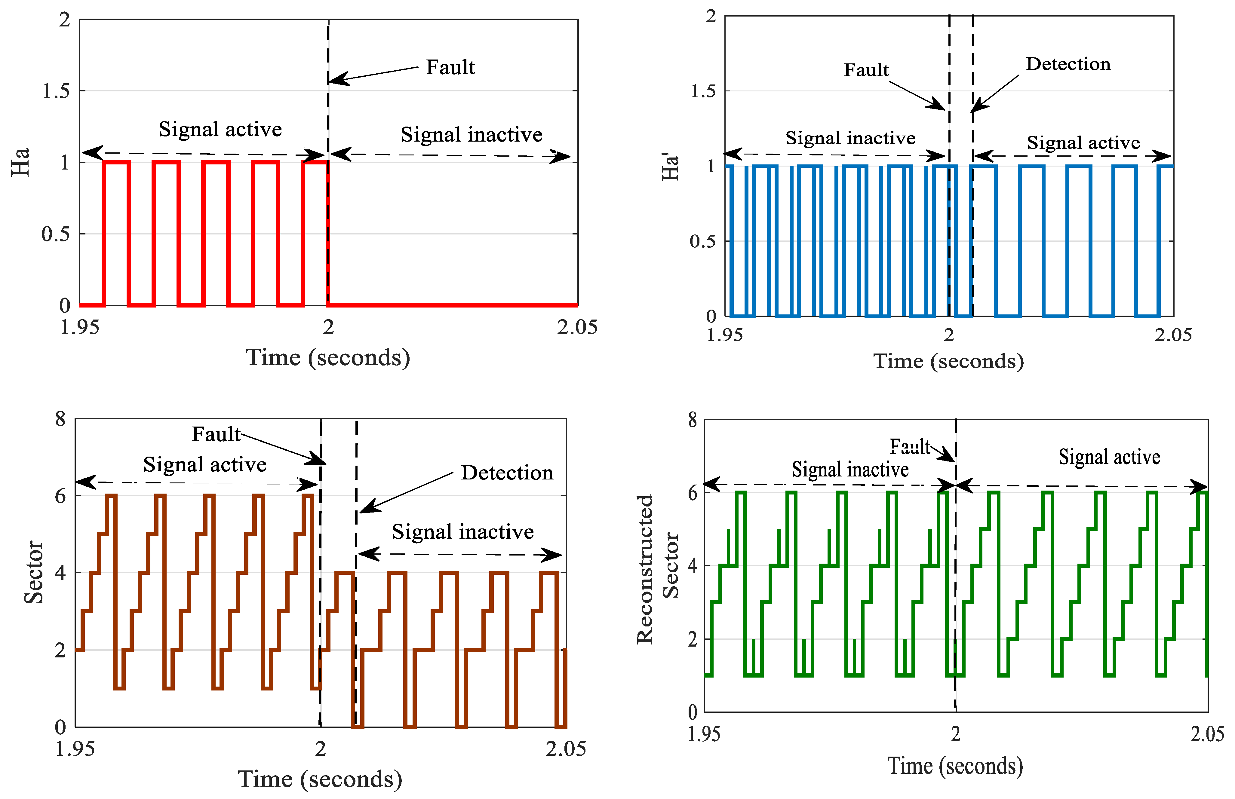
Figure 12 depicts the behavior in case 5: sensor Ha fails in the midst of sector 1, and Ha flips from 1 to 0 and remains there. The problem is discovered at the beginning of sector 6 as expected, and there are incorrect commutations in sector 5 and the remainder of sector 1. In Figure 12, we note that after the fault of the Ha sensor and sector, the proposed FTC was activated and generated the new sector, S’ and Ha.
When one of the motor sensors fails, the motor speed and current are affected, as shown in Figure 13. The error in case 5 affects negatively the speed condition, but there is a slight delay and then the failure occurs in sector 2.
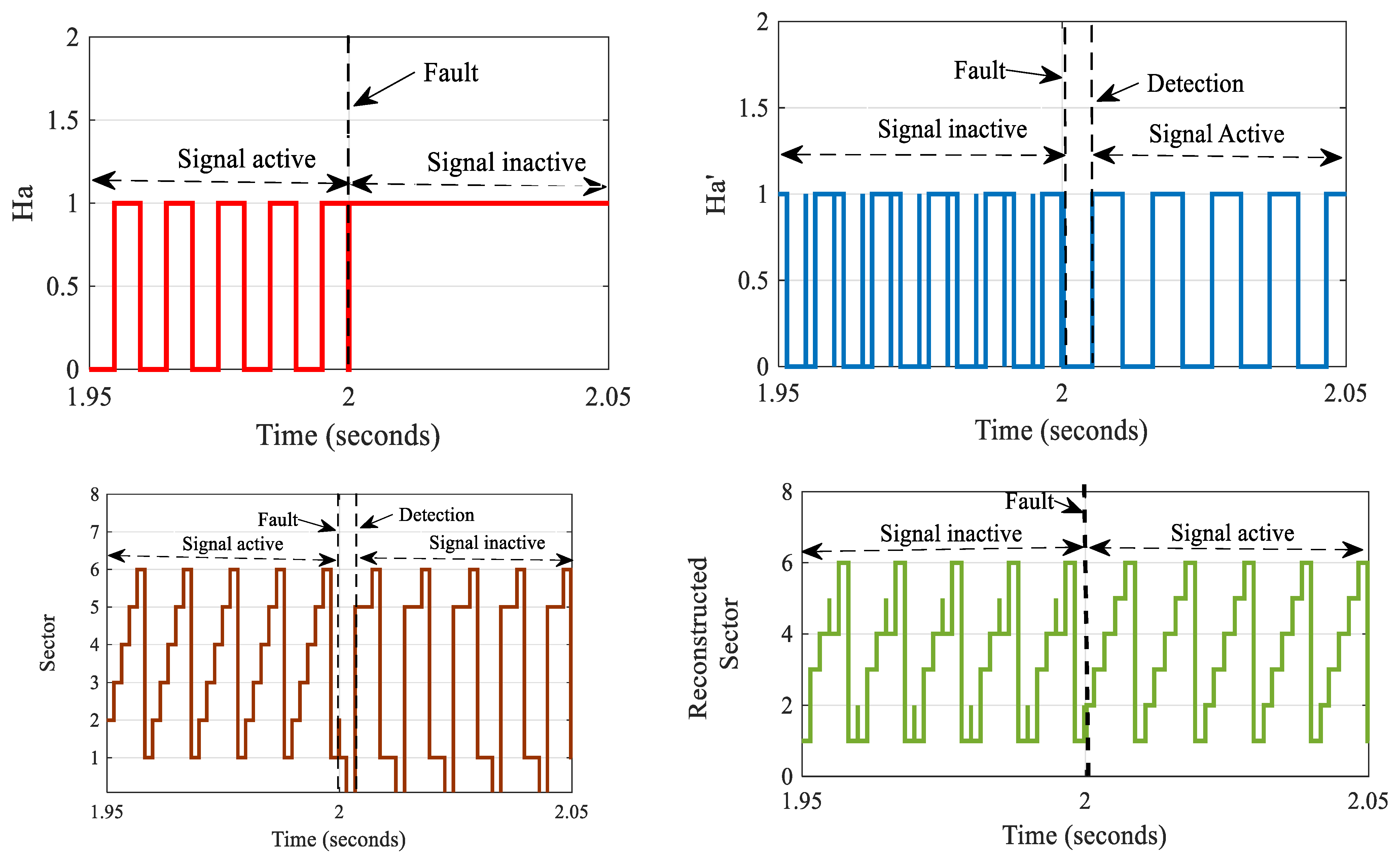
For case 6, the behavior is depicted in Figure 14: sensor Ha does not perform any transition at the end of sector 1, and its value remains constant at 1. The defect is identified at the start of sector 3 as expected, and there are incorrect commutations in sector 2, finally generating the new sector, S’ and Ha.
When there is a fault in one of the motor sensors, this error affects the motor speed and the current, as shown in Figure 15. The error in case 6 affects negatively the speed condition. Furthermore, there was no delay in the failure that occurred in sector 2, as the current was exposed to loss and imbalance in the pattern.
Figure 16 depicts the behavior in case 1: the Ha signal changes from 0 to 1 in the middle of sector 2. As expected, the breakdown is identified promptly, and no incorrect commutation occurs in any sector, with no effect on the operation of the motor, which finally generates the new sector, S’ and Ha, shortly after the fault occurrs.
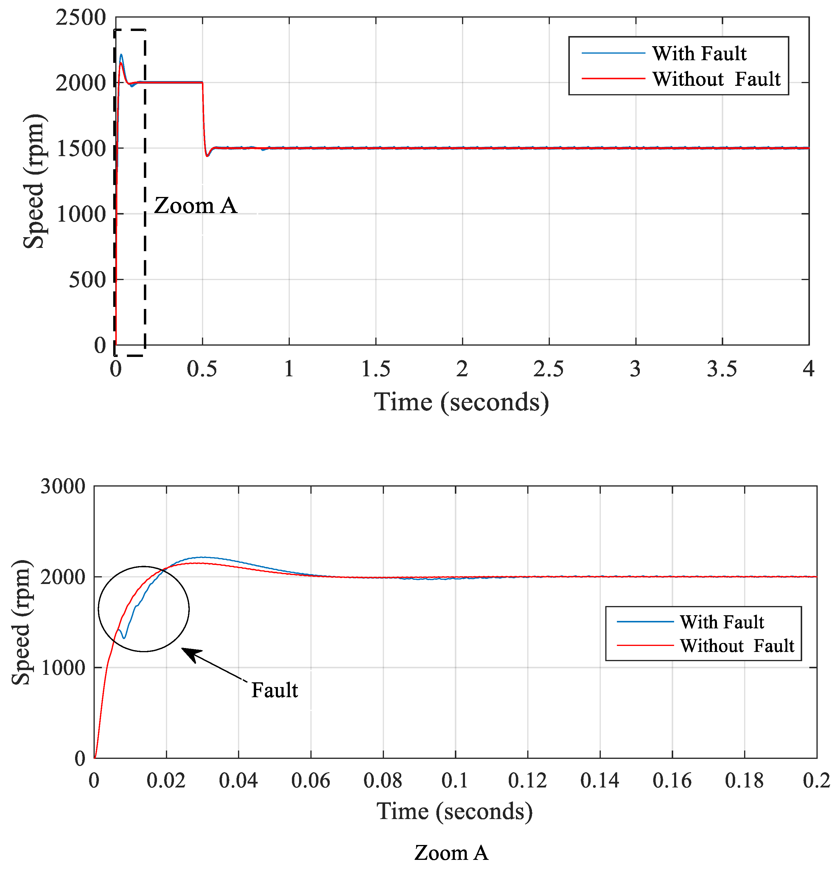
The speed curve in Figure 17 describes two phases: first, the fault case, and then the operating case, which comes after the fault. For the speed at which the fault appeared at t = 2 s, the system begins to become disturbed by reaching a maximum of 1600 rpm and a minimum of 1250 rpm. For the current case, the second phase in the fault state corresponds to t = 2 s, when the curves of the three phases become disturbed.
Figure 12, Figure 13, Figure 14, Figure 15, Figure 16 and Figure 17 depict the startups with faulty Ha from the respective sectors. The results show that the suggested method provides a satisfactory startup in all cases and can be applied to operate the BLDC motor correctly, even when a Hall effect sensor fails.
B. 
Case 2: In the Transient State:
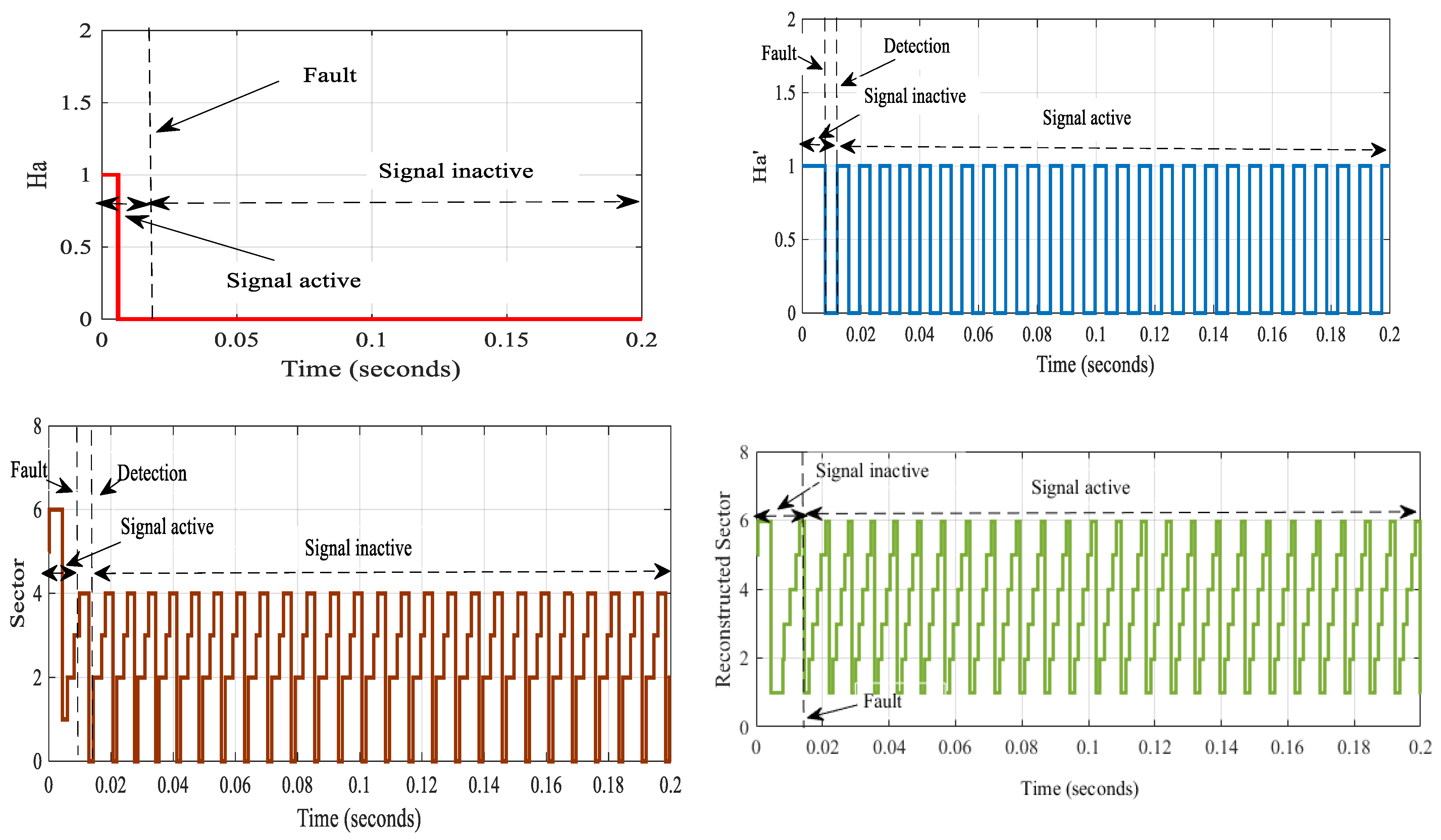
At this stage, and to simplify the idea, we applied the fail at t = 0.006 s, i.e., in the transient case. Figure 18 depicts the behavior in the transient state of sensor Ha in sector 4; this failure is caught when sector 5 is converted into sector 0.
The problem is discovered at the beginning of sector 5 as expected, and there are incorrect commutations in sector 5, and the distorted sector is as follows:
sector 2 → sector 2 → sector3 → sector 4→ sector 4→ sector 0
We note that in Figure 18, after the fault of the Ha sensor and sector, the proposed FTC in the transient state case was activated and generated the new sector, S’ and Ha’.
To test the effectiveness of the proposed FTC, we chose a simple PID speed controller and implemented a transient state error. Figure 19 shows the effectiveness of the proposed FTC and its effect on the speed. The effect of the fault on the speed remained within limits, 0.054 s, which is a very small time, and this time confirms the efficiency of the proposed method in all cases.

5.2. Efficiency for the Proposed Speed Control with Fault-Tolerant Control

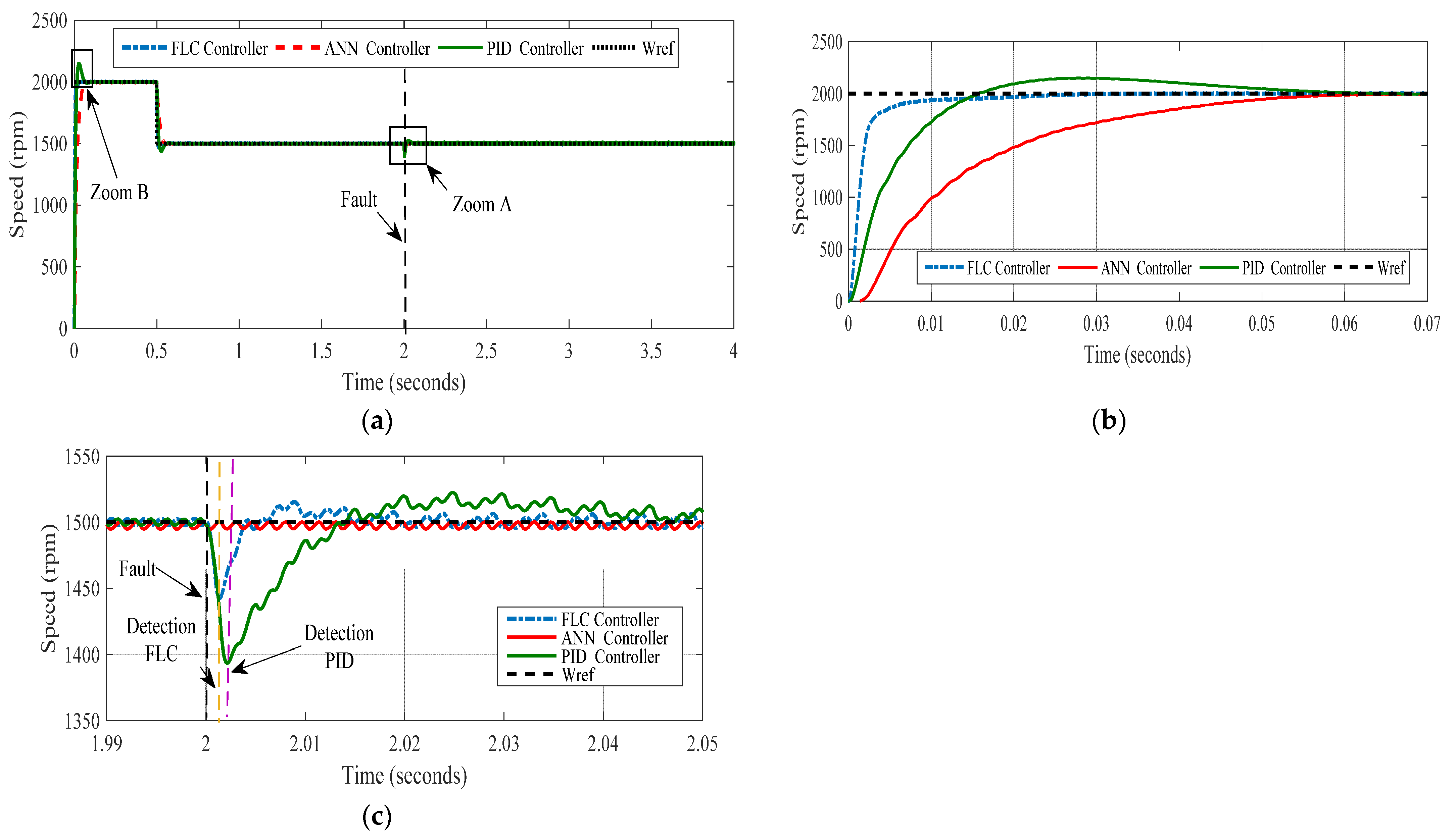
Figure 20a shows the motor’s speed curves, describing each controller’s speed effect. In the zoom B phase, the PID controller shows a speed exceeding 2100 rpm, with an overrun time that reaches 0.05 s. The fuzzy logic case’s speed reaches 2000 rpm, with a short overrun time of 0.01 s. For the neural network case, the speed is the closest to the reference speed, which allows us to select the ANN controller as the best in terms of speed.
Figure 20c is characterized by the evidence of sensor failure from which each controller proves its ability to detect failure. The PID controller deforms after a failure of a duration of 2.013 s, while the FLC controller recovers its operation after a period of about 2.0025 s. The ANN controller resists the failure by continuing the operation despite the occurrence of the fault.
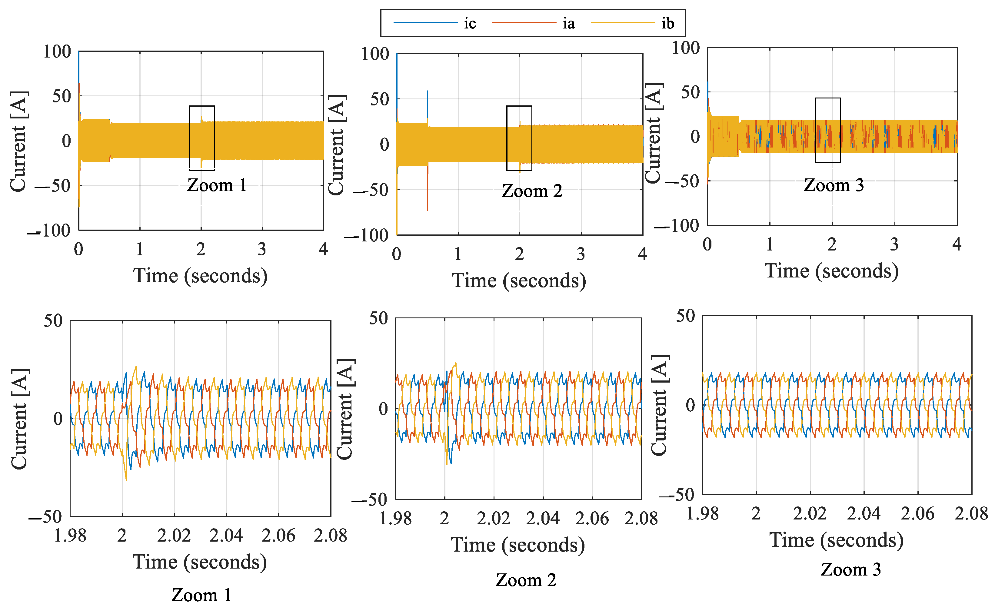
The different current curves show the efficiency of the ANN controller in front of the PID and FLC controllers. A peak is reached at the time 2 s during the appearance of the fault; this peak is the maximum in the case of the PID controller, as shown in Figure 21.
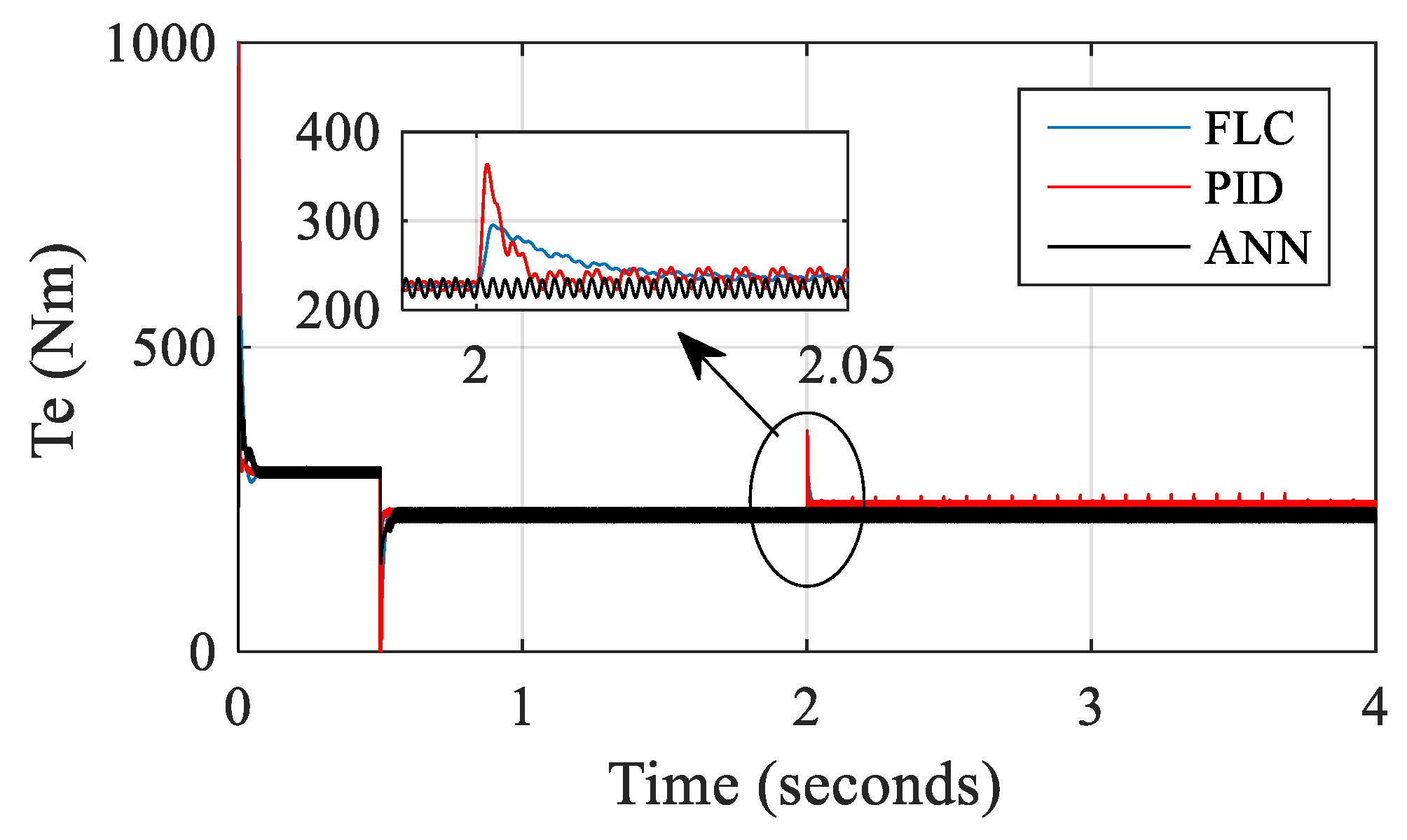
The torque results for each controller are shown in Figure 22. For the case of a PID controller, for instance, at startup, the speed shows a peak of 370 N.m; its value then stabilizes around 220 N.m. In the case of the fuzzy logic controller, the curve shows a less important peak than that of the FLC, but the most stable torque results are attributed to the ANN controller.

5.3. Comparison of Different Control Strategies

Table 8 summarizes the key specifications of the different control techniques. We conducted an evaluation and comparison of the different controllers based on their response characteristics and identified distinct features to distinguish each of them. The simple PID controller is the most generally utilized according to the literature; nevertheless, compared to the fuzzy controller and neural network controller, its overall energy performance can be anticipated to be lower than the performances realized by the other controllers. Based on this data, it is apparent that this kind of control impacts the overall performance and the profitability of the BLDC motor by increasing them. This work also shows that achieving speed control through the use of a neural network with FTC is the best control strategy for the application of a BLDC motor.

6. Conclusions

This paper presents the application of an innovative fault-tolerant control method specifically designed for a brushless permanent magnet DC motor utilized in electric vehicles. To detect the rotor position, Hall-type sensors are used by attaching them to the stator to generate Ha, Hb, and Hc signals if the rotor rotates. The control focuses only on the Hall effect sensors used. To ensure operational continuity, various speed controllers, including fuzzy logic and neural network controllers, were adopted and tested. According to the simulation results, the fuzzy logic controller recovered its operation faster than the PID controller. Moreover, the neural network controller proved to be more effective than the other two types of controllers. This work also shows that achieving speed control through the use of a neural network with FTC is the best control strategy for the application of a BLDC motor. With this control strategy, the EVs’ performances were improved as the vehicle speed performances became more important, proving the vehicles’ total profitability. While our current research primarily focuses on the theoretical aspects of fault-tolerant control strategies, we recognize the importance of conducting extensive experimental studies as part of future work.

Author Contributions

Methodology, M.N.; Software, M.A.B., M.N. and M.C.; Validation, M.A.B., M.N. and M.C. All authors have read and agreed to the published version of the manuscript.

Funding

This research received no external funding.

Institutional Review Board Statement

Not applicable.

Informed Consent Statement

Not applicable.

Data Availability Statement

The data presented in this study are available on request from the corresponding author.

Acknowledgments

This work was accomplished thanks to the grant provided by Organization for Women in Science for the Developing World (OWSD) and the Swedish International Development Cooperation Agency (SIDA). The author wishes to express his gratitude to the OWSD and SIDA for the opportunity and the support given.

Conflicts of Interest

The authors declare no conflict of interest.
Abbreviations
EVsElectric vehicles
BLDCMBrushless DC motor
BLDCBrushless DC
EMF Electromotive force
PMSMPermanent magnet synchronous motor
PIDProportional–integral–derivative controller
FLCFuzzy logic control
ANNNeural network control
FTCFault-tolerant control
List of symbols
Kp, Ki, KdProportional, integral, and derivative gains
Va,Vb,VcPhase voltages a,b,c
ia,ib,icPhase currents a,b,c
ωRotor speed
JMoment of inertia
Q1Q6Switching states
ke Coefficient of the electromotive force
LInductance
BCoefficient of friction
f ( θ e ) Functions depending on rotor position
TeElectromagnetic torque
TrLoad torque
SSector
S’Reconstruction sector

References

  1. Primiceri, P.; Visconti, P.; Melpignano, A.; Colleoni, G.; Vilei, A. Hardware and software solution developed in arm MBED environment for driving and controlling DC brushless motors based on ST X-Nucleo development boards. Int. J. Smart Sens. Intell. Syst. 2016, 9, 1534–1562. [Google Scholar] [CrossRef] [Green Version]
  2. Singh, K.V.; Bansal, H.O.; Singh, D. A comprehensive review on hybrid electric vehicles: Architectures and components. J. Mod. Transp. 2019, 27, 77–107. [Google Scholar] [CrossRef] [Green Version]
  3. Eldho Aliasand, A.; Josh, F.T. Selection of Motor foran Electric Vehicle: A Review. Mater. Today Proc. 2020, 24, 1804–1815. [Google Scholar] [CrossRef]
  4. Yildirim, M.; Polat, M.; Kurum, H. A survey on comparison of electric motor types and drives used for electric vehicles. In Proceedings of the 16th International Power Electronics and Motion Control Conference and Exposition, Antalya, Turkey, 21–24 September 2014; pp. 218–223. [Google Scholar] [CrossRef]
  5. Baba, M.A.; Naoui, M.; Cherkaoui, M. Modeling and Simulation of a BLDC Motor Speed Control in Electric Vehicles. Int. Conf. Digit. Technol. Appl. 2023, 1, 883–895. [Google Scholar] [CrossRef]
  6. Goswami, R.; Joshi, D. Performance Review of Fuzzy Logic Based Controllers Employed in Brushless DC Motor. Procedia Comput. Sci. 2018, 132, 623–631. [Google Scholar] [CrossRef]
  7. Kristiyono, R. Wiyono Autotuning fuzzy PID controller for speed control of BLDC motor. J. Robot. Control 2021, 2, 400–407. [Google Scholar] [CrossRef]
  8. Ramírez-Cárdenas, O.-D.; Trujillo-Romero, F. Sensorless Speed Tracking of a Brushless DC Motor Using a Neural Network. Math. Comput. Appl. 2020, 25, 57. [Google Scholar] [CrossRef]
  9. Zhang, R.; Gao, L. The Brushless DC motor control system Based on neural network fuzzy PID control of power electronics technology. Optik 2022, 271, 169879. [Google Scholar] [CrossRef]
  10. Gamazo-Real, J.C.; Vázquez-Sánchez, E.; Gómez-Gil, J. Position and speed control of brushless dc motors using sensorless techniques and application trends. Sensors 2010, 10, 6901–6947. [Google Scholar] [CrossRef] [Green Version]
  11. Vanchinathan, K.; Valluvan, K.T.R.; Gnanavel, C.; Gokul, C.; Renold, R.A. An improved incipient whale optimization algorithm based robust fault detection and diagnosis for sensorless brushless DC motor drive under external disturbances. Int. Trans. Electr. Energy Syst. 2021, 31, e13251. [Google Scholar] [CrossRef]
  12. Naoui, M.; Flah, A.; Sbita, L.; Ben Hamed, M.; Azar, A.T. Intelligent Control System for Hybrid Electric Vehicle with Autonomous Charging. In Artificial Intelligence for Robotics and Autonomous Systems Applications; Azar, A.T., Koubaa, A., Eds.; Springer International Publishing: Cham, Switzerland, 2023; pp. 405–437. ISBN 978-3-031-28715-2. [Google Scholar]
  13. Mousmi, A.; Abbou, A.; El Houm, Y. Binary Diagnosis of Hall Effect Sensors in Brushless DC Motor Drives. IEEE Trans. Power Electron. 2020, 35, 3859–3868. [Google Scholar] [CrossRef]
  14. Zhang, Q.; Feng, M. Fast Fault Diagnosis Method for Hall Sensors in Brushless DC Motor Drives. IEEE Trans. Power Electron. 2019, 34, 2585–2596. [Google Scholar] [CrossRef]
  15. Ebadpour, M.; Amiri, N.; Jatskevich, J. Fast Fault-Tolerant Control for Improved Dynamic Performance of Hall-Sensor-Controlled Brushless DC Motor Drives. IEEE Trans. Power Electron. 2021, 36, 14051–14061. [Google Scholar] [CrossRef]
  16. Zhao, Y.; Huang, W.; Yang, J. Fault diagnosis of low-cost hall-effect sensors used in controlling permanent magnet synchronous motor. In Proceedings of the 19th International Conference on Electrical Machines and Systems (ICEMS), Chiba, Japan, 13–16 November 2017; pp. 2–6. [Google Scholar]
  17. Gayatri Sarman, K.V.S.H.; Madhu, T.; Mallikharjuna Prasad, A. Fault diagnosis of BLDC drive using advanced adaptive network-based fuzzy inference system. Soft Comput. 2021, 25, 12759–12774. [Google Scholar] [CrossRef]
  18. Shifat, T.A.; Hur, J.W. EEMD assisted supervised learning for the fault diagnosis of BLDC motor using vibration signal. J. Mech. Sci. Technol. 2020, 34, 3981–3990. [Google Scholar] [CrossRef]
  19. Kumar, P.H.; Somasekhar, V.T. An Enhanced Fault-Tolerant and Autoreconfigurable BLDC Motor Drive for Electric Vehicle Applications. IEEE J. Emerg. Sel. Top. Ind. Electron. 2022, 4, 368–380. [Google Scholar] [CrossRef]
  20. Mohamed, N.; Aymen, F.; Mouna, B.H.; Lassaad, S. Modeling and simulation of vector control for a Permanent Magnet Synchronous Motor in electric vehicle. In Proceedings of the 4th International Symposium on Advanced Electrical and Communication Technologies (ISAECT), Alkhobar, Saudi Arabia, 6–8 December 2021; pp. 1–5. [Google Scholar]
  21. Obed, A.A.; Kadhim, A.K. Speed and Current Limiting Control Strategies for BLDC Motor Drive System: A Comparative Study. Int. J. Adv. Eng. Res. Sci. 2018, 5, 119–130. [Google Scholar] [CrossRef]
  22. Mondal, S.; Mitra, A.; Chattopadhyay, M. Mathematical modeling and simulation of Brushless DC motor with ideal Back EMF for a precision speed control. In Proceedings of the IEEE International Conference on Electrical, Computer and Communication Technologies (ICECCT), Coimbatore, India, 5–7 March 2015; pp. 15–19. [Google Scholar] [CrossRef]
  23. Krause, P.C.; Wasynczuk, O.; Sudhoff, S.D. Brushless dc Motor Drives. In Analysis of Electric Machinery and Drive Systemsl; Wiley-IEEE Press: Piscataway, NJ, USA, 2010. [Google Scholar] [CrossRef]
  24. Tibor, B.; Fedak, V.; Ďurovský, F. Modeling and simulation of the BLDC motor in MATLAB GUI. In Proceedings of the IEEE International Symposium on Industrial Electronics, Gdansk, Poland, 27–30 June 2011; pp. 1403–1407. [Google Scholar] [CrossRef]
  25. Zhang, X.; Zhao, Y.; Lin, H.; Riaz, S.; Elahi, H. Real-time fault diagnosis and fault-tolerant control strategy for hall sensors in permanent magnet brushless dc motor drives. Electronics 2021, 10, 1268. [Google Scholar] [CrossRef]
  26. Dong, L.; Jatskevich, J.; Huang, Y.; Chapariha, M.; Liu, J. Fault diagnosis and signal reconstruction of hall sensors in brushless permanent magnet motor drives. IEEE Trans. Energy Convers. 2016, 31, 118–131. [Google Scholar] [CrossRef]
  27. Aqil, M.; Hur, J. A Direct Redundancy Approach to Fault-Tolerant Control of BLDC Motor with a Damaged Hall-Effect Sensor. IEEE Trans. Power Electron. 2020, 35, 1732–1741. [Google Scholar] [CrossRef]
  28. Tashakori, A.; Ektesabi, M. Position sensors fault tolerant control system in BLDC motors. Eng. Lett. 2014, 22, 39–46. [Google Scholar]
  29. Aqil, M.; Hur, J. Multiple sensor fault detection algorithm for fault tolerant control of bldc motor. Electronics 2021, 10, 1038. [Google Scholar] [CrossRef]
  30. Dong, L.; Huang, Y.; Jatskevich, J.; Liu, J. Improved Fault-Tolerant Control for Brushless Permanent Magnet Motor Drives with Defective Hall Sensors. IEEE Trans. Energy Convers. 2016, 31, 789–799. [Google Scholar] [CrossRef]
  31. Magistrale, L. Sensorless Brushless DC Motors: Development and comparison of different fault tolerant control algorithms. 2018; 2005, (Doctoral dissertation, Politecnico di Torino). [Google Scholar]
  32. Mousa, M.E.; Ebrahim, M.A.; Hassan, M.A.M. Stabilizing and Swinging-Up the Inverted Pendulum Using PI and PID Controllers Based on Reduced Linear Quadratic Regulator Tuned by PSO. Int. J. Syst. Dyn. Appl. 2015, 4, 52–69. [Google Scholar] [CrossRef]
  33. Sushita, K. Performance of BLDC motor with PI, PID and Fuzzy controller and its Comparative Analysis. Eur. J. Mol. Clin. Med. 2021, 25, 219–228. [Google Scholar]
  34. Singh, G.; Kour, V.; Singh, L. Design and Performance Analysis of PID Controller for Automatic Generation Control of an Autonomous Power System. Int. J. Eng. Res. Technol. 2020, 7, 2520–2524. [Google Scholar]
  35. Kilic, E.; Yilmaz, S.; Ozcalik, H.R.; Sit, S. A comparative analysis of FLC and ANFIS controller for vector controlled induction motor drive. In Proceedings of the Intl Aegean Conference on Electrical Machines & Power Electronics (ACEMP), 2015 Intl Conference on Optimization of Electrical & Electronic Equipment (OPTIM) & 2015 Intl Symposium on Advanced Electromechanical Motion Systems (ELECTROMOTION), Side, Turkey, 2–4 September 2015; pp. 102–106. [Google Scholar] [CrossRef]
  36. Mishra, S.; Anurag, M.; Tomer, S. Speed Control of PMSM Drives by Using Neural Network Controller. Adv. Electron. Electr. 2014, 4, 353–360. [Google Scholar]
  37. Huang, C.; Lei, F.; Han, X.; Zhang, Z. Determination of modeling parameters for a brushless DC motor that satisfies the power performance of an electric vehicle. Meas. Control 2019, 52, 765–774. [Google Scholar] [CrossRef] [Green Version]
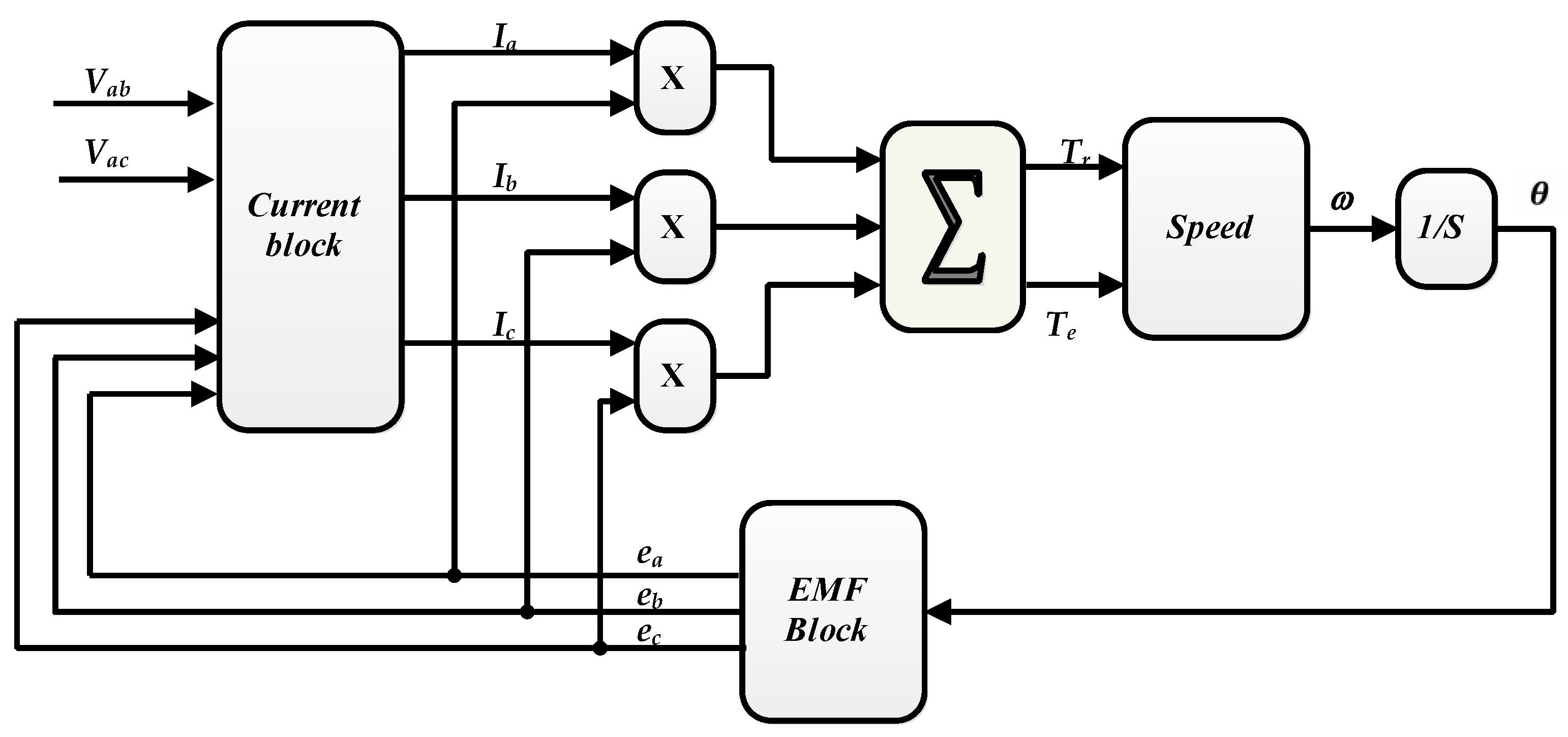
Figure 1. Flow chart of the simulated machine model.
Sustainability 15 10430 g001
Figure 2. Typical Hall-sensor-controlled BLDC motor drive system.
Sustainability 15 10430 g002
Figure 3. Standard sensor signals: (a) Hall sensor signals; (b) sector signals.
Sustainability 15 10430 g003aSustainability 15 10430 g003b
Figure 4. For case Ha = 0: (a) sensor signals; (b) sector signals.
Sustainability 15 10430 g004
Figure 5. For case Ha = 1: (a) sensor signals; (b) sector signals.
Sustainability 15 10430 g005
Figure 6. Shows a proposed combinatorial circuit for detecting flaws in Hall sensor Ha.
Sustainability 15 10430 g006
Figure 7. Block diagram of the Hall signals and the sector for the reconstruction method.
Sustainability 15 10430 g007
Figure 8. Block diagram of BLDC motor.
Sustainability 15 10430 g008
Figure 9. Block diagram of a PID controller.
Sustainability 15 10430 g009
Figure 10. Membership function plot for input and output variables.
Sustainability 15 10430 g010
Figure 11. Steps of implementing a neural network controller.
Sustainability 15 10430 g011
Figure 12. Results of the proposed FTC in case 5.
Sustainability 15 10430 g012
Figure 13. Speed and current responses under fault and non-fault conditions in case 1.
Sustainability 15 10430 g013
Figure 14. Results of the proposed FTC in situation 6.
Sustainability 15 10430 g014
Figure 15. Speed and current responses under fault and non-fault conditions in situation 6.
Sustainability 15 10430 g015
Figure 16. Results of the proposed FTC in situation 1.
Sustainability 15 10430 g016
Figure 17. Speed and current responses under fault and non-fault conditions situation 1.
Sustainability 15 10430 g017
Figure 18. Proposed FTC in transient state.
Sustainability 15 10430 g018
Figure 19. Speed and responses under fault in transient state.
Sustainability 15 10430 g019
Figure 20. Speed of the BLDC motor according to the different controllers used (PID, FLC, and ANN) in the presence of faults. (a): speed, (b) zoom B, and (c) zoom A.
Sustainability 15 10430 g020
Figure 21. Current phase curves of different controllers (PID, FLC, and ANN) in the presence of faults.
Sustainability 15 10430 g021
Figure 22. The motor’s electromagnetic torque results for the three control cases (FLC, PID, and ANN).
Sustainability 15 10430 g022
Table 1. The output signals from Hall effect sensors.
θ e HaHbHc
0 < θ e < 30 100
30 < θ e < 90 110
90 < θ e < 150 010
150 < θ e < 210 011
210 < θ e < 270 001
270 < θ e < 330 101
330 < θ e < 360 100
Table 2. States of Hall effect sensors and active switches in conventional BLDC drives.
HaHbHcSectorActive SwitchesStator Magnetic Axis
1101Q3 Q6V2
0102Q3 Q2V3
0113Q5 Q2V4
0014Q5 Q4V5
1015Q1 Q4V6
1006Q1 S6V1
Table 3. States of Hall effect sensors and active switches in operation with faults in “Ha = 0” and “Ha = 1”.
Ha = 0
HaHbHcSectorActive SwitchesStator Magnetic Axis
0102Q3 Q2V3
010
0113Q5 Q2V4
0014Q5 Q4V5
001
0000No0
Ha = 1
HaHbHcSectorActive SwitchesStator Magnetic Axis
1101Q3 Q6V2
110
1110No one0
1015Q1 Q4V6
101
1006Q1 Q6V1
Table 4. Causes of sensor failures (Ha = 0 and Ha = 1).
Ha = 0
CasesFailure SectorSector Switches From
Case 16 in (from 0° to 30°)From 6 to 0 H a ¯ · H b ¯ ·   H c ¯ = 1
Case 21 in (30–90°)From 1 to 2 H a ¯ · H b · H c ¯ = 1
Case 35 in (270–330°)From 5 to 6 H a ¯ · H b ¯ · H c = 1
Case 46 in (from 330° to 360°)From 6 to 0 H a ¯ · H b ¯ · H c ¯ = 1
Ha = 1
CasesFailure SectorSector Switches from
Case 52 in (from 90° to 150°)From 2 to 1 H a · H b · H c ¯ = 1
Case 63 in (150–210°)From 3 to 0 H a · H b · H c = 1
Case 74 in (210–270°)From 4 to 5 H a · H b ¯ · H c = 1
Table 5. Fuzzy rule look-up table.
E/CENBNMNSZPSPMPB
NBNBNBNBNBNMNSZ
NMNBNBNBNMNSZPS
NSNBNBNMNSZPSPM
ZNBNMNSZPSPMPB
PSNMNSZPSPMPBPB
PMNSZPSPMPBPBPB
PBZPSPMPBPBPBPB
NB: negative big; NM: negative medium; NS: negative small; Z: zero; PS: positive small; PM: positive medium; PB: positive big.
Table 6. Summary of the parameters of the proposed neural network.
ParameterValue
Input elements3
Output element1
Training70%
Validation15%
Testing15%
Number of Hidden Neurons10
Training AlgorithmLevenberg–Marquardt
Epochs5000
Table 7. BLDC motor parameters.
ParameterValue
Base velocity2300 (r/min)
Stator inductance58.9 µH
Supply voltage400 v
Maximum power (kW)90
Magnet excitation flux0.0030225 wb
Number of pairs of poles4
e.m.f. constant (ke)0.18
Moment of inertia of rotating parts (j)0.0000528 n.m.s2
Stator resistance0.025 ω
Table 8. Comparison of control techniques.
Controller Type Control System Parameters
Settling Time (s)Peak OvershootSteady Stat ErrorNumbers of OscillationsResponse Time When a Signal Fault
PID controller 0.07Low0.61Medium
FLC controller0.02NilVery lowNilLow
ANN controller0.06NilVery lowNil-
Disclaimer/Publisher’s Note: The statements, opinions and data contained in all publications are solely those of the individual author(s) and contributor(s) and not of MDPI and/or the editor(s). MDPI and/or the editor(s) disclaim responsibility for any injury to people or property resulting from any ideas, methods, instructions or products referred to in the content.