Article

Pipe Piles and Key Stratum Modeling for Grouting Reinforcement of Mine Floors under Mining Disturbance and Microseismic Monitoring Evaluation

1
Jizhong Energy Group Corporation Ltd., Xingtai 054000, China
2
School of Energy and Mining Engineering, China University of Mining and Technology—Beijing, Beijing 100083, China
3
Hebei Coal Sciences Research Institute Corporation Ltd., Xingtai 054000, China
*
Author to whom correspondence should be addressed.
Sustainability 2023, 15(12), 9294; https://doi.org/10.3390/su15129294
Submission received: 19 March 2023 / Revised: 1 June 2023 / Accepted: 5 June 2023 / Published: 8 June 2023

Abstract

:
Owing to the increasing applications and popularity of grouting reinforcement technology for water control in mine floors, its control effect is becoming increasingly concerning. However, the lack of an effective evaluation method for the mine floor composite limestone aquifers under different treatment modes can lead to blindness and randomness in grouting engineering. Thus, based on engineering practices, we analyzed the prevention and control effect of water inrush from the working face floor under different grouting reinforcement and transformation modes. Moreover, we established a sub-model of “pipe pile” that was reinforced by cross-layer drilling grouting and a sub-model of “water-resistant key stratum” that was reinforced by regional treatment grouting, while we also simulated and analyzed the concrete function of the structural models formed by the two grouting modes. Different microseismic monitoring arrays were used to monitor and evaluate the grouting reinforcement effect of the working face floor. The monitoring results revealed noticeable differences in the microseismic characteristics of the floor limestone during the mining process under different treatment modes. This provides a basis for evaluating the grouting reinforcement effect.

1. Introduction

The north China-type coalfields are primarily exploited for their Carboniferous–Permian coal seams, which have undergone multiple tectonic movements. These seams have relatively developed regional vertical fractures, large extension depth, and poor integrity of the floor protective layers. As mining extends deeper, the threat of mine water inrush becomes increasingly severe, thereby leading to a large number of high-quality deep resources remaining trapped underground [1,2]. Scholars worldwide have extensively researched mine floor failure and proposed various model theories. Indraratna developed a conceptual model of the primary rock failure mechanism in the longwall mining face, which was based on underground observations and numerical simulations [3]. Mo conducted parametric research on the mechanism of floor heave in coal mine roadways, using a numerical model [4]. Ivan Sakhno et al. revealed that the floor rocks in the zone of increased stresses are in a destroyed state and developed a method for controlling the floor heave in mine roadways, which was based on the formation of locally strengthened zones of a special shape in the mine roadway floor [5]. Furthermore, Meng Xiangrui et al. analyzed the relationship between the magnitude and distribution of stress in the bottom plate and the location of the maximum failure depth [6]. Xiaoge Yu comprehensively analyzed the factors that influenced the failure depth of the coal seam bottom layer and subsequently used the BP neural network to construct a prediction model [7]. Jiang et al. explored the floor rupture mechanism using theoretical analysis as well as a similarity simulation test [8]. S. B. Tang et al. adopted numerical simulations to study the impact of humid conditions on the floor rupture of a roadway in the swelling ground [9]. Zhong et al. conducted various field investigations and geological surveys to analyze the floor rupture occurrence mechanism for soft-rock roadways [10]. Jinghui Zhao et al. elaborated on the evolution mechanism of floor failure in fully mechanized longwall mining faces that were above the confined aquifers [11]. J. A. Nemcik et al. presented an analytical model of a floor failure at a longwall coal mining face based on the multiple sliding block model [12]. These studies indicate that coal floor water inrush follows a certain regularity, thereby providing a theoretical basis for floor water prevention. In the process of slab grouting reinforcement, seismic changes can be monitored and used to assess the effectiveness and accuracy of the reinforcement. In terms of reinforcement effect, microtremors can be detected after reinforcement structure vibration signals, to assess the reinforcement effect. If the reinforcement effect is not ideal, the microtremor method can provide timely feedback for timely measures to be recorded. In terms of accuracy assessment, the microtremor method can provide highly accurate monitoring data and can detect small vibration signals to evaluate the accuracy of reinforcement. If reinforcement precision is high enough, the microtremor can provide timely feedback, to timely adjust the reinforcement scheme.
Grouting reinforcement technology has become widespread in recent years to prevent and control water inrush from the coal seam floor due to advancements in grouting technology and materials. Scholars have studied new theories and methods for controlling water disasters in deep mines. These include Shi Xianyuan’s use of the slip line field theory of plastic mechanics to calculate floor damage depth [13]; the proposal by Li Jianbo et al. on the influence of floor drainage roadways on floor water-resisting performance under far-field stress [14]; monitoring data by Wang Pengpeng et al., who used microseismic monitoring and confined water-level technology [15]. These provide a novel method for studying the risk of floor water inrush. However, the limitations of the underground space and the concealment of the target stratum make it challenging to prove the injected stratum’s fracture development, grout diffusion range, water-resisting capacity, and stability of the water-resisting layer after grouting, which results in blindness and randomness to a certain degree in grouting engineering. At present, no perfect grouting effect evaluation method is available to address the threat to the coal seam floor from high-pressure compound aquifers in the mining process.

2. Grouting Reinforcement of Floor Damage Caused by Mining Pipe-Key Stratum Model

2.1. Floor Failure Zones

The mining process can cause stress redistribution in the surrounding rock of mine roadways and coal mining faces. This can lead to fractures in the roof and floor, which can ultimately cause mine disasters [16]. Figure 1 depicts the plastic failure of the floor under the limit state. After coal seam excavation, the boundary of the plastic zone of the floor consists of three zones: the active limit zone (Zone I), the transition zone (Zone II), and the passive limit zone (Zone III). Under the abutment pressure, the rock mass in Zone I undergoes plastic deformation as it reaches or exceeds its ultimate strength. The rock mass compresses vertically and expands horizontally, causing the expansive and deformed rock mass in Zone I to push the floor rock mass in Zones II and III. The rock mass then expands into the excavated space, ultimately leading to floor failure [17].
The figure shows nγH and mγH, which represent the advanced abutment pressure of the working face and the falling load in the goaf behind the working face, respectively. Additionally, xa is the yield width of the coal wall in front of the working face, and φ0 represents the internal friction angle of the floor rock mass.

2.2. Pipe Pile-Key Stratum Model

The floating water confined beneath the coal floor is the primary cause of water inrush from the coal floor. Extensive engineering practice has demonstrated that grouting filling is the most effective method to weaken the material foundation of floor water inrush. This involves blocking water-conducting channels, such as floor aquifer cracks, faults, and karst, to convert them into water-resisting or relatively water-resistant layers. Currently, grouting reinforcement technology for the working face floor is an important technical measure for water prevention and control to improve the water resistance, integrity, and water pressure resistance of the floor [18,19]. The principle of grouting reinforcement technology for the floor of the coal mining face is to explore the water-rich properties of floor strata in the range of working faces by utilizing geophysical exploration results or drilling. The grouting measures are adopted to transform the aquifer and reinforce the water-resisting layer by designing the parameters of reinforcement engineering. This transforms it into a relatively water-resistant layer or further improves its water-resistant properties. The following two ways of floor grouting reinforcement are used at present: underground drilling through layers and surface area treatment.
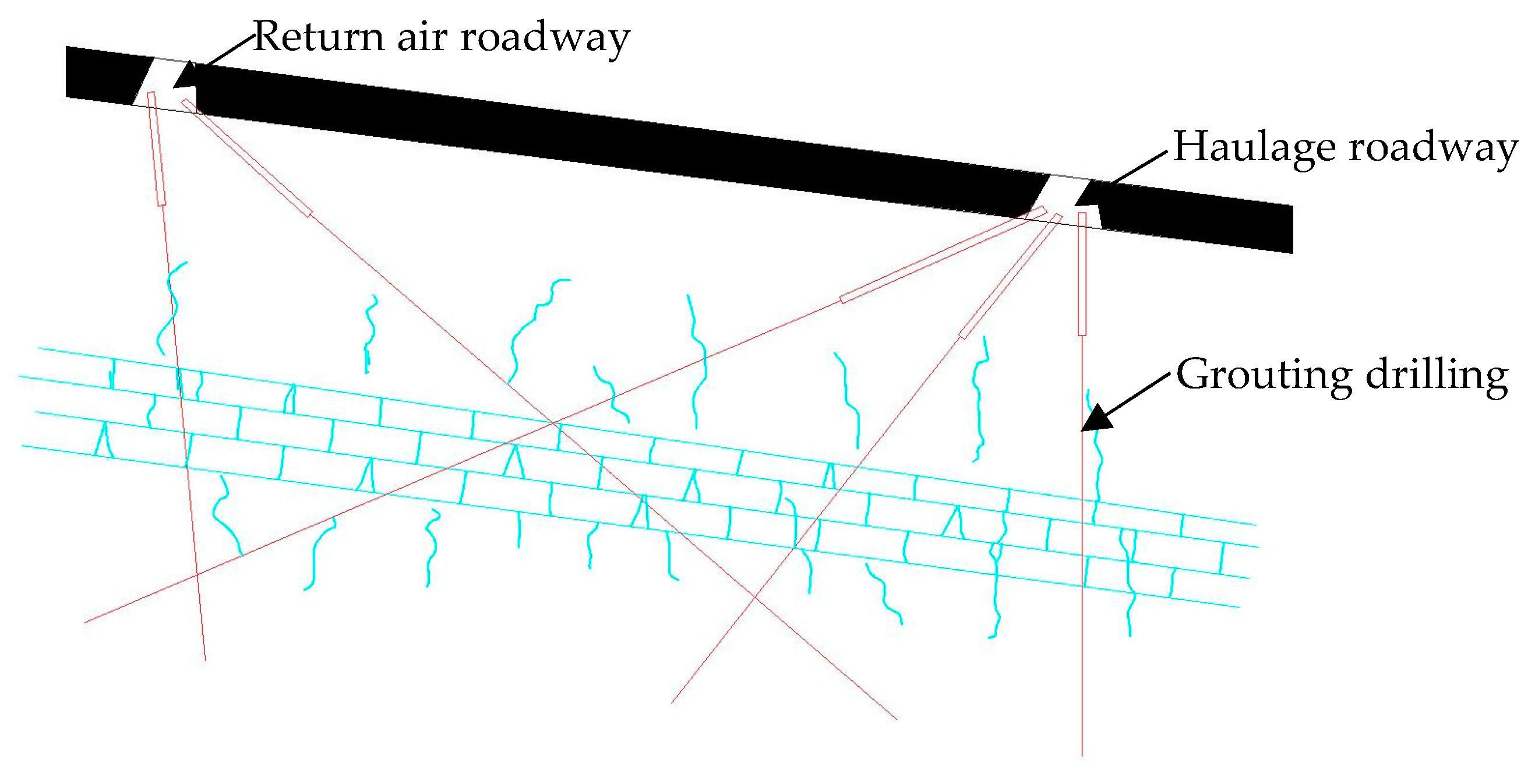
Generally, the cross-layer borehole grouting reinforcement method in mines employs a thin limestone aquifer within the floor failure depth range as the reconstruction object, which is the treatment target layer. An inclined or vertical borehole is utilized, and the internal leakage point and the final hole of the borehole are grouted for reinforcement (Figure 2). Once grouting is complete, the casing is filled with grout and permanently “embedded” in the bottom plate. As there are a substantial number of cross-layer casings in the underground cross-layer drilling treatment working face, the casings significantly reinforce the bottom layer, forming a “pipe pile” structure.
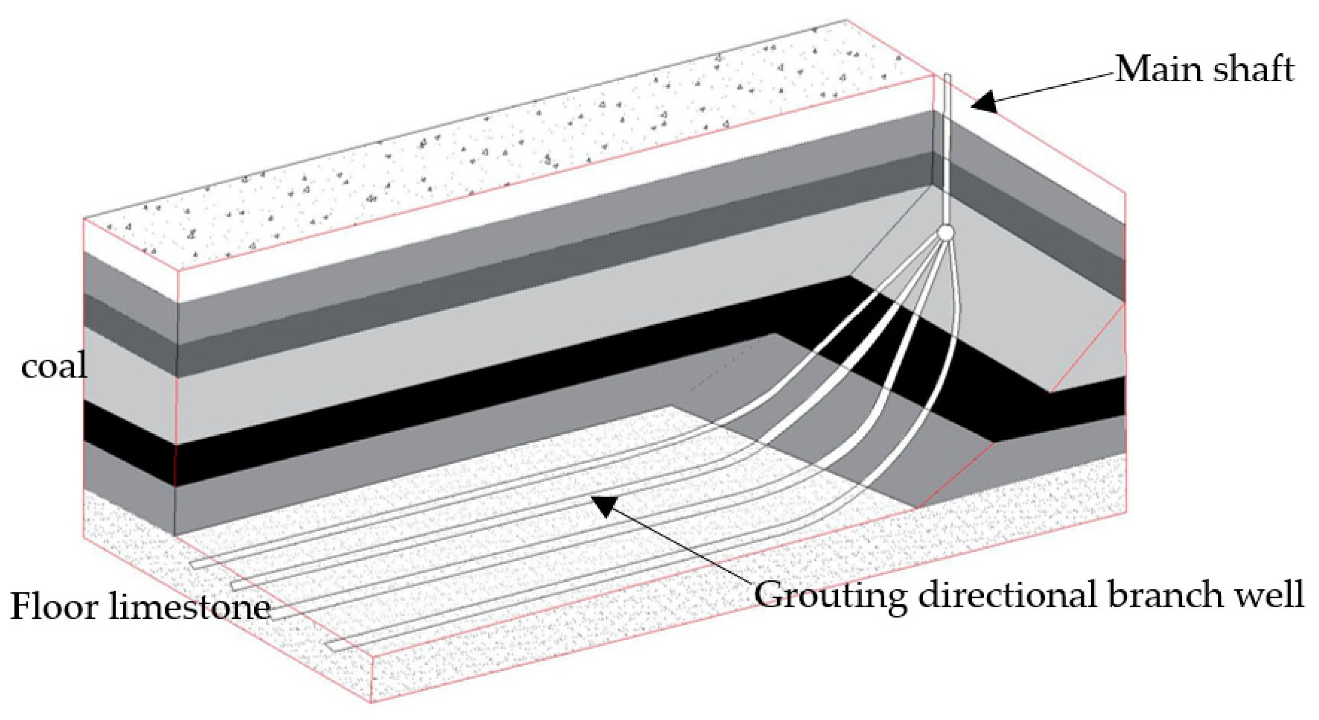
The layer beneath the floor failure zone and above the rising zone of the confined aquifer is typically utilized as the floor’s water-resisting layer. The water-resisting layer may not necessarily be completely destroyed during mining; however, it is still subject to the coupling effect of mining and the highly confined aquifer. The possibility of instability and failure of the layered composite aquiclude without regional reconstruction is higher under the coupling action of mining and water pressure. After regional treatment, the target layer (usually the main water-bearing limestone at the bottom of the Taiyuan Formation) is transformed into a water-resisting layer, and its strength is increased, forming a supporting plate or “key layer” capable of resisting the water pressure of the confined aquifer in the structure (Figure 3). This “key layer” alters the floor stress state of the working face and plays a protective role, particularly in the water-resisting layer section.
The mining-induced damage structure model of the grouting reinforcement floor is proposed based on the “pipe pile” structure formed by underground cross-layer grouting drilling and the “key stratum” structure formed by ground area treatment, reinforcement, and transformation of the aquifer. The model depicted in Figure 4 comprises the “pipe pile” and “key stratum” structures.

3. Model of “Pipe Pile” Reinforced by Cross-Layer Drilling and Grouting

In field practice, it has been observed that the fracture pattern of grouting casings indicates their ability to resist the deformation of rock strata. These casings can be compared to the structure of concrete steel tubes and micro piles, considering their flexural stiffness, axial, and normal strength. When the solidified slurry interacts with the casing and surrounding rock, it improves resistance to the deformation of the rock mass. Therefore, the impact of the slurry filling casing combination on the rock stratum of the coal seam floor cannot be disregarded [20,21].

3.1. Spatial Stress Characteristics of Casings under Distributed Abutment Pressure

To investigate the impact of grouted casings on rock deformation, we analyzed their action on the rock mass and their influence on the floor rock deformation mechanisms. The focus of the study was on the casing as the research object. We established a mechanical action model for grouting reinforcement casing in the floor rock stratum space under a distributed abutment pressure. Through theoretical analysis and verification of the action mechanism of the grout filling casings, we aimed to better understand how to use the grouting casings effectively [22,23].
Before grouting the reinforcement, the stress transfer in the rock or soil is conducted by friction and shear stress in the rock; after grouting reinforcement, the grouting pipe will become the main way for stress transfer. The casing, according to the mechanics of materials theory, is similar to a bar, whereby one end of the section (stable part of the casing) is bound to the fixed end of the other (free part of the casing), which is constrained by the distribution force below and the rock resistance of the casing. The free part of the casing has a direct effect on the floor rock mass deformation. When the resistance at the free end is less than the casing distribution, the casing will be bent upward, and deformation occurs. At this time, due to the bending capacity of the casing itself, the high rise can prevent the floor deformation effect.
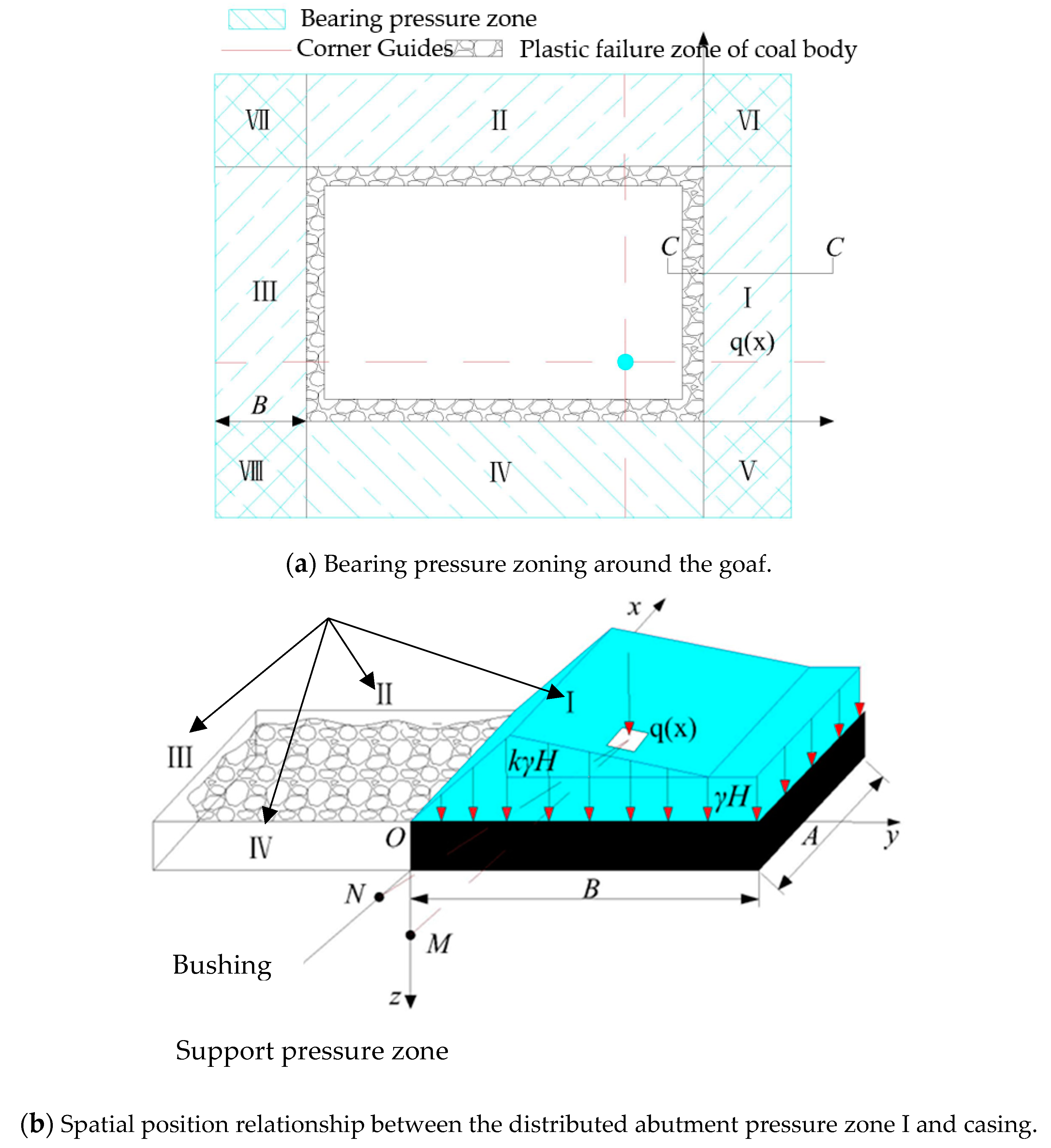
The goaf is formed by mining the working face, while the abutment pressure is distributed around the goaf and can be divided into eight rectangular areas (I–VIII), as depicted in Figure 5a. The areas I–IV are bearing pressure areas, and areas V–VIII are the distributed bearing pressure superposition, which is relatively small and negligible. A and B represent the width and length of the rectangular load, respectively. Furthermore, q(x) is a distributed load [13], and it is linearly distributed in the y-direction, while the x-direction belongs to the triangular distributed load. In a local coordinate system, this pressure is distributed as follows:
{ q ( x ) = k γ H ( 1 + y / β ) q ( x ) = γ H [ ( 1 k ) y / λ + k ] β y 0 0 y λ
the stress concentration factor is represented by k and γ denotes the average unit weight of the overlying strata in KN/m3. H represents the depth of burial in meters, while β refers to the distance from the coal pipe wall to the peak value of concentrated stress in meters. Moreover, λ indicates the distance from the peak value of concentrated stress to the stress boundary of the leading bearing, measured in meters.
Before mining, the casing is installed in the floor rock stratum, as shown in Figure 5b. After grouting and hole sealing, the grout, the casing, and the surrounding rock form a tightly coupled system, with the casing and rock stratum in the relationship of action and reaction. To analyze the casing deformation, one must solve the spatial stress on the point on the casing.

3.2. Stress Solution of Arbitrary Point on Casing in Space

There are acting and counteracting forces at the contact point between the surrounding rock and the casing. If the force at a point in the surrounding rock is available, the corresponding force at the point in the casing can be obtained. Stress analysis of the casing is conducted separately, as shown in Figure 6, and the spatial stress state of any point N on the casing is presented in Figure 6a. An oblique section is considered with an inclination angle of α, perpendicular to the normal casing’s bending plane. Sx, Sy, and Sz are the projected components of the total stress S on the coordinate axes of the oblique section. The oblique section projection of the sleeve and the force at a point on the sleeve are depicted in Figure 6b.
1.
Normal stress σ α at one point on the casing.
If the spatial stress, ( σ i j ) N   ( σ i j ) N = [ σ x σ x y σ x z σ y x σ y σ y z σ z x σ z y σ z ] , at N points is known, then, the normal stress σ α on the oblique section with an inclination angle α can be obtained as follows:
σ α = σ x μ 2 + σ y ν 2 + σ z ω 2 + 2 ( σ x y μ υ 2 + σ y z υ ω 2 + σ z x ω μ 2 ) = σ x n i n j
here μ ,   ν ,   ω are the direction cosines of the normal to the oblique section; n i ,   n j are index symbols, representing direction cosine.
2.
Shear stress τ α at one point on casing.
By computing the stress components S j = σ i j n i ( i , j = 1 , 2 , 3 ) and the total stress on the oblique section S 2 = S 1 2 + S 2 2 + S 3 2 , the shear stress τ α on the oblique section with inclination α can be obtained:
τ α 2 = S 2 σ α 2 τ α 2 = S 2 σ α 2

3.3. Mechanical Mechanism of Casing Filled with Slurry

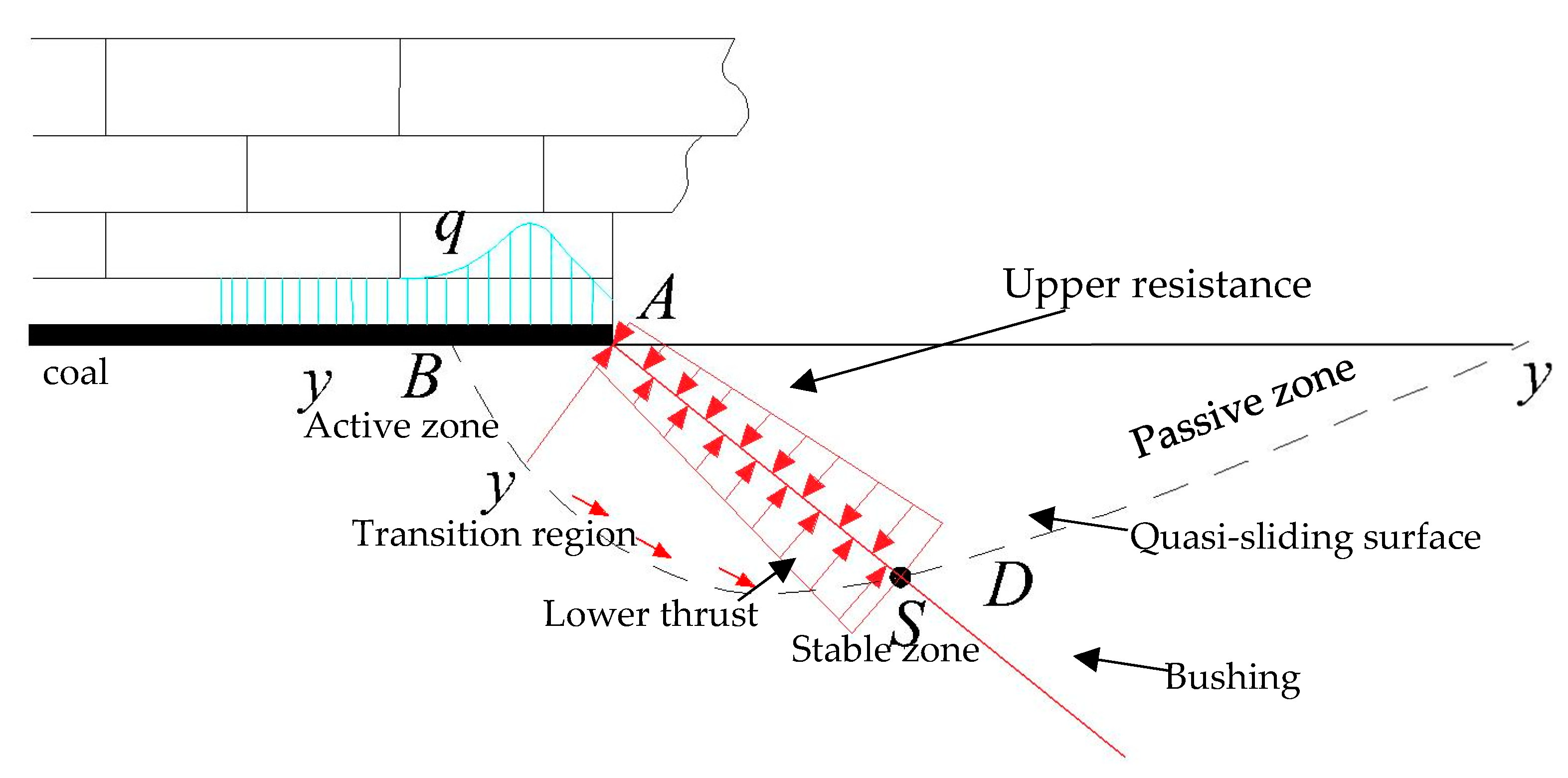
To analyze the mechanical mechanism of the grout-filled casing, we considered its bending stiffness. The formation of the floor failure zone after mining a working face results in significant deformation, which is closely related to the coal seam mining height, floor lithology, buried depth, rock integrity, and water pressure [24]. As the working face progresses, the coal mining process creates an abutment pressure zone, causing part of the floor rock mass to shift from the elastic to the plastic state, ultimately resulting in the floor failure zone. To further explore the impact of casing bending resistance on the rock stratum’s deformation, we analyzed the critical transient state of the elastic–plastic limit equilibrium of the floor rock mass. In this state, the plastic deformation of the floor rock mass is about to occur, and the elastic mechanical condition is satisfied. Drawing on relevant theories of mine pressure and rock mechanics, we demonstrated the failure form of the floor in Figure 7, wherein a quasi-failure sliding surface was formed at the transient state of elastic–plastic limit equilibrium [25,26].
Thus, the bending moment generated at the boundary point due to the resistance of the casing to the deformation of the grouting reinforcement body of the bottom plate is as follows:
M β ( x , y , z ) = 0 D m a x σ N [ ( D m a x z ) / cos α ] d / cos α   d z
here D m a x is the quasi-maximum failure depth without grouting reinforcement. Furthermore, d is the diameter of the casing, and α = 90 ° β . σ = M l / I z , where l is the distance between the longitudinal plane and the neutral layer and I z is the moment of inertia of the cross-section about the neutral axis.
The bending strength condition of the cannula is σ m a x = M m a x W [ σ ] . Here [ σ ] is the bending allowable stress of the grouting casing and W is the bending section coefficient of the grouting casing.
The maximum deflection at point O of the casing tip is calculated as a cantilever beam under distributed force:
ω 0 = 1 6 E I 0 D m a x ( σ N d cos α ) [ 2 D m a x + z cos α ] ( D m a x z ) 2 / ( cos α ) 2 d z
therefore, the maximum vertical deformation of the bottom plate borne by the casing is ω m a x = ω 0 cos β .
Under the condition of bending stress intensity, the casing can control the deformation of the bottom plate, where the deformation of the bottom plate is ω m a x = ω 0 cos β .

4. “Key Layer” Model of Ground Area Governance

According to the key layer theory for water inrush from the floor, the high-strength rock strata in the complete zone of the floor after grouting reinforcement and regional treatment can be defined as the “key layer of water resistance.” The water inrush from the floor depends on the water resistance of this key layer. Therefore, based on the structural characteristics of the rock stratum reinforced by the floor and the influence of deep mining geostress, the key waterproof layer is generalized into a thin plate under positive and negative loads using the key layer theory and elastic thin plate theory. The positive load includes the dead weight of the key waterproof layer and the dead weight of the upper floor strata, and the overburden collapse strata, which plays a role in restraining the deformation and damage of the floor or in resisting water pressure. The negative load is the water pressure of the confined water, which contributes to the deformation and damage of the key waterproof layer of the floor [27].

4.1. Mechanical Model of “Key Waterproof Layer”

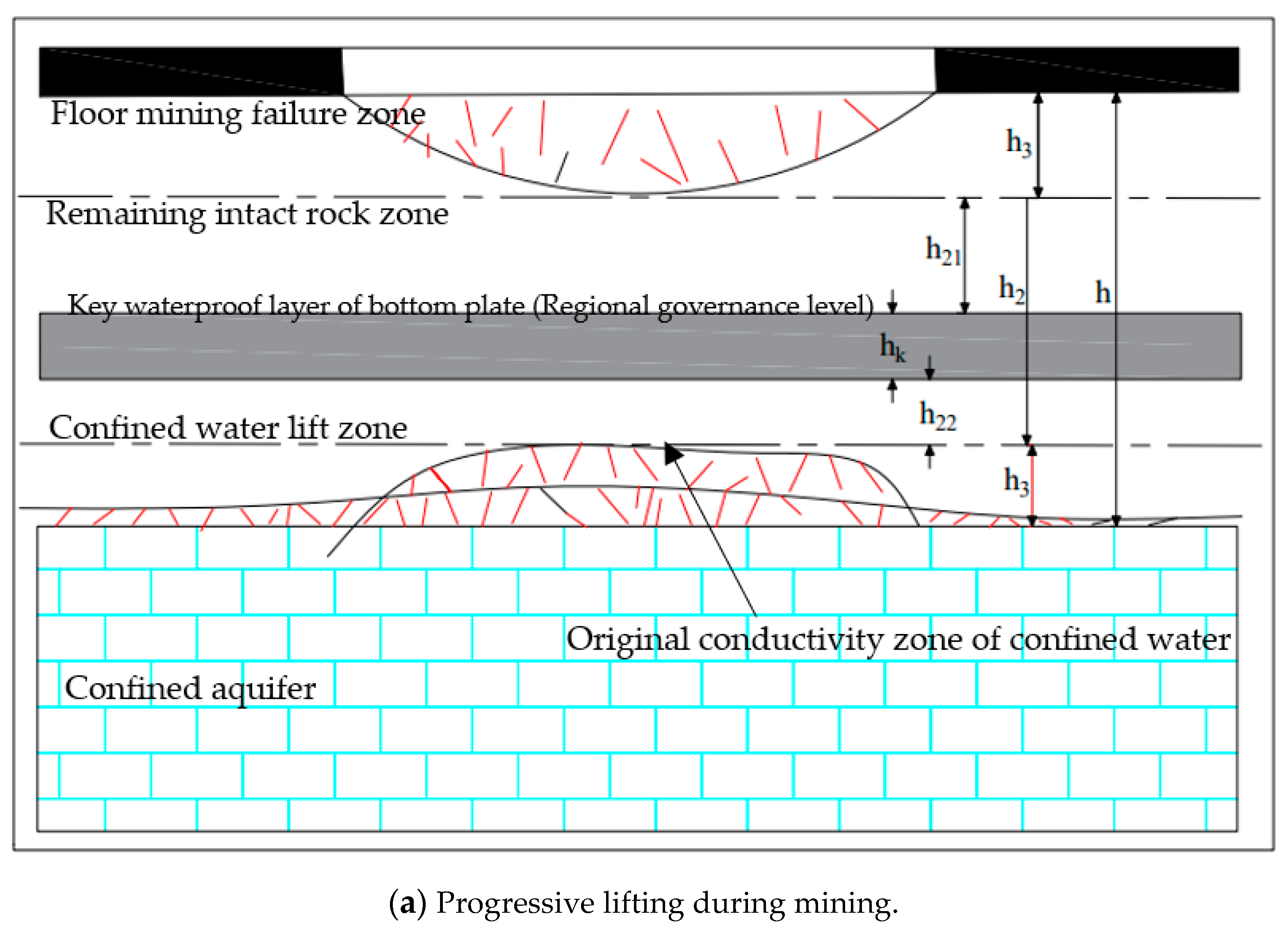
Prior to coal seam mining, hydraulic conductivity cracks of varying heights develop upwards on the top interface of the floor-confined aquifer. This is the original hydraulic conductivity of the confined water. Post-mining, the surrounding rock of the stope is deformed and destroyed, resulting in a floor mining failure zone with a depth of h1. Simultaneously, due to the combined effects of mining pressure and confined water pressure, the confined water on the floor is further directed upward along the original water diversion fissure to create a progressive uplift zone of confined water. The total height of the original elevation zone of confined water and the progressive uplift zone of confined water is known as the confined water uplift zone, with a height of h3, as illustrated in Figure 8a. When the mining damage zone of the floor connects with the confined water uplift zone, water inrush from the floor of the working face occurs, and vice versa. There is an undamaged rock zone left between the floor mining failure zone and the confined water guide zone [28,29]. Moreover, the effective water-resisting layer thickness of the floor changes from h before mining to h2, h 2 = h ( h 1 + h 3 ) = h 21 + h k + h 22 , where hk is the thickness of the key waterproof layer of the bottom plate. As the working face continues to advance, the mining damage depth of the floor further increases and peaks at h 1 ( h 1 > h 1 ) , where h 21 is reduced to h 21 . Similarly, under the combined action of the mining pressure and confined water pressure, the confined water on the floor will continue to rise gradually and finally move to the lower part of the key water-resisting layer on the floor. Consequently, the height of the confined water guide zone will become h 3 , h 3   =   h 3 + h 22 . The effective water-resisting layer thickness of the floor is reduced to h 2 , h 2 = h 21 + h k , as depicted in Figure 8b.
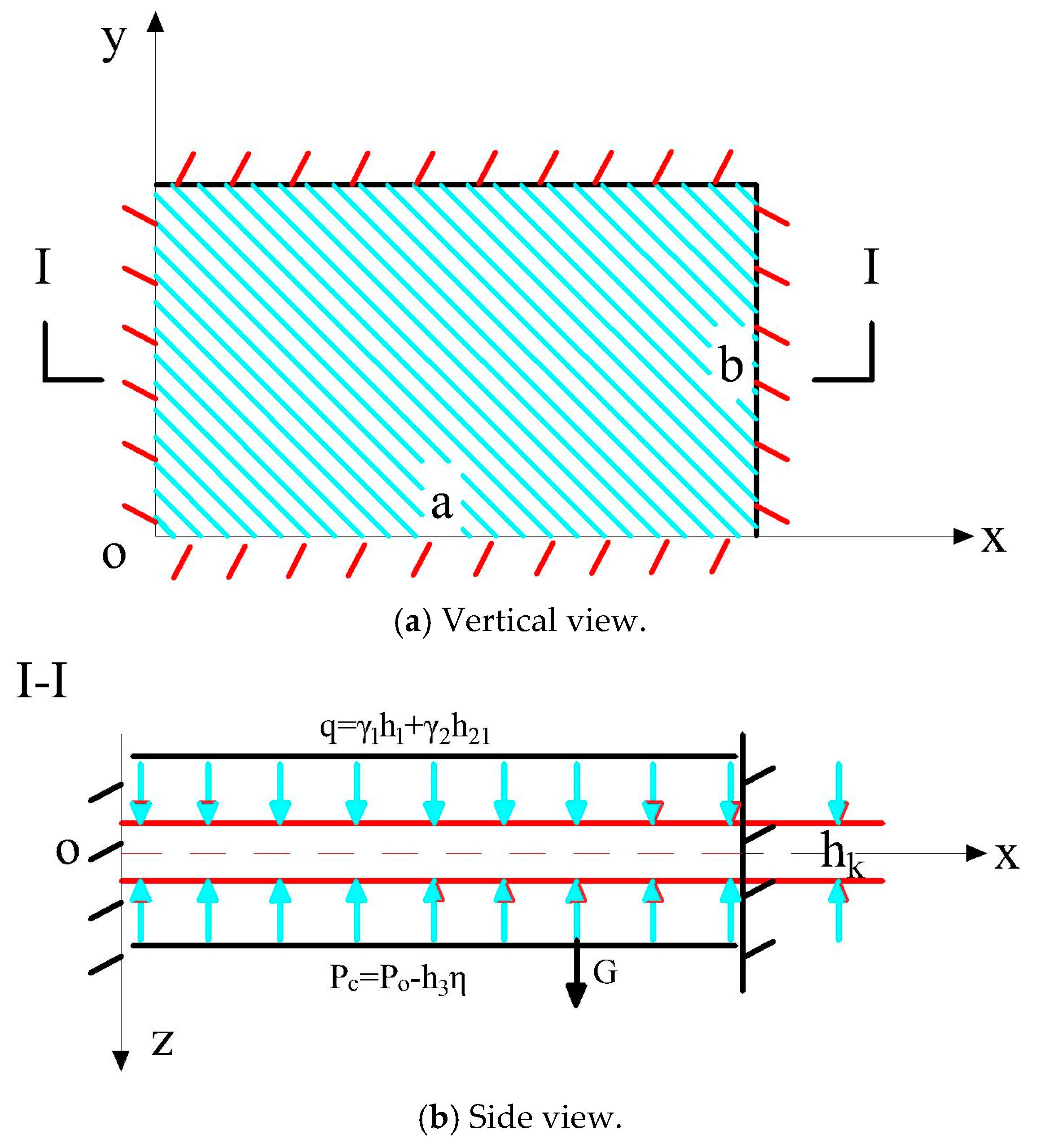
Whether water inrush occurs after reinforcing and treating the bottom plate depends on the stability of the key water-resisting layer and its resistance to the progressive hydraulic conductivity of the bottom plate. To analyze the water-resisting performance of the key water-resisting layer, a mechanical model was established, as shown in Figure 9. The average elastic modulus of the mining damage zone of the bottom plate is E1, and the unit weight is γ1, with a Poisson’s ratio of μ1. The average elastic modulus of the remaining intact rock zone on the floor is E2, with a unit weight of γ2 and Poisson’s ratio of μ2. The average elastic modulus of the bottom plate-confined water lifting zone is E3, with a unit weight of γ3 and Poisson’s ratio of μ3. The average elastic modulus of the key waterproof layer of the bottom plate is Ek, with a unit weight of γk and Poisson’s ratio of μk. The thickness of the remaining intact rock layer above the key waterproof layer of the floor is h21, and the thickness of the remaining intact rock layer below is h22, where the confined water has not been gradually led to the lower part of the key water-resisting layer. The requirements of h 21 + h k + h 22 = h 2 are depicted in Figure 9a.
Based on the key layer theory and the elastic thin plate theory, the key layer of the bottom waterproof layer can be simplified as a thin rectangular plate with four fixed sides. The plate has a length of “a” in the x-direction, which represents the working face inclination, and a length of “b” in the y-direction, which represents the advancing direction of the working face [29,30].
Based on the theory of rock beams or thin plates, the upper part of the floor strata is in an unloading state following coal mining. Meanwhile, the lower part of the floor strata is bent upward due to the water pressure of the aquifer, causing the confined water lifting zone to be moved into a compression failure state. The floor mining failure zone, h1, is calculated without considering the load effect of the roof caving rock mass on the key layer of the floor waterproof. The remaining intact rock layer above the key waterproof layer of the floor, h21, is considered as the vertical load acting on the upper surface of the key waterproof layer of the bottom plate, q = γ 1 h 1 + γ 1 h 21 . Under the combined effects of mining and confined water pressures, the water in the confined water leading fracture zone moves upwards along the fracture under changing confining pressures. If the elastic modulus of the upper layer encountered by the leading water pressure is much lower than that of the lower layer, the leading water pressure will extend through the interface to the upper layer, as shown in Figure 8a. Otherwise, the fracture will stop at the interface, as shown in Figure 8b. The progressive hydraulic conductivity terminates at the lower part of the key water-resisting layer of the floor, for which the elastic modulus is much greater than that of the lower layer. There is head loss during the upward diversion of confined water. This head loss, denoted as η, is closely related to the permeability coefficient k of the rock stratum below the floor. The lower the permeability of the rock stratum, the greater the head energy it reduces, resulting in a decrease in the head loss with an increase in the permeability coefficient of the rock stratum [31,32]. The progressive hydraulic pressure in the confined water lifting zone is   p c , where   p c = p o h 3 η (   p o is the water pressure of the floor-confined aquifer). Therefore, when the confined water is gradually guided to the lower part of the key waterproof layer of the bottom plate, the progressive leading water pressure is   p c = p o h 3 η or   p c = p o (   h 3 + h 22 ) η .
Based on the elastic thin plate theory, the expression for the deflection of the key waterproof layer of the bottom plate, which meets the requirements of fixed support on all four sides, is as follows:
ω = A sin 2 π x a sin 2 π y b
following the principle of minimum potential energy, the coefficient A of the deflection function of the key waterproof layer of the bottom plate can be obtained as follows:
A = γ 1 h 1 + γ 2 h 21 + γ k h k p c D π 4 ( 3 a 4 + 2 a 2 b 2 + 3 b 4 )
where D is the bending stiffness of the key waterproof layer of the bottom plate. D = E k h k 3 / 12 ( 1 μ k 2 ) .
Moreover, the deflection function of the key waterproof layer of the bottom plate ω is as follows:
ω = γ 1 h 1 + γ 2 h 21 + γ k h k p c D π 4 ( 3 a 4 + 2 a 2 b 2 + 3 b 4 ) sin 2 π x a sin 2 π y b

4.2. Hydraulic Criteria for Water Inrush of “Key Water-Resisting Layer”

By substituting Equation (8) into the functional relationship between stress and deflection of an elastic rectangular thin plate, the stress of the key waterproof layer of the coal seam floor can be obtained as follows:
σ x = E k z A 1 μ k 2 ( 2 π 2 a 2 cos 2 π x a sin 2 π y b + μ k 2 π 2 b 2 sin 2 π x a cos 2 π y b ) σ x = E k z A 1 μ k 2 ( 2 π 2 b 2 cos 2 π y b sin 2 π x a + μ k 2 π 2 a 2 sin 2 π y b cos 2 π x a ) τ x y = E k z A 1 μ k 2 ( π 2 a b sin 2 π x a sin 2 π y b ) 0 x a , 0 y b , z = μ k / 2
by substituting Equation (9) into the calculation formula for principal stress, the expression for the principal stress at any point on the key waterproof layer of the coal seam floor can be obtained as follows:
σ 1 , σ 3 = σ x + σ y 2 ± ( σ x σ y 2 ) 2 + τ x y 2 = B 1 ± B 2 Here ,   B 1 = E k z A 1 μ k 2 ( π 2 a 2 cos 2 π x a sin 2 π y b + π 2 b 2 sin 2 π x a cos 2 π y b ) B 2 = E k | A | 1 + μ k ( π 2 a 2 cos 2 π x a sin 2 π y b π 2 b 2 sin 2 π x a cos 2 π y b ) 2 + ( π 2 a b sin 2 π x a sin 2 π y b ) 2
When rock mass yield failure occurs under multidirectional stress, the Mohr–Coulomb yield criterion is obeyed. This means that when yield failure occurs at a point on the waterproof key layer of the coal seam floor, the relationship is satisfied:
σ 1 K σ 3 = R c K = ( 1 + sin φ 0 ) / ( 1 sin φ 0 )
here φ0 is the internal friction angle, Rc is the uniaxial compressive strength of the key waterproof layer of the bottom plate, R c = 2 C cos φ / ( 1 sin φ ) , and C is cohesion.
Let   f ( x , y ) = σ 1 K σ 3 R c
Using the function ratio of f (x, y), we can determine whether a specific point (x0, y0) on the crucial waterproof layer of the coal seam floor has yield failure, and we can also predict the water inrush from the coal seam floor. We can express f (x, y) as a substitute of Formula (10) into Formula (12):
f x , y = E k μ k 2 R c 1 K A 1 μ k π 2 a 2 cos 2 π x a sin 2 π y b + π 2 b 2 sin 2 π x a cos 2 π y b + ( 1 + K ) A 1 μ k ( π 2 a 2 cos 2 π x a sin 2 π y b π 2 b 2 sin 2 π x a cos 2 π y b ) 2 + ( π 2 a b sin 2 π x a sin 2 π y b ) 2
During the mining of the working face, the stress state of the floor rock stratum undergoes changes. Upward bending deformation failure of the key waterproof layer can cause water inrush from the working face floor. This occurs when the deflection is negative (ω < 0) and its coefficient A < 0. Therefore, E K h k ( 1 K ) A / R C ( 1 μ K ) and E K h k ( 1 + K ) A / R C ( 1 + μ K ) in function f (x, y) are functions that are independent of coordinates x and y, E K h k A / R C = 1 and E K h k A / R C = 1 . Typically, the maximum value of the function f (x, y) is located at the midpoint of the long side of the key waterproof layer of the bottom plate. This point has coordinates (x = a/2, y = 0, b). Therefore, we substituted them into Formula (13) to obtain:
f ( x 0 , y 0 ) = π 2 E k h k 2 b 2 R C [ ( 1 K ) A 1 μ k + ( 1 + K ) | A | 1 + μ k ] = 12 ( K μ k ) R c h k 2 p c γ 1 h 1 + γ 2 h 21 + γ k h k π 4 b 2 ( 3 a 4 + 2 a 2 b 2 + 3 b 4 )
Equation (13) presents the hydraulic criterion for the yield failure of the key waterproof layer in the coal seam floor. When f (x0, y0) > 1, the points (x0, y0) on the key waterproof layer of the coal seam floor are in a state of yield failure, resulting in water inrush from the floor. When f (x0, y0) = 1, the point (x0, y0) on the key waterproof layer of the coal seam floor is in a critical state of yield failure, and water inrush from the floor will occur.

4.3. Analysis of Water Resistance Performance of “Key Water Resistance Layer”

Let f (x0, y0) = 1, we can get from Formula (14):
P c m = π 2 b 2 R c h k 2 12 ( K μ k ) ( 3 a 4 + 2 a 2 b 2 + 3 b 4 ) + γ 1 h 1 + γ 2 h 21 + γ k h k
Equation (15) is the expression of the maximum progressive hydraulic pressure P c m exhibited by the key waterproof layer of the coal seam floor. When P c m > P c , the key waterproof layer of the floor of the mining face is stable, suggesting no water inrush from the floor; furthermore, when P c m = P c , the key water-resisting layer of the floor of the mining face is critically stable, suggesting the occurrence of water inrush from the floor.
Next, we introduced the strength characteristic parameter characterizing the resistance to yield failure of the key waterproof layer of the floor β. The size effect parameters λ, let β = R c 12 ( K μ k ) and λ = π 2 b 2 ( 3 a 4 + 2 a 2 b 2 + 3 b 4 ) . Thus, Formula (15) can be expressed as:
P c m = β λ h k 2 + γ 1 h 1 + γ 2 h 21 + γ k h k
using Formula (16), we can conduct further analysis on the size effect and strength characteristic parameters of the main waterproof layer of the working face floor, which can aid in predicting and preventing water inrush more effectively. This provides a strong theoretical foundation for improving the waterproof performance of the working face floor.

4.4. Numerical Analysis of Crack Propagation Law of a Coupling Model of “Key Layer” in Regional Governance

4.4.1. Model Construction

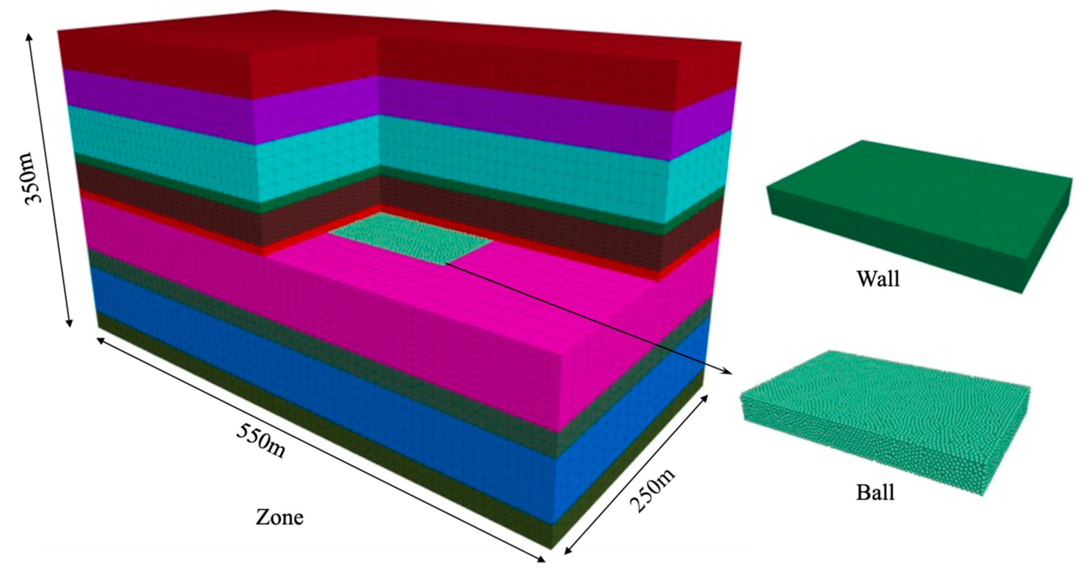
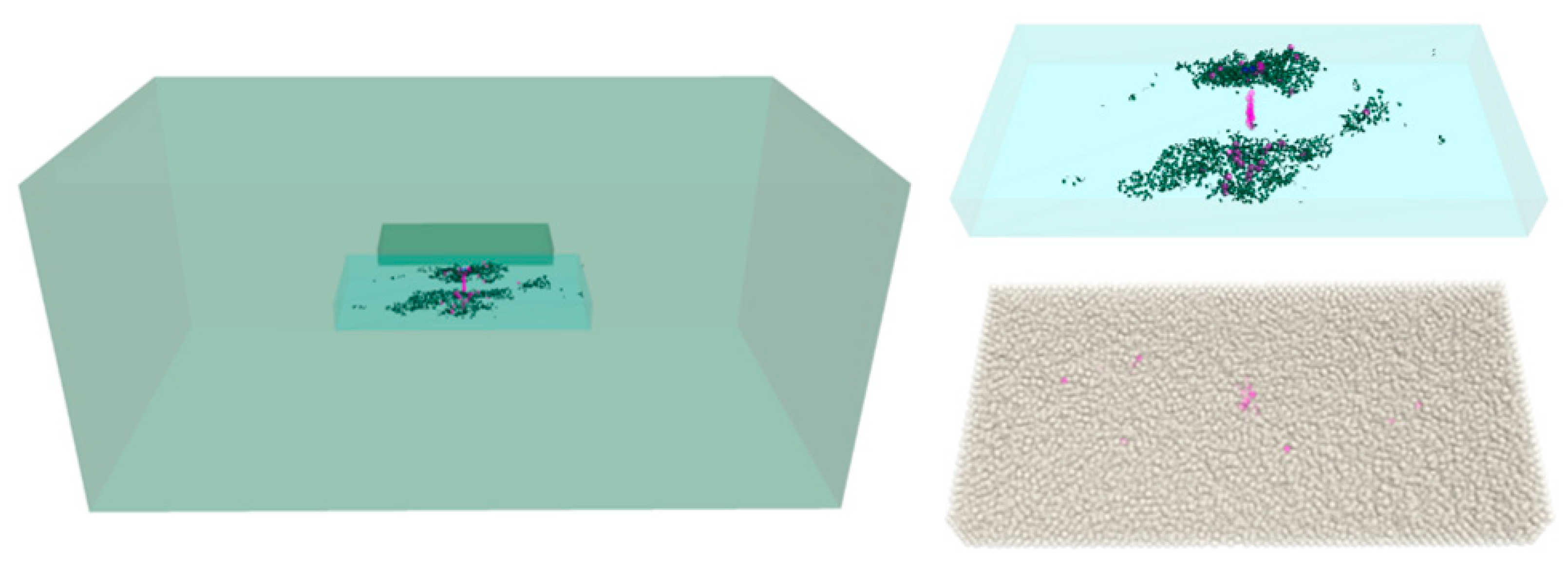
Based on the mining and geological information of the 220106 working face, the continuous media model of the simulation was established. To verify the mining damage model of the slurry reinforced floor and the structural model of the “key layer” formed by the regional management, it planned to use the finite element simulation for the mining face and the damaged area of the floor and discrete element simulation for the slurry reinforced layer, to build a continuous finite-element-discrete element coupled numerical simulation model.
The compressive strength value in the unconfined uniaxial compression experiment of the combined grout-body-rock unit in this study is theoretically larger than that of the grouted body part. Therefore, the FLAC3D finite element modeling was used to calculate the rock part of the unit, and the PFC discrete element particle flow modeling was used to calculate the grouted body part. The two parts are coupled by wall-zone coupling, which is an edge–edge coupling method.
Firstly, the floor area under evaluation was identified, and a blank model was assigned to establish the discrete elements. Next, a sphere with random distribution but specified porosity was established in the empty model area, and a dispersion and uniformity model was provided. Then, the mesoscopic parameters of the parallel bonding model are calibrated based on the unit experiment, and the discrete particle units are cemented. At this point, the discrete element model generated by PFC can be considered to have the same macroscopic properties as the continuum model established by FLAC3D. Finally, the internal force generated during the establishment of the discrete model was cleared to complete the establishment of the coupling model. Figure 10 shows the model diagram, and Table 1 presents the physical and mechanical parameters of the rock.
The continuous medium region is adopted as the Mohr–Coulomb intrinsic model. The discrete model is adopted as the parallel bonded intrinsic model, and the prefabricated cracks in the study area of the bottom plate are smooth nodal models. The meta-fine view parameters are shown in Table 1; the medium numerical parameters are shown in Table 2. The boundary condition is to limit the displacement in the vertical direction at the bottom and horizontal direction around, while the stress boundary is applied at the top and the values are calculated according to the burial depth.

4.4.2. Simulation Scheme and Result Analysis

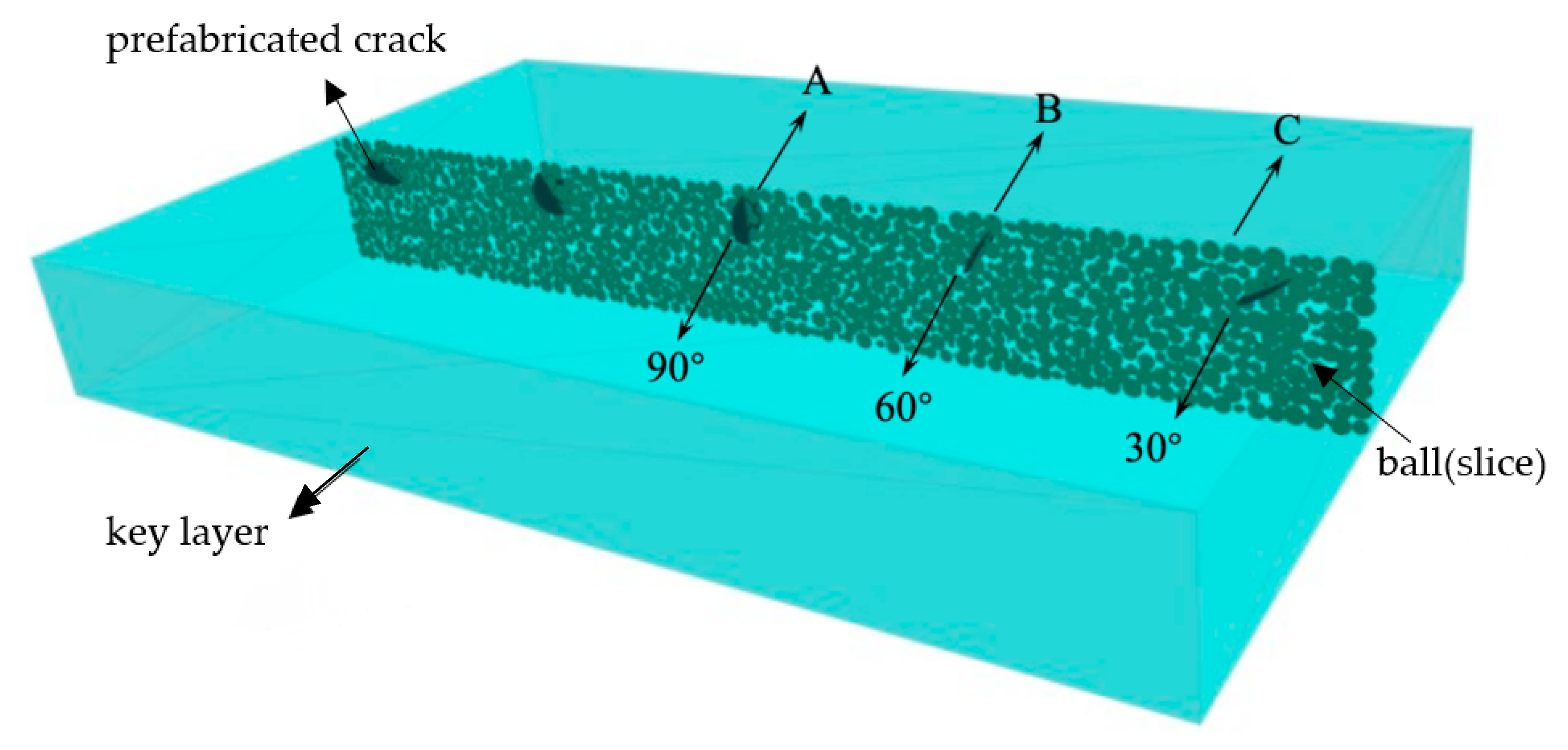
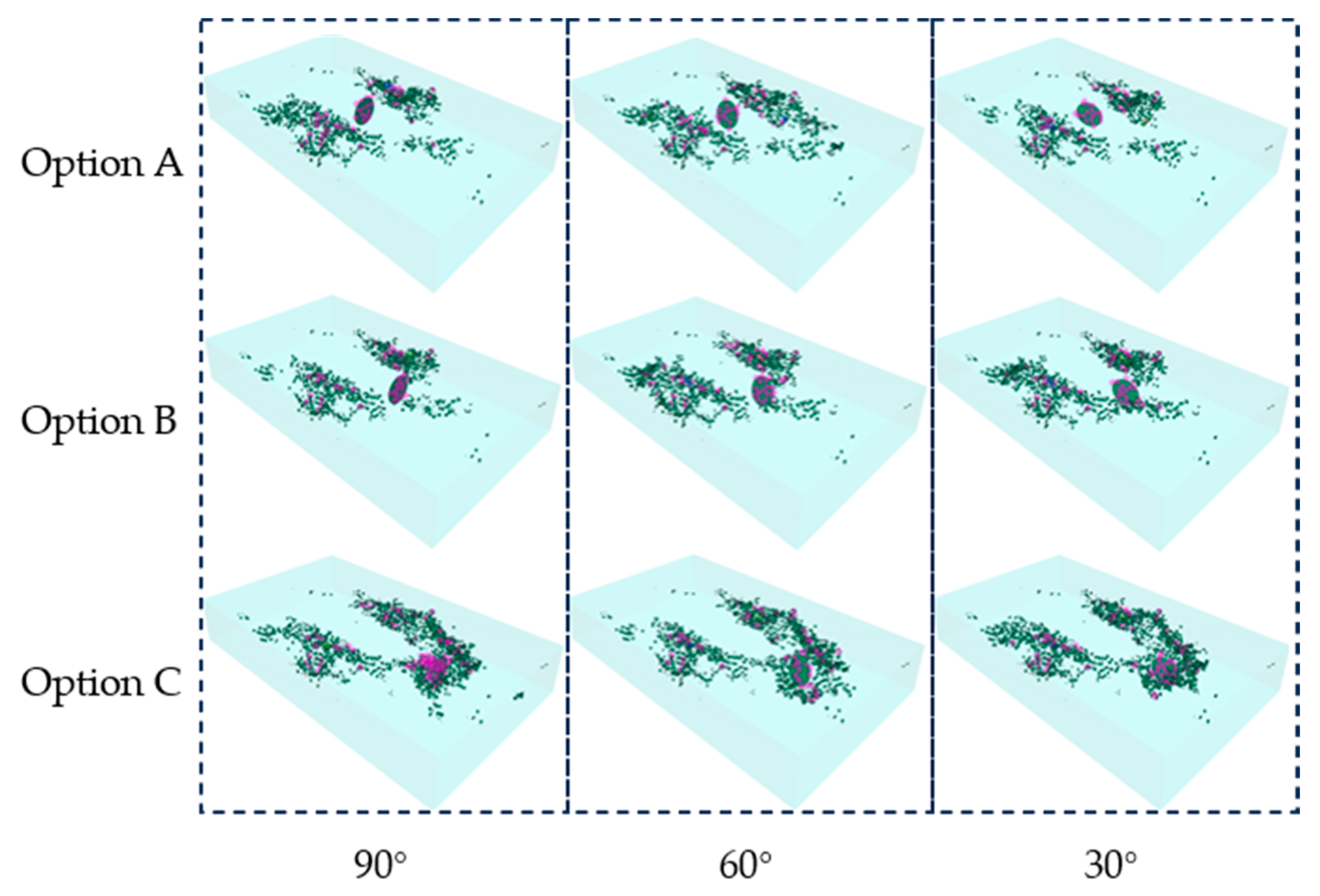
This numerical simulation focuses on the impact of a fracture at different positions by reducing the research angle to a single factor, which is the dip angle. The shape of the crack is linear in two dimensions but circular in FLAC3D and PFC3D, as illustrated in Figure 11, which displays the distribution of the dip angle and position of the crack. The simulation involves calculating three inclinations (30°, 60°, and 90°) at three positions, A, B, and C, in Figure 11. Due to symmetry, the other two positions do not require calculation. There are a total of nine schemes.
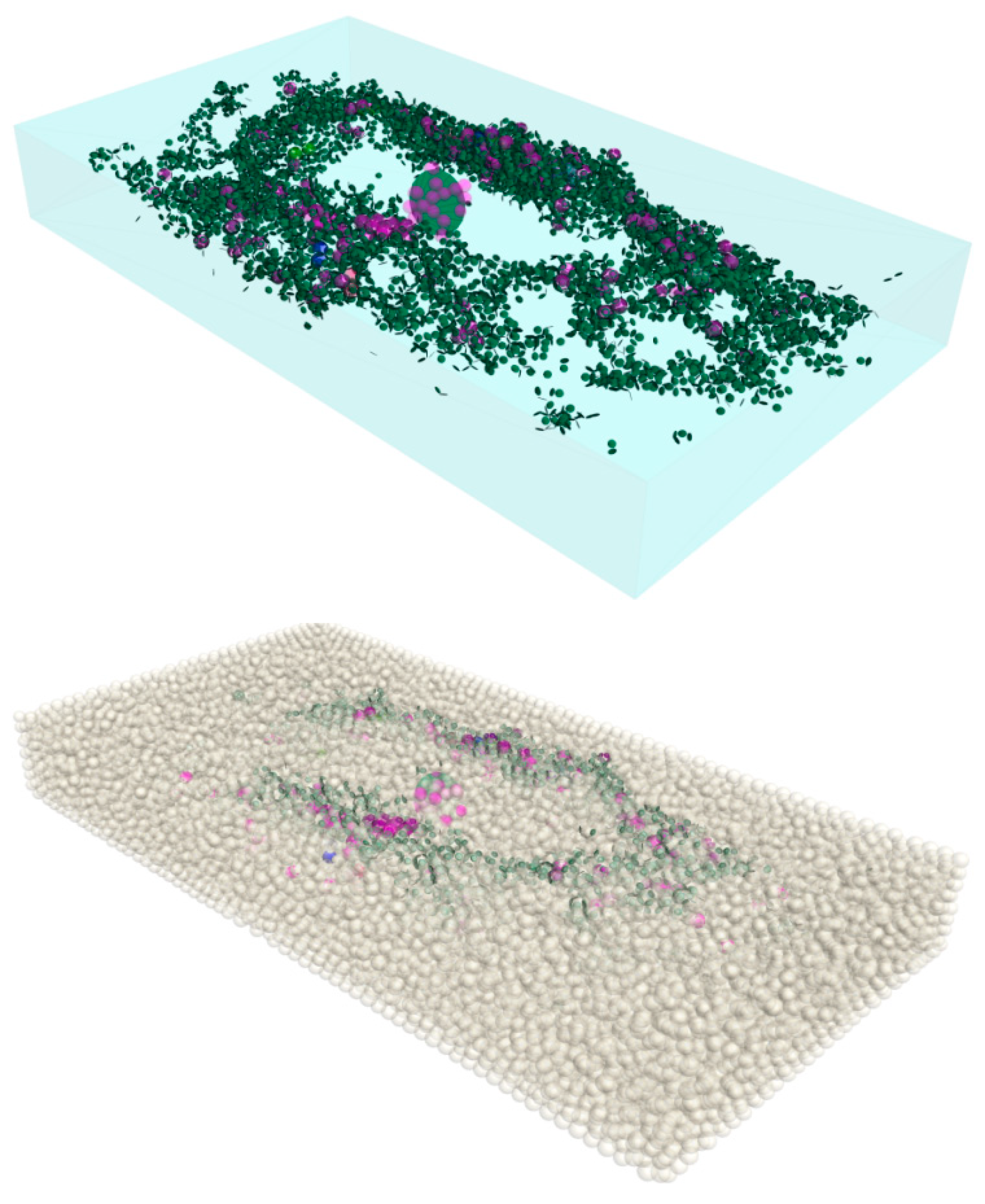
Figure 12 shows the calculation results for the case where the crack is located in the center and the dip angle is 60° after regional treatment. The transparent part represents the wall, depicting the geometric dimensions and location characteristics of the discrete element. The green disc is the microfracture produced by mining. The purple sphere in the upper and lower figures represents the above block, and the white translucent is the original block.
After the regional treatment, the water pressure of the lower confined aquifer is reduced, and the number of new blocks is very small, accounting for approximately 0.04% of the original block. This indicates that water pressure-induced damage to the aquifer can be effectively reduced. The distribution of fractures and blocks is consistent in space, mainly distributed in a wide area outside the goaf, in addition to the original fracture area. This is because after the coal body is mined, the stress is transferred to the outside. The center of the study area is similar to the bending of a thin plate, resulting in high tensile stress and the generation of horizontal tensile stress, reducing the confining pressure and the rise of axial pressure, causing shear failure [33,34,35]. However, no large-scale cracks occurred. Moreover, the generation of cracks is concentrated in the top area of the study. As the buried depth increases, the horizontal stress state gradually changes to compression, making it more difficult for shear failure to occur. This further verifies the previous analysis. The angle of the crack significantly influences compression and shear failure, although the effect is not obvious when the two main stresses in the horizontal direction decrease. Finally, it is worth noting that the original stress state is three-dimensional compression; however, the tensile stress is generated in the central region, where the effect is less pronounced.
Figure 13 depicts the production of new cracks and the expansion of the prefabricated cracks following regional treatment, along with the spatial correlation between the distribution of new blocks and cracks. Prior to treatment, there are numerous microfractures that connect vertically and form water diversion channels. Therefore, water inrush may occur even if the overall aquiclude is not significantly damaged. There is little difference between the different scenarios, as shown in Figure 14, which only shows the scenario where the crack is located in the middle and when the inclination angle is 60°.
After comparing the simulation results of the different schemes, it became evident that all the new fractures emerging in the spatial distribution were located where the goaf’s vertical projection extends along with the upper part of the study area. As such, they will not create a possible water channel with the underlying aquifer [36,37]. A longitudinal comparison shows that the new crack initiation increases significantly as the prefabricated crack position moves outward, regardless of the angle. According to the above, the closer the distance from the mining area, the more the resulting tensile stress is generated in the horizontal direction, which means the horizontal main stress decreases. The center of the mining area down the vertical projection position is no damage, and damage occurs in the area of the projection as the mining area extends. This is due to two reasons. One is the reduction in the horizontal principal stress, and the other is the increase in the principal stress caused by the stress transfer. When the precast cracks are located in the area of this extension (location C), it makes the strength of the local rock mass decrease compared to the other areas, which causes a further extension of the precast cracks. Corresponding to this, the new block is also more distributed in this region.
Horizontally, when the prefabricated crack is at positions A and B, the crack hardly expands, and the change in angle has little impact on the growth of the crack. Therefore, if the primary fractures of the aquifer in the study area are at these locations, the impact on water inrush is minimal. However, at location C, even after regional treatment, the cracks have expanded, making it easy to form a fracture connection and water channel, explaining why water inrush still occurs after the floor grouting.
Numerical calculation results reveal that the change in the crack angle affects crack propagation differently. For example, at 90°, the crack propagation and the number of blocks are the largest, followed by 30°, while 60° yields the smallest results. This calculation result deviates from conventional mechanical analysis due to the difference between the stress rise area and location C of the crack. In other words, the crack’s vertical stress is no longer the maximum principal stress.

5. Microseismic Response Characteristics of Floor Grouting Reinforcement

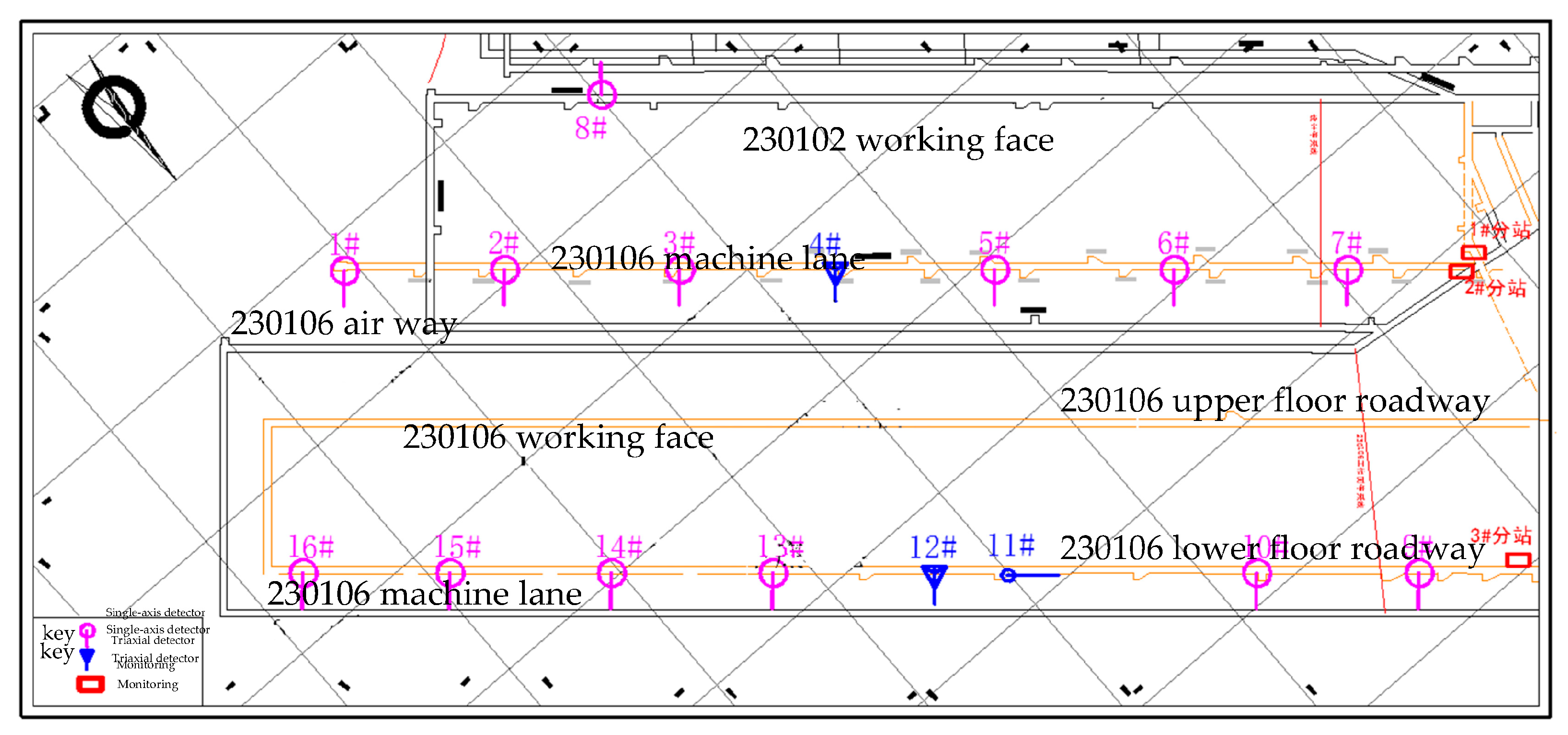
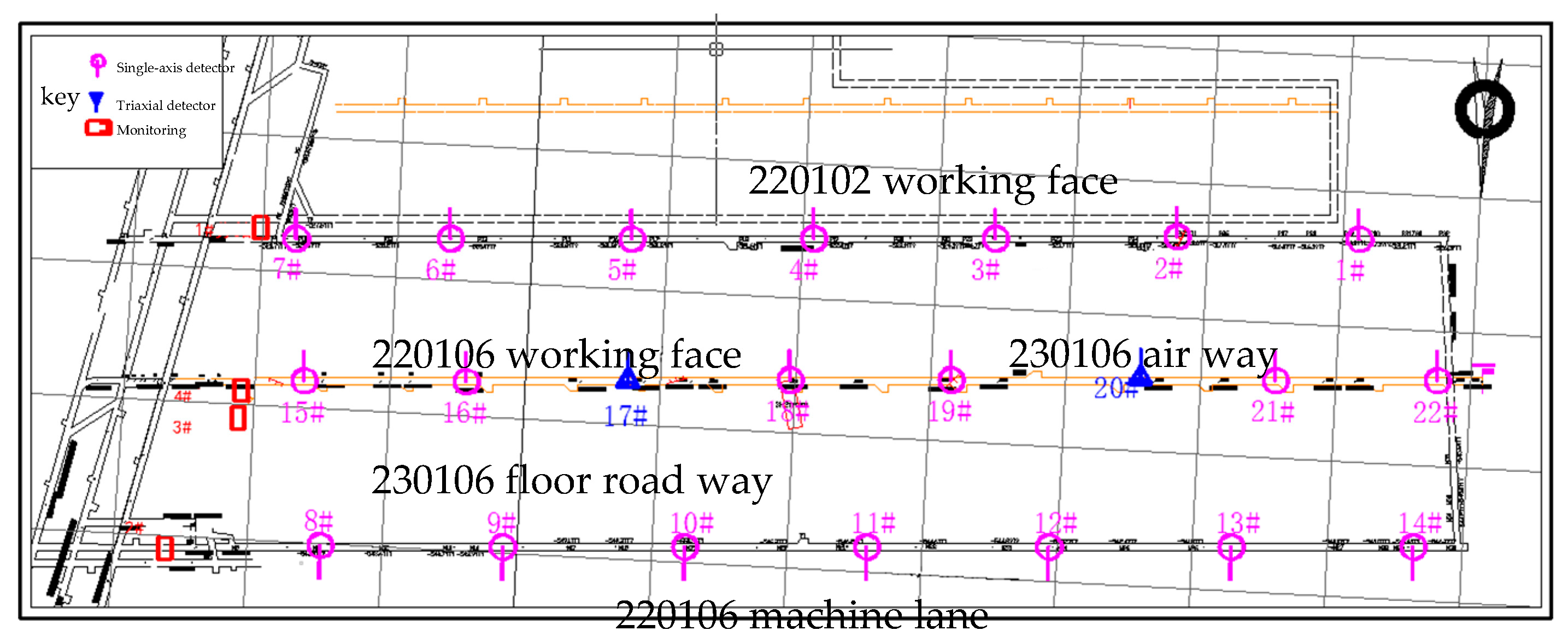
To further verify the effectiveness of the grouting reinforcement project, the Xinji No. 2 Coal Mine utilized the “point and plane” microseismic monitoring array for the 230102 working face (as depicted in Figure 15) and the “line and line” microseismic monitoring array for the 220106 working face (as depicted in Figure 16). The grouting reinforcement’s effectiveness was evaluated through the microseismic statistical law of both working faces.
From the perspective of the structure resulting from the grouting reinforcement, the 230102 working face underwent underground drilling and grouting, forming a “pipe pile” structure that was scattered and discontinuous after the grouting tool casing and slurry consolidated in the rock stratum. This structure can only control the damage to the floor within a certain range of its location. However, the 220106 working face underwent regional treatment and opted for bedding drilling and grouting. This formed a water-resistant “key layer” structure that has fully filled the deep karst fissures and is distributed along the layer. This structure can protect the floor on a large scale. The structural differences in the limestone on the floor of the two working faces result in significant differences in the microseismic response characteristics (as indicated in Table 3).
Generally, the number of microseismic events in the limestone of the Taiyuan Formation is significantly higher in the 230102 working face than in the floor of the 220106 working face. However, during the entire monitoring process, only group C3 II microearthquake events were detected in the 230102 working face, which was drilled and grouted through the layer, while group C3 II microearthquake events were not detected in the 220106 working face, which had undergone regional treatment. This indicates that the floor disturbance depth of the 230102 working face during mining was greater than that of the 220106 working face.
In the bottom of the Taiyuan group, the limestone contains shallow water layer upon layer, the 230102 face was monitored for the seismic events of 9379, while the 230102 working face was monitored for the seismic events of 17,387. When reinforcing the bottom slab with grout, the 230102 work of the Taiyuan group limestone C3 I, 1967 occurred, whereas only 659 occurred in the 220106 working face floor C3 I group. Only the 230102 face C3 II group of microseismic events, after the regional governance of 220106 working face, has not detected the C3 II group of microseismic events. The microseismic events of the 230102 working face of the Taiyuan group limestone are greater than the number in the 220106 working face floor event development, from the perspective of grout diffusion, the 220106 working face of regional governance can fill the deep karst fissure. In the floor area of the grouting governance, the Taiyuan group of karst fissures was effectively suppressed, and floor grouting reinforcement was only partially blocked, causing a mining disturbance and an obvious difference in the frequency of the microseismic events development.
Furthermore, the microseismic system of the 230102 working face was monitored from 8 July 2020 to 4 April 2021, with a total of 270 days being monitored and 52,430 effective microseismic events recorded, with an average of 200 per day. The microseismic system of the 220106 working face was monitored from 30 November 2020 to 24 August 2021, with 267 days being monitored, and 28,438 effective microseismic events recorded, with an average of 106.5 per day. Statistics show that the number and frequency of microseismic events in the 230102 working face are greater than those in the 220106 working face.
Based on the above analysis, the floor microseismic events in the 230102 working face (cross-layer drilling and grouting working face) indicate the high frequency and deep disturbance during mining, while the floor microseismic events in the 220106 working face (regional treatment and grouting working face) indicate the low frequency and shallow disturbance during mining. This indicates that the stress field of the floor of the working face after regional treatment and grouting are relatively small, and the water resistance and stability of the floor are relatively strong, which can play a better role in water control.

6. Conclusions

The whole article focuses on slurry reinforcement and establishes a grouting reinforcement of floor damage caused by the mining pipe-key stratum model, while the specific innovations include: (1) solving the spatial stress of grouting reinforcement casing (pipe pile) through layer borehole, and explaining its spatial force characteristics and mechanical mechanism of action; (2) establishing a mechanical model of the “key layer” in the ground area management; analyzing the hydraulic criterion of the “key layer” and its water resistance performance; simulating the crack propagation law of a coupling model of “key layer”; (3) we used different microseismic monitoring arrays to analyze the microseismic response characteristics of the bottom slab of the working face before and after grouting under different treatment modes, and evaluated the effect of grouting reinforcement under different treatment modes. The following conclusions can be drawn from the above study:
This paper establishes a “pipe pile” model of casing reinforcement by through-layer drilling and grouting and analyzes the spatial stress characteristics of the casing. The numerical simulation results show that the casing has the greatest impact on rock mass deformation in the transition zone. Therefore, applying the casing in this area can improve the deformation and failure resistance of the floor rock mass. Furthermore, although floor failure is inevitable, the strength of the rock mass in the transition zone is strengthened due to the effect of casing impedance, effectively controlling floor deformation.
Following the key layer theory of water inrush from the floor, this paper defines the high-strength rock stratum in the complete zone of the floor after grouting reinforcement and regional treatment as “the key layer of water inrush.” Based on this, the paper establishes the “key layer” model of ground regional governance, conducting numerical simulation analysis on the crack propagation law of the “key layer” model. It is concluded that the change in the crack angle has different effects on the crack propagation, with 90° resulting in the largest crack propagation and the number of blocks, 30° resulting in the second largest, and 60° resulting in the smallest.
This paper combines engineering practice to set up “point and plane” and “line and line” microseismic monitoring arrays for the 230102 and 220106 working faces, respectively, during the mining process, obtaining the microseismic response characteristics of each working face under different control modes. By comparing and analyzing its microseismic response horizons and the number of events, the floor microseismic events of the 230102 working face show high-frequency and sub-deep disturbances during mining, while those of the 220106 working face show low-frequency and sub-shallow disturbances. This demonstrates that the stress field of the floor of the working face after regional treatment grouting is relatively small, and the water resistance and stability of the floor are relatively strong, thereby playing a better role in water control.

Author Contributions

Conceptualization, Y.L. (Yang Liu); Data curation, W.S.; Funding acquisition, S.L.; Investigation, Y.W. and Y.L. (Yang Liu); Methodology, Y.L. (Yubao Li); Project administration, D.Z. and D.G.; Resources, Y.L. (Yubao Li); Software, W.S. and Y.W.; Supervision, D.Z.; Writing—original draft, D.Z., S.L. and D.G.; Writing—review & editing, S.L. and D.G. All authors have read and agreed to the published version of the manuscript.

Funding

This research was funded by the National Natural Science Foundation of China (grant nos. 11972132 and 11734017), the National Key Research and Development Program of Hebei Province (grant no. 22375422D), and Fundamental Research Funds for the Central Universities (grant no. 2022YQNY04).

Data Availability Statement

Relevant data are listed in the paper.

Conflicts of Interest

The authors declare no conflict of interest.

References

  1. Dong, C.L.; Mou, P.-Y.; Li, Q.-X.; Fang, J.; Zhao, J.G.; Hao, Y.J.; Zheng, D.Z. Development Trend and Technology of Coal Floor Grouting Reinforcement Drilling Construction. Coal Sci. Technol. 2014, 42, 27–31. [Google Scholar]
  2. Indraratna, B.; Nemcik, J.A.; Gale, W.J. Review and interpretation of primary floor failure mechanism at a longwall coal mining face based on numerical analysis. Geotechnique 2000, 50, 547–557. [Google Scholar] [CrossRef]
  3. Mo, S.; Sheffield, P.; Corbett, P.; Ramandi, H.L.; Oh, J.; Canbulat, I.; Saydam, S. A numerical investigation into floor buckling mechanisms in underground coal mine roadways. Tunn. Undergr. Space Technol. 2020, 103, 103497. [Google Scholar] [CrossRef]
  4. Li, N.; Zhang, M.; Ye, J.-L.; Liu, C. Experimental investigation on residual stress distribution in zirconium/titanium/steel tri-metal explosively welded composite plate after cutting and welding of a cover plate. J. Manuf. Process. 2021, 64, 455–463. [Google Scholar] [CrossRef]
  5. Sakhno, I.; Liashok, I.; Svitlana, S.; Oleksandr, I. Method for controlling the floor heave in mine roadways of underground coal mines. Min. Miner. Depos. 2022, 16, 1–10. [Google Scholar] [CrossRef]
  6. Yu, X.; Han, J.; Shi, L.; Wang, Y.; Zhao, Y. Application of a BP neural network in predicting destroyed floor depth caused by underground pressure. Environ. Earth Sci. 2017, 76, 535. [Google Scholar] [CrossRef]
  7. Shi, X.; Zhou, H.; Sun, X.; Cao, Z.; Zhao, Q. Floor damage mechanism with cemented paste backfill mining method. Arab. J. Geosci. 2021, 14, 80. [Google Scholar] [CrossRef]
  8. Jiang, Y.; Zhao, Y.; Liu, W.; Li, Q. Research on floor heave of roadway in deep mining. Chin. J. Rock Mech. Eng. 2004, 23, 2396–2401. [Google Scholar]
  9. Tang, S.; Tang, C. Numerical studies on tunnel floor heave in swelling ground under humid conditions. Int. J. Rock Mech. Min. Sci. 2012, 55, 139–150. [Google Scholar] [CrossRef]
  10. Zuliang, Z.; Yiliang, T.; Xinrong, L. Occurrence mechanism and control technology of the floor heave disaster for soft-rock tunnel. Disaster Adv. 2012, 5, 987–992. [Google Scholar]
  11. Zhai, J.; Liu, D.; Li, G.; Wang, F. Floor failure evolution mechanism for a fully mechanized longwall mining face above a confined aquifer. Adv. Civ. Eng. 2019, 2019, 8036928. [Google Scholar] [CrossRef]
  12. Nemcik, J.A.; Indraratna, B.; Gale, W. Floor failure analysis at a longwall mining face based on the multiple sliding block model. Geotech. Geol. Eng. 2000, 18, 175–192. [Google Scholar] [CrossRef]
  13. Li, J.B.; Xu, Y.C.; Wang, X.M. The effect of flexural behavior of the grouting reinforcement casing on coal seam floor deformation. J. Min. Saf. Eng. 2017, 34, 336–341. [Google Scholar]
  14. Wang, P.; Zhao, Y.; Jiang, Y.; Zhang, C.; Zhang, D.; Yang, J.; Liu, W.; Zhai, J. Characteristics and control technology of water inrush from deep coal seam floor above confined aquifer in Xingdong coal mine. J. China Coal Soc. 2020, 45, 2444–2454. [Google Scholar]
  15. Kong, H.L.; Chen, Z.Q.; Bu, W.K.; Wang, B.; Wang, L.Z. A primary exploration on the relationships among loading key strata, water-resisting key strata and seepage key strata. J. China Coal Soc. 2008, 33, 485–488. [Google Scholar]
  16. Li, X.; Chen, S.; Wang, S.; Zhao, M.; Liu, H. Study on in situ stress distribution law of the deep mine: Taking Linyi mining area as an example. Adv. Mater. Sci. Eng. 2021, 2021, 5594181. [Google Scholar] [CrossRef]
  17. Jian, S. Failure characteristics of floor “three-zone” along the inclined direction of coal seam. J. Min. Saf. Eng. 2014, 31, 115. [Google Scholar]
  18. Zhang, Z.; Zhang, N.; Shimada, H.; Sasaoka, T.; Wahyudi, S. Optimization of hard roof structure over retained goaf-side gateroad by pre-split blasting technology. Int. J. Rock Mech. Min. Sci. 2017, 100, 330–337. [Google Scholar] [CrossRef]
  19. Yu, Z.; Yang, S.; Qin, Y.; Hu, X.; Cheng, J. Experimental study on the goaf flow field of the “U + I” type ventilation system for a comprehensive mechanized mining face. Int. J. Min. Sci. Technol. 2015, 25, 1003–1010. [Google Scholar] [CrossRef]
  20. Liu, C.; Zhang, P.; Shang, J.; Yao, D.; Wu, R.; Ou, Y.; Tian, Y. Comprehensive research on the failure evolution of the floor in upper mining of deep and thick coal seam. J. Appl. Geophys. 2022, 206, 104774. [Google Scholar] [CrossRef]
  21. Zuo, J.; Wu, G.; Du, J.; Lei, B.; Li, Y. Rock Strata Failure Behavior of Deep Ordovician Limestone Aquifer and Multi-level Control Technology of Water Inrush Based on Microseismic Monitoring and Numerical Methods. Rock Mech. Rock Eng. 2022, 55, 4591–4614. [Google Scholar] [CrossRef]
  22. Goodman, R.E.; Kieffer, D.S. Behavior of rock in slopes. J. Geotech. Geoenviron. Eng. 2000, 126, 675–684. [Google Scholar] [CrossRef]
  23. Zhai, M.; Bai, H.; Wu, L.; Wu, G.; Yan, X.; Ma, D. A reinforcement method of floor grouting in high-water pressure working face of coal mines: A case study in Luxi coal mine, North China. Environ. Earth Sci. 2022, 81, 28. [Google Scholar] [CrossRef]
  24. Chen, J.; Zhao, J.; Zhang, S.; Zhang, Y.; Yang, F.; Li, M. An experimental and analytical research on the evolution of mining cracks in deep floor rock mass. Pure Appl. Geophys. 2020, 177, 5325–5348. [Google Scholar] [CrossRef]
  25. Cao, S. Research Progress of Modern Mining Theory and Technology; Chongqing University Press: Chongqing, China, 2020. [Google Scholar]
  26. Jiang, L.; Kong, P.; Shu, J.; Fan, K. Numerical analysis of support designs based on a case study of a longwall entry. Rock Mech. Rock Eng. 2019, 52, 3373–3384. [Google Scholar] [CrossRef]
  27. Chun, X.Y.; Yang, Y. New Progress on Floor Grouting Reinforcement Technology of Water Control in Coal Mining Face. Coal Sci. Technol. 2014, 42, 98–101+120. [Google Scholar]
  28. Jiang, F.X.; Ye, G.X.; Wang, C.W.; Zhang, D.Y.; Guan, Y.Q. Application of High-Precision Microseismic Monitoring Technique to Water Inrush Monitoring in Coal Mine. Chin. J. Rock Mech. Eng. 2008, 27, 1932–1938. [Google Scholar]
  29. Feng, X.; Ding, Z.; Hu, Q.; Zhao, X.; Ali, M.; Banquando, J.T. Orthogonal Numerical Analysis of Deformation and Failure Characteristics of Deep Roadway in Coal Mines: A Case Study. Minerals 2022, 12, 185. [Google Scholar] [CrossRef]
  30. Yang, T.; Zhang, J. Experimental research on simulation material for water-resisting soil layer in mining physical simulation. Adv. Mater. Sci. Eng. 2020, 2020, 3456913. [Google Scholar] [CrossRef] [Green Version]
  31. Pang, Z.; Zhang, X.; Chen, J.; Li, F. Application and Research of Gangue Partial-Filling Mining Method in Preventing Water Inrush from Floor. Geofluids 2022, 2022, 6464564. [Google Scholar] [CrossRef]
  32. Xu, Y.; Ma, L.; Ngo, I.; Zhai, J. Prediction of the height of water-conductive fractured zone under continuous extraction and partial backfill mining method—A case study. Sustainability 2022, 14, 6582. [Google Scholar] [CrossRef]
  33. Zhao, J.; Chen, J.; Zhang, X.; Ning, J.; Zhang, Y. Distribution characteristics of floor pore water pressure based on similarity simulation experiments. Bull. Eng. Geol. Environ. 2020, 79, 4805–4816. [Google Scholar] [CrossRef]
  34. Thai, H.-T.; Choi, D.-H. A refined plate theory for functionally graded plates resting on elastic foundation. Compos. Sci. Technol. 2011, 71, 1850–1858. [Google Scholar] [CrossRef]
  35. Liang, Y.; Sun, D. Study on the composed rock beam theory of strata movement and its application. Chin. J. Rock Mech. Eng. 2002, 21, 654–657. [Google Scholar]
  36. Zhao, C.; Zhao, Z.; Song, W. Numerical Simulation on the Process of Water Inrush from Mining Floor with Fault Structure. Min. Res. Dev. 2018, 38, 80–84. [Google Scholar]
  37. Rong, H.; Bai, H. Pore structure characteristics of the relative water-resisting layer on the top of the Ordovician in Longgu Coal Mine. Int. J. Min. Sci. Technol. 2014, 24, 657–661. [Google Scholar] [CrossRef]
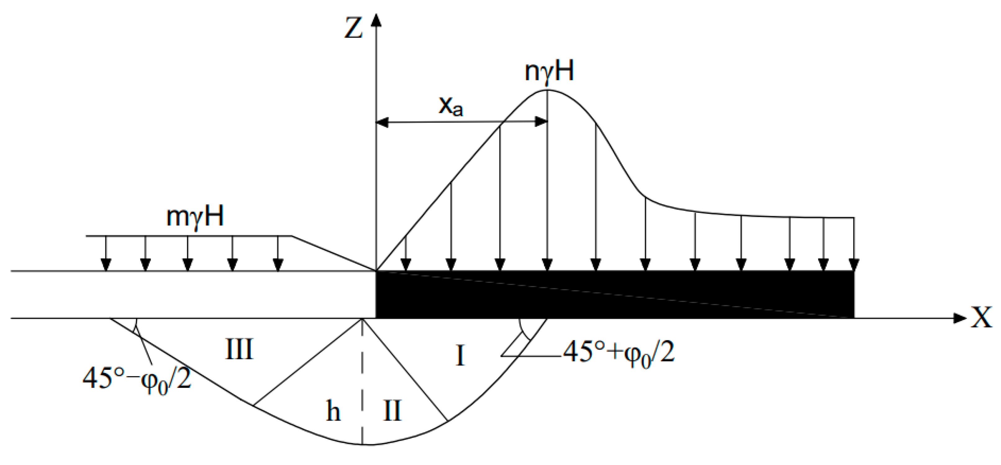
Figure 1. Schematic of the plastic failure of the bottom plate under the limit state.
Sustainability 15 09294 g001
Figure 2. Schematic of the reinforcement principle of cross-layer borehole grouting in the mine.
Sustainability 15 09294 g002
Figure 3. Schematic of the 1000 m directional borehole layout for ground area treatment.
Sustainability 15 09294 g003
Figure 4. Grouting reinforcement of floor mining-induced damage pipe pile-key stratum model.
Sustainability 15 09294 g004
Figure 5. Distributed bearing pressure and casing stress model.
Sustainability 15 09294 g005
Figure 6. Stress state at a point on the casing in space.
Sustainability 15 09294 g006
Figure 7. Schematic of the action mechanism of the cannula based on bending stiffness.
Sustainability 15 09294 g007
Figure 8. Schematic diagram of the damage of the confined water along the mining floor of the working face.
Sustainability 15 09294 g008aSustainability 15 09294 g008b
Figure 9. Mechanical model of the key waterproof layer.
Sustainability 15 09294 g009
Figure 10. Schematic of the coupling model of the “key layer” of regional governance.
Sustainability 15 09294 g010
Figure 11. Crack morphology and distribution.
Sustainability 15 09294 g011
Figure 12. Crack and block diagram.
Sustainability 15 09294 g012
Figure 13. Distribution of cracks and blocks in different schemes after regional treatment.
Sustainability 15 09294 g013
Figure 14. Distribution map of cracks and blocks before regional treatment.
Sustainability 15 09294 g014
Figure 15. Microseismic monitoring arrays of 230102 working face.
Sustainability 15 09294 g015
Figure 16. Microseismic monitoring array of 220106 working face.
Sustainability 15 09294 g016
Table 1. Meta-fine view parameters.
Density (kg/m3)Particle Diameters(mm)Ball–Ball Contact Modulus (GPa)Ball Stiffness RatioParallel-bond Modulus (GPa)Parallel-Bond Stiffness RatioBall Friction CoefficientParallel-Bond Shear Strength (MPa)Parallel-Bond Normal Strength (MPa)
20000.2–0.2520.820.80.10.70.5
Table 2. Medium numerical parameters.
Name of Rock StratumDensity/(Kg/m3)K/GPaG/GPaC/MPaφ/(°)Tensile Strength/MPa
Fine sandstone27002.825.301.28325.14
Coal seam194012.681.212.68231.50
Siltstone24959.137.224.42375.08
Mudstone27006.135.923.24372.08
Sandy mudstone25705.136.241.55274.08
Fine sandstone
Sandy mudstone
27808.133.223.41343.08
Siltstone24959.137.224.42375.08
Table 3. Statistical data of microseismic events in the working face.
HorizonFrequency of Microseismic Events (nos.)
230102 Working Face 220106 Working Face
1 coal bottom-1 ash top937917,387
C3 I limestone1967659
C3 II limestone770
C3 III limestone00
Ordovician limestone00
total11,42318,046
Disclaimer/Publisher’s Note: The statements, opinions and data contained in all publications are solely those of the individual author(s) and contributor(s) and not of MDPI and/or the editor(s). MDPI and/or the editor(s) disclaim responsibility for any injury to people or property resulting from any ideas, methods, instructions or products referred to in the content.