Article

Prediction and Application of the Height of Water-Conducting Fracture Zone in the Composite Roof: A Case Study of Jinxinda Coal Mine

Key Laboratory of Mining Engineering of Heilongjiang Province College, Heilongjiang University of Science and Technology, Harbin 150022, China
*
Author to whom correspondence should be addressed.
Sustainability 2023, 15(11), 9003; https://doi.org/10.3390/su15119003
Submission received: 30 March 2023 / Revised: 13 May 2023 / Accepted: 31 May 2023 / Published: 2 June 2023
(This article belongs to the Special Issue Advances in Coal Mine Disasters Prevention)

Abstract

:
The water inrush from the roof of the coal mine is closely related to the movement failure of overburdened rock and the height of the water-conducting fracture zone. In this work, based on the research background of water disaster prevention and control of the No. 2 coal seam roofs in Jinxinda Coal Mine, the stability characteristics of overlying rock in the working face are analyzed through combining theoretical analysis and numerical simulation. According to the theory of key strata, the fracture conditions of hard rock and soft rock are analyzed, and the maximum height of the water-conducting fracture zone in the 201 working face is calculated to be 35.72 m. The crack evolution law of composite roofs was simulated and analyzed using discrete element software. It was found that the basic roof (4.50 m thick) and the fine sandstone (7.64 m thick) are the two inferior key strata, and the maximum development height of the water-conducting crack is 36 m, which is basically consistent with the field measured results. Transient electromagnetic exploration technology was used to detect the working face, and nine abnormal areas were found. In order to prevent the influence of water disasters in abnormal areas during mining, drilling verification is carried out in abnormal areas. According to the analysis of drilling verification, there are no water disasters in the geophysical anomaly area, but the management of the roof after mining should be strengthened during mining. The expected research results not only enrich the rock formation control theory and roof water inrush mechanism; they also have important practical significance in guiding the safety production of a coal mine.

1. Introduction

With the gradual increase in the scale of mining resources, the scale of the mined-out area formed by mining and the overlying rock fracture zone increases, the water-collecting capacity and water-conducting capacity of the overlying mined-out area and the damaged rock layer increase, and the risk degree of mine water disasters increases [1,2,3]. In the theoretical research and production practice [4,5,6] conducted on the roof water inrush accident, based on surveying the spatial location, water richness, and water volume of the roof aquifer, goaf, and surface water by drilling and geophysical exploration, the emphasis is on determining the development height of the water-conducting fracture zone.
In terms of overburden deformation and fracture research, Xu et al. [7] examined the temporal effect of key strata on overburden activities, and the results showed that overburden failure and surface subsidence occurred simultaneously with key strata failure. Wang et al. [8] divided the evolution of the fracture zone height into two stages by studying the subsidence characteristics of surface points: in the first stage, the development of the fracture zone gradually transferred upward; in the second stage, the fracture zone height decreased, and the rock strata were compacted. Han et al. [9] set up a spatial–temporal subsidence model of overburden movement by using a continuum analysis method to study the influence of longwall mining speed on mining pressure and overburden movement. Guo et al. [10] analyzed and studied the stability of mining-induced overburden structures under a load of new buildings, and they established a mechanical model adapted to the engineering background to analyze the rationality of the stability criterion of the overburden strata. Guo et al. [11] used the elastic sheet theory to analyze the analytical solution of the three-dimensional fracture mechanics model of the basic roof for mining without a coal pillar. The fracture characteristics of the main roof cut by continuous and discontinuous artificial cracks are analyzed. Zuo et al. [12] analyzed and counted the types of strata fracture structures at different working faces, analyzed in detail the relationship between them and strata thickness, and established fracture mechanics models of strata with different thicknesses. Yuan et al. [13] studied the fracture characteristics of key strata with different mining thicknesses and the abutment’s stress response characteristics before and after the fracture of different key strata under a multi-key strata structure via numerical simulation given the overburden movement and surrounding rock stress of a complex thick coal working face under a multi-key strata structure.
The development of the water-conducting fracture zone is related to the overburden movement, so scholars have carried out a lot of research and obtained corresponding results. Liu et al. [14] measured the resistivity change of the whole stress–strain process of the rock sample under the condition of water filling, provided the change rule of the conductivity when the water-conducting fissure occurs in the floor of the coal seam during mining, and established the dynamic evolution model of the water-conducting fissure zone on this basis. Wang et al. [15] analyzed the movement and fracture development of overlying strata using a variety of methods such as theoretical calculation, similarity simulation, numerical simulation, and field measurement, and the research results provided a reasonable basis for determining a reasonable mining height. Zhu et al. [16] analyzed the fracture evolution law of overlying strata and the distribution characteristics of water channels under the influence of mining by studying the overlying strata activities on the working surface, thus obtaining the relationship between the law of ore pressure manifestation in the working face and the bridging of a water channel of overlying strata and providing basic theoretical guidance for research into water conservation and the anti-collapse procedures of the shallow coal seam. Zhou et al. [17] simulated the mining process of the working face through similar material tests, analyzed the evolution law of overlying rock fractures in the mining process, and summarized the distribution characteristics of the water channel. Based on the fractal dimension theory, the quantitative roof permeable danger zone is divided. Hou et al. [18] quantitatively described the development height and characteristics of the water-conducting fracture zone by analyzing the seismic characteristics of the water-conducting fracture zone, formed the fracture indicator data body by using neural network inversion and proposed a seismic identification method suitable for the development characteristics of the water-conducting fracture zone in the mining face. Zhou [19] and Gao et al. [20] used the micro-seismic monitoring system to study the caving characteristics of a thick, hard overburden in a fully mechanized caving face, as well as the fracture information of the internal structure of the overburden and the development height of the caving zone and fracture zone of the overburden after coal seam mining.
Based on the above research, this work takes the water disaster prevention of the No. 2 coal seam roof of Jinxinda Coal Mine as the research background, and the development law of composite roof fracture and the maximum height of the water-conducting fracture zone are analyzed via a combination of theoretical analysis and numerical simulation. Transient electromagnetic exploration technology was used to explore the working face, and to prevent the influence of water disasters in the abnormal areas during mining, drilling verification was carried out in the abnormal areas. The expected research results can not only enrich the rock formation control theory and roof water inrush mechanism; they also have important practical significance in guiding the safety production of a coal mine.

2. Overview of the Working Face

The 201 working face of Jinxinda Coal Mine is located in the north of the mining field, and the relative topography of the ground is mountains and gullies. The ground at 1886 m of the working face is Langwa Village. As shown in Figure 1, the strike length and inclination length of the 201 working face are 2403 m and 260 m, respectively, and the ground elevation is +1279~+1402 m. The east of the 201 working face is the boundary of the minefield, the west is the stopping line, the south is the former Xingou Coal mine 2108 air inlet roadway, and the north is the 202 working face (not mined). The total thickness of the coal seam is 0.9~1.2 m, and the average thickness is 1.05 m. The inclination angle of the coal seam is 0~3°, and the fluctuation of the coal seam is relatively slow; it is a semi-bright coal sandwich bright coal, soft, stable coal seam.
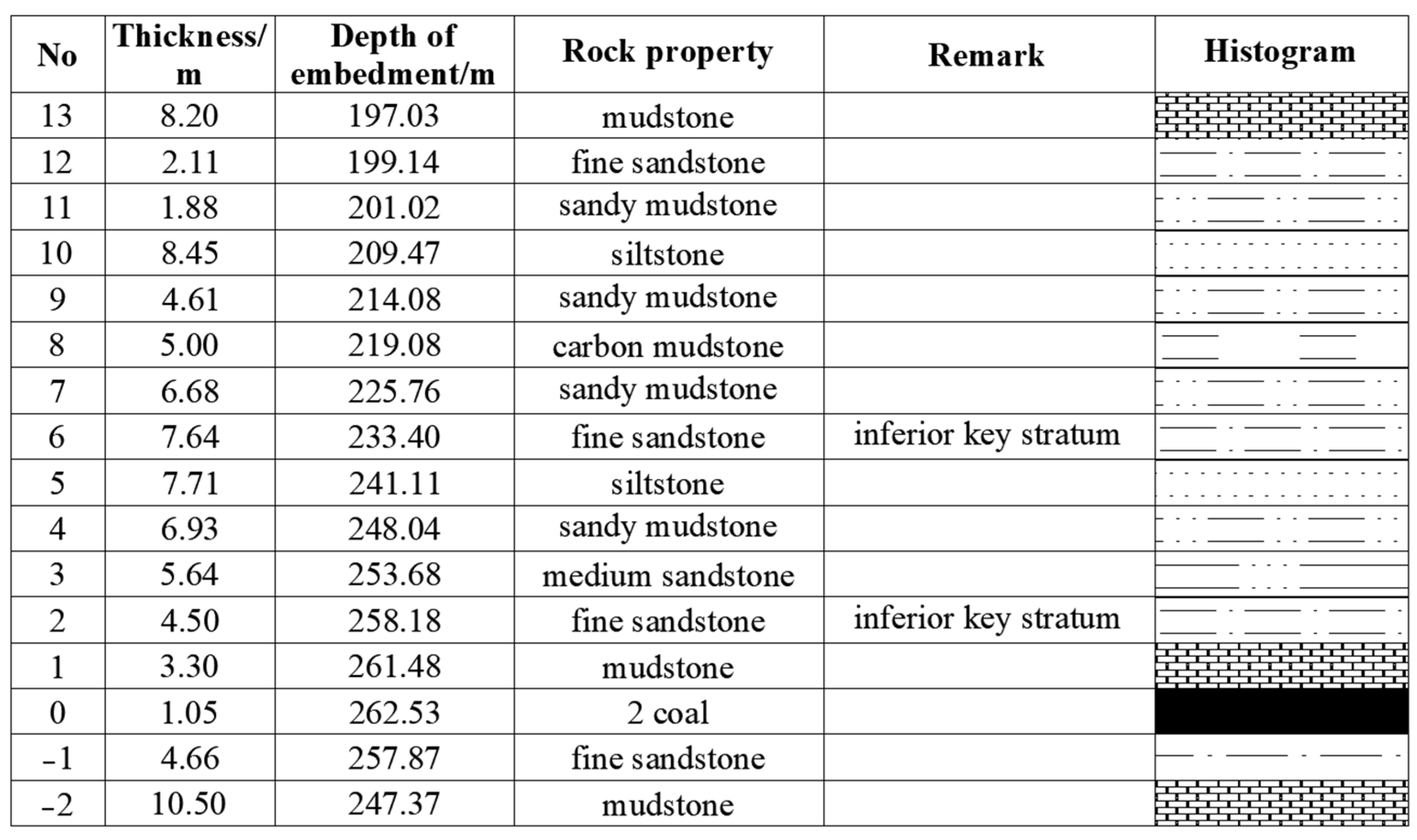
The main roof thickness is 4.5 m, and the lithology of fine sandstone is a hard, thick layer, not easily caving, with layer stability. The thickness change is not large as the coal seam roof is, on the whole, relatively flat, but there is a partial uneven phenomenon: the bedding is not obvious, and there crack development belong to half-hard-to-hard rock. The thickness of the direct roof is 3.3 m, which is mainly dark gray sandy mudstone and mudstone; it soft and easily caving, and poor stability. The pseudo-roof thickness is 0.45~1.65 m, with an average thickness of 0.8 m. It is mainly composed of sandy mudstone and coal line. It is soft and easily caving, and its stability is poor. The thickness of the direct floor is 4.66 m; it is composed of black-gray fine sandstone, thick layered and soft. The thickness of the old floor is 10.5 m; it is composed of a gray-black, thin layer of mudstone, mainly feldspar, quartz, sub-round, and medium-sorting basal-type cement. The details are shown in Figure 2.

3. Analysis of Overburden Rock Stability Characteristics of the Working Face

3.1. Key Strata Characteristics and Discrimination Method

If n strata are deformed synchronously and harmoniously, the lowest stratum is the key stratum [21,22,23]. Based on the supporting characteristics of the key strata, it can be seen that:
q 1 > q i ( i = 2 , 3 , , n ) .
Similarly, the load on the n + 1 stratum must be greater than that on the lower stratum [23,24,25], namely:
q 1 | n + 1 > q 1 | n ,
where
q 1 | n + 1 = E 1 h 1 3 ( i = 1 n γ i h i + q n + 1 ) i = 1 n + 1 E i h i 3 ,
where E is elastic modulus, h is rock thickness, γ is bulk density, and q is load.
If n + 1 < m, then qn+1 shall be solved by Equation (3) until its solution can be controlled to stratum m.
If n + 1 = m, then qn+1 = γmhm + q;
If n + 1 > m, then qn+1 is [23,24,25]:
q n + 1 | m n = E n + 1 h n + 1 3 ( i = n + 1 m γ i h i + q ) i = n + 1 m E i h i 3 .
The expression form of Equation (2) is the load, which can also be expressed by deflection. If the n + 1 stratum is the key stratum, its breaking distance is ln+1, and the braking distance of the first stratum is l1, then the strength discrimination condition of the key stratum is [23,24] as follows:
l n + 1 > l 1 .
When stratum 1 is the inferior key stratum, the thickness and number of strata controlled by key stratum 1 can be determined by using Formulas (2) and (5). If n = m, key stratum 1 is the primary key stratum. If n < m, key stratum 1 is inferior key stratum.
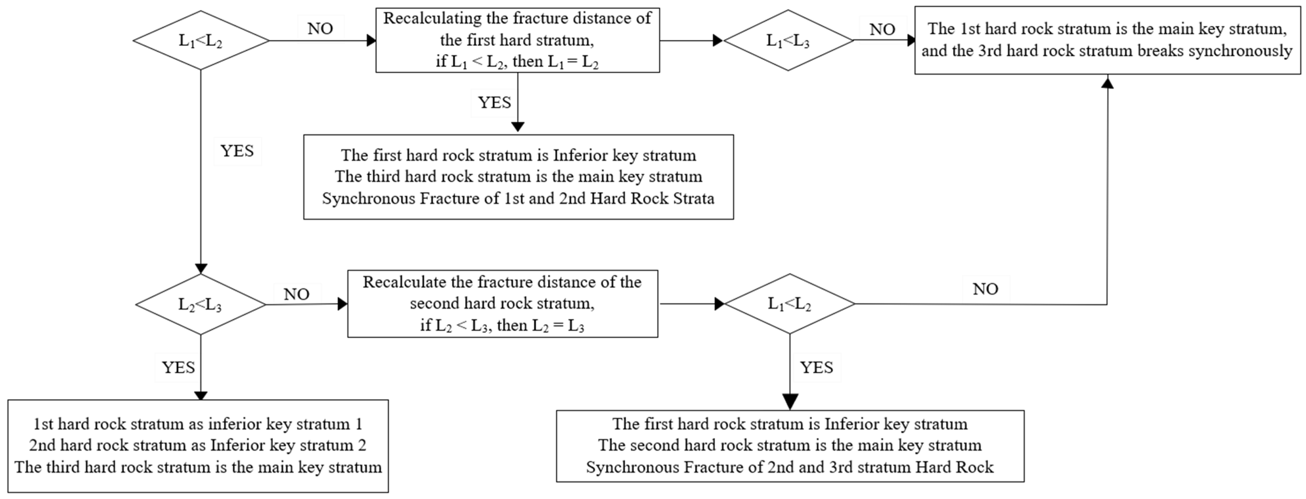
The specific process of key stratum discrimination is shown in Figure 3. According to this discriminant method, the distribution of key strata of the overlying strata on the 201 working face can be obtained: the basic roof of fine sandstone of 4.5 m is the inferior key stratum; and the overlying fine sandstone of 7.64 m is also the inferior key stratum.

3.2. Stability Analysis of Overburden of the Working Face

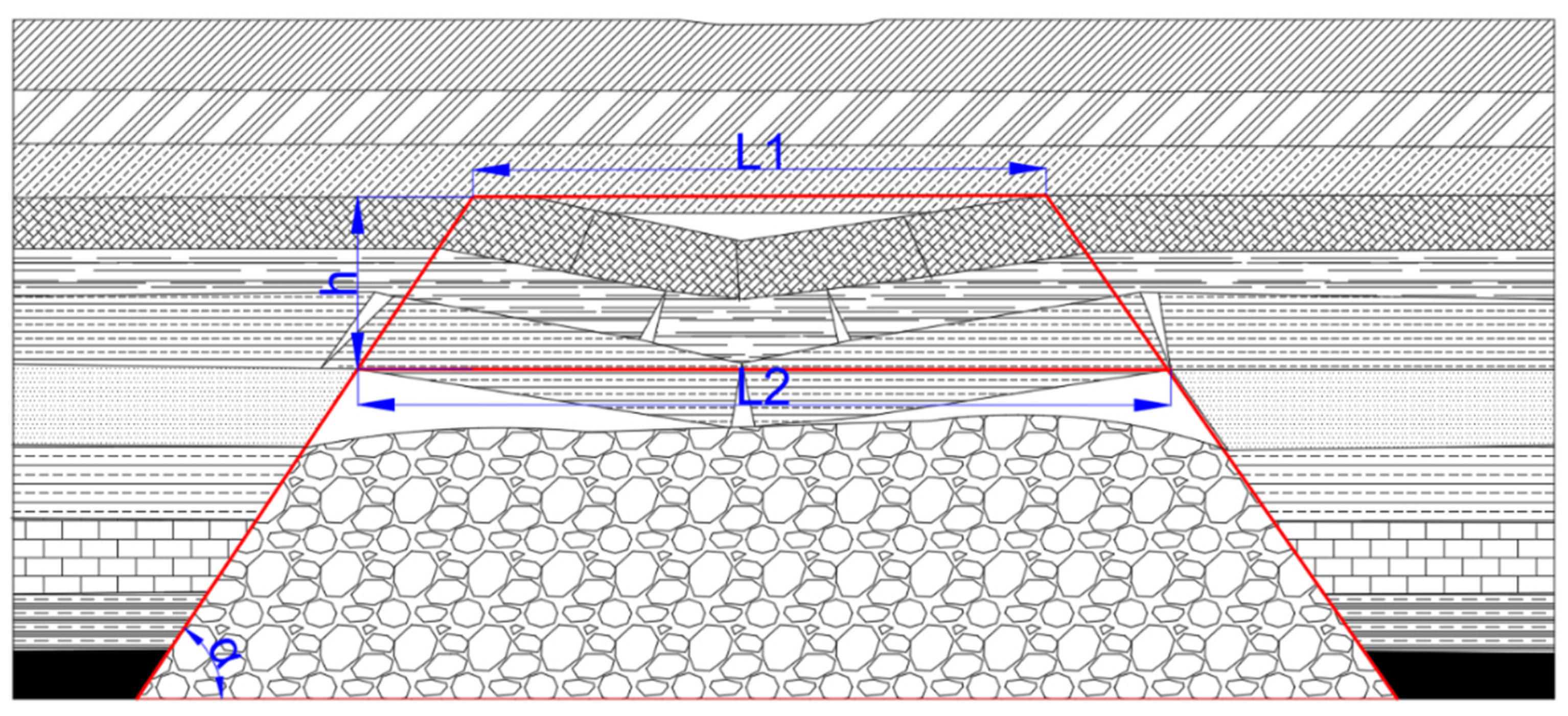
As shown in Figure 4, the critical overhang distance of the lower key stratum is assumed to be L1; the overhang distance of the adjacent key stratum above it is L2 after the key stratum below it is fractured; the interlayer thickness between the two key strata is h; and the angle between the rock fracture line and the horizontal line of the stope space is αl thus, it meets the following requirements:
L 1 = L 2 + 2 h cot α .
Similarly, Equation (6) can also be used to express the geometric relationship between stope space and key strata. When L1 reaches the critical distance of the underlying key stratum and breaks, if the overlying hard rock is the key stratum, L2 is not required to reach its ultimate strength, namely:
L upper > L 1 = L 2 + 2 h cot α ,
where α is the fracture angle of rock strata.
In combination with Equations (6) and (7), the relationship between the critical fracture value of the key stratum and the working face is established. Assuming that a is the overhang length of the long side of the key stratum, then:
a = 4 h λ ( 1 + 4 7 λ 2 + λ 4 ) R t 42 q + 2 h cot α ,
where q is the bearing capacity of the key stratum, whose bearing capacity comes from the weight of the following stratum and the key stratum itself; h is the thickness of the key stratum; λ is the ratio of the short side and the long side of the overhang length of the key stratum—that is, b = λa, b is the overhang length of the short side of the key stratum; Rt is the tensile strength of the key stratum; and Σh is the strata thickness between the key stratum and the working face.
Whether the key stratum can keep balance after fracture depends on whether the “three-hinged arch” structure can keep balance—that is, whether there is sliding instability or deformation instability. This is to judge whether the relationship between the thickness of the key stratum, the length of the fracture block, and the friction angle of the block meets the following requirements:
h L / 2 1 2 tan φ ,
where φ is the friction Angle between rocks.
If Equation (7) is satisfied, it is necessary to further determine whether the deformation and instability will occur after the key strata fracture—that is, whether the rock mass occlusion point is damaged after the key strata fracture, and the equilibrium extrusion force σp is required to be satisfied:
σ p = 2 q L 2 ( h L sin β ) 2 < σ c ,
where β is the angle of rock block fracture and σc is the compressive strength of rock.
If the geometric dimensions and extrusion force of the key strata meet Equations (9) and (10) after fracture, it is considered that the key strata only fracture without collapse; as long as one of the conditions is not met, it is considered to fail. According to the above analysis, the initial breaking step distance and the periodic breaking step distance of the basic roof (inferior key stratum) are 25.4 m and 14.6 m, respectively, which are basically consistent with the coming pressure step distances obtained from on-site pressure monitoring.

4. Theoretical Analysis of the Development Height of Water-Conducting Fracture Zone

4.1. Hard Rock Fracture Analysis

Structurally, the rock mass is a complex composed of rock blocks and structural planes. According to the overall characteristics of its failure, it can be divided into brittle and plastic failures. The stress strength factor can be used as the index to measure whether hard rock strata break and conduct water. According to the fixedly supported beam model, the maximum tensile stress is as follows:
σ max = 12 M max y max / h 3 = q l 2 2 h 2 ,
where l is the beam length and h is the beam thickness.
The rock beam breaks when σmax = σt (σt is the ultimate tensile strength), and the ultimate span is as follows:
l G = h 2 σ t q .
Therefore, the critical mining length of hard rock fracture is as follows:
l g , j = i = 1 m h i cot ϕ q + l G , j + i = 1 m h i cot ϕ h ,
where lg,j is the advancing length of the working face when the j-th stratum (hard rock) is broken; hi is the thickness of stratum i; m is the number of strata from the roof to the j − 1 stratum of the coal seam; and ϕ h denotes the fracture angles in the front and back of the strata, respectively.

4.2. Soft Rock Strata Fracture Analysis

The strain strength factor is used as the index to judge whether the soft rock is broken. Combined with the mechanical model of the fixedly supported beam, the bending equation of the soft rock stratum is as follows:
w = a 1 ( 1 + cos 2 π x l ) + a 2 ( 1 + cos 6 π x l ) + ... + a n ( 1 + cos n ( 2 n 1 ) π x l )
After substituting the balance equation into the flexion equation and the Galerkin integral equation, we can obtain the following:
0 l [ E I d 4 w   d x 4 q ] w n ( x ) d x = 0 .
By expanding the above equation, we obtain
a n = q l 4 8 ( ( 2 n 1 ) π ) 4 E I .
The form expressed in span is as follows:
l R = h 8 E ε max 3 q   .
Considering the influence of rock fracture angle, the span can be further expressed as follows:
l r , j = i 1 m h i cot ϕ q l R , j + i = 1 m h i cot ϕ h ,
where l r , j is the advancing length of the working face when the j stratum (soft rock) is broken.

4.3. Prediction of the Development Height of Water-Conducting Fracture Zone

The free space formed after coal seam mining will be filled by the characteristics of overburden fracturing and swelling. If we consider that only the rock strata in the caving zone and fracture zone produce crushing expansion, while the rock strata in the bending and sinking zone do not change in volume, the free space height under each stratum can be obtained as follows:
Δ i = M j = 1 i 1 h j ( k j 1 ) ,  
where ∆i is the height of the i-th stratum free space; M is mining height; hj is the thickness of the j-th stratum; and kj is the fracture swelling coefficient of the j-th stratum.
The key to the failure of the weak strata is whether its maximum strain reaches the plastic deformation limit, and the strain can be analyzed by deflection. Therefore, the judgment relationship is transformed into the relationship between whether or not the free space under the weak rock stratum is the maximum deflection of the rock stratum. If the condition of less than is met, the rock stratum will break and conduct water. Note the following:
w i , max > M j = 1 i 1 h j ( k j 1 ) ,
where w i , max is the maximum deflection of soft rock strata.
The formation of separation lies in the discordant deformation of upper and lower strata, and this discordance will not lead to a qualitative change in the overburden bearing structure. Therefore, in the calculation, it can be considered that when the difference of deflection between two adjacent strata reaches a certain level, the separation of strata occurs:
w i , max > w i + 1 , max + c ,
where c is the set deflection difference of adjacent rock strata.
According to the above method of predicting the height of water-conducting fracture development, combined with the overburden structure given in Figure 4, the development height of the water-conducting fracture zone in the 201 fully mechanized working face of Jinxinda Coal Mine is theoretically analyzed, and the calculation results are shown in Table 1. The maximum mining height is 2.8 m. According to the theoretical calculation, the maximum height of the water-conducting fracture zone is 35.72 m, which is basically consistent with the field measurement results.

5. Numerical Simulation of Fracture Evolution in Composite Roof

5.1. Establishment of Numerical Model

UDEC discrete element simulation software is used to set up a two-dimensional numerical model. The dip angle of the No. 2 coal seam is 0~3°, which is simplified to 0°. The average thickness of the coal seam is 1.05 m, but the maximum mining height of the working face is 2.8 m due to the occurrence of gangue in the coal seam; thus, the simulated mining height is 2.8 m. The average buried depth of the No. 2 coal seam is 260 m, and the mining depth in the numerical model is 187 m, so the equivalent load of 73 m rock strata is applied on the upper part. According to the geological data, we set up a calculation model with a length of 700 m and a height of 320 m. The mining boundary on the left and right sides of the model is 200 m away from the boundaries of the model, as shown in Figure 5. The Mohr–Coulomb model was used for the model block, and the Coulomb contact slip model was used for the joint model. The left and right sides and the bottom of the model are subject to displacement constraints.
Mechanical parameters of rock mass and joints are shown in Table 2 and Table 3. To simulate the collapse of roof strata after mining, the cohesion and tensile strength of inter-strata joints are much smaller those that of intra-stratum joints.

5.2. Analysis of Simulation Results of Fracture Evolution in Composite Roof

Comprehensively considering the progress of the actual working face on site and the computing rate of the computer, the simulated advance speed of the working face is 10 m per step—a total of 30 steps and a total of 300 m.
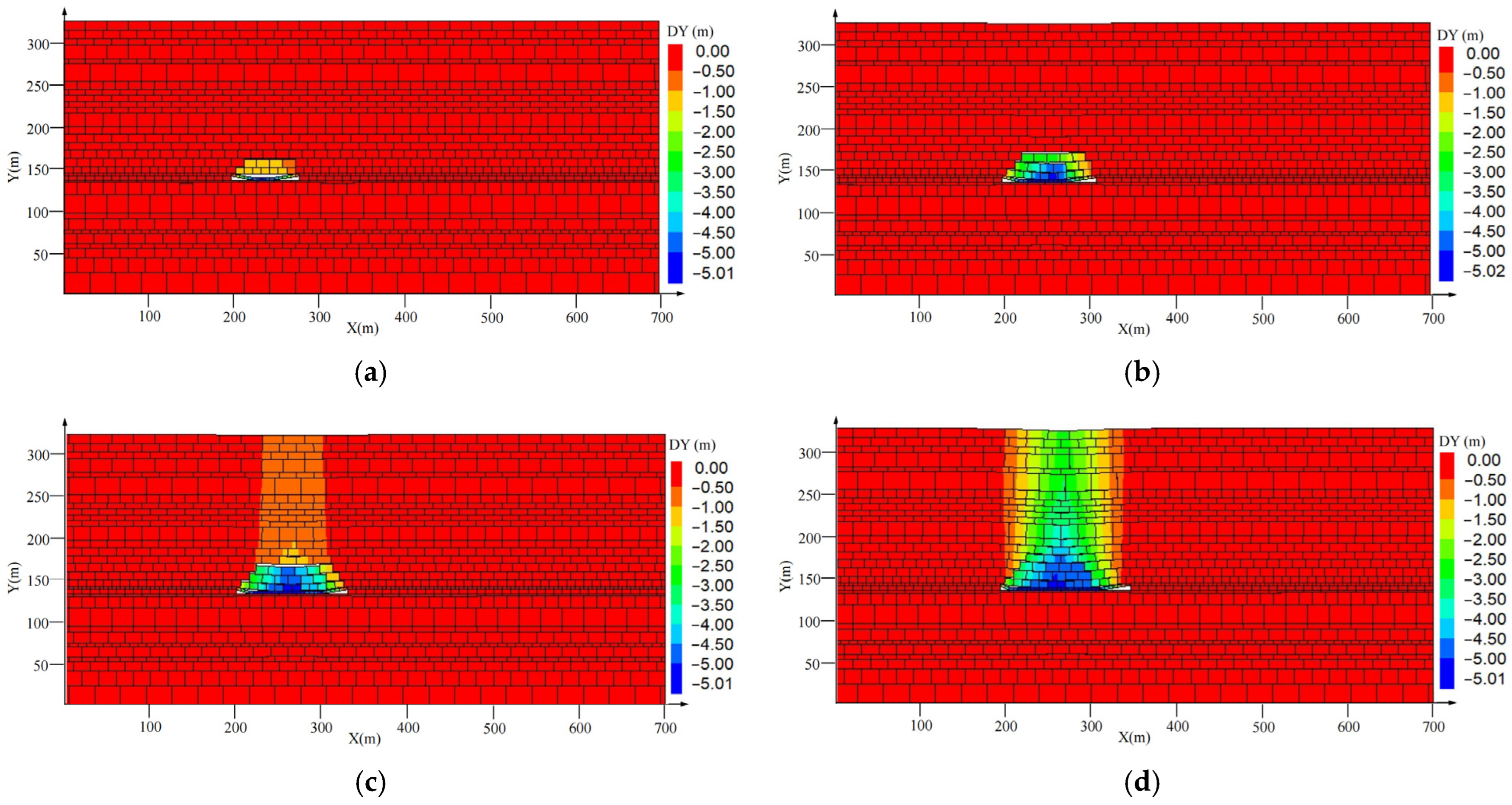
Figure 6 shows the evolution process of vertical displacement of the overburden in the working face. With the advance of the No. 2 coal seam working face, obvious displacement changes occur in the coal seam roof, and the displacement variation area expands continuously. When the working face is advanced to 80 m, the direct roof of the coal seam has been deformed and collapsed. Then, for every step (10 m) the working face advanced, the first stratum (direct roof) breaks. When the working face advances to 120 m, the third and fourth strata of rock mass above the coal seam begin to separate; when the working face is advanced to 140 m, the amount of strata separation reaches the maximum. Later, with the advancing of the working face, the strata separation is gradually compacted, and the surface displacement increases. When the working face advances to 170 m, the separation stratum begins to occur between the fifth stratum and the sixth stratum above the coal seam. The separation amount of this stratum reaches the maximum when the working face advances to 180 m, and then the separation stratum is gradually compacted with the advance of the working face. When the working face advanced to 190 m, the separation stratum began to form between the sixth stratum and the seventh stratum above the coal seam. The separation amount of this stratum reached the maximum when the working face advanced to 210 m, and the separation stratum was gradually compacted with the advance of the working face. With the mining of the working face, there is no obvious separation phenomenon above the seventh stratum. When the working face advances to 300 m, it can be seen that the eight stratum rock mass above the working face has a strong control effect on the change of vertical displacement.
Figure 7 shows a typical distribution image of fracture evolution in the advancing process of the working face. As can be seen from the figure, when the working face is advanced to 100 m, the overburden fracture is fully developed, and the development height reaches 7.64 m, which is inferior to key stratum 2 (fine sandstone). The rock stratum has been broken, and the fractures below are relatively dense. The fractures above are mainly interlayer separation fractures, and the vertical fractures are not fully developed; that is, the mining fractures above the inferior key stratum 2 fail to form the intersecting water-conducting fractures. With the working face advance, the inferior key stratum 2 above the working face side and in front of the local mining fractures gradually closed, and, ceaselessly, new fractures, adhering to mining-induced fracture laws similar to when the working face advanced to 100 m—are produced. The inferior key stratum 2 at the bottom of the overburden rock fracture has been developed fully, but the water-conducting fractured zone height has been basically stable, i.e., it no longer extends upwards; the height of the water-conducting fracture zone finally stabilizes at 36 m. It can be seen from the above that new fractures appear in the strata controlled by the inferior key stratum 1 along with the fracture of inferior key stratum 1. Both vertical and transverse fractures are fully developed, and water-conducting fractures can be formed. When the strata controlled by the inferior key stratum 2 advanced with the working face, the vertical fractures were not sufficiently developed due to the existence of soft rocks such as mudstone; that is, the development of water-conducting fractures was inhibited.

6. The 201 Working Face Water Disaster Assessment and Prevention Plan

6.1. Analysis of Geophysical Anomaly Area of Working Face

To further find out the internal bedding direction of the water of the 201 working face, and to reduce water unexpected disasters, transient electromagnetic exploration technology is used to analyze the working face. The basic working method is to set up a transmitting coil with a certain waveform current in the well to generate a primary magnetic field in the surrounding space and generate an induced current in the underground conductive rock orebody. After a power failure, the induced current decays with time due to heat loss. The geoelectric characteristics of different depths can be obtained by measuring the change of the secondary field with time in each period after power failure. Because the water resistance is lower than coal, the abnormal area of low resistance is key to preventing water disasters.
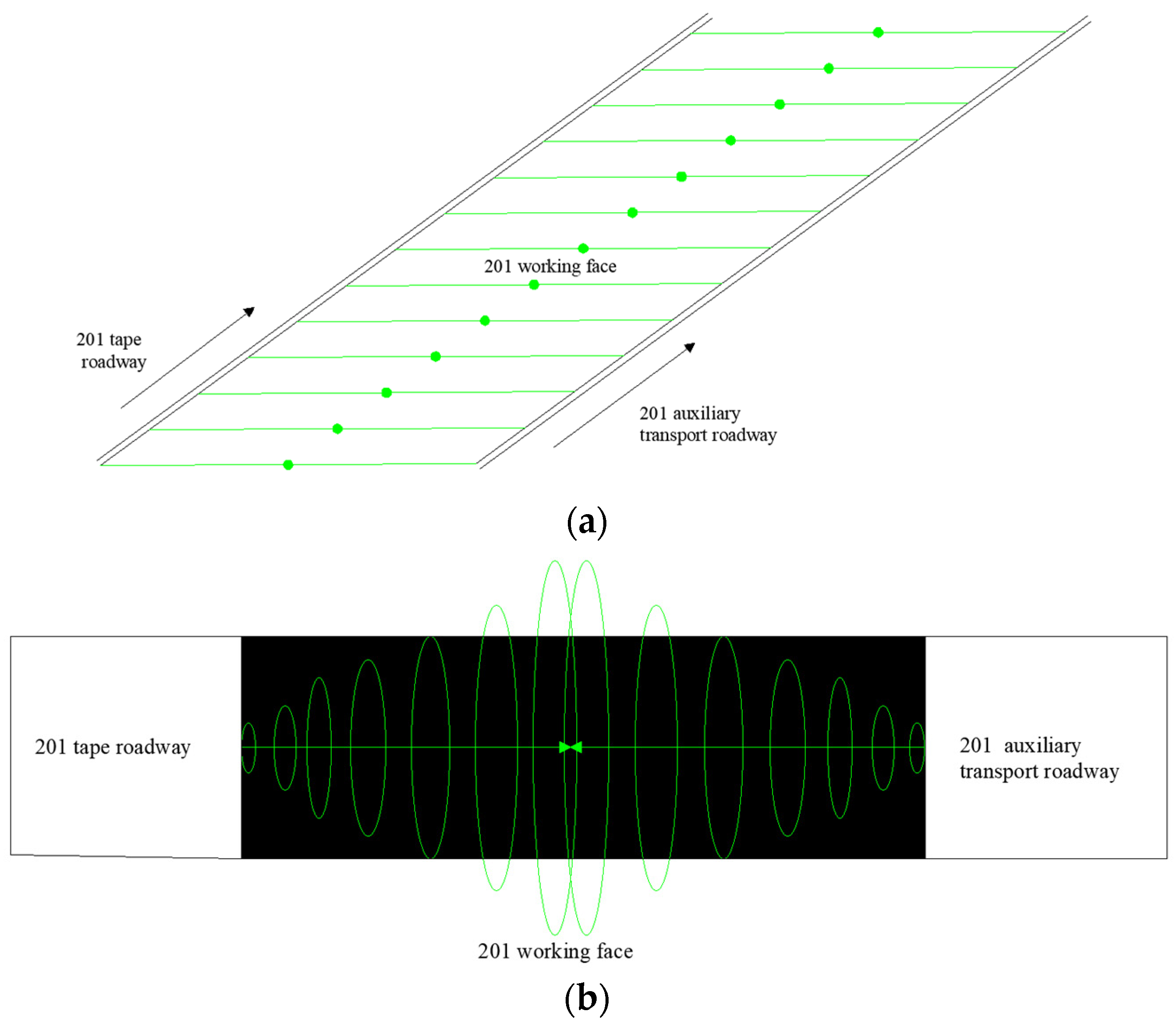
The transient electromagnetic construction of the 201 working face is shown in Figure 8. The measuring points were spaced 10 m apart, and two measured profiles were formed by moving the transmitting and receiving coils. A survey line is arranged along the trough of the 201 auxiliary transport roadway (in the direction of the working face bedding), and the survey line is 2350 m long. The point 9.8 m before the FS3 point of the roadway is the start position, and the open-off cut is the end position. One survey line is arranged along the 201 tape roadway (in the direction of the bedding of the working face), and the length of the survey line is 2350 m. The starting position is 10.8 m before the JS2 point of the roadway, and the end position is the open-off cut.
According to the detection results of the auxiliary transport roadway and the tape roadway on the 201 working face, a total of nine abnormal areas were detected. Among them, size anomalies were detected in the 201 auxiliary transport roadway, and additional anomalies were detected in the 201 tape roadway, as shown in Table 4.

6.2. The 201 Working Face Water Disaster Assessment and Exploration and Drainage Plan for Geophysical Anomaly Area

During mining, roof caving will destroy the integrity of the rock above the roof, resulting in water from the aquifer flowing into the working face along the fractures. The maximum mining height of the 201 working face is 2.8 m, and the maximum heights of the water-conducting fracture zone obtained by field measurement, theoretical analysis, and numerical simulation are 39.18 m, 35.72 m, and 36 m, respectively. The roof water has a certain influence on the mining of the 201 working face.
To prevent the effect of geophysical exploration and water disasters in the abnormal area of the in-seam wave during mining, the abnormal area was verified by drilling. A ZDY-1900 L crawler hydraulic tunnel drill is used for drilling, and the drill is adjusted 1.6 m away from the floor according to the designed angle. A total of nine drilling fields and 18 drilling holes are arranged in the tape and auxiliary transport roadway on the 201 working face.
The water exploration and drainage project verified a total of 13 geophysical exploration and in-seam wave anomaly areas, including 9 transient electromagnetic anomaly areas and 4 in-seam wave anomaly areas. There were no abnormal water disasters in 18 verification holes. Anomaly zones 4 and 6 location are located on the 2108 roadway. In the actual production process, the drainage volume is 1100 m3 through the special drain measures. The roadway is unsealed at present. Through the field observation of geophysical anomaly zones 4 and 6, from the corresponding position of the low-lying point drift a small amount of water has been emitted, so the geophysical anomaly zones 4 and 6 do not need drilling verification.
Through the analysis of the drilling verification of the transient electromagnetic anomaly area and the in-seam wave anomaly area of the working face, it is found that there are no abnormal water disasters in the geophysical anomaly area. However, the observation of the change in the roof after mining suggests that the roof should be strengthened during mining, and the water flow of the working face should be seen. If there is any problem or flood, the mining should be organized after the flood is confirmed and eliminated.

7. Discussion

Based on the theory of the key layer, the height of the water-conducting fracture zone is analyzed. Combining numerical simulation and field monitoring, the correctness of the theoretical analysis is verified, but there are some shortcomings:
(1)
Numerical simulation: The development law of vertical displacement and fracture during mining is analyzed. Due to the space limitation, the fracture development law is not analyzed from the perspective of stress, and this part is not sufficiently detailed. In the follow-up study, the mining process will be comprehensively analyzed.
(2)
On-site monitoring: Due to space constraints, the monitoring data and analysis process of the transient electromagnetic method are not discussed, and neither are the drilling plan and other contents. In later research, this part of content will be focused on.

8. Conclusions

Based on the research background of Jinxinda Coal Mine, this work analyzed the stability characteristics of the overlying rock, as well as the fracture conditions of hard rock and soft rock, and calculated the height of the water-conducting fracture zone by using the theory of elasticity, key strata theory, and thin plate theory. With the help of discrete element software, the mining deformation, failure characteristics, and evolution law of composite roofs were simulated and analyzed, and the evaluation and prevention plan of a working face water disaster was carried out. The main conclusions were drawn as follows:
(1)
Based on the theory of elasticity, key strata theory, and thin plate theory, the initial breaking step distance, periodic breaking step distance, and the maximum height of the water-conducting fracture zone of the 201 working face are, respectively, 25.4 m, 14.6 m, and 35.72 m, which are basically consistent with the field measured results.
(2)
The migration and fracture evolution laws of mining-induced overburden are analyzed using discrete element software simulation. The simulation results show that the development of water-conducting fractures in the overlying strata is closely related to the movement of the fracture structure of the key strata. The basic roof with a thickness of 4.50 m and the fine sandstone with a thickness of 7.64 m are the two inferior key strata close to the 201 working face, and the height of the water-conducting fracture zone is finally stable at 36 m.
(3)
According to the detection results of the transient electromagnetic method in the 201 mining working face, nine abnormal areas were explored, and the abnormal areas were verified by drilling. The results show that there is no water disaster in the geophysical anomaly area but indicate that miners should improve their observations of the roof change after mining in the working face; pay attention to see the working face water flow situation; and if there is a problem or flood situation, confirm and eliminate the flood before organizing mining.

Author Contributions

Conceptualization, G.Z.; validation, W.X.; formal analysis and investigation, T.Q. and Y.D.; data curation, G.Z., W.X. and T.Q.; writing—original draft preparation, W.X. and Y.D.; writing—review and editing, W.X. and X.H.; supervision, G.Z. All authors have read and agreed to the published version of the manuscript.

Funding

This work was supported by the Scientific and Technological Key Project of “Revealing the List and Taking Command” in Heilongjiang Province: Study on geological model and ventilation model of intelligent mining in extremely thin coal seam (2021ZXJ02A03); and Outstanding Young Talents Project supported by the Central Government for The Reform and Development of Local Universities (2020YQ13).

Institutional Review Board Statement

Not applicable.

Informed Consent Statement

Not applicable.

Data Availability Statement

Not applicable.

Conflicts of Interest

The authors declare no conflict of interest.

References

  1. Fan, L.M.; Ma, X.D.; Jiang, Z.Q.; Sun, K.; Ji, R.J. Review and thirty years prospect of research on water-preserved coal mining. Coal Sci. Technol. 2019, 47, 1–30. [Google Scholar] [CrossRef]
  2. Li, L.P.; Jia, C.; Sun, Z.Z.; Liu, H.L.; Cheng, S. Research status and development trend of major engineering disaster prevention and control technology in deep underground. J. Cent. South Univ. Sci. Technol. 2021, 52, 2539–2556. [Google Scholar]
  3. Zhang, P.S.; Xu, S.A.; Guo, L.Q.; Wu, R.X. Prospect and progress of deformation and failure monitoring technology of surrounding rock in stope. Coal Sci. Technol. 2020, 48, 14–48. [Google Scholar] [CrossRef]
  4. Lai, X.P.; Zhang, X.D.; Shan, P.F.; Cui, F.; Liu, B.W.; Bai, R. Study on development law of water-conducting fractures in overlying strata of three soft coal seam mining under thick loose layers. Chin. J. Rock Mech. Eng. 2021, 40, 1739–1750. [Google Scholar] [CrossRef]
  5. Yang, G.Y.; Chen, C.; Gao, S.L.; Feng, B. Study on the height of water flowing fractured zone based on analytic hierarchy process and fuzzy clustering analysis method. J. Min. Saf. Eng. 2015, 32, 206–212. [Google Scholar] [CrossRef]
  6. Shi, L.Q.; Xin, H.Q.; Zhai, P.H.; Li, S.C.; Liu, T.B.; Yan, Y.; Wei, W.X. Calculating the height of water flowing fracture zone in deep mining. J. China Univ. Min. Technol. 2012, 41, 37–41. [Google Scholar]
  7. Xu, J.L.; Qian, M.G. Study on the influence of key strata movement on subsidence. J. China Coal Soc. 2000, 25, 122–126. [Google Scholar] [CrossRef]
  8. Wang, H.B.; Zhang, Y.; Pang, Y.H.; Zhang, C.L. Evolution of the Height of overburden fracture zone based on stage characteristics of surface subsidence. J. China Univ. Min. Technol. 2022, 51, 24–34. [Google Scholar] [CrossRef]
  9. Han, P.H.; Zhang, C.; Ren, Z.P.; He, X.; Jia, S. The influence of advance speed on overburden movement characteristics in longwall coal mining: Insight from theoretical analysis and physical simulation. J. Geophys. Eng. 2021, 18, 163–176. [Google Scholar] [CrossRef]
  10. Guo, W.B.; Yang, W.Q.; Ma, Z.B.; Wen, P.; Liu, X.; Bai, E.H. Stability criterion of overburden structure above goaf under building load and its application. J. China Coal Soc. 2022, 47, 2207–2217. [Google Scholar] [CrossRef]
  11. Guo, S.; Tai, Y.; Wang, Z.W.; Shi, B.W.; Yang, K. Fracture characteristics of basic roof and mechanism of strata behavior in a pillarless working face. J. Geophys. Eng. 2021, 18, 875–889. [Google Scholar] [CrossRef]
  12. Zuo, J.P.; Yu, M.L.; Sun, Y.J.; Wu, G.S. Analysis of Fracture Mode Transformation Mechanism and Mechanical Model with Different Thickness Rock Strata. J. China Coal Soc. 2022, 1–18. [Google Scholar] [CrossRef]
  13. Yuan, F.; Ma, Z.K.; Tang, C.A.; Wang, S.J.; Guo, H.Y. Movement of overburden with different mining thickness and response characteristics of surrounding rock under multi-key layer structure. Coal Sci. Technol. 2022, 50, 211–218. [Google Scholar] [CrossRef]
  14. Liu, S.C.; Liu, X.M.; Jiang, Z.H.; Xing, T.; Chen, M.Z. Research on Electrical Prediction for Evaluating Water Conducting Fracture Zones in Coal Seam Floor. J. Rock Mech. Eng. 2009, 28, 348–356. [Google Scholar]
  15. Wang, F.; Tu, S.; Zhang, C.; Zhang, Y.W.; Bai, Q.S. Evolution mechanism of water-flowing zones and control technology for longwall mining in shallow coal seams beneath gully topography. Environ. Earth Sci. 2016, 75, 1309. [Google Scholar] [CrossRef]
  16. Zhu, W.B.; Wang, X.Z.; Kong, X.; Liu, W.T. Study of mechanism of stope water inrush caused by water accumulation in overburden separation areas. Chin. J. Rock Mech. Eng. 2009, 28, 306–311. [Google Scholar]
  17. Zhou, H.W.; Zhang, T.; Xue, D.J.; Xue, J.H. Evolution of mining-induced crack network in overburden strata of longwall face. J. China Coal Soc. 2011, 36, 1957–1962. [Google Scholar] [CrossRef]
  18. Hou, E.K.; Yuan, F.; Wang, S.M.; Xie, X.S.; Wu, B.H. Seismic identification and development characteristics of water conducting fissure zone in goaf. J. China Coal Soc. 2023, 48, 414–429. [Google Scholar] [CrossRef]
  19. Zhou, Y.; Yu, X.Y. Study of the Evolution of Water-Conducting Fracture Zones in Overlying Rock of a Fully Mechanized Caving Face in Gently Inclined Extra-Thick Coal Seams. Appl. Sci. 2022, 12, 9057. [Google Scholar] [CrossRef]
  20. Gao, W.; Li, Y.C.; He, Q.Y. Determination of Fractured Water-Conducting Zone Height Based on Microseismic Monitoring: A Case Study in Weiqiang Coalmine, Shaanxi, China. Sustainability 2022, 14, 8385. [Google Scholar] [CrossRef]
  21. Qian, M.G.; Miao, X.X.; Xu, J.L. Theoretical Study of key stratum in ground control. J. China Coal Soc. 1996, 3, 2–7. [Google Scholar]
  22. Qian, M.G.; Xu, J.L. Behaviors of strata movement in coal mining. J. China Coal Soc. 2019, 44, 973–984. [Google Scholar] [CrossRef]
  23. Miao, X.X.; Chen, R.H.; Pu, H.; Qian, M.G. Analysis of breakage and collapse of thick key strata around coal face. Chin. J. Rock Mech. Eng. 2005, 8, 1289–1295. [Google Scholar]
  24. Qian, M.G.; Miao, X.X.; Xu, J.L. Key Strata Theory in Ground Control; China University of Mining and Technology Press: Xuzhou, China, 2003. [Google Scholar]
  25. Li, Y.; Yang, T.H.; Song, W.D.; Yu, L. Movement Law and Discriminant Method of Key Strata Breakage Based on Microseismic Monitoring. Shock. Vib. 2019, 2019, 865289. [Google Scholar] [CrossRef] [Green Version]
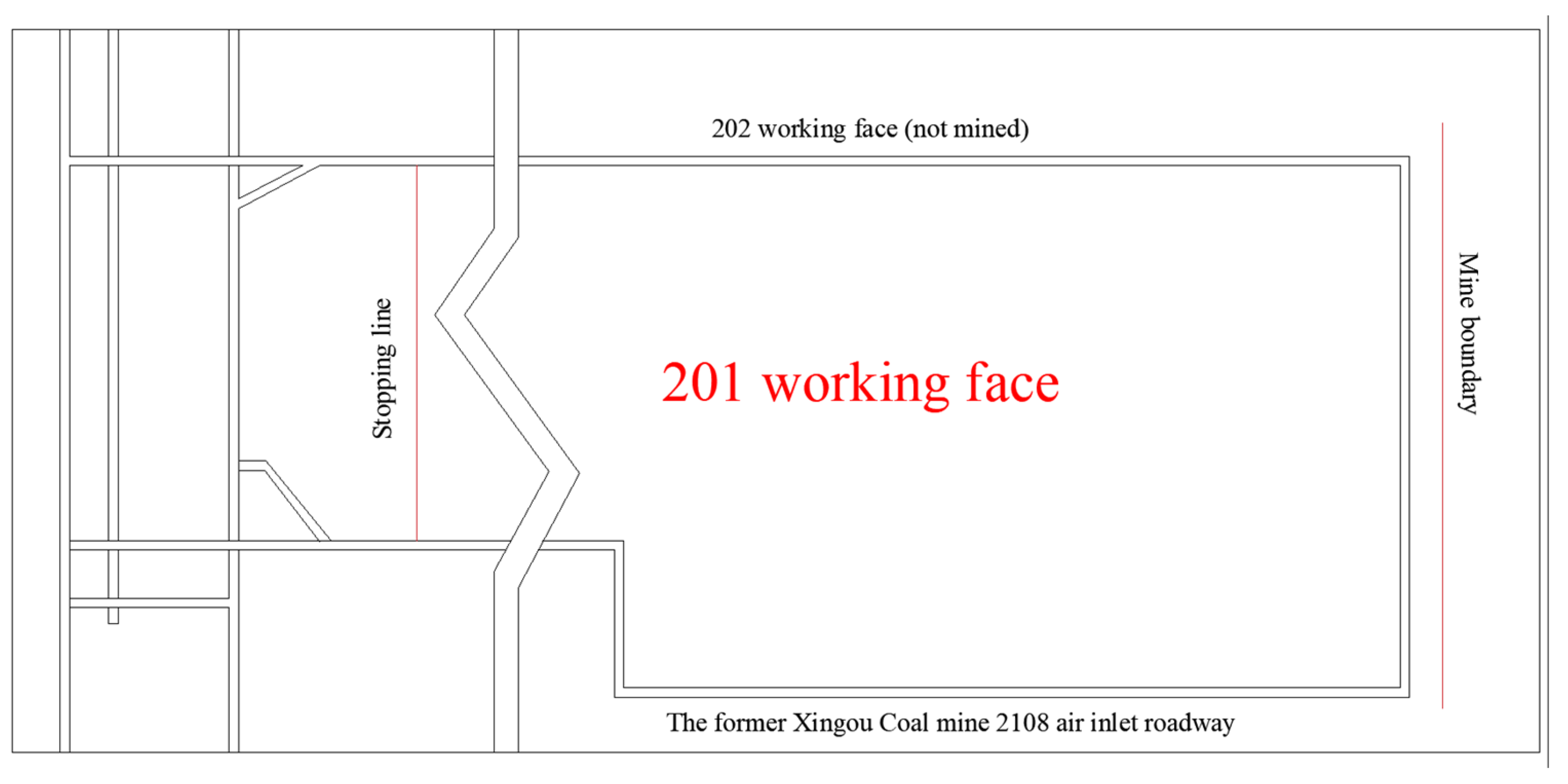
Figure 1. Layout of the 201 working face.
Sustainability 15 09003 g001
Figure 2. Coal seam histogram.
Sustainability 15 09003 g002
Figure 3. Critical layer discrimination process.
Sustainability 15 09003 g003
Figure 4. Schematic diagram of key layer fracture distance judgment.
Sustainability 15 09003 g004
Figure 5. Numerical calculation model.
Sustainability 15 09003 g005
Figure 6. The evolution process of vertical displacement of the overburden in working face: (a) advanced to 80 m; (b) advanced to 120 m; (c) advanced to 140 m; (d) advanced to 170 m; (e) advanced to 190 m; (f) advanced to 300 m.
Sustainability 15 09003 g006aSustainability 15 09003 g006b
Figure 7. Dynamic development characteristics of mining-induced overburden fracture and water-conducting fractures: (a) advanced to 100 m; (b) advanced to 130 m; (c) advanced to 160 m; (d) advanced to 190 m; (e) advanced to 220 m; (f) advanced to 260 m.
Sustainability 15 09003 g007aSustainability 15 09003 g007b
Figure 8. Schematic diagram of transient electromagnetic construction of the 201 working face: (a) schematic diagram of measuring point layout space; (b) layout diagram of measuring points.
Sustainability 15 09003 g008
Table 1. Table of mechanical parameters of rock strata.
Advancing Distance/mDevelopment Rule of Water-Conducting FractureHeight of Water-Conducting Fracture/m
10The direct roof collapsed, the basic roof was stable, and the water-conducting fracture zone did not develop upward.3.30
20The direct roof collapsed, the basic roof was stable, and the water-conducting fracture zone did not develop upward.3.30
30The basic roof was broken, and the water-carrying fracture zone developed upward to the fourth stratum.13.44
60The basic roof was broken, and the water-carrying fracture zone developed upward to the fifth stratum.28.08
100The water-conducting fracture zone continues to develop to the sixth stratum and still is stable35.72
Table 2. Mechanical parameters of the rock mass.
StrataBulk Modulus
/GPa
Shear Modulus
/GPa
Density
/kg·m−3
Cohesion /MPaTensile Strength /MPaInternal Friction Angle/°Dilatancy Angle
Medium sandstone16.77.727005.63.52915
Mudstone104.6227503.7633215
Siltstone14.26.525204.363.23415
Coal5.22.7821002.41.282515
Fine sandstone6.574.5327505.93.93815
Table 3. Mechanical parameters of joints.
StrataNormal Stiffness
/GPa
Shear
Stiffness
/GPa
Cohesion
/MPa
Tensile
Strength
/MPa
Internal
Friction
Angle/°
Medium sandstone60.045.00.6110.410
Mudstone53.254.20.465.513
Siltstone54.063.20.639.218
coal3.23.40.132.310
Fine sandstone87.785.30.9117.927
Table 4. Geophysical anomaly area and explanation.
Detect
Roadway
Abnormal Area
Number
Location of the Abnormal AreaDistance of the Abnormal Point from the Roadway
Location (m)
Explanation of the Cause
of the Anomaly
Note
201 auxiliary transport roadwayYCQ-1590–64060–100The apparent resistivity value is relatively low, and it is speculated that there may be water in the coal seam cracks.Iron pipes are hanging on the right side of the roadway, and the iron anchor net, bolt, and pallet support are on the left side.
YCQ-2910–95055–100The abnormal area is located in the empty roadway and is similar to YC08, which is presumed to be water in the low-lying area of the empty roadway or water in the seam cracks.
YCQ-31420–145050–90The range of abnormal areas is small, and it is presumed that there may be water in the coal seam cracks.
YCQ-41720–175545–80The apparent resistivity of the abnormal area is relatively low and the range is small, and it is located in an empty roadway. It is presumed that there is water accumulation in the low-lying area of the empty roadway or water in the seam cracks.
YCQ-52140–21655–95The abnormal area has a low apparent resistivity value and is close to the auxiliary transport roadway. It is presumed that there may be water in coal seam cracks or tectonic fractures.
YCQ-62200–224560–110The apparent resistivity value of the abnormal area is relatively low, adjacent to fault F2, and located in the empty roadway. It is speculated that there may be water in the fault cracks or water in the low-lying area of the empty roadway.
201 tape roadwayYCQ-7765–81545–95The apparent resistance value of the abnormal area is low, and the range is large. It is speculated that there may be water in the fault cracks.The inside of the roadway is laid with iron belt supports.
YCQ-8840–92045–100The apparent resistivity of the abnormal area is low and has a large range, and is close to YC02, which is speculated to indicate that there may be water in the structural fracture.
YCQ-9970–107540–100The abnormal area has a low apparent resistivity value and a large range and is located in the empty roadway. It is guessed that there may be water in the low-lying area or iron tools stacked in the empty roadway.
Disclaimer/Publisher’s Note: The statements, opinions and data contained in all publications are solely those of the individual author(s) and contributor(s) and not of MDPI and/or the editor(s). MDPI and/or the editor(s) disclaim responsibility for any injury to people or property resulting from any ideas, methods, instructions or products referred to in the content.