1. Introduction
In recent decades, the world has abruptly shifted its focus from fossil fuels to renewable energy sources (RESs) due to increased environmental concerns, limitations of existing energy sources, and growing global demand for electricity. Wind electric power is emerged as a typical source of clean and cost-effective energy in recent years. The offshore wind market grew by 27.8% annually between 2011 and 2020 [
1]. Europe is projected to have 300 GW of wind energy installed by 2030, with 120 GW from offshore wind power projects [
2]. In the U.S., 40% of total electricity is expected to come from RESs by 2030, with half generated by wind turbine generators [
3]. Both onshore and offshore wind farms (OWFs) can provide wind energy. As most areas with high wind power generation capacity have already been utilized globally, modern OWFs are located further from onshore grids have been developed. OWFs are favored due to their higher and more consistent wind energy potential.
For the integration and transmission of electrical power from OWFs to onshore AC grids, a HVDC transmission system is preferred over a high voltage alternating current (HVAC) system. HVDC is considered a promising technology due to its numerous advantages, including:
Lower per-km capacitance compared to the high per-km capacitance in HVAC, resulting in fewer power losses,
Ability to interconnect asynchronous systems with different frequencies and voltage ratings,
Ability to transmit power over long distances,
Preference for underwater transmission of electrical power from OWFs to onshore AC networks.
While HVDC transmission systems offer several advantages such as efficient long-distance transmission and interconnection of asynchronous grids, they also have certain disadvantages. First, HVDC systems require complex and expensive converter stations at both ends of the transmission line, contributing to high initial costs. These converter stations also demand specialized technical expertise for operation and maintenance. Second, the conversion process from AC to DC and vice versa leads to power losses, although these are typically lower than in AC systems. Third, HVDC systems are less flexible in terms of routing power to intermediate points (tap-changing), which is more easily achieved with AC systems. Fourth, under fault conditions, HVDC can be challenging to protect due to the lack of natural current zero-crossings found in AC systems. Lastly, the technology for HVDC circuit breakers is still in the developmental phase, which could pose reliability concerns.
HVDC transmission system can be categorized in two types [
4,
5,
6,
7]. The first makes use of current source converters (CSCs), such as line-commutated converters (LCC), but LCC technology is not favored for the future power system due to its limitations, including limited reactive power control, the need for a fast communication network, and the need for external circuitry to turn on and off the semiconductor devices. The second type uses voltage source converters (VSCs), and MMC-HVDC systems are currently employed in modern OWFs due to advantages such as independent control of active and reactive power, instantaneous power reversal, DC fault current limiting, lower harmonics levels, and reduced size or no need for filter circuits [
8,
9]. For the integration of large-scale wind power, a four-terminal Zhangbei MMC-based DC grid pilot project was launched in northern China, in 2020 [
10]. Combining the benefits of LCC and MMC technologies, various hybrid HVDC schemes and converters have been proposed, including a hybrid LCC-MMC converter suggested in reference [
11]. In this hybrid converter, the LCC and MMC are connected in series on the DC side, with the MMC responsible for maintaining the WF’s AC voltage and supply commutation voltage for the LCC.
Nowadays, it is widely recognized that large WFs with ratings equivalent to those of conventional power plants cannot just trip immediately following a fault. Current grid codes require WFs to have a FRT capability, even for fault durations of up to 150 ms at zero voltage [
12]. Thus, offshore WFs must be connected to the mainland AC grids by means of MMC based HVDC transmission systems [
13]. This grid code requirement poses a challenge, as a short circuit fault at the AC side of receiving end converter station for the offshore wind MMC-HVDC system unbalances the power produced by the WF and the power transmitted by the sending end converter, leading to an excess of power that continues to charge the system’s capacitor and causing a rapid rise in DC-link voltage [
14,
15]. If no actions are taken immediately to suppress the DC-link overvoltage, it can compromise the safe and reliable operation of various power electronics equipment. Consequently, it is crucial to develop a communication-free, robust AC FRT technique that addresses both overvoltage and under voltage scenarios and can be validated through testing under various faults across the system.
Increased CC within MMCs can lead to various adverse consequences, including elevated power losses, component overheating, voltage instability, harmonic distortion, and reduced system reliability. A review of the literature highlights the necessity for control strategies that effectively address circulating currents and CVR simultaneously. In addition to proposing a communication-free enhanced FRT technique, this research work focuses on suppressing CC and addressing CVR issues.
2. Comparison with Previous Research
A large body of research is carried out to address the issue of DC link overvoltage during faults in offshore wind farms (OWFs). Four main solutions have been proposed in the literature:
It’s important to note that the solutions previously discussed primarily focus on managing DC link overvoltage, assuming that the fault originates from the receiving end converter station. However, these investigations do not attend to the issue of DC link undervoltage, in scenarios where the fault is presumed to occur at the sending end converter station. Additionally, these studies fail to consider control over internal dynamics, such as CC and CVR.
Numerous methods to suppress CC and alleviate CVR issues have been proposed by researchers. However, many of these studies focus solely on unit-level MMC without considering the broader MMC-HVDC system. For example, Reduced Switching Frequency (RSF) for capacitor voltage balancing and CC suppression in Pulse Width Modulation (PWM) modulation was proposed in [
30]. Voltage sag mitigation in MMC using a Dual Synchronous Reference Frame (SRF) was analyzed in [
31]. A Sliding Mode Control (SMC) approach for CC suppression using a second-order switching law-based super-twisting algorithm was proposed in [
32], demonstrating that SMC is faster than the Proportional Resonant (PR) controller. Ref. [
33] employed a backstepping controller to regulate CC and maintain leg voltages. Despite these advances, the research exhibits significant limitations. Notably, the lack of a comprehensive MMC-HVDC system perspective and an in-depth evaluation of the proposed control strategies’ robustness under diverse AC fault conditions may limit the applicability and effectiveness of these solutions in practical, unpredictable scenarios.
If the grid is unbalanced, sub-module (SM) CVR and CC reduction will be significantly more challenging. In case of an unbalanced AC fault, CVR and CC can be substantial and exceed set safety limits, causing the converter to trip and resulting in stability problems. Studies [
34,
35,
36,
37,
38,
39,
40,
41] have presented methods for internal dynamic control of MMC models such as CVR and CC in unbalanced grid scenarios to ensure they operate within acceptable limits. While the existing studies have primarily concentrated on mitigating CC and reducing CVR issues under unbalanced AC (asymmetrical) faults, they fall short in a crucial area of AC FRT capabilities. Specifically, these investigations have not thoroughly examined the robustness of their proposed control strategies under a range of AC fault scenarios, including both symmetrical and asymmetrical faults. This gap in research could limit the applicability of these strategies in diverse real-world circumstances.
This study addresses the aforementioned issues by effectively managing the DC voltage of the HVDC link while successfully reducing CC and CVR. A robust HVDC system requires two crucial attributes: the ability to implement AC FRT and the capacity to control internal dynamics by reducing CC and CVR. This paper introduces an improved AC FRT strategy for offshore wind-based MMC-HVDC systems, which effectively minimizes CC and CVR. The MMC-HVDC system’s conceptual design is depicted in
Figure 1, and a model of the MMC using Nearest Level Modulation (NLM) with its associated decoupled control strategy is developed and assessed using the EMTDC/PSCAD simulation tool. The proposed technique’s effectiveness is verified through testing under various fault conditions at different locations. The key contributions of this paper include:
Integration of two type 4 offshore wind generators and one type 3 generator with the onshore AC grid.
Proposal of a communication-free FRT strategy that ensures stable operation during balanced and unbalanced AC faults, effectively regulating system voltages and enabling safe post-fault recovery in various fault scenarios.
Demonstration of the proposed control algorithm’s robustness in suppressing CC and regulating capacitor voltages through testing in AC fault scenarios.
3. Wind Electric Generator Technologies
Wind generators (WGs) can be categorized into four types based on their type and the power electronics-based converters used.
Fixed-Speed Wind Generators (Type 1)
Limited Variable-speed Wind Generators (Type 2)
Variable-speed Wind Generators with Partial-Scale Converter (Type 3/DFIG)
Variable-speed Wind Generators with Full-Scale Converter (Type 4/FSC)
This paper focuses on Type 3 and Type 4 wind generators. Type 3 WGs consist of a wound rotor induction generator (WRIG) coupled to the grid through a stator, with the rotor coupled to the grid via a back-to-back (B2B) power electronics-based converter, as shown in
Figure 2a. Such generator type is also known as a doubly-fed induction generator (DFIG). To allow WGs to operate at a variable speed, the B2B converter injects active power into the grid from the rotor when the speed of rotor is over the synchronous speed and absorbs reactive power from the grid and feeds it back to the grid when the rotor speed is below the synchronous speed. The rotor-side converter (RSC) connected to the rotor helps with speed control, while the grid-side converter (GSC) compensates for the DFIG’s reactive power demand at the grid connection point [
42].
Type 4 WG employs either a squirrel-cage induction generator (SCIG), a WRIG, or a permanent magnet synchronous generator (PMSG) in offshore wind applications. This technology fully decouples the generator from the grid, improving fault response and allowing for operation over a wide speed range for improved power extraction. Unlike the DFIG turbine, which only handles 30–40% of the total power, type 4 handles the complete power output. PMGS have no rotor winding, reducing losses, improving efficiency, and decreasing the overall size of the generating unit.
Figure 2b shows a type 4 WG.
4. MMC Modeling and Energy Control
Capacitor voltage and its stored energy need to be established because this study uses DC voltage as energy storage.
Depending upon the states of the switches, the output voltage waveform is achieved and causes the capacitor to either be inserted or bypassed from the circuit.
Figure 3a shows the three-phase equivalent circuit of MMC. The single phase equivalent circuit shown in
Figure 3b serves as the foundation for the mathematical model of MMC. The results of applying Kirchhoff’s voltage law to the upper and lower loop are (1) and (2):
Various currents circulating through MMC are given as:
where the upper arm current is represented by
, and the lower arm current is represented by
. The output current is denoted by the symbol
.
A DC component and many harmonic components make up the CC. A general statement that expresses it is:
The unfavorable component
is made up of many harmonic components. Moreover, the sum of SM capacitor voltages and currents is given as:
where
C is the SM capacitance, the number of SM is denoted by
N. It should be noted that the individual SM capacitor voltage of each upper SM will be denoted by
Vcm, as shown in
Figure 3a. However,
and
indicates SM capacitor voltages in both upper and lower arms respectively. Finally,
and
are insertion index for upper and lower arms respectively. Now, the reference for arm voltages is found as:
where
and
are taken from the inner current control loop and CCSC respectively.
Sum of an equivalent capacitor and measured capacitor voltages are needed to determine the amount of energy stored in a DC capacitor. It is possible to express the typical voltage of arm capacitors as:
The aggregate equivalent capacitance is then derived to determine the total stored energy in the MMC:
Assuming no losses in the converter stations, then the total energy of the MMC can be expressed as:
Active and reactive power from DFIG:
5. Proposed System Structure
The detailed control strategy for the offshore wind-integrated MMC-HVDC system is shown in
Figure 4. The submodule topology used in this study is a half-bridge because of its simple construction and low cost. MMC 1 (grid-side converter) acts as the master station, which means it controls the DC link voltage and AC voltage. On the other hand, MMC 2 (wind-side converter) acts as the slave station in islanded mode control and controls the AC voltages and frequency of the system. To control the DC voltage, the DC link voltages are continuously monitored through a control block.
Basically, the control system has two main loops: outer loops and inner loops. The outer loop can control either active power/DC voltage or AC voltage/reactive power. The output of the outer loop, idref and iqref, is fed to the inner current control loop, which acts as the reference signal for the inner loop. The actual values of id and iq are compared with the reference signals, and the error is fed to a PI controller, which minimizes the error. Vector current control is used for the MMC. The outer loop gives udref, which is transformed from dq0 to abc0 through inverse Park and Clarke’s Transformation and is used for PWM signal generation for the MMC. A circulating current suppression controller (CCSC) is employed to minimize CC. If left uncontrolled, it can cause major reliability issues in the converter stations. The CCSC used in this research work is based on the technique mentioned in [
43], in which even-order harmonics are added to the reference signal to reduce CC and CVR simultaneously.
The choice between islanded and non-islanded control modes, defined by the linked AC source type, is a fundamental component in constructing the DC system shown in
Figure 5. The WF interconnection has chosen the islanded option. In this scenario, the inner current controller can be bypassed, and voltage and frequency control (islanded) is used [
44]. Since the frequency and phase of the AC voltage are directly controlled by the controller, the phase-locked loop (PLL) is eliminated which is an additional advantage of this strategy [
45].
To dissipate the excessive power supplied from the OWFs and to avoid the DC link overvoltage scenario, a Half-Bridge Modular Chopper is used in the proposed system, as shown in
Figure 5. Modular DC chopper topologies, which are identical to the half-bridge submodule (HBSM) or full-bridge submodule (FBSM) in the MMC, are proposed to reduce the rate of change of current (di/dt) and voltage (dv/dt) [
46]. The parameters for proposed system are mentioned in
Table 1. The detailed control strategy for the offshore wind-integrated MMC-HVDC system is shown in
Figure 5.
6. Results Discussion
An efficient FRT scheme must handle various fault scenarios. To assess the robustness of the proposed scheme, a range of fault types, including three-phase faults (LLL-G), single-line-to-ground (SLG) faults, line-to-line (LL), and double-line-to-ground (LLG) faults, are considered. However, due to paper length, this paper cannot address all possible scenarios. As a result, this section provides a comprehensive analysis of the two selected fault scenarios and the impact of CCSC on MMC and overall system parameters:
Scenario 1: The LLL-G fault occurs at the REC at t = 6.5 s and is cleared at t = 6.8 s.
Scenario 2: The SL-G fault occurs at the wind bus at t = 6.5 s and is cleared at t = 6.8 s.
Scenario 3: The effect of CC on MMC reliability and overall stability is studied. The key aim of this scenario is to validate, through appropriate results, how the CVR will increase beyond acceptable levels and cause the MMC converter station and the entire system to fail if the CC suppression mechanism fails.
6.1. Simulation Results for Scenario 1 at AC Grid Connected to MMC 1
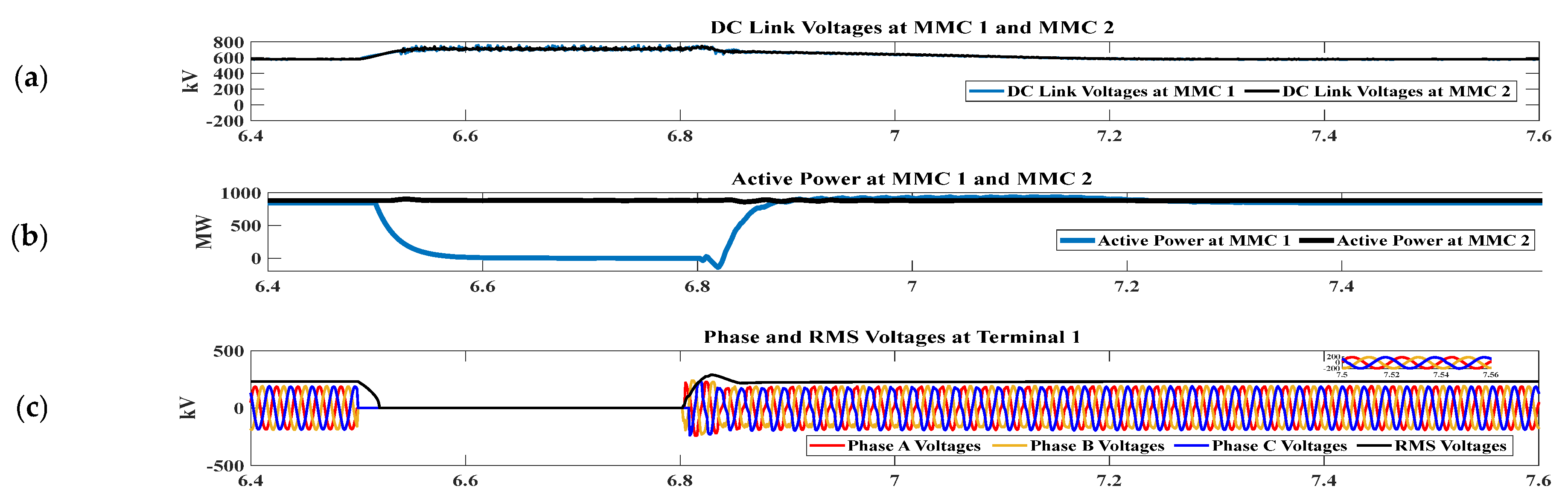
To assess the effectiveness of the proposed AC FRT techniques, a simulated LLL-G symmetrical fault is performed on the AC side of the REC station. The simulation results for both converter stations are discussed in this section. The fault lasts for a total of 0.3 s (300 ms) and is expected to occur at time t = 6.5 s and be cleared at time t = 6.8 s.
Figure 6a shows the simulation results for the DC link voltages at the receiving end converter (MMC 1) and sending end converter (MMC 2) stations. The proposed CC suppression scheme ensures smoother DC link voltages at terminals 1 and 2.
Figure 6b shows that on occurrence of fault, the active power at the REC becomes zero as soon as the maximum DC voltage (Ulim_H) is detected, while the active power supplied from the offshore wind plant is dissipated in the DC chopper as shown in
Figure 7c to avoid power imbalances between the sending and receiving sides.
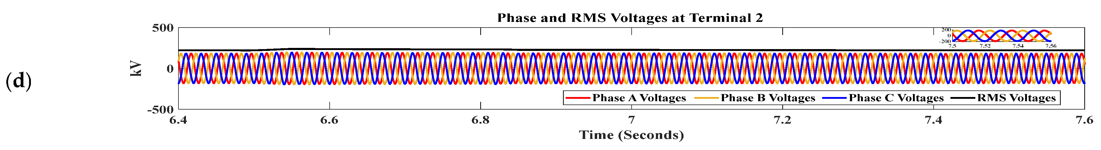
Figure 6c shows that the phase and RMS voltages at terminal 1 (connected to MMC 1) drop to zero during the fault period, however, no significant impact is observed on the phase and RMS voltages of terminal 2 (connected to MMC 2), as shown in
Figure 6d. Since the phase voltages (connected to MMC 1) drop to zero during the entire fault duration and MMC 1 station contributes limited fault current as shown in
Figure 7a, the proposed AC FRT reduces the di/dt stress on power semiconductor devices. Moreover,
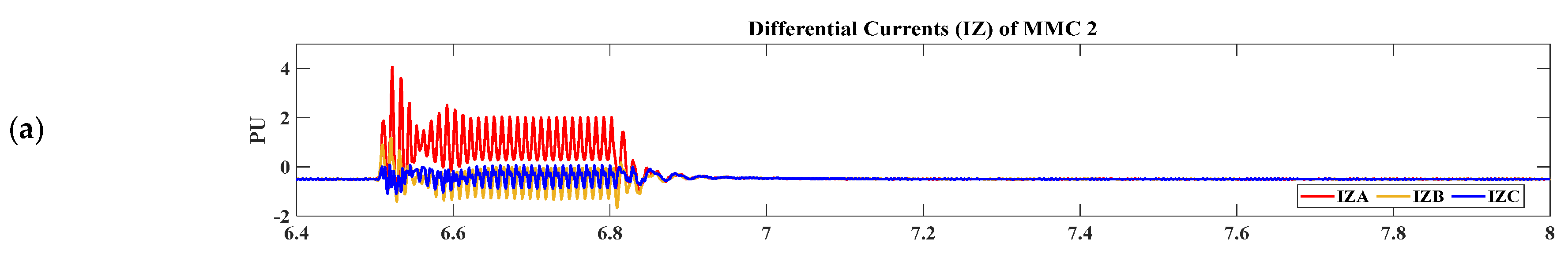
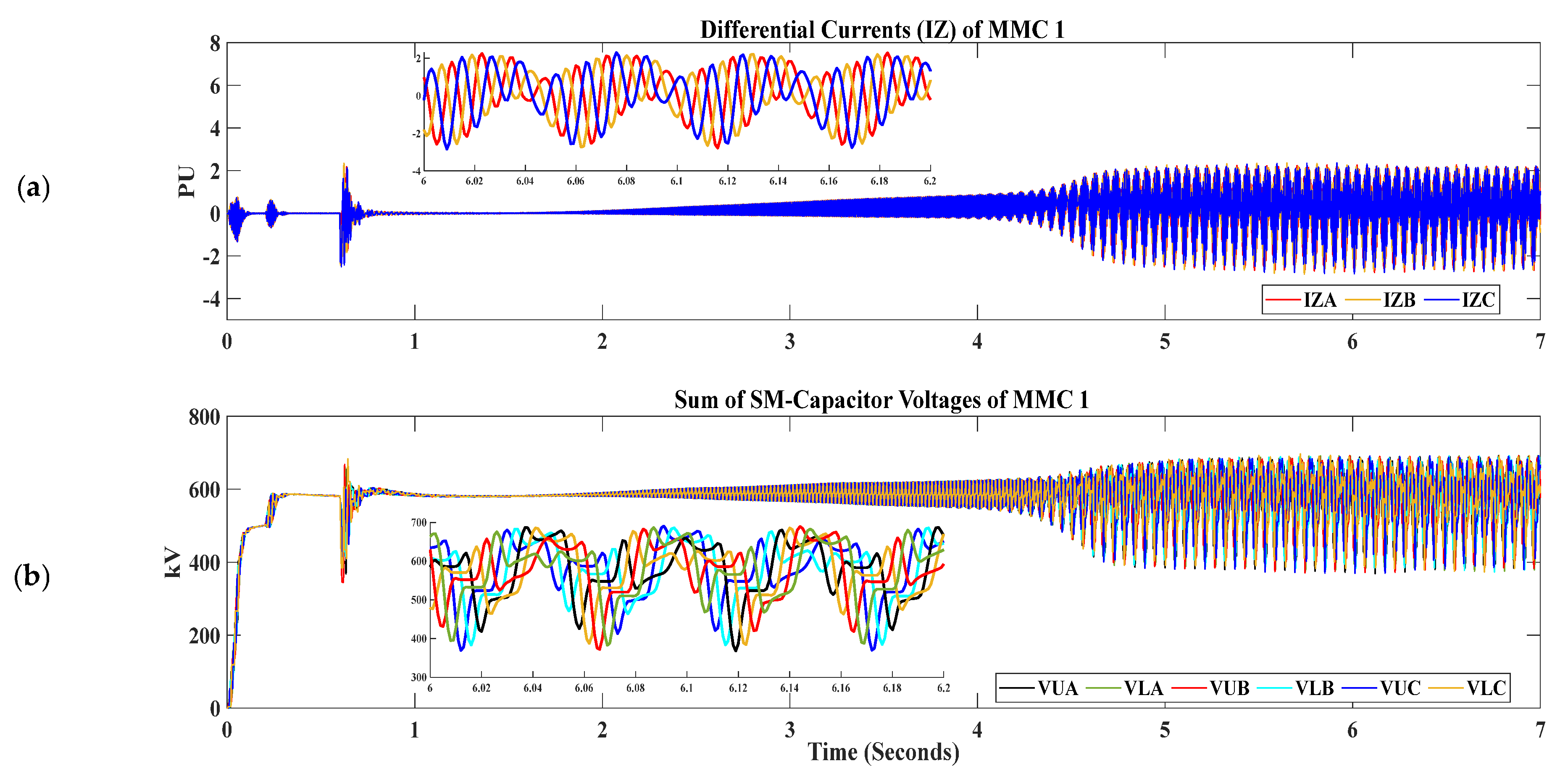
Figure 7b shows that there is no significant impact on AC side currents of MMC 2 during the entire fault. In addition to ensuring AC FRT in the offshore wind-integrated MMC-HVDC system, the proposed system also effectively handles the CC and CVR issues in the converter stations.
Figure 8a,b shows the differential current (IZ) and sum of capacitor voltages, respectively. As indicated the proposed FRT tecnhique has effectively managed the CC and CVR issues in the MMC.
6.2. Simulation Results for Scenario 2 at Wind Bus Connected to MMC 2
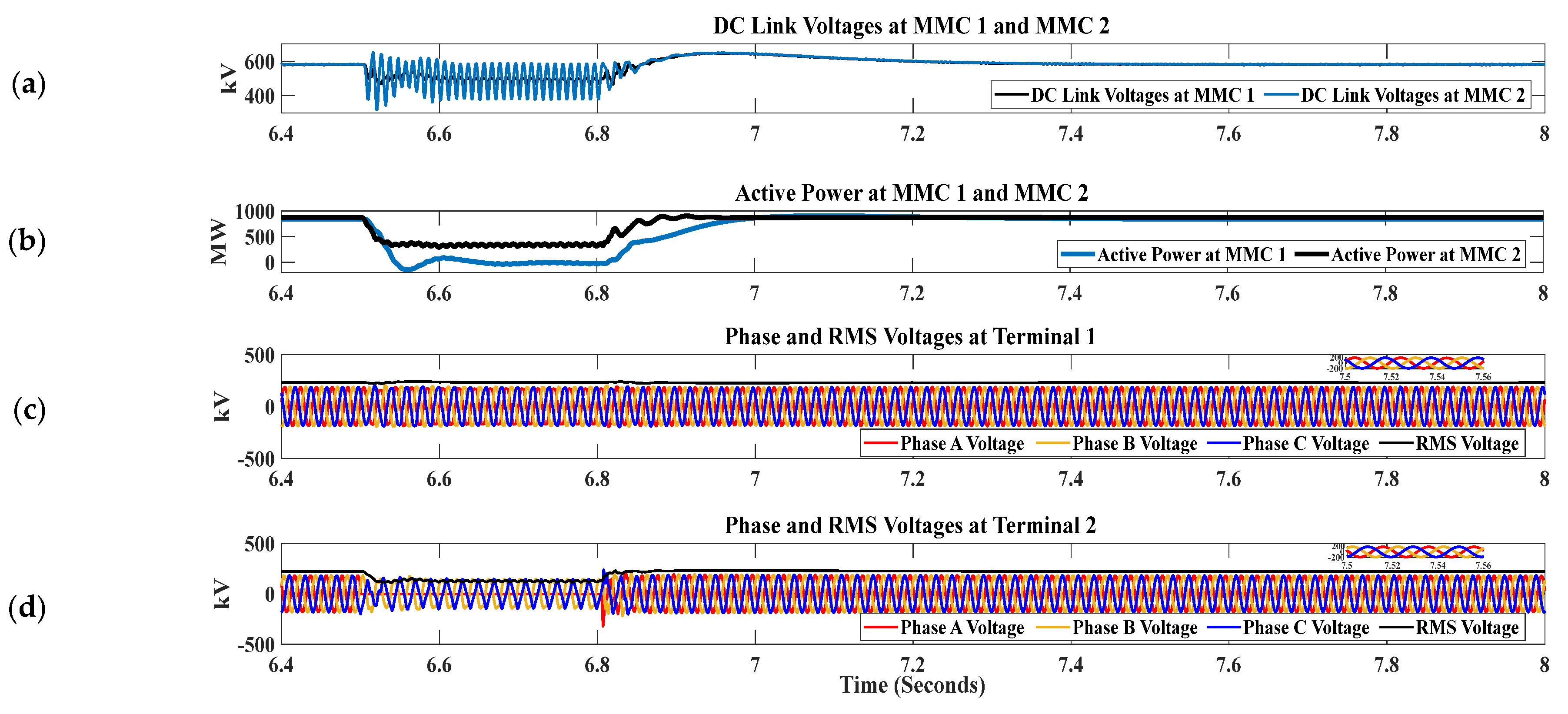
In this scenario, an L-G asymmetrical fault has been introduced at the wind bus connecting three OWFs to assess the efficacy of the proposed FRT scheme. As shown in
Figure 9a, a voltage dip has been observed at terminal 1 (grid-side). DC link voltage ripple has been observed in terminal 2 DC link voltage. These ripple components are within safe limits and do not significantly impact the performance of the converter stations.
Figure 9b and
Figure 10a show that a dip in active power and AC side currents has been observed at the REC side.
Figure 9d shows that the dip in phase and RMS voltages is at the SEC converter, with one phase reduced to zero and the remaining two reduced by their peak values. There is no significant impact on phase and RMS voltages at terminal 1 (REC) as shown in
Figure 9c.
Figure 10b shows an overshoot in one phase of the AC current at the SEC side during fault and it stays within safe limits. As fault on sending end converter is considered as under-voltage fault, so there is no excessive power loss as seen in
Figure 10c. Finally,
Figure 11a,b shows the impact of the L-G fault on the internal dynamics of the SEC station. These dynamics are not disturbed to the extent that causes the converter stations to trip, and as soon as the fault is cleared, the CC and CVR return to normal values.
6.3. Scenario 3: Effect of CC on MMC Reliability and Overall Stability (CC Disabled at Both Terminals)
In this section, the impact of CCSC on MMC reliability and overall system stability is discussed. The CCSC is disabled at the start of the simulation (t = 0 s). Results show that system parameters remain within the defined range for only a few seconds. After that, a significant impact on various parameters of the offshore wind-penetrated MMC-HVDC system is observed, leading to its complete collapse. System parameters exceed acceptable levels.
Figure 12,
Figure 13,
Figure 14,
Figure 15 and
Figure 16 indicate that the system in under normal state for the first 4 s. However, after t = 4 s, ripples in the DC link voltages and active power at both terminals (connected to MMC 1 and MMC 2) are introduced and it’s no longer smooth as indicated in
Figure 12a,b.
Figure 13a,b depicts the phase and RMS voltages of MMC 1 and MMC 2. It’s clear that the phase and RMS voltages of MMC 2 are more affected than those of MMC 1 due to the disabling of CCSC. AC side currents at both converter stations distort and is no more sinusoidal after the CC has been disabled as depicted in
Figure 14a,b. Finally it can be seen that from
Figure 15 and
Figure 16 that CC and CVR significantly detoriates and is no more stable if CC is disabled at both terminals.
It is clear from the above discussion that the proposed FRT scheme effectively ensures AC FRT in various fault scenarios without causing failure or tripping of the converter stations. Additionally, the system has the capacity to quickly return to the pre-fault state once fault is cleared. Even during the fault period, the proposed scheme helps maintain the parameters of the receiving end converter and sending end converter stations within safe limits.
7. Conclusions
In conclusion, this research presents an enhanced FRT strategy for offshore wind-integrated MMC-HVDC systems, with a focus on controlling the internal dynamics of the MMC, namely CC and CVR. A communication-free FRT scheme has been proposed and substantiated through simulations on PSCAD/EMTDC, under various fault scenarios such as LLL-G and L-G faults at different locations on both sending and receiving ends. The proposed FRT scheme outperforms in diverse fault scenarios, ensuring internal parameters such as CC, CVR, and DC link voltages remain within safe limits. Quantitative analysis reveals smoother DC link voltages at terminals 1 and 2, signifying the effectiveness of the proposed CC suppression scheme. Further, the proposed AC FRT technique successfully mitigates di/dt stress on power semiconductor devices. Moreover, it effectively handles the CC and CVR issues. Conversely, when CCSC is disabled, significant deterioration in system parameters occurs, leading to system collapse, highlighting the importance of CCSC in maintaining system stability and reliability. Therefore, the proposed FRT strategy not only guarantees robust performance during various AC faults but also effectively manages CC and CVR issues, contributing significantly to enhancing the reliability and stability of offshore wind-integrated MMC-HVDC systems. The results highlight the practical applicability and added value of the proposed strategy, marking a crucial step forward in the field of offshore wind power generation.
Author Contributions
Conceptualization, J.B.S.; Methodology, J.B.S.; Validation, M.A.; Formal analysis, J.B.S.; Resources, S.I. and M.A.; Writing—original draft, D.K.; Visualization, D.K.; Supervision, J.B.S.; Project administration, F.A.C.; Funding acquisition, S.I. and M.A. All authors have read and agreed to the published version of the manuscript.
Funding
This research received no external funding.
Institutional Review Board Statement
Not applicable.
Informed Consent Statement
Not applicable.
Data Availability Statement
Not applicable.
Acknowledgments
This work was supported by the Researchers Supporting Project number (RSP2023R467), King Saud University, Riyadh, Saudi Arabia.
Conflicts of Interest
The authors declare no conflict of interest.
Abbreviations
| Circulating Current | CC |
| Capacitor Voltage Ripple | CVR |
| Modular Multilevel Converter | MMC |
| High Voltage Direct Current | HVDC |
| High Voltage Alternating Current | HVAC |
| Offshore Wind Power Plant | OWPP |
| Fault Ride through | FRT |
| Renewable Energy Sources | RESs |
| Current Source Converter | CSC |
| Voltage Source Converter | VSC |
| Line Commutated Converter | LCC |
| Synchronous Reference Frame | SRF |
| Nearest Level Modulation | NLM |
| Phase Locked Loop | PLL |
| Current in Upper Arm of MMC | |
| Current in Lower Arm of MMC | |
| MMC Upper Arm Voltages | |
| MMC Lower Arm Voltages | |
| MMC Output Current | |
| Capacitance | C |
| SM Capacitor Voltages in Upper Arm | |
| SM Capacitor Voltages in Lower Arm | |
| Arm Inductance | |
References
- Ali, S.; Badar, J.; Akhter, F.; Bukhari, S.S.H.; Ro, J.-S. Real-time controller design test bench for high-voltage direct current modular multilevel converters. Appl. Sci. 2020, 10, 6004. [Google Scholar] [CrossRef]
- Ali, S.; Soomro, J.B.; Mughal, M.; Chachar, F.A.; Bukhari, S.S.H.; Ro, J.-S. Power quality improvement in HVDC MMC with modified nearest level control in real-time HIL based setup. IEEE Access 2020, 8, 221712–221719. [Google Scholar] [CrossRef]
- Chandio, R.H.; Chachar, F.A.; Soomro, J.B.; Ansari, J.A.; Munir, H.M.; Zawbaa, H.M.; Kamel, S. Control and protection of MMC-based HVDC systems: A review. Energy Rep. 2023, 9, 1571–1588. [Google Scholar] [CrossRef]
- Soomro; Badar, J.; Akhtar, F.; Hussain, R.; Ansari, J.A.; Munir, H.M. A detailed review of MMC circuit topologies and modelling issues. Int. Trans. Electr. Energy Syst. 2022, 2022, 8734010. [Google Scholar]
- Meisingset, M.; Golé, A.M. A comparison of conventional and capacitor commutated converters based on steady-state and dynamic considerations. IEEE Conf. Publ. 2002, 485, 49–54. [Google Scholar] [CrossRef]
- Chen, J.; Lie, T.T.; Vilathgamuwa, D.M. Enhancement of power system damping using VSC-based series connected FACTS controllers. IEE Proc. Commun. 2003, 150, 353–359. [Google Scholar] [CrossRef]
- Zhong, Q.; Zhang, Y.; Lin, L.; Chen, Q.; Wu, Z. Study of HVDC light for its enhancement of AC/DC interconnected transmission systems. In Proceedings of the 2008 IEEE Power and Energy Society General Meeting-Conversion and Delivery of Electrical Energy in the 21st Century, Pittsburgh, PA, USA, 20–24 July 2008; IEEE: Piscataway, NJ, USA, 2008; pp. 1–6. [Google Scholar] [CrossRef]
- Soomro, J.B.; Akhter, F.; Ali, S.; Bukhari, S.S.H.; Sami, I.; Ro, J.-S. Modified Nearest Level Modulation for Full-Bridge Based HVDC MMC in Real-Time Hardware-in-Loop Setup. IEEE Access 2021, 9, 114998–115005. [Google Scholar] [CrossRef]
- Atsukawa, T.; Masada, E.; Miyatake, M.; Shutoh, K. Control and performance of DC transmission system with self-Commutated converters without transformers. In Proceedings of the IPEMC 2000. Third International Power Electronics and Motion Control Conference, Beijing, China, 15–18 August 2000; IEEE: Piscataway, NJ, USA, 2000; Volume 2, pp. 862–867. [Google Scholar] [CrossRef]
- Xiang, W.; Yang, S.; Adam, G.P.; Zhang, H.; Zuo, W.; Wen, J. DC Fault Protection Algorithms of MMC-HVDC Grids: Fault Analysis, Methodologies, Experimental Validations, and Future Trends. IEEE Trans. Power Electron. 2021, 36, 11245–11264. [Google Scholar] [CrossRef]
- Lin, W.; Wen, J.; Yao, M.; Wang, S.; Cheng, S.; Li, N. Series VSC-LCC converter with self-commutating and dc fault blocking capabilities. In Proceedings of the 2014 IEEE PES General Meeting|Conference & Exposition, National Harbor, MD, USA, 27–31 July 2014; IEEE: Piscataway, NJ, USA, 2014; pp. 1–5. [Google Scholar] [CrossRef]
- Soomro, J.; Shah, F.; Soomro, S.A.; Faheem, A.C.; Ali, S. Comparative Analysis of Modular Multilevel Converter with Cascaded H Bridge Inverter using Five, Seven and Nine levels. Int. J. Recent Technol. Eng. 2019, 7. [Google Scholar]
- Saeedifard, M.; Iravani, R. Dynamic performance of a modular multilevel back-to-back HVDC system. IEEE Trans. Power Deliv. 2010, 25, 2903–2912. [Google Scholar] [CrossRef]
- Vrionis, T.D.; Koutiva, X.I.; Vovos, N.A.; Giannakopoulos, G.B. Control of an HVdc link connecting a wind farm to the grid for fault ride-through enhancement. IEEE Trans. Power Syst. 2007, 22, 2039–2047. [Google Scholar] [CrossRef]
- Ramtharan, G.; Arulampalam, A.; Ekanayake, J.B.; Hughes, F.M.; Jenkins, N. Fault ride through of fully rated converter wind turbines with AC and DC transmission systems. IET Renew. Power Gener. 2009, 3, 426–438. [Google Scholar] [CrossRef]
- Mohammadi, M.; Avendano-Mora, M.; Barnes, M.; Chan, J.Y. A study on Fault Ride-Through of VSC-connected offshore wind farms. In Proceedings of the 2013 IEEE Power & Energy Society General Meeting, Vancouver, BC, Canada, 21–25 July 2013; IEEE: Piscataway, NJ, USA, 2013; pp. 1–5. [Google Scholar] [CrossRef]
- Wu, S.; Qi, L.; Jia, W.; Zhu, Y.; Zhang, X.; Guo, X.; Pan, X. A Modular Multilevel Converter with Integrated Energy Dissipation Equipment for Offshore Wind VSC-HVDC System. IEEE Trans. Sustain. Energy 2022, 13, 353–362. [Google Scholar] [CrossRef]
- Qi, L.; Wu, S.; Zhang, X.; Zhang, M.; Liu, C.; Wang, H.; Wu, L. A Low-Cost DC Chopper with Coupling Transformer for Offshore Wind VSC-HVdc System. IEEE Trans. Power Electron. 2022, 37, 4979–4984. [Google Scholar] [CrossRef]
- Li, W.; Zhu, M.; Chao, P.; Liang, X.; Xu, D. Enhanced FRT and postfault recovery control for MMC-HVDC connected offshore wind farms. IEEE Trans. Power Syst. 2019, 35, 1606–1617. [Google Scholar] [CrossRef]
- Giddani, O.A.; Adam, G.P.; Anaya-Lara, O.; Burt, G.; Lo, K.L. Control strategies of VSC-HVDC transmission system for wind power integration to meet GB Grid Code requirements. In Proceedings of the SPEEDAM 2010, Pisa, Italy, 14–16 June 2010; IEEE: Piscataway, NJ, USA, 2010; pp. 385–390. [Google Scholar] [CrossRef]
- Kirakosyan, A.; El Moursi, M.S.; Khadkikar, V. Fault ride through and grid support topology for the VSC-HVDC connected offshore wind farms. IEEE Trans. Power Deliv. 2017, 32, 1592–1604. [Google Scholar] [CrossRef]
- Pinto, R.T.; Bauer, P.; Rodrigues, S.F.; Wiggelinkhuizen, E.J.; Pierik, J.; Ferreira, B. Strategy for Grid Integration of Offshore Wind Energy Systems through MTDC Network. IEEE Trans. Ind. Electron. 2011, 60, 1–13. [Google Scholar]
- Adam, G.P.; Ahmed, K.H.; Finney, S.J.; Williams, B.W. AC fault ride-through capability of a VSC-HVDC transmission systems. In Proceedings of the 2010 IEEE Energy Conversion Congress and Exposition, Atlanta, GA, USA, 12–16 September 2010; IEEE: Piscataway, NJ, USA, 2010; pp. 3739–3745. [Google Scholar] [CrossRef]
- Ma, H.; Ping, M.; Li, D.; Yang, M.; Liu, X.; Zhou, Y. Optimized AC fault ride-through strategy for back-to-back VSC-HVDC system. In Proceedings of the 2020 IEEE 4th Conference on Energy Internet and Energy System Integration (EI2), Wuhan, China, 30 October–1 November 2020; IEEE: Piscataway, NJ, USA, 2020; pp. 794–799. [Google Scholar] [CrossRef]
- Nakajima, T.; Irokawa, S. A control system for HVDC transmission by voltage sourced converters. In Proceedings of the 1999 IEEE Power Engineering Society Summer Meeting. Conference Proceedings, Edmonton, AB, Canada, 18–22 July 1999; IEEE: Piscataway, NJ, USA, 1999; Volume 2, pp. 1113–1119. [Google Scholar] [CrossRef]
- Xu, L.; Member, S.; Yao, L.; Sasse, C. Grid integration of large DFIG-based wind farms using VSC Transmission. IEEE Trans. Power Syst. 2007, 22, 976–984. [Google Scholar] [CrossRef]
- Feltes, C.; Wrede, H.; Koch, F.W.; Erlich, I. Enhanced fault ride-through method for wind farms connected to the grid through VSC-based HVDC transmission. IEEE Trans. Power Syst. 2009, 24, 1537–1546. [Google Scholar] [CrossRef]
- Oguma, K.; Akagi, H. Low-Voltage-Ride-Through (LVRT) Control of an HVDC Transmission System Using Two Modular Multilevel DSCC Converters. IEEE Trans. Power Electron. 2017, 32, 5931–5942. [Google Scholar] [CrossRef]
- Cui, S.; Lee, H.J.; Jung, J.J.; Lee, Y.; Sul, S.K. A comprehensive AC side single line to ground fault ride through strategy of a modular multilevel converter for HVDC system. In Proceedings of the 2015 IEEE Energy Conversion Congress and Exposition (ECCE), Montreal, QC, Canada, 20–24 September 2015; IEEE: Piscataway, NJ, USA, 2015; pp. 5378–5385. [Google Scholar] [CrossRef]
- Tu, Q.; Xu, Z.; Xu, L. Reduced Switching-frequency modulation and CCsuppression for modular multilevel converters. IEEE Trans. Power Deliv. 2011, 26, 2009–2017. [Google Scholar] [CrossRef]
- Muhammad, F.; Rasheed, H.; Ali, I.; Alroobaea, R.; Binmahfoudh, A. Design and Control of Modular Multilevel Converter for Voltage Sag Mitigation. Energies 2022, 15, 1681. [Google Scholar] [CrossRef]
- Uddin, W.; Zeb, K.; Adil Khan, M.; Ishfaq, M.; Khan, I.; Islam, S.U.; Kim, H.-J.; Park, G.S.; Lee, C. Control of output and CCof modular multilevel converter using a sliding mode approach. Energies 2019, 12, 4084. [Google Scholar] [CrossRef]
- Din, W.U.; Zeb, K.; Ishfaq, M.; Islam, S.U.; Khan, I.; Kim, H.J. Control of internal dynamics of grid-connected modular multilevel converter using an integral backstepping controller. Electronics 2019, 8, 456. [Google Scholar] [CrossRef]
- Wang, S.; Teodorescu, R.; Chaudhary, S.K. CVRreduction methods of modular multilevel converter under unbalanced fault conditions: A comparison. In Proceedings of the 2018 IEEE International Power Electronics and Application Conference and Exposition (PEAC), Shenzhen, China, 4–7 November 2018; IEEE: Piscataway, NJ, USA, 2018; pp. 1–6. [Google Scholar]
- Wang, S.; Bao, D.; Gontijo, G.; Chaudhary, S.; Teodorescu, R. Modeling and Mitigation Control of the Submodule-CVRof a Modular Multilevel Converter under Unbalanced Grid Conditions. Energies 2021, 14, 651. [Google Scholar] [CrossRef]
- Wang, S.; Dragicevic, T.; Gontijo, G.F.; Chaudhary, S.K.; Teodorescu, R. Machine learning emulation of model predictive control for modular multilevel converters. IEEE Trans. Ind. Electron. 2020, 68, 11628–11634. [Google Scholar] [CrossRef]
- Wang, S.; Dragicevic, T.; Teodorescu, R. Learning Based CVRReduction of Modular Multilevel Converters under Unbalanced Grid Conditions with Different Power Factors. In Proceedings of the 2020 IEEE 11th International Symposium on Power Electronics for Distributed Generation Systems (PEDG), Dubrovnik, Croatia, 28 September–1 October 2020; IEEE: Piscataway, NJ, USA, 2020; pp. 531–535. [Google Scholar]
- Wang, S.; Dragicevic, T.; Gao, Y.; Teodorescu, R. Neural network based model predictive controllers for modular multilevel converters. IEEE Trans. Energy Convers. 2020, 36, 1562–1571. [Google Scholar] [CrossRef]
- Kalle, I.; Antonopoulos, A.; Harnefors, L.; Norrga, S.; Ängquist, L.; Nee, H.-P. CVRshaping in modular multilevel converters allowing for operating region extension. In Proceedings of the IECON 2011-37th Annual Conference of the IEEE Industrial Electronics Society, Melbourne, Australia, 7–10 November 2011; IEEE: Piscataway, NJ, USA, 2011; pp. 4403–4408. [Google Scholar]
- Pou, J.; Ceballos, S.; Konstantinou, G.; Agelidis, V.G.; Picas, R.; Zaragoza, J. CCinjection methods based on instantaneous information for the modular multilevel converter. IEEE Trans. Ind. Electron. 2014, 62, 777–788. [Google Scholar] [CrossRef]
- Li, J.; Konstantinou, G.; Wickramasinghe, H.R.; Townsend, C.D.; Pou, J. Capacitor voltage reduction in modular multilevel converters under grid voltages unbalances. IEEE Trans. Power Deliv. 2019, 35, 160–170. [Google Scholar] [CrossRef]
- Muhammad, F.; Rasheed, H.; Spier, D.W.; Prieto-Araujo, E.; Bellmunt, O.G. Control Design and Fault Handling Performance of MMC for MMC-Based DC Distribution System. IEEE Access 2022, 10, 126695–126711. [Google Scholar] [CrossRef]
- Hafeez, K.; Khan, S.A.; Van den Bossche, A.; Hasan, Q.U. CCReduction in MMC-HVDC System Using Average Model. Appl. Sci. 2019, 9, 1383. [Google Scholar] [CrossRef]
- Rodríguez, F.Z.P.J.; Lai, J.-S. Multilevel Inverters: A Survey of Topologies, Controls, and Applications. IEEE Trans. Ind. Electron. 2002, 49, 69–76. [Google Scholar] [CrossRef]
- Beddard, A.; Barnes, M. Modelling of MMC-HVDC systems—An overview. Energy Procedia 2015, 80, 201–212. [Google Scholar] [CrossRef]
- Xu, L.; Williams, B.W.; Yao, L. Multi-terminal DC transmission systems for connecting large offshore wind farms. In Proceedings of the 2008 IEEE Power and Energy Society General Meeting-Conversion and Delivery of Electrical Energy in the 21st Century, Pittsburgh, PA, USA, 20–24 July 2008; IEEE: Piscataway, NJ, USA, 2008; pp. 1–7. [Google Scholar] [CrossRef]
| Disclaimer/Publisher’s Note: The statements, opinions and data contained in all publications are solely those of the individual author(s) and contributor(s) and not of MDPI and/or the editor(s). MDPI and/or the editor(s) disclaim responsibility for any injury to people or property resulting from any ideas, methods, instructions or products referred to in the content. |
© 2023 by the authors. Licensee MDPI, Basel, Switzerland. This article is an open access article distributed under the terms and conditions of the Creative Commons Attribution (CC BY) license (https://creativecommons.org/licenses/by/4.0/).


 ,
, 


