Article

4E Transient Analysis of a Solar-Hybrid Gas-Turbine Cycle Equipped with Heliostat and MED

by
Ramin Ghasemiasl
1,
Hossein Dehghanizadeh
1,
Mohammad Amin Javadi
1,* and
Mohammad Abdolmaleki
2,3
1
Department of Mechanical Engineering, West Tehran Branch, Islamic Azad University, Tehran 14687-63785, Iran
2
Department of Civil and Mechanical Engineering, Technical University of Denmark, 2800 Kgs. Lyngby, Denmark
3
KASMA, Sharif Advanced Technologies Center, Tehran 11155-9161, Iran
*
Author to whom correspondence should be addressed.
Sustainability 2023, 15(11), 8792; https://doi.org/10.3390/su15118792
Submission received: 6 April 2023 / Revised: 15 May 2023 / Accepted: 24 May 2023 / Published: 30 May 2023

Abstract

:
The current study investigates a cogeneration cycle of power and freshwater integrated with a solar system. The solar system is of the heliostat type, which is considered to preheat the inlet air in the combustion chamber of a 25-MW gas turbine. The waste heat of the turbine output stream is used to produce freshwater. Parameters such as the ambient temperature and solar irradiance significantly affect the system’s performance; hence, all analyses, including those pertaining to energy, exergy, economics, and environment, were conducted transiently, with a one-hour time step throughout the year so that the impacts of these effective parameters could be examined. Besides the analysis assuming a constant mass flow rate for the air entering the compressor, the calculations were repeated with the assumption of a constant volumetric flow rate to evaluate the cycle in the same conditions as those of natural gas power plants. Given the constant volumetric flow rate, for every 10-degree increase in temperature, the compressor power consumption decreased by approximately 2%. Moreover, a sensitivity analysis of the cycle performance in terms of ambient temperature was performed, and the corresponding results are presented. Finally, some correlations are presented to estimate variations in compressor power consumption and net turbine power due to temperature variations. The results demonstrate that in Bushehr, Iran, every one-degree increase in ambient temperature leads to an approximately 0.67 percentage decrease in net-generated power. In the end, the performance of the cycle was investigated under climatic conditions and solar irradiation intensities in several cities in Iran and some cities in different countries in which heliostat power plants have already been established. The results obtained in these cities were compared; it was concluded that the lowest annual cost of electricity generation is related to Isfahan in Iran, which reduces the cost of electricity generation by more than 20% (2.32 Cents/kWh) compared to the base cycle.

1. Introduction

Access to clean water and a reliable source of energy are two essential requirements for human beings. Global water demand is steadily rising and is expected to grow from 4600 in 2016 to 6000 by 2030 [1]. Additionally, based on statistics reported by UNICEF and the World Health Organization (WHO) in 2023, almost 2.2 billion people do not have access to potable water. Furthermore, the rate of energy consumption is drastically increasing to the extent that primary energy consumption in 2017 was approximately 5.48 times that of 1950 [2]. As power generation continues to rise, so do the levels of harmful pollutants being emitted. Hence, systems that provide both energy and potable water and simultaneously help to lessen pollutant emissions are considered a superb sustainable solution.
One of the best approaches for desalinating water is utilizing unavoidable waste heat released into the atmosphere at high temperatures. This can be achieved by capturing the exhaust from gas turbines and using it as the heat source for a multiple-effect distillation (MED) process. Some studies [3,4,5,6,7] have already evaluated the performance of cycles that include MED with a steam ejector refrigerator (SER) and are fed by waste heat from gas turbines. These articles have examined these cycles from various perspectives and have demonstrated their effectiveness in different ways. Cipollina [8] proposed a model that addresses most aspects, having limited the formulas of previous models, using used a robust process simulator based on the gPROMS (general PROcess Modelling System) equations to run the system model based on available data from a MED-TVC unit located in Trapani, Sicily (Italy). The outcomes they obtained indicated that such models can effectively depict the system’s dynamic response in relation to all its factors, making it a valuable resource for forecasting temporary operations and designing control systems for MED-TVC facilities. Elsayed, Mohamed L., et al. [9] presented a detailed analysis of the transient and steady-state performance of a MED-TVC unit. They showed that when the system experiences sudden changes in such parameters as motive steam flow rate, flow rate, and temperature of the cooling seawater, the plant performance is severely affected. These sudden changes lead to a mimicking of the actual conditions that MED-TVC experiences. Both the steady-state and dynamic aspects of the model were validated against experimental data already published. Changes in the brine levels for all disturbances applied were slower than those in flow rates and vapor temperature. Furthermore, changing seawater salinity did not remarkably affect the total production. As to the effective parameters, Hafdhi et al. [10] focused on an exergoeconomic optimization of a DE-TVC desalination unit integrated with a phosphoric acid power plant. The results demonstrated that the inlet mass flow rate and inlet vapor pressure of the DE-TVC system affirmatively affected the GOR of the system. In their follow-up studies [11,12], they thermoeconomically analyzed four configurations of MED-TCV, namely, backward feed (BF), forward feed (FF), parallel feed (PF), and parallel/cross feed (PCF). The effect that ensued from adding a TVC to all configurations was also investigated so that the advantage of the PCF mode could be examined. The results showed that the performance of the PCF configuration was higher than that of other feed configurations; however, having the highest flow rate of the specific cooling seawater was the inevitable consequence of this configuration. The BF configuration had the lowest flow rate. Additionally, changing the input parameters led to the most considerable GOR reduction in the MED-TVC stage compared to other cases, especially in seawater cooling. In another study, You et al. [13] assessed the performance of a poly-generation system and a MED system integrated with a gas turbine and equipped with a steam ejector refrigerator; the results indicated that using gas turbines with a MED-TVC unit and heat exchangers can be efficient enough to recover exhaust waste heat based on the principle of energy cascade utilization.
In technical terms, there are multiple methods of supplying the necessary energy, including but not limited to geothermal and solar energy. For instance, Kianfard et al. [14] investigated the performance of a geothermal-based system used to cogenerate hydrogen and distilled water via thermodynamic, exergoeconomic analyses. As another example, Javadi et al. [15] proposed integrating a MED system, equipped with parabolic solar collectors with the Abadan combined cycle power plant (CCPP) so as to cogenerate power and water. By calculating changes in exergy efficiency, carbon dioxide emission, and the cost of electricity generation which ensued from adding the MED, they evaluated performance enhancement. The obtained results indicated that using the proposed cycle resulted in a 5.3% reduction in CO2 emissions and allowed the production of 20 million liters of freshwater per day. Some other methods, such as using sewage sludge from a wastewater treatment plant [16] and even interconnecting the integral pressurized water reactor (iPWRs) to develop nuclear desalination plants (NDPs) [17], have been proposed.
It is worth mentioning that providing the turbine inlet temperature (TIT) of the gas turbines necessitates a high-temperature heat source; thus, technologies such as heliostats can be helpful to preheat the airflow to near TIT [18,19]. Therefore, to reduce pollutant emissions from gas turbines, a concentrated solar power (CSP) system can be used to preheat the incoming flow to the combustion chamber, which, in turn, reduces fuel consumption and emissions. Darwish Ahmad et al. [20] first modeled the power plant ALQatrana in the Jordan power plant. Afterward, they proposed that the current active cycle could be changed to a hybrid system equipped with CSP. According to the obtained results, the proposed solar system increased power generation by 22.8%, increased productivity by 4.3%, and reduced fuel consumption by 8.4%. Using the proposed system led to a 15% reduction in CO2 emissions and an annual saving of USD 2.44 million in fuel consumption with a payback period of 5.3 years. Javadi et al. [21] proposed three different configurations of a solar power tower system to be integrated with the Abadan combined cycle power plant. These proposed configurations included preheating inlet fuel and the inlet air of the combustion chamber. The results showed that the energy and exergy efficiencies of the preheating fuel scenario were 42.56% and 39.42%, respectively. Additionally, applying this scenario reduced emissions by 8041 tons per year. The second scenario, however, seemed to be more beneficial from an economic point of view simply because preheating inlet air and reducing fuel consumption leads to an annual saving of USD 11 million and prevents 34,563 tons of emissions per year.
In order to elevate the solar contribution share, using a low-TIT gas turbine has been suggested [22]. This is because the lower the TIT is, the less fuel is needed to raise the solar-preheated air temperature up to the TIT. Nevertheless, using low-TIT turbines results in lower thermal efficiency compared to high-TIT ones. Thus, the lower the TIT, the higher the solar share. Needless to say, implementing solar towers to provide the temperature levels required by high-TIT turbines is usually not cost-effective. Some studies [23,24,25] have performed economic and environmental feasibility studies for such systems. Dube Kerme et al. [26] analyzed a poly-generation cycle equipped with a solar thermal energy system. Three different configurations were evaluated: power generation only, cogeneration power and cooling, cogeneration power and desalination, and a poly-generation system. The results showed that increasing the turbine inlet temperature improved performance, although it also reduced the total exergy destruction.
Although there has been a great deal of attention and research devoted to similar solar cycles, some yet-to-be-addressed points merit consideration. First, the impact of ambient temperature on changing the mass flow rate regarding gas turbine performance is critical, yet has often been overlooked in previous research, while, in a real gas power plant, the mass flow rate of the compressor is not constant. Rather, the volumetric flow rate remains constant. However, few studies, if any, have regarded this variable mass flow rate and its effect on important parameters such as net power, compressor power consumption, efficiency, and even the pressure ratio of the turbine under varying ambient temperatures. Therefore, it is imperative to analyze the cycle under both assumptions to gain a comprehensive understanding of gas turbine performance under different environmental conditions.
Second, some prior studies have examined multi-generation systems, but more studies are needed to dynamically investigate the performance of a MED fed directly by the waste heat of a solar-hybrid gas turbine equipped with a heliostat. Connecting the MED directly to the gas turbines increases the capacity of the MED to desalinate water. In addition, dynamic analysis of the system with a one-hour time step over the year makes it possible to evaluate the system performance in a more realistic, precise manner. Certainly, solar-powered systems can significantly reduce greenhouse gas emissions. To meet all the above requirements, including those of power generation, water desalination, and pollution reduction, a solar-hybrid gas turbine equipped with a MED, SER, and a heliostat is proposed.
In the current research, a hybrid cogeneration cycle including a gas turbine, a heliostat solar field used to preheat the air entering the combustion chamber, and a thermal desalination system to recover the waste heat from the turbine were proposed and quasi-transiently analyzed. In addition to the thermodynamic analysis, the proposed system was also investigated through exergy-economic analysis and calculating the amount of pollutant emissions. Changes in ambient temperature significantly affect the mass flow rate entering the system, and, consequently, system performance experiences remarkable variations. Since the present study considered ambient temperature variations during all hours of the year and repeated the calculations with a time step of one hour throughout the year, sensitivity analyses were performed with two different assumptions, namely, constant volumetric flow rate and constant mass flow rate. In this way, the assumptions considered are as close to reality as possible, and the results obtained from each assumption can be compared.

2. The System Considered

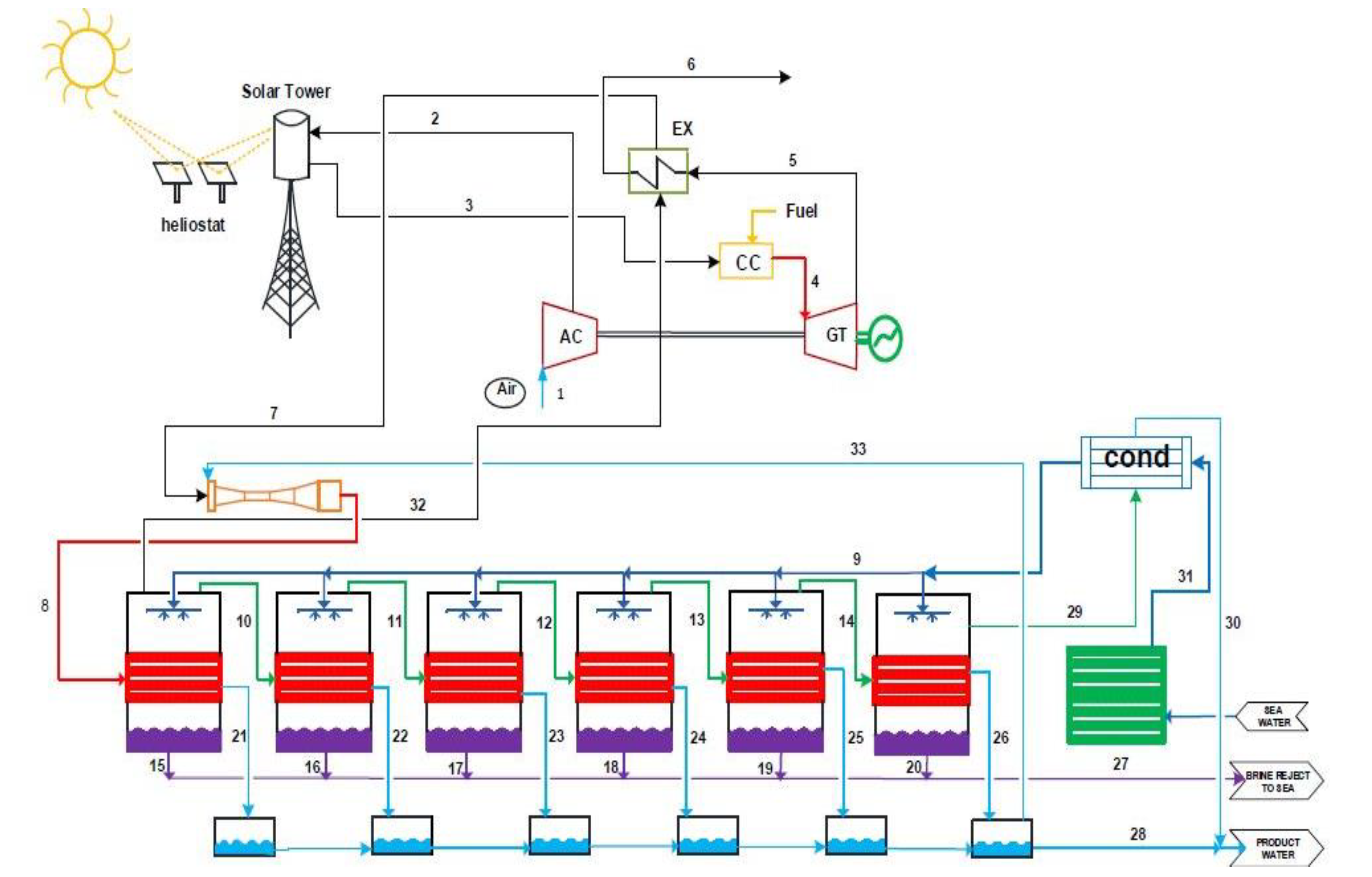
The system studied in the current research was a gas turbine equipped with a heliostat solar system, which is considered to preheat air before entering the combustion chamber. Additionally, a MED unit was designed to recover the waste heat of the turbine outflow. Figure 1 illustrates the schematic of the proposed cycle. At point 1, air enters the compressor, and its temperature goes up because of the pressure increase. The prominent additional increase in temperature, which mirrors the preheating process, occurs between points 2 and 3, where the heat exchanger is installed. Preheated air enters the combustion chamber and reaches the turbine inlet temperature (TIT) with a slight pressure drop. Hot air with a 1163-degree temperature leaves the combustion chamber (point 4) and enters the gas turbine to generate power. At point 5, the outlet flow is used to provide the required energy of the motive steam flow in a six-step desalination system. In the desalination system, the motive fluid heats up and evaporates. The heated steam enters the first stage of desalination so that the evaporation and distillation processes and, consequently, water purification are achieved.
A multi-effect desalination system comprises a multi-stage distillation process that involves the evaporation and condensation of salt water. In this process, the salt water is preheated and then sprayed onto pipes containing primary steam from a thermal power plant. Heat exchange occurs between the primary steam and salt water, causing the salt water to evaporate and resulting in the production of steam. The primary steam then loses its heat and condenses, while the resulting steam is sent to the next stage to be exchanged again. This process is repeated in six stages, with fresh water being collected from the second stage onwards, along with the primary condensed steam. This allows for the continuous production of freshwater through each stage of desalination.

3. Methodology

The analysis of the suggested cycle was performed with a one-hour time step throughout the year in a quasi-transient manner; by doing this, the cycle was evaluated at all year hours. Although the main presented results were obtained based on the weather conditions of Bushehr, some calculations were repeated under the weather conditions of different cities and then compared. In the current study, various analyses were performed, assumptions of which are explained below:
  • All processes were considered steady-state.
  • Air and exhaust gas from the combustion chamber were assumed to be ideal gas.
  • Kinetic and potential forces were not regarded in calculations.
  • Concerning conditions of the dead state, temperature and pressure were considered to be 15 °C and 100 kPa, respectively.
  • The relative pressure drop in the combustion chamber was assumed to be 0.027.
  • The turbine and compressor were assumed to be adiabatic.
  • The inlet temperature of the compressor was the same ambient temperature.
  • The steam produced in the desalinating effects was free of impurities, and the mass flows of the results were equal.
  • The direct normal irradiance (DNI) of Bushehr, having a latitude of 28.92 degrees north, a longitude of 50.84 degrees east, and an altitude of 8 m above sea level, was calculated dynamically throughout the year. Moreover, the climatic information of different cities was extracted from the Meteonorm database.
For the suggested cogeneration system, which includes the heliostat, gas turbine, and MED desalination, first, the thermodynamic equations governing the components are presented based on the first and second thermodynamic laws; afterward, the exergoeconomic analysis is conducted, and then the amount of the system pollutants are investigated and compared under different conditions. Some considered assumptions are presented in Table 1.

3.1. Thermodynamic Analysis

To thermodynamically analyze each component, equations of the first law were considered according to [27,28,29,30], as below (Table 2):

3.2. Exergy Analysis

The exergy analysis investigated the maximum usable power generation capacity in a balanced state with the environment using the second thermodynamic law and the mass conservation equation [31]. The equations of the second law for each piece of equipment were written according to [32,33], as below:
d E C V d t j = 1 T 0 T i Q ˙ i W ˙ P 0 d V C V d t + i m ˙ i e i e m ˙ e e e E ˙ x D
E ˙ x Q + i m ˙ i e x i = e m ˙ e e x e + E ˙ x w + E ˙ x D
In these equations, the subscripts i and e represent the inlet and outlet flow of the control volume, respectively. E ˙ x D represents the exergy destruction. E ˙ x Q and E ˙ x w were calculated according to Equations (3) and (4).
E ˙ x Q = ( 1 T 0 T i ) Q ˙ i
E ˙ x w = W ˙
The exergy of all flows could be obtained using Equations (5)–(9).
E ˙ = m ˙ e
E ˙ = E ˙ p h + E ˙ c h
E ˙ p h = m ˙ h h 0 T 0 s s 0
E ˙ c h = m ˙ e m i x c h
e m i x c h = i = 1 n X i e i c h + R T 0 k = 1 n X k L n X k
In the above equations, E is the exergy flux, X is the mass flow rate of the reactants, and subscripts ph and ch represent the physical and chemical exergy, respectively. Fuel exergy is calculated by Equation (10), which was presented by Ahmadi et al. [34].
ξ = e f L H V f
The impact, which was obtained by dividing the chemical exergy of the fuel (ef) by the lower heating value (LHV), is usually near 1 ( ξ C H 4 = 1.06 ). Equations used to calculate the exergy efficiency and exergy destruction are listed in Table 3.

3.3. Exergoeconomic Analysis

Exergoeconomic analysis simultaneously regards energy–exergy and economic analyses so that the actual product cost of a system can be examined. The production cost was calculated based on Equation (11) [35].
C ˙ e , k + C ˙ w , k = C ˙ q , k + C ˙ i , k + Z ˙ k
By combining the exergy equation (Equation (11)) with the economic–exergy equation (Equation (12)), Equation (13) was obtained, by which the exergy destruction cost for each component was calculated.
E x ˙ F , k = E x ˙ p , k + E x ˙ D , k + E x ˙ L , k
C ˙ p , k E x ˙ p , k = C ˙ F , k E x ˙ F , k C ˙ L , k + Z ˙ k
By eliminating E x ˙ F , k , Equation (14) was obtained.
C ˙ p , k E x ˙ p , k = C ˙ F , k E x ˙ p , k + C ˙ F , k E x ˙ L , k C ˙ L , k + Z ˙ k + C ˙ F , k E x ˙ D , k
E ˙ x D , k represents the exergy destruction rate. Assuming that the cost of the production exergy was constant, the cost of the exergy destruction was calculated by Equation (15).
C ˙ D , k = C ˙ F , k E x ˙ D , k
Although there are quite a few methods to compute the conduction cost in a power plant, the method presented by Dincer and Rosen [36] was used in the current study (Equation (16)):
Z ˙ k = Z k . C R F . φ ( N × 3600 )
where Z k , φ , and N are the cost of purchasing the kth component of the system in dollars, the maintenance factor, and the annual operating hours of the system, respectively. φ and N were considered to be 1.06 and 7446, respectively. Parameter CRF is the cost recovery factor abbreviation, which depends on the efficiency during the ith period of time and the predicted lifetime of the nth system (Equation (17)) [36].
C R F = i ( 1 + i ) n ( 1 + i ) n 1
Besides the above economic analysis, another analysis using a more common method in the power station industry was performed to estimate the cost of power generation in the gas turbine cycle. In this method, the cost of electricity production was estimated in kilowatt-hours under different conditions. To this end, the power required to generate 1 kWh of electricity was first calculated by Equation (18), called heat rate (HR).
H R = 3600 η G T
η G T , the thermodynamic efficiency of the power-generating gas cycle, could be formulated as follows:
η G T = W G T W c o m Q C C + Q H e
The fuel required to produce 1 kWh of electricity was also calculated from Equation (20).
m = L H V f u e l H R
The cost of fuel used to produce 1 kWh of energy was also easily calculated by multiplying the cost per kilogram of fuel by the mass obtained from Equation (20) (Equation (21)).
C O F = m × S

3.4. Environmental Analysis

Using fossil fuels leads to pollutant greenhouse gases such as CO, CO2, and NOx. In the present section, the amount of emissions is calculated in both the base gas cycle (without any heliostat system) and the heliostat-equipped cycle; by doing so, the effect of using the proposed heliostat system in a hybrid manner on fuel consumption is evaluated. The emission rate of these pollutant gases was calculated from Equation (22), in which AR represents the activity rate and EF is the emission factor; parameter ER, which is equal to the efficiency of the emission-reducing system, was not regarded in the current study; therefore, Equation (22) was changed to Equation (23) [37,38].
E = A R × E F × ( 1 E R 100 )
E = A R × E F
EF depends on three parameters: fuel consumption, pollutant, and process type. In the current study, natural gas was considered as fuel; CO, CO2, and NOx were considered to be pollutants. The combustion chamber process was considered as the type of process; accordingly, the corresponding emission factors, which were determined based on [39,40], were calculated as follows:
E F C O = 28 g G J
E F N O x = 70 g G J
Equation (26), presented in [34], was used to obtain the emission factor of CO2. Moreover, the net heating value (NHV) of the fuel and α were 51,600 kJ/kg and 3.67 [41], respectively. Qfuel was achieved by Equation (27).
E = Q F u e l N H V F u e l . C % 100 . α
Q F u e l = Q a u x η a u x

4. Results and Discussion

Overall, the obtained results are presented in both a daily and a monthly manner. To obtain daily results, four days of each season were determined. These four days were the 15 February, the 16 May, the 16 August, and the 15 November. It should not be left unmentioned that the daily comparisons aimed to understand the parameters’ fluctuations at different hours during the day, whereas monthly results are presented to illustrate the impact of changing environmental conditions throughout the year.

4.1. Thermodynamic Analysis

In a Brayton cycle, ambient temperature (inlet temperature to the compressor) significantly affects the compressor’s power consumption and outlet temperature. Because of the compressor outlet temperature variation, the inlet temperature to the combustion chamber changes, which, in turn, changes the fuel consumption and total turbine inlet mass flow rate; consequently, the output power also changes. Accordingly, this section investigates the effect of ambient temperature variations on the performance of the compressor, combustion chamber, and turbine.
The effects of ambient temperature variations can be investigated by two different assumptions: constant volumetric flow rate and constant mass flow rate. In academic analyses, the mass flow rate is usually assumed to be constant, but this is not the case in the power plant industry. In an actual gas power cycle, the inlet volumetric flow rate is constant, not the inlet mass flow rate. Accordingly, the analyses were performed once with the assumption of constant mass flow and again with the assumption of constant volumetric flow rate. The purpose of the following two sections is to estimate variations in compressor power consumption and power generation due to inlet temperature variation for similar cases with acceptable accuracy, without performing lengthy calculations, whether with a constant mass flow rate or with a constant volumetric flow rate.

4.1.1. Compressor Power Consumption with a Constant Mass Flow Rate

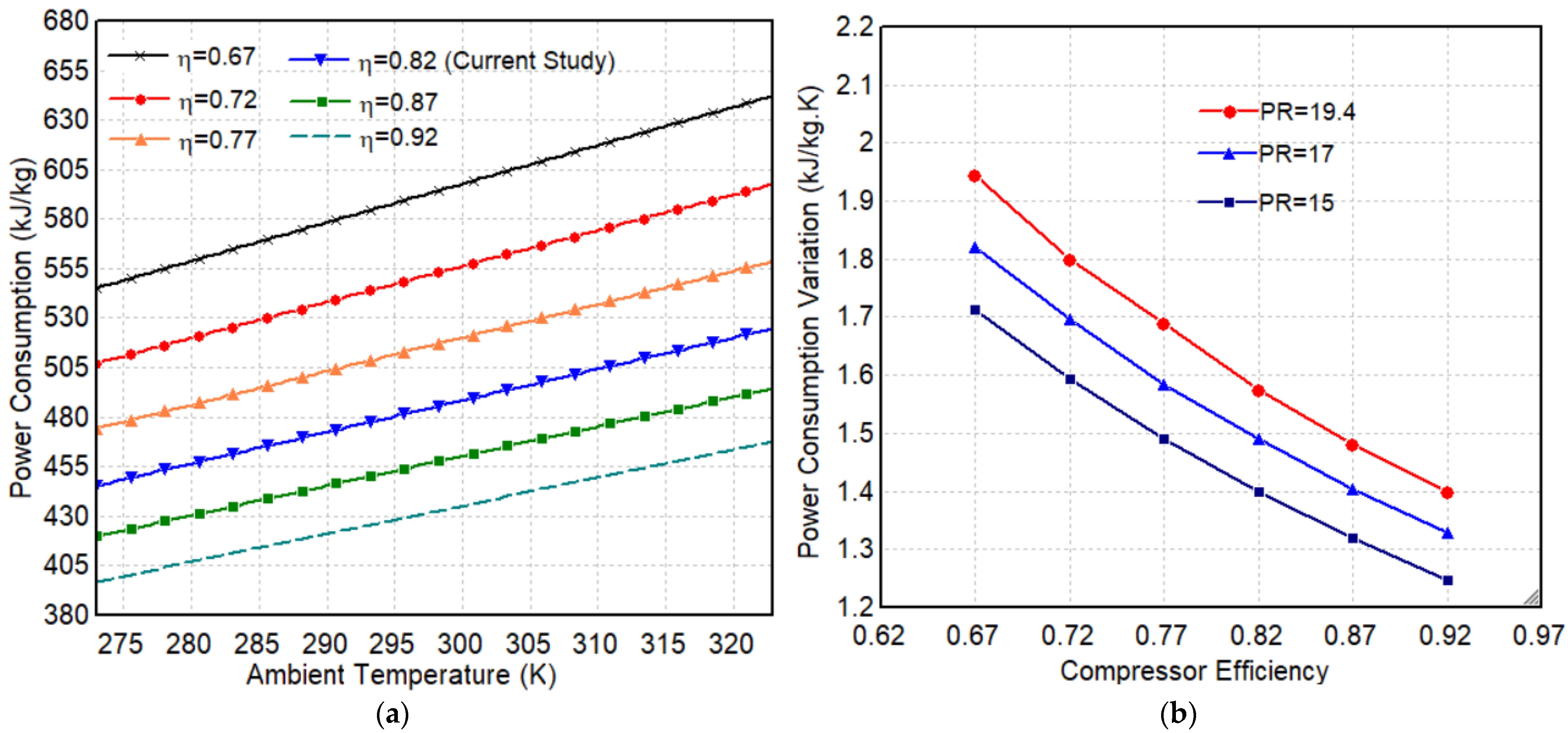
The preliminary simulation results demonstrated that for each degree of increase in compressor inlet temperature, the compressor pressure ratio (PR), determined by the turbine, decreased by approximately 0.36%. Nevertheless, assuming that the mass flow rate to the compressor and the pressure ratio were constant, increasing the ambient temperature, which was the same as the compressor inlet temperature, increased the per-unit mass power required by the compressor.
Figure 2a shows how much the power consumption of different compressors with ambient temperatures increases with a constant PR. To plot all diagrams shown in Figure 2a, ambient pressure and the PR were assumed to be 1 atm and 19.4, respectively. The amount of increase in compressor power consumption is inversely related to compressor efficiency. Since this relationship is almost linear, the slope of each diagram in Figure 2a shows the amount of change in the per-unit mass power consumption of the compressor for a one-degree ambient temperature increase. For example, the slope of the blue graph in Figure 2a is 1.58. That is, in a compressor with a pressure ratio of 19.4 and an efficiency of 0.82, for every degree of ambient temperature increase, the per-unit mass power increases by 1.58 kW. Hence, the points presented in Figure 2b were obtained by calculating the slope of the shown diagrams in Figure 2a. To be comparable and more perceivable, all required calculations were repeated with pressure ratios of 15 and 17 (Figure 2b). The vertical axis in Figure 2b illustrates the variation in power consumption for different compressors caused by a one-degree change in temperature per kilogram of air supposing, for example, that the inlet mass flow rate and pressure ratio (PR) are constant. PR and the compressor’s efficiency were 15 and 0.77, respectively. In this case, the compressor energy consumption changed by 1.5 (kJ/kg) for every one-degree change in ambient temperature (Figure 2b).

4.1.2. Compressor Power Consumption with a Constant Volumetric Flow Rate

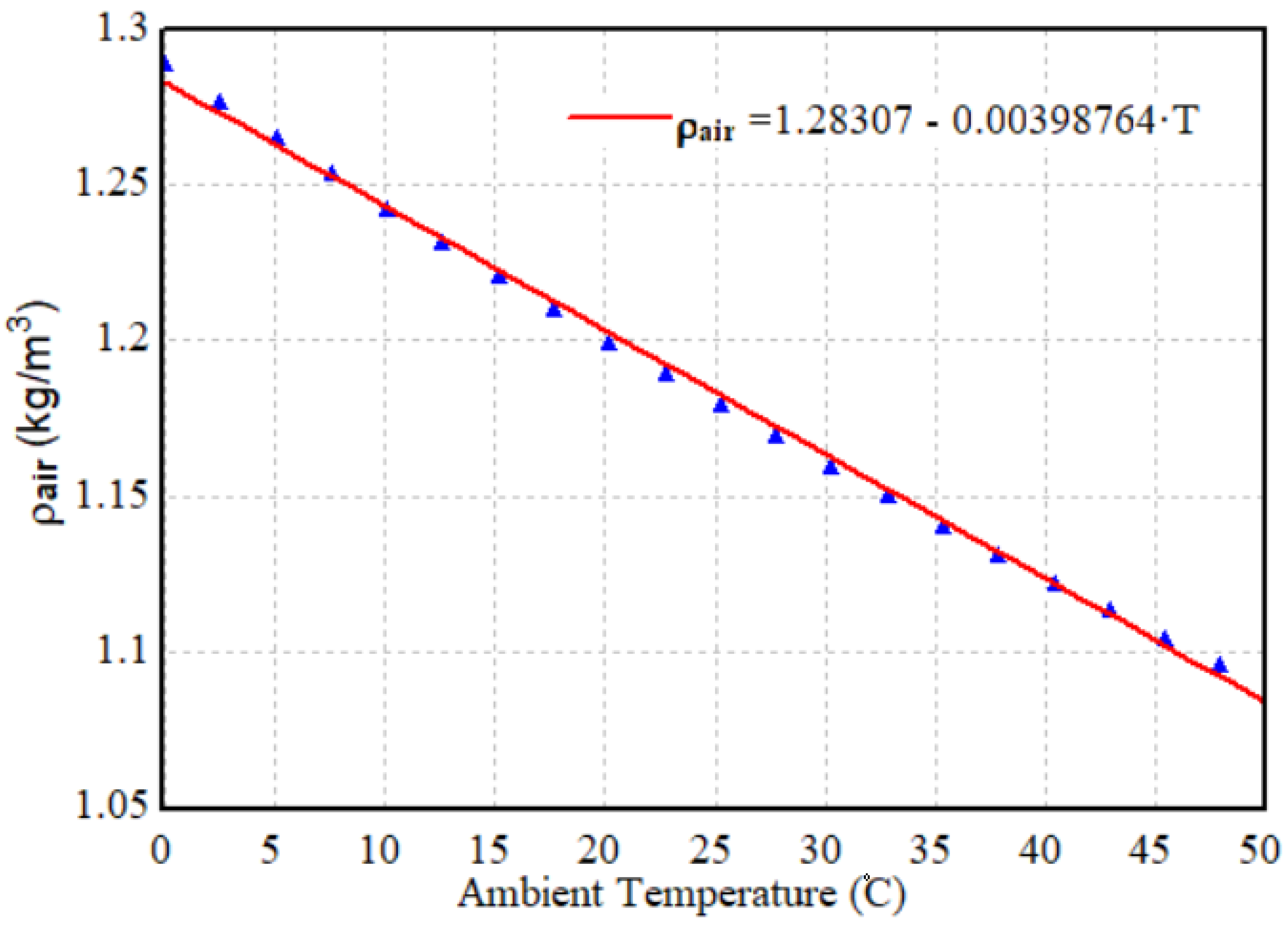
If the mass flow rate was constant, the ambient temperature increase caused an increase in compressor power consumption per unit mass and reduced power generation. This is because the compressor consumed a portion of the power generation. However, in an actual gas power plant, the trends of the results were otherwise. In actual gas power stations, the inlet volumetric flow rate is constant, not the inlet mass flow rate. When ambient temperature increases, the specific volume of the air goes up, and, in turn, the inlet mass flow rate decreases. Figure 3 illustrates the effect of temperature on the air density.
Figure 4 shows the compressor power consumption in a gas cycle with variable/constant PR, assuming the inlet volume flow rate is constant. To be simply observed, results related to efficiencies of only 0.87 and 0.82 are presented in this figure. Of course, the results of other efficiency values followed similar trends. The results show that when the volume flow rate and PR were assumed to be constant, increasing the inlet temperature resulted in a slight relative decrease in compressor power consumption, that is, the obtained trend contradicted the results’ trend of the constant mass flow rate.
Accordingly, it can be concluded that in actual conditions where the inlet volume flow rate is constant, if the ambient temperature increases, the amount of compressor power consumption reduction, which is related to the mass flow reduction, overcomes the increase in power consumption per unit mass, as shown in Figure 2a.
It is worth mentioning that the amount of power consumption reduction, even with a 30-degree temperature increase, is not very remarkable and is small compared to the initial value. However, when considering pressure ratio variations, it does not remain unremarkable (Figure 4). Equation (28) is an approximate correlation to correctly estimate pressure ratio changes due to temperature variations. This correlation was obtained by performing a sensitivity analysis in Thermoflow software (Ver: 21.0). In this correlation, ∆T indicates inlet temperature variation.
P R n e w = P R ( 1 0.0036 × T )
The higher slope of the variable-PR diagrams in Figure 2 shows that assuming the pressure ratio to be constant in the calculations can cause striking errors.
To clarify, let us assume that the compressor efficiency, as in the present case, is 0.82. In this case, if the PR is considered constant, the compressor energy consumption will decrease by approximately 0.05 kJ/m3 for every degree of temperature increase. On the other hand, if the conditions are similar to those of actual operations (constant volume flow and variable pressure ratio), compressor energy consumption increases by approximately 1.12 kJ/m3 for every degree of temperature increase.
In this regard, similar calculations were repeated for different efficiency values. By doing this, Equation (29) was obtained; this equation made it possible to estimate changes in power consumption in terms of inlet temperature variations with acceptable accuracy in the temperature range of 0 to 50 °C and efficiency range of 0.67 to 0.97. If the inlet air temperature increased ( T > 0 ), the compressor power consumption decreased ( W C o m < 0 ).
W C o m = T [ 1.14 L n η c o m 6.15 ]
Finally, in addition to the following equation, another result indicated that for every 10 °C increase in inlet temperature to the compressor, the compressor power consumption was diminished by approximately 2%.

4.1.3. Turbine Power Assuming Constant Mass and Volume Flow Rates

In this section, an analysis of total turbine power is first presented, assuming a constant mass flow rate. Although the inlet airflow to the combustion chamber was constant, an ambient temperature increase caused the inlet temperature of the combustion chamber to increase. Consequently, the combustion chamber consumed less fuel to supply the TIT, which is constant and unique for every turbine. Thus, an increase in ambient temperature leads to a decrease in the fuel mass flow rate. Additionally, since the turbine inlet mass flow rate was equal to the sum of the air and fuel mass flow rate, it can be concluded that an increase in ambient temperature reduces the turbine mass flow rate and, consequently, total turbine power. However, in fact, the turbine power reduction of the constant volumetric flow is more significant than that of the constant mass flow. This is because if the volumetric flow rate is constant, the ambient temperature increase leads to reduced air mass flow rate and, consequently, fuel mass flow rate. As in this case, both air flow and fuel consumption were reduced, the inlet flow to the turbine was drastically reduced and the total turbine power was reduced more than when using the constant mass flow mode.
The results of the sensitivity analyses performed are schematically presented in Figure 5. In this schematic, the size of the arrows represents the variations of each parameter compared to other parameters so that the variation trends are perceivable at a glance.
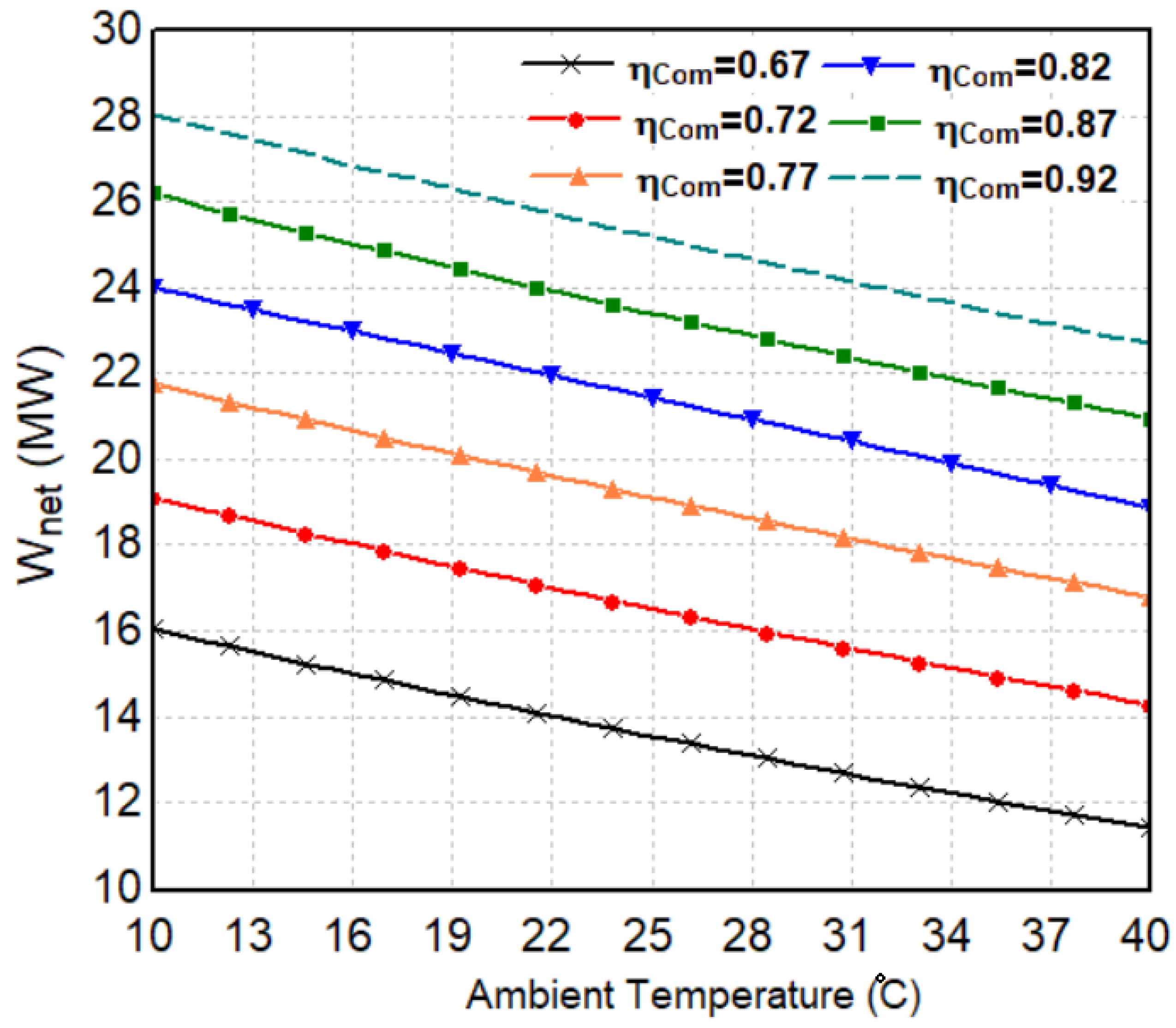
Considering all the points mentioned above, an ambient temperature increase reduced the net turbine power in both constant mass flow and constant volumetric flow. Figure 6 illustrates the changes in net output power in terms of ambient temperature variations in actual conditions for compressors with different efficiencies.
Figure 6 shows that for every 10-degree increase in ambient temperature, the net output power was reduced by 6 to 9.5%. The amounts 6% and 9.5% are related to the efficiencies of 0.98 and 0.67, respectively. For example, considering an efficiency of 0.82 for the compressor (the present case study), the net output power decreased by approximately 6.8% for every 10-degree increase in ambient temperature. It should be noted that the expressed percentages are not completely accurate and are presented only for rapid, acceptable estimation. Of course, the precise values can be determined from the diagrams (Figure 6).
In the next step, the proposed cycle was analyzed in the Bushehr city climate throughout the year to calculate the changes in net output power due to ambient temperature variations. The net output power amount was divided by the maximum annual net output power to demonstrate fluctuations in a dimensionless fashion. The simulation time started at noon on 1 January. The left axis in Figure 7 shows the fluctuations in ambient temperature throughout the year, which was a variable similar to hourly radiation intensity. The lowest ambient temperature during the year was 3.1 °C and the highest temperature was 44.8 °C. The maximum net output power obtained on the coldest day of the year was 25.5 MW, and the minimum net output power was 18.3 MW. This implies that as a consequence of the 41.7 °C increase in the ambient temperature, the net power decreased by 7.2 MW, which is equivalent to 28.3% of the maximum annual net power. After dividing this value by the range of the temperature variation (41.7 °C), it was concluded that net generated power decreases by 0.67% for every one-degree increase in ambient temperature.

4.1.4. Solar Fraction and Thermal Efficiency

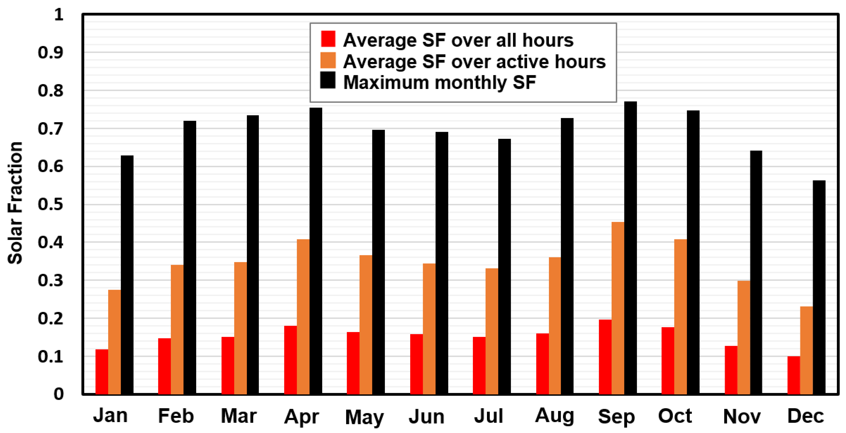
The solar system’s energy supply to total energy consumption is called the solar fraction (SF). The equation used to calculate the solar fraction has already been presented in the equations related to the heliostat in Table 1. In the following section, however, the changes in the solar fraction are compared based on different definitions. The red columns in Figure 8 show the average monthly solar fraction in different months (the main definition) because since the analyzed cycle lacked an energy storage system, the solar system was deactivated in the absence of the sun, causing average daily solar fraction decreases. The orange columns show the average monthly solar fraction at the hours of the presence of irradiance. Comparing the red and orange columns demonstrates that a heat recovery system can increase the solar fraction even more than two times. The black columns also indicate the maximum solar fraction recorded during each month. As can be observed, in some cases, the proposed solar system could provide up to 77% of the total energy required for the cycle under Bushehr climate conditions.
Figure 9 shows the changes in the solar fraction (equivalent to the red column) during four considered days. As was also predictable, parameter SF increased dramatically during the middle hours of the day and tended to be zero before and after.
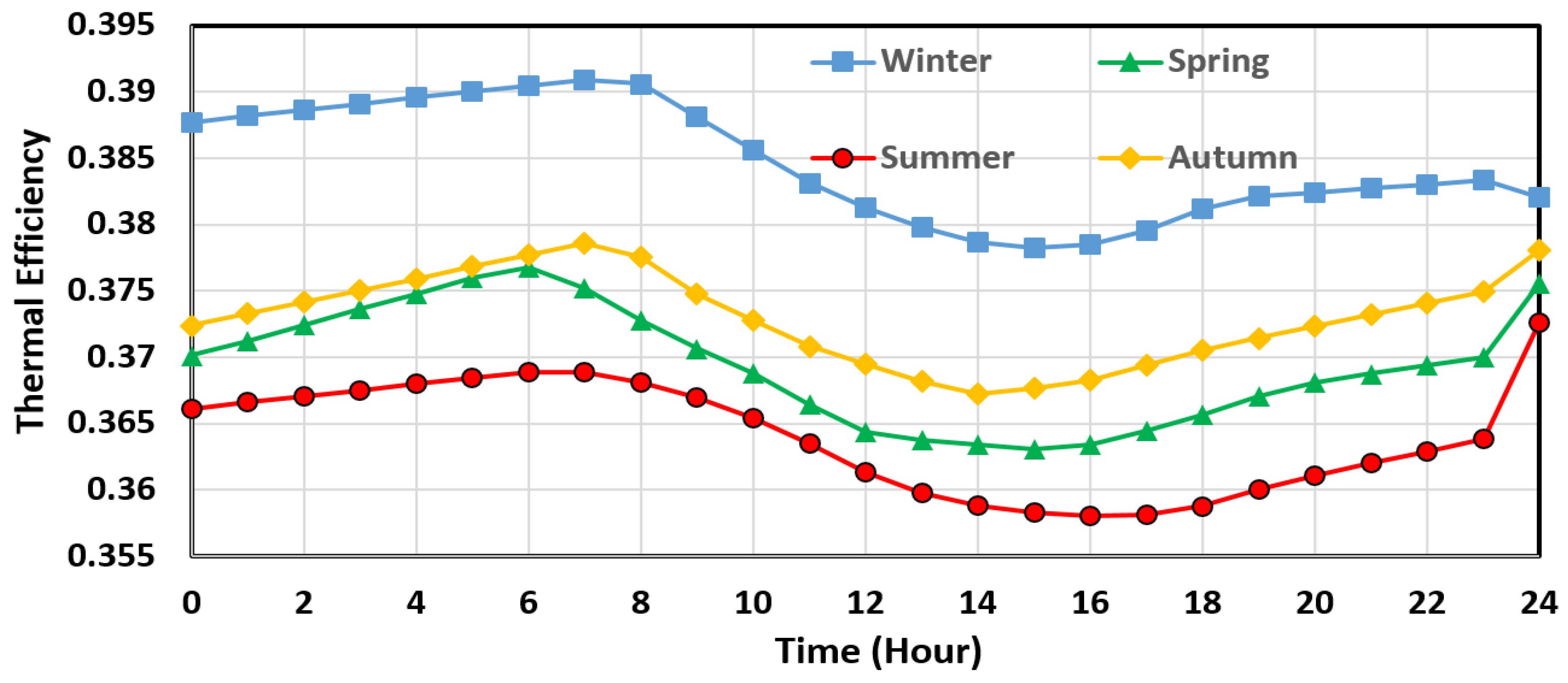
Figure 10 shows the efficiency changes at different hours of the day, and the results show that the efficiency of the gas power cycle is inversely related to the ambient temperature. The efficiency was reduced from late at night until before sunrise when the ambient temperature dropped. Then, with the sun rising and the air warming until the middle of the day, a decrease in efficiency was observed that was similar to the changes in net output power during the day.
The above results imply that the cogeneration system had the highest performance in winter and the lowest performance in summer. Additionally, in the middle of the day, there was a relative reduction in the system’s thermal efficiency in all four seasons. In the coldest hour of the year, when the temperature dropped to 3.15, the thermal efficiency went up to 39.11%. In contrast, when the temperature reached 44.8 °C in the hottest hour of the year, the thermal efficiency dropped to 35.26°. Given that the annual average efficiency was 0.372, according to Equation (18), the heat rate (HR) will be equal to 9670.

4.1.5. Fresh Water Production

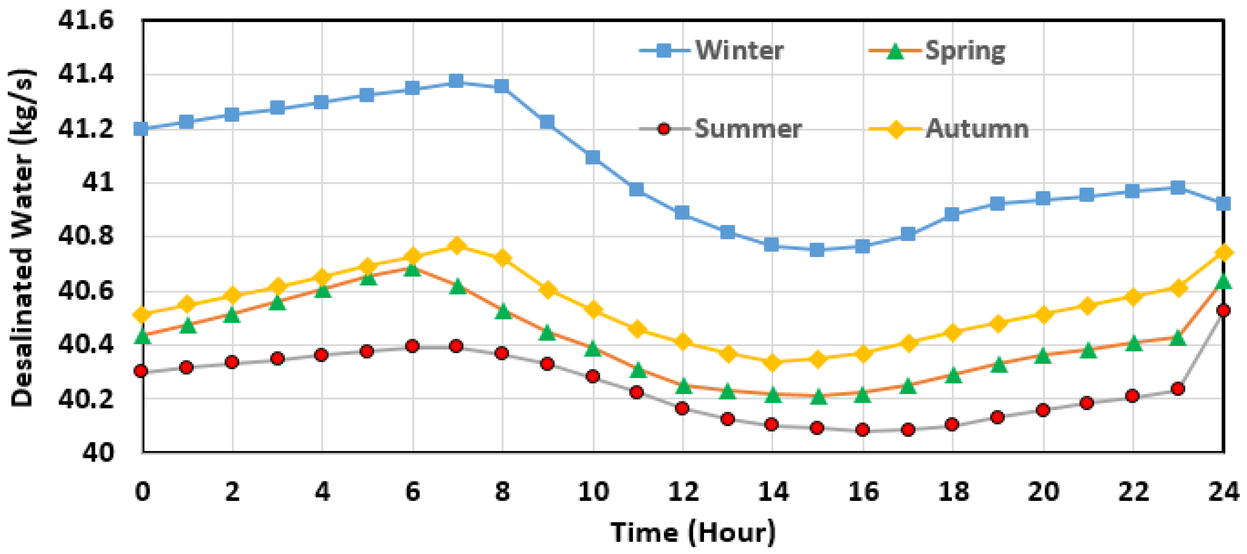
Although the turbine outlet temperature increased with the ambient temperature, the outlet mass flow rate of the turbine decreased. From a heat transfer point of view, the effect of the mass flow reduction in this process overcame the impact of the turbine outlet temperature increase. As a result, less energy was transferred to the motive fluid in the heat exchanger, consequently decreasing the mass flow rate of the produced freshwater.
Figure 11 illustrates the fluctuations in the mass flow rate of the freshwater produced on four different days of the year. The nominal performance coefficient of the desalination unit was calculated to be 4.1.
Finally, the results showed that freshwater production’s maximum annual mass flow rate was 41.4 kg/s, the annual minimum was 40 kg/s, and the annual average was 40.5 kg/s. As a result, the proposed system could produce approximately 1.2 million cubic meters of freshwater per year under Bushehr climate conditions. In the calculations, the temperature of the water entering the desalination unit was assumed to be 20% lower than the ambient temperature. Therefore, if the inlet water temperature was assumed to be equal to the ambient temperature, the fluctuations in the mass flow rate of the produced water would be slightly lower than those of the current state. Additionally, if the temperature of the water entering the desalination unit was considered equal to a constant number such as 20 °C, the fluctuations in the mass flow rate of the produced water would increase by approximately 2.5 times more than those of the current state. In this case, the produced fresh water’s minimum and maximum mass flow rates would be 39 kg/s and 42.5 kg/s, respectively. Nevertheless, considering the temperature of inlet water as a variable parameter seemed more rational.

4.2. Exergy Analysis

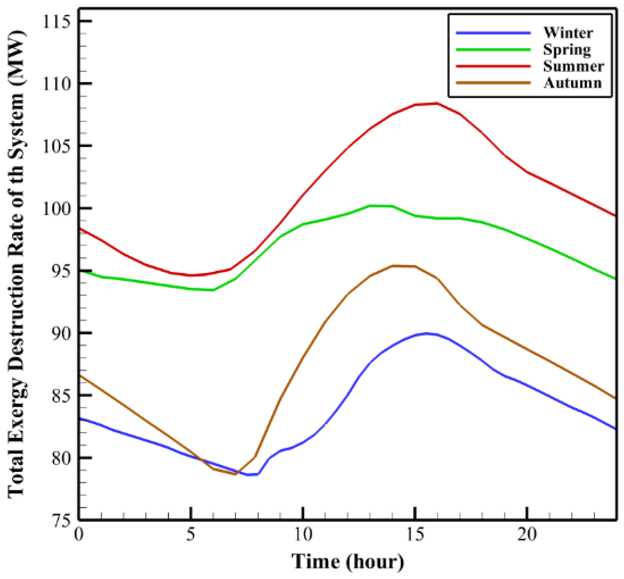
Figure 12 illustrates the exergy destruction rate of the entire system during four days in different seasons. The total exergy destruction rate of the system had the highest value in summer and the lowest value in winter. Additionally, during the day, the rate of total exergy destruction significantly increased in the middle of the day. As a result, it can be concluded that the higher the ambient temperature is, the greater the total exergy destruction rate will be.
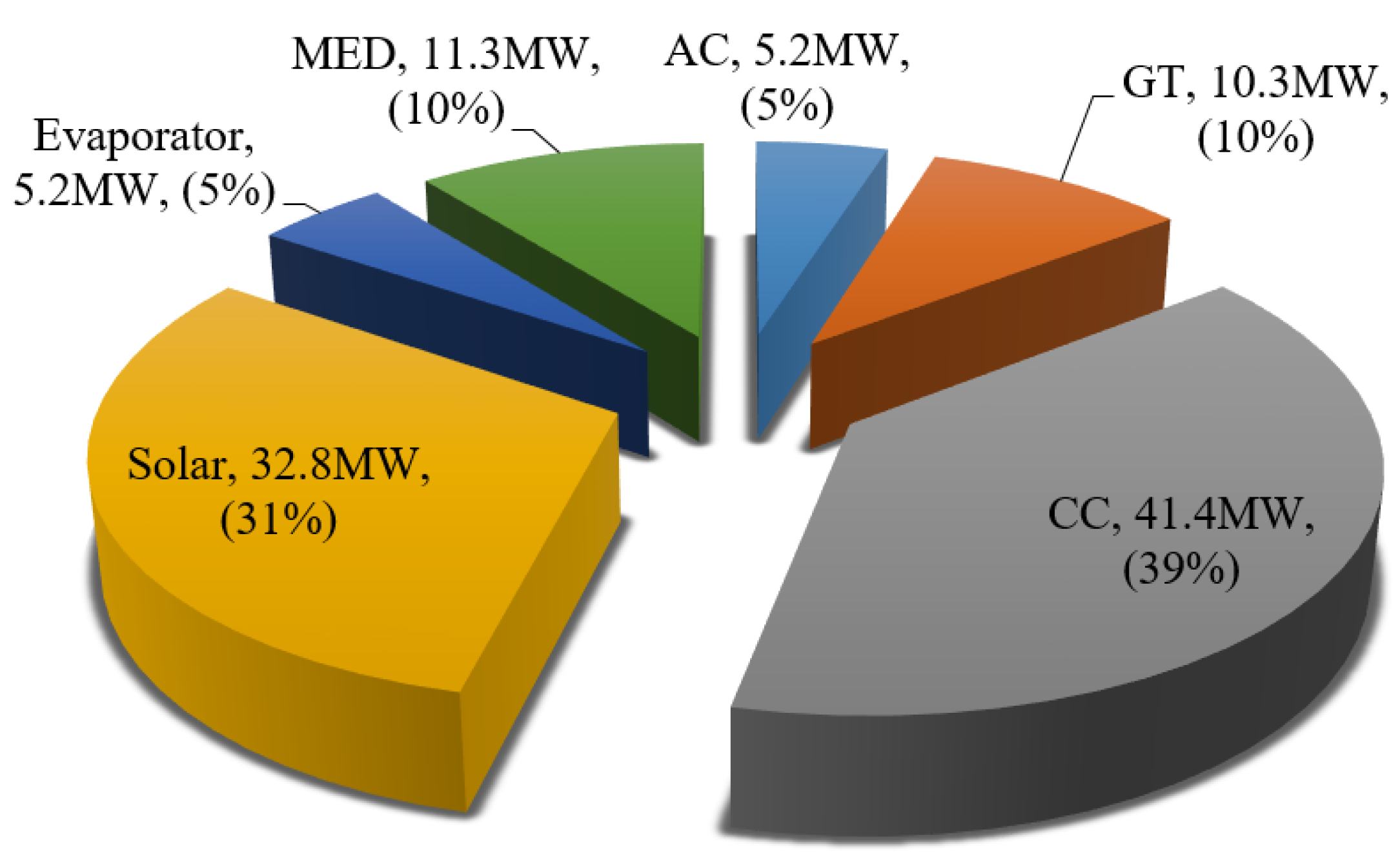
Nevertheless, it seems necessary to determine the contribution of the different components to total exergy destruction. Figure 13 shows a pie diagram of the exergy destruction distribution of each element in the middle of a summer day. The results presented in Figure 13 show that the exergy destruction rate of the solar system (32.8 MW) contributed approximately 31% of the total exergy destruction and the combustion chamber (CC) had the highest contribution to the total exergy destruction of the system (approximately 39%).
In contrast, the compressor and evaporator had the most minor contributions to the total exergy destruction rate, with approximately 5% (5.2 MW). Overall, it was concluded that the solar system and the components involved in power generation account for the highest portion of total exergy destruction. Therefore, the total exergy destruction rate can be reduced most effectively by focusing on these components and improving their performance.

4.3. Economic Analysis

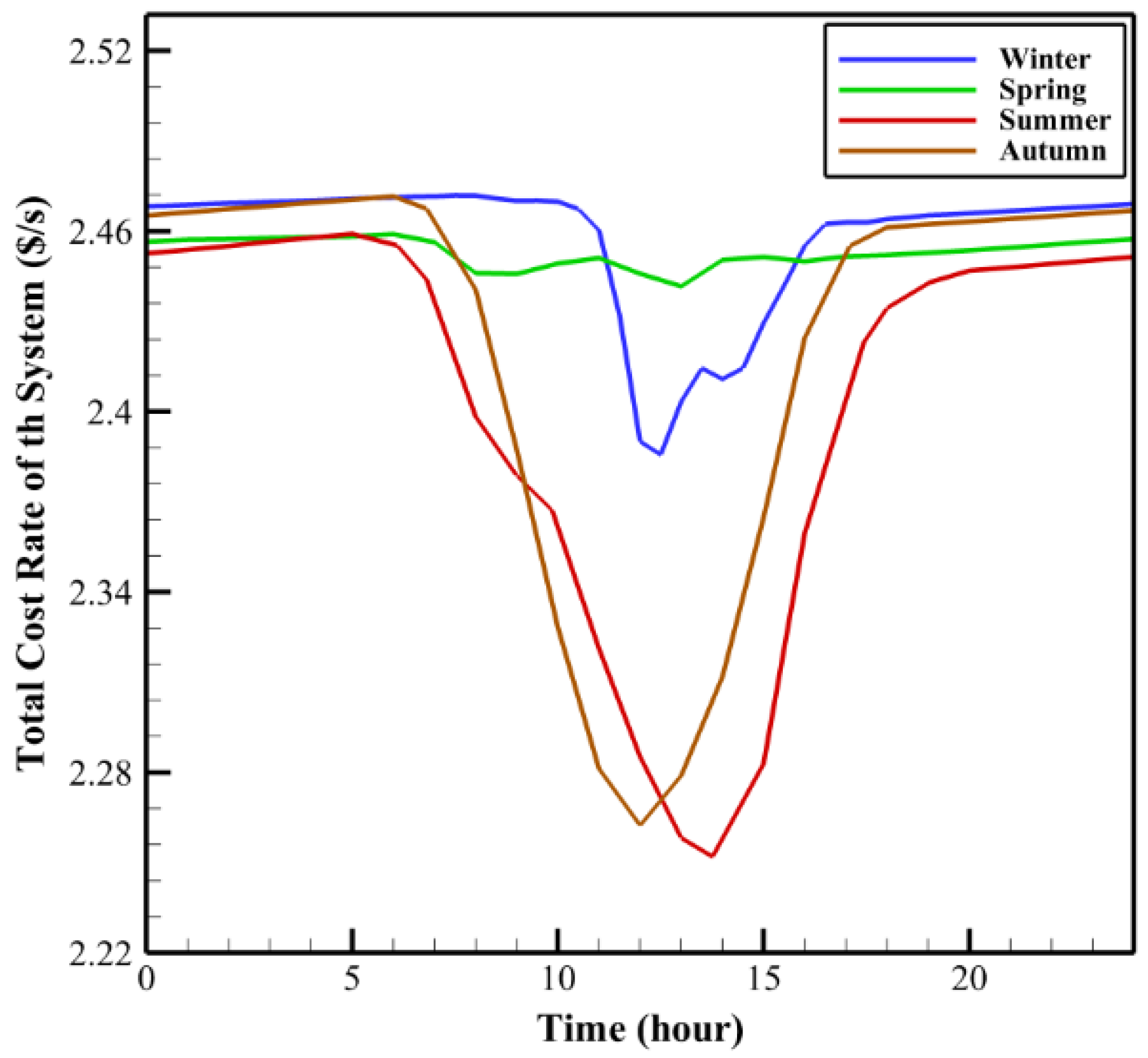
Figure 14 shows changes in the rate of the total system cost during four days in different seasons of the year. The system cost rate had the lowest value in summer and the highest value in winter. Additionally, during one day, getting closer to the middle of the day, the system cost rate dramatically decreased. Due to fuel consumption decreasing in the middle of the day, the system cost rate experienced a descending trend.
During sunny hours, the fuel consumption decrease led to reduced consumption costs. By calculating the fuel consumption reduction in each month and placing it in Equation (21), the cost saved on fuel consumption due to the use of the solar system could be computed. Figure 15 shows the cost savings on fuel consumption each month. For example, approximately USD 248,400 was saved in the fourth month on fuel consumption. The total cost reduction in fuel consumption exceeded USD 2.4 million per year, which is a very considerable amount. These results will be more useful when reported in a unit-per-power manner. For example, dividing the amount of the saved cost by the net output power will allow the obtained results to be compared with similar results of other studies.
Figure 7 shows that the net output power varied at different hours of each day. However, by dividing the annual saved cost by the average net-generated power, which was assumed to be 25 MW, it was concluded that using such a solar system makes it possible to save costs by approximately USD 96,000 (USD/MW·year). For instance, the saved cost amount in a gas power plant with a 25-MW turbine will be approximately USD 2.4 million per year.
It must be noted that these values were calculated based on global fossil fuel prices, which are much higher than the prices of electricity and fuel in Iran. For example, Iran’s electricity and natural gas cost 3 cents/kWh and 2.6 cents/m3, respectively, whereas, the corresponding values in countries such as the United Kingdom are equal to 20 cents/kWh and 18 cents/m3, respectively [34].

4.4. Environmental Analysis

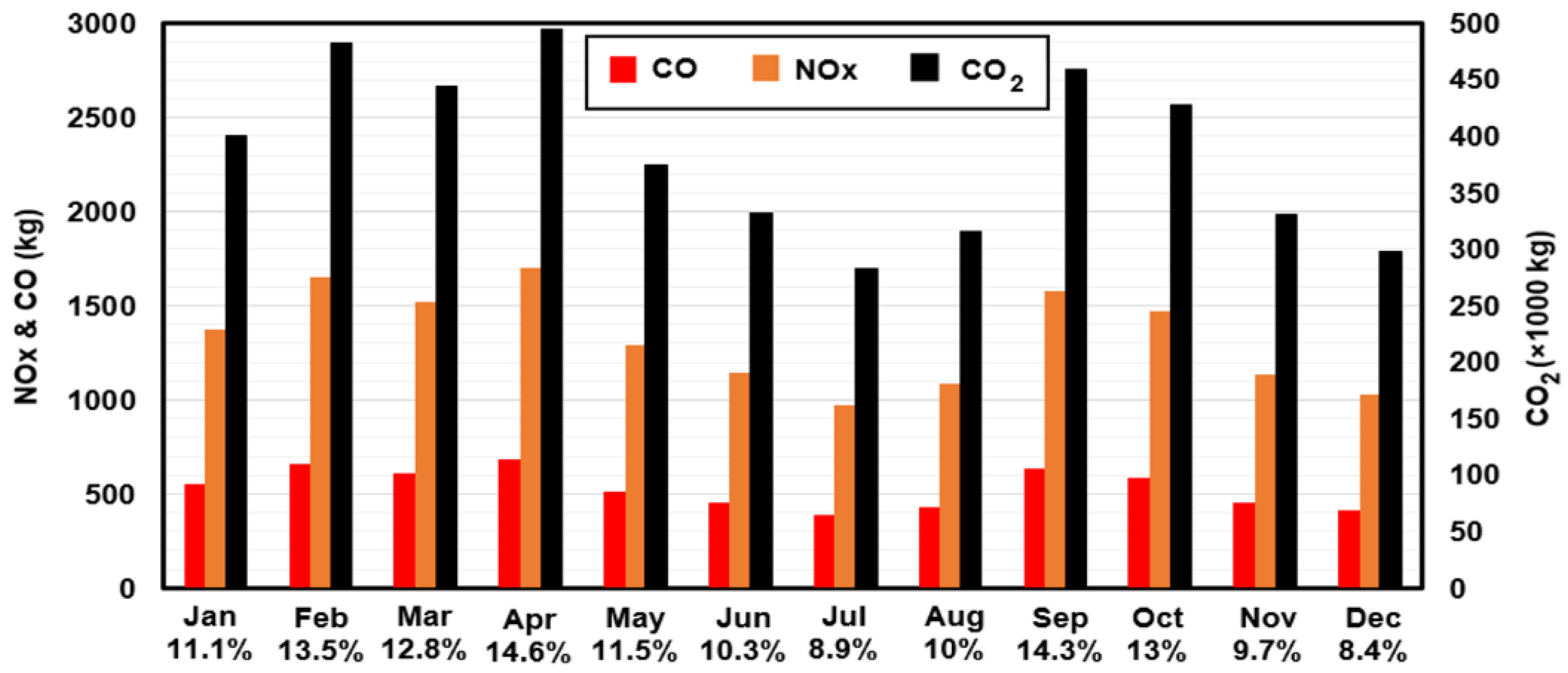
Pollutant emissions were calculated in terms of fuel consumption and according to Equations (22)–(27). Therefore, the amounts of pollutant emissions were proportional to those of fuel consumption. Table 4 shows the base cycle’s monthly fuel consumption and CO, CO2, and NOx emissions, which lacked a solar preheating system. The amounts of emissions reduction, which were achieved by using the solar preheating system, are presented in Figure 16. The left axis of this figure shows the monthly decrease in emissions such as carbon monoxide and NOx. Similarly, the right axis shows the monthly reduction in CO2.
The horizontal axis shows the reduction percentage of pollutant emissions in the proposed cycle compared to the base cycle.
According to Table 4, the mass flow rate of fuel consumed in summer is lower than that in other seasons; this is because increasing the ambient temperature reduces the mass flow rate of the air entering the combustion chamber. Additionally, due to the increase in solar radiation intensity during warm seasons, fossil fuel consumption significantly decreases, and the solar system supplies most of the required energy.
Since emission values are calculated based on fuel consumption, the percentage written below the name of each month in Figure 16 indicates both the fuel consumption reduction and the emissions reduction. For example, by using the proposed solar preheater, fuel consumption and emissions of CO, CO2, and NOx decreased by 10.3% in June. Of course, the annual emission reductions of CO, NOx, and CO2 were equal to 6379, 15,949, and 4,643,050 kg, respectively. The highest reduction in fuel consumption and emissions occurred in September and was equal to 14.3%.

4.5. Results of Repeated Calculations for Different Cities

One of the valuable comparisons that can be made for solar systems is comparing the performance of the proposed cycle under the climate conditions of cities in which either one solar power plant has already been implemented or there is the potential to implement a solar–hybrid power plant. Hence, in the present section, the performance of the proposed system is evaluated under the climate conditions of some cities in Iran and some other cities where concentrating solar power (CSP) systems have already been built.
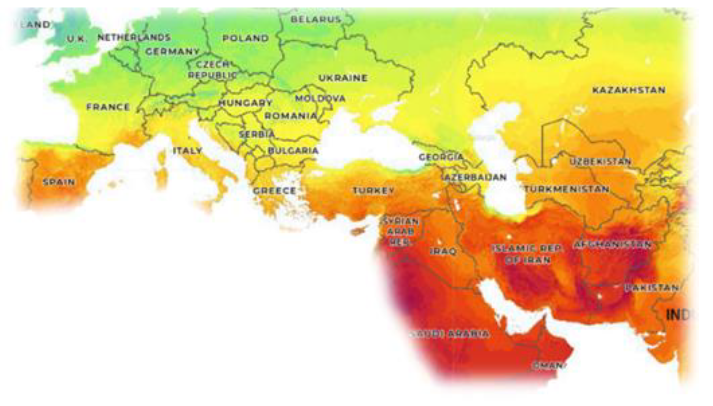
Preliminary studies showed Iran is in a favorable geographical position regarding receiving solar radiation. For example, as shown in Figure 17, Spain, one of the leading countries in the development of solar power tower plants that has a great number of solar power plants, receives less annual solar radiation than Iran. Thus, Iran has plenty of potential to build solar and hybrid power plants.
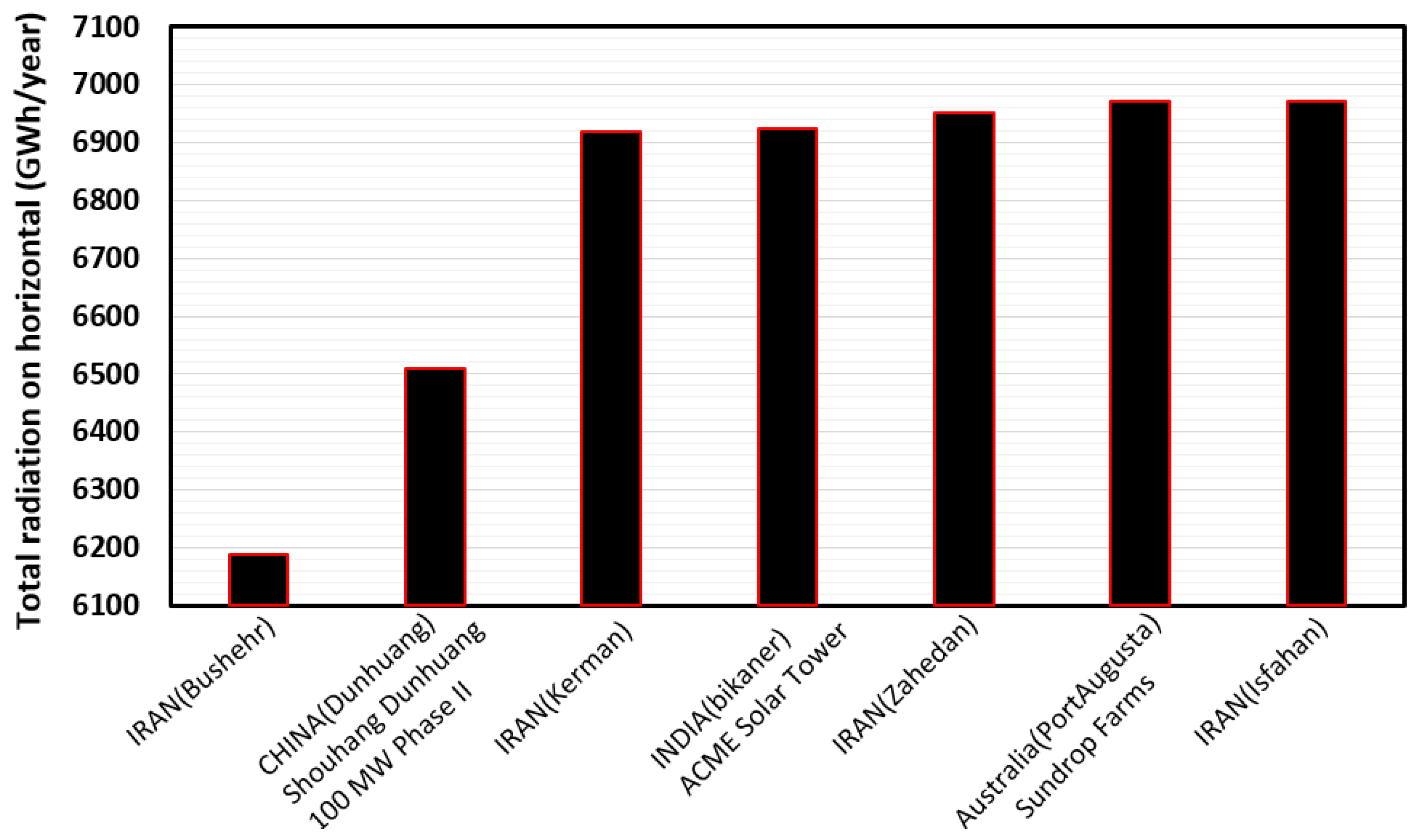
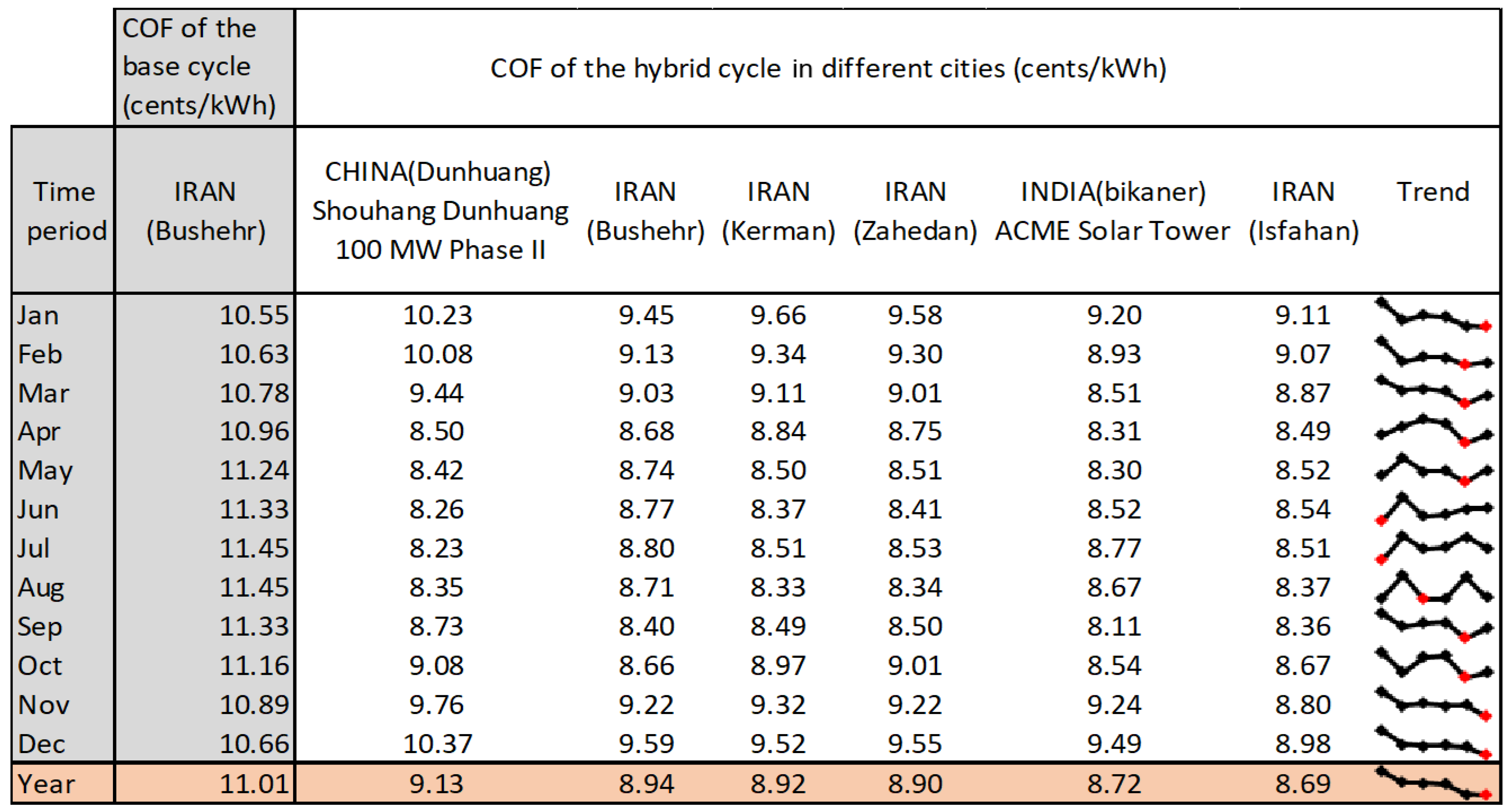
The results presented in the previous sections were obtained based on Bushehr weather conditions. The proposed cycle was also evaluated under the climate conditions of cities such as Isfahan, Zahedan, and Kerman in Iran and other cities such as Port Augusta in Australia, Bikaner in India, and Dunhuang in China, which have solar power plants. The names of these power plants and the solar energy received in each of these areas are shown in Figure 18. As shown in Figure 18, many regions in Iran receive significant solar energy. At the same time, despite less solar energy reception, some regions worldwide have already built solar power tower plants. In order to evaluate the performance of the proposed system in different regions, the cost of one kilowatt-hour of electricity generation was calculated in each of these regions (Figure 19). Climate information for each region was also obtained using Meteonorm software(Ver: 7.3.3), one of the best ways today to access the most up-to-date weather information in different locations in the world.
In Figure 19, the first column on the left shows the period; the second column shows the cost of generating electricity for the base cycle (the proposed cycle without the solar system) in Bushehr. The next six columns show the cost of generating electricity using the proposed cycle in six different regions of the world. The bottom row of the table shows the yearly average cost of electricity generation. As can be observed, the cost of generating electricity without using the solar system in Bushehr is approximately 11 Cents/kWh, while with the solar system, this cost decreases by 18.8% and reaches 8.94 Cents/kWh.
In the last column, six-point charts are presented that compare the cost of electricity generation among six different cities and identify the lowest cost by a red symbol. For example, the cost of electricity generation with the solar system in the second to fifth months in the Indian city of Bikaner is lower than that in other cities. However, overall, the lowest cost of electricity generation during the year belongs to Isfahan, in which the cost of electricity generation is reduced by more than 20% compared to the base cycle.
Another point inferred from Figure 19 is the changes in the cost of electricity generation in summer and winter. In the base cycle, the cost of electricity generation in warm seasons is higher than in other seasons. This is because, in hot seasons, an increase in the ambient temperature leads to a decrease in both net output power and thermal efficiency. Given Equation (18), the HR value increases. According to Equations (20) and (21), the cost of electricity generation will increase as well. However, in contrast, with the proposed system, the cost of electricity generation in summer is lower than that in winter due to the use of the solar preheater. Of course, this result is correct, provided that the fuel price is constant throughout the year.
These observations clearly demonstrate the importance of integrating such power plants with solar systems mainly because fuel consumption reduction reduces not only the cost of power generation but also environmental pollution.
5. Conclusions

In the current study, energy, exergy, exergoeconomics, and environmental analyses were performed for a solar–hybrid cogeneration cycle equipped with a heliostat. All analyses were performed dynamically with a one-hour time step throughout the year. The studies were conducted with both assumptions of constant mass flow rate and of constant volumetric flow rate. A sensitivity analysis was performed regarding ambient temperature and, finally, the proposed cycle performance was evaluated and compared in six different cities. The general results of the study are as follows:
  • The results of the annual performance analysis for Bushehr’s climate conditions showed that the range of the net output power achieved on the warmest and coldest day was between 18.3 MW and 25.5 MW. After dividing the power variation amplitude by the range of the temperature variations, it was concluded that the net generated power decreased by 0.67% for every one-degree increase in ambient temperature. Furthermore, the obtained results demonstrated that for every 10-degree increase in ambient temperature, the net output power experienced a reduction between 6% and 9.5%. The exact value of the reduction depended on the efficiency.
  • The highest and lowest performances of the proposed cogeneration system, which occurred on the coldest and warmest days, were 0.39 and 0.35, respectively. The HR corresponding to the average annual cycle efficiency was 9670.
  • The maximum mass flow rate of freshwater production was 41.4 kg/s, the minimum rate was 40 kg/s, and the average rate was 40.5 kg/s. As a result, this cycle could produce approximately 1.2 million cubic meters of freshwater per year in Bushehr.
  • The results of the exergy analysis showed that the rate of exergy destruction increased with increasing temperature. The combustion chamber and the solar system, with approximately 39% and 31% of the total exergy destruction, had the most significant contribution to the total exergy destruction.
  • The results of the economic analysis showed that using a system similar to the proposed one leads to a saving of approximately USD 96,000 (USD/MW.year) on fuel consumption, which would be USD 2.4 million per year for the turbine in question with a nominal net power of 25 MW. Furthermore, the cost of generating electricity without using the solar system in Bushehr is approximately 11 Cents/kWh, which can be reduced by 18.8% by using the solar system. Additionally, among the six considered cities, Isfahan had the lowest annual cost of electricity generation (8.69 Cents/kWh).
  • The environmental analysis results showed that the annual emissions reduction of CO, NOx, and CO2 were 6379, 15,949, and 4,643,050 kg/year, respectively. The largest decrease in fuel consumption and monthly emissions occurred in September and was equal to 14.3%.
The weather data utilized in the present investigation pertained to the year 2016. Additionally, the outcomes were deemed valid solely in accordance with the underlying assumptions and cycle characteristics presented. The cost of fossil fuels in this study was determined based on prevailing prices in Iran.
In future studies, it is suggested that parameters such as the number and arrangement of the mirrors are optimized to design the solar system more efficiently.

Author Contributions

Conceptualization, M.A.J. and M.A.; Methodology, M.A.J.; Software, H.D. and M.A.; Writing—original draft, H.D. and M.A.J.; Supervision, R.G. All authors have read and agreed to the published version of the manuscript.

Funding

This research received no external funding.

Data Availability Statement

The data is unavailable due to privacy.

Conflicts of Interest

The authors declare no conflict of interest.

Nomenclature

LatinGreekSubscriptsAbbreviation
Q: Heat transfer rate (kW)φ: density (kg m−3)B: brineMED: Multi Effect Desalination
t: Time (h)δ: Differenced: distillateTVC: Thermal Vapor Compressor
m: Mass flow rate (kg/s)ղ: Efficiency (%)f: feedDSG: Direct Steam Generation
E: Exergy (kW) L: liquidDE: Double Effect
W: Work (kW) v: vaporPR: Performance Ratio
Cp: Specific heat (kJ/kg·°C) t: Tube
A: Area (m2) s: steam
Ċ: Cost rate ($/h) sat: Saturation
c: Unit cost ($/kJ) cw: Cooling water
D: Distillate mass flow rate (kg/s) i: Effect number
Ė: Exergy rate (kW) n: Last effect
ER: Entrainment ratio o: out
f: Exergoeconomic factor sw: seawater
GOR: Gain Output Ration E: Evaporator/effect
h: Specific enthalpy (kJ/kg) SH: superheat
ṁ: Mass flow rate (kg/s)
P: Pressure (bar)
Q ˙ : Heat flux (kW)
R: Gas constant (J·mol−1·K−1)
r: Relative cost difference
s: Entropy (kJ/kg·°C)
T: Temperature (K)
X: Salt weight percentage
x: Mass fraction (%)
Z: Purchase cost ($)
Ż: Total cost rate ($/h)

References

  1. Burek, P.; Satoh, Y.; Fischer, G.; Kahil, M.T.; Scherzer, A.; Tramberend, S.; Nava, L.F.; Wada, Y.; Eisner, S.; Flörke, M.; et al. Water Futures and Solution-Fast Track Initiative; IIASA: Laxenburg, Austria, 2016. [Google Scholar]
  2. Alirahmi, S.M.; Dabbagh, S.R.; Ahmadi, P.; Wongwises, S. Multi-objective design optimization of a multi-generation energy system based on geothermal and solar energy. Energy Convers. Manag. 2020, 205, 112426. [Google Scholar] [CrossRef]
  3. You, H.; Han, J.; Liu, Y. Conventional and advanced exergoeconomic assessments of a CCHP and MED system based on solid oxide fuel cell and micro gas turbine. Int. J. Hydrogen Energy 2020, 45, 12143–12160. [Google Scholar] [CrossRef]
  4. You, H.; Han, J.; Liu, Y.; Chen, C.; Ge, Y. 4E analysis and multi-objective optimization of a micro poly-generation system based on SOFC/MGT/MED and organic steam ejector refrigerator. Energy 2020, 206, 118122. [Google Scholar] [CrossRef]
  5. Ahmadi, P.; Fakhari, I.; Rosen, M.A. A comprehensive approach for tri-objective optimization of a novel advanced energy system with gas turbine prime mover, ejector cooling system and multi-effect desalination. Energy 2022, 254, 124352. [Google Scholar] [CrossRef]
  6. Shakib, S.E.; Amidpour, M.; Boghrati, M.; Ghafurian, M.M.; Esmaieli, A. New approaches to low production cost and low emissions through hybrid MED-TVC+ RO desalination system coupled to a gas turbine cycle. J. Clean. Prod. 2021, 295, 126402. [Google Scholar] [CrossRef]
  7. Khouya, A. 4E assessment of a hybrid RO/MED-TVC desalination plant powered by CPV/T systems. Energy Convers. Manag. 2023, 277, 116666. [Google Scholar] [CrossRef]
  8. Cipollina, A.; Agnello, M.; Piacentino, A.; Tamburini, A.; Ortega, B.; Palenzuela, P.; Alarcon, D.; Micale, G. A dynamic model for MED-TVC transient operation. Desalination 2017, 413, 234–257. [Google Scholar] [CrossRef]
  9. Elsayed, M.L.; Mesalhy, O.; Mohammed, R.H.; Chow, L.C. Effect of disturbances on MED-TVC plant characteristics: Dynamic modeling and simulation. Desalination 2018, 443, 99–109. [Google Scholar] [CrossRef]
  10. Hafdhi, F.; Khir, T.; Ben Yahia, A.; Ben Brahim, A. Exergoeconomic optimization of a double effect desalination unit used in an industrial steam power plant. Desalination 2018, 438, 63–82. [Google Scholar] [CrossRef]
  11. Elsayed, M.L.; Mesalhy, O.; Mohammed, R.H.; Chow, L.C. Exergy and thermo-economic analysis for MED-TVC desalination systems. Desalination 2018, 447, 29–42. [Google Scholar] [CrossRef]
  12. Elsayed, M.L.; Mesalhy, O.; Mohammed, R.H.; Chow, L.C. Transient performance of MED processes with different feed configurations. Desalination 2018, 438, 37–53. [Google Scholar] [CrossRef]
  13. You, H.; Han, J.; Liu, Y. Performance assessment of a CCHP and multi-effect desalination system based on GT/ORC with inlet air precooling. Energy 2019, 185, 286–298. [Google Scholar] [CrossRef]
  14. Kianfard, H.; Khalilarya, S.; Jafarmadar, S. Exergy and exergoeconomic evaluation of hydrogen and distilled water production via combination of PEM electrolyzer, RO desalination unit and geothermal driven dual fluid ORC. Energy Convers. Manag. 2018, 177, 339–349. [Google Scholar] [CrossRef]
  15. Javadi, M.A.; Khalaji, M.; Ghasemiasl, R. Exergoeconomic and environmental analysis of a combined power and water desalination plant with parabolic solar collector. Desalination Water Treat. 2020, 193, 212–223. [Google Scholar] [CrossRef]
  16. Safari, F.; Dincer, I. Development and analysis of a novel biomass-based integrated system for multigeneration with hydrogen production. Int. J. Hydrogen Energy 2019, 44, 3511–3526. [Google Scholar] [CrossRef]
  17. Dong, Z.; Liu, M.; Huang, X.; Zhang, Y.; Zhang, Z.; Dong, Y. Dynamical modeling and simulation analysis of a nuclear desalination plant based on the MED-TVC process. Desalination 2019, 456, 121–135. [Google Scholar] [CrossRef]
  18. Wang, R.; Sun, J.; Hong, H.; Jin, H. Comprehensive evaluation for different modes of solar-aided coal-fired power generation system under common framework regarding both coal-savability and efficiency-promotability. Energy 2018, 143, 151–167. [Google Scholar] [CrossRef]
  19. Guo, S.; Liu, Q.; Sun, J.; Jin, H. A review on the utilization of hybrid renewable energy. Renew. Sustain. Energy Rev. 2018, 91, 1121–1147. [Google Scholar] [CrossRef]
  20. Ahmad, A.D.; Abubaker, A.M.; Najjar, Y.S.; Manaserh, Y.M.A. Power boosting of a combined cycle power plant in Jordan: An integration of hybrid inlet cooling & solar systems. Energy Convers. Manag. 2020, 214, 112894. [Google Scholar]
  21. Javadi, M.; Najafi, N.J.; Abhari, M.K.; Jabery, R.; Pourtaba, H. 4E analysis of three different configurations of a combined cycle power plant integrated with a solar power tower system. Sustain. Energy Technol. Assess. 2021, 48, 101599. [Google Scholar] [CrossRef]
  22. Mohammadi, K.; McGowan, J.G.; Saghafifar, M. Thermoeconomic analysis of multi-stage recuperative Brayton power cycles: Part I-hybridization with a solar power tower system. Energy Convers. Manag. 2019, 185, 898–919. [Google Scholar] [CrossRef]
  23. Alirahmi, S.M.; Khoshnevisan, A.; Shirazi, P.; Ahmadi, P.; Kari, D. Soft computing based optimization of a novel solar heliostat integrated energy system using artificial neural networks. Sustain. Energy Technol. Assess. 2022, 50, 101850. [Google Scholar] [CrossRef]
  24. Behzadi, A.; Gholamian, E.; Alirahmi, S.M.; Nourozi, B.; Sadrizadeh, S. A comparative evaluation of alternative optimization strategies for a novel heliostat-driven hydrogen production/injection system coupled with a vanadium chlorine cycle. Energy Convers. Manag. 2022, 267, 115878. [Google Scholar] [CrossRef]
  25. Giostri, A.; Binotti, M.; Sterpos, C.; Lozza, G. Small scale solar tower coupled with micro gas turbine. Renew. Energy 2020, 147, 570–583. [Google Scholar] [CrossRef]
  26. Kerme, E.D.; Orfi, J.; Fung, A.S.; Salilih, E.M.; Khan, S.U.-D.; Alshehri, H.; Ali, E.; Alrasheed, M. Energetic and exergetic performance analysis of a solar driven power, desalination and cooling poly-generation system. Energy 2020, 196, 117150. [Google Scholar] [CrossRef]
  27. Dhivagar, R.; Shoeibi, S.; Kargarsharifabad, H.; Ahmadi, M.H.; Sharifpur, M. Performance enhancement of a solar still using magnetic powder as an energy storage medium-exergy and environmental analysis. Energy Sci. Eng. 2022, 10, 3154–3166. [Google Scholar] [CrossRef]
  28. Sultan, S.M.; Tso, C.P.; Ervina Efzan, M.N. A case study on effect of inclination angle on performance of photovoltaic solar thermal collector in forced fluid mode. Renew. Energy Res. Appl. 2020, 1, 187–196. [Google Scholar]
  29. Beiranvand, A.; Ehyaei, M.A.; Ahmadi, A.; Silvaria, J.L. Energy, exergy, and economic analyses and optimization of solar organic Rankine cycle with multi-objective particle swarm algorithm. Renew. Energy Res. Appl. 2021, 2, 9–23. [Google Scholar]
  30. Kaviri, A.G.; Jaafar, M.N.M.; Lazim, T.M. Modeling and multi-objective exergy based optimization of a combined cycle power plant using a genetic algorithm. Energy Convers. Manag. 2012, 58, 94–103. [Google Scholar] [CrossRef]
  31. Syahrul, S.; Hamdullahpur, F.; Dincer, I. Exergy analysis of fluidized bed drying of moist particles. Exergy Int. J. 2002, 2, 87–98. [Google Scholar] [CrossRef]
  32. Ogorure, O.J.; Oko, C.O.C.; Diemuodeke, E.O.; Owebor, K. Energy, exergy, environmental and economic analysis of an agricultural waste-to-energy integrated multigeneration thermal power plant. Energy Convers. Manag. 2018, 171, 222–240. [Google Scholar] [CrossRef]
  33. Sharma, P.; Bhatti, T. A review on electrochemical double-layer capacitors. Energy Convers. Manag. 2010, 51, 2901–2912. [Google Scholar] [CrossRef]
  34. Ahmadi, P.; Dincer, I.; Rosen, M.A. Exergy, exergoeconomic and environmental analyses and evolutionary algorithm based multi-objective optimization of combined cycle power plants. Energy 2011, 36, 5886–5898. [Google Scholar] [CrossRef]
  35. Anvari, S.; Mahian, O.; Taghavifar, H.; Wongwises, S.; Desideri, U. 4E analysis of a modified multigeneration system designed for power, heating/cooling, and water desalination. Appl. Energy 2020, 270, 115107. [Google Scholar] [CrossRef]
  36. Dincer, I.; Rosen, M.A.; Ahmadi, P. Optimization of Energy Systems; John Wiley & Sons: Hoboken, NJ, USA, 2017. [Google Scholar]
  37. Molamohamadi, Z.; Talaei, M.R. Analysis of a proper strategy for solar energy deployment in Iran using SWOT matrix. Renew. Energy Res. Appl. 2022, 3, 71–78. [Google Scholar]
  38. Alayi, R.; Jahanbin, F. Generation management analysis of a stand-alone photovoltaic system with battery. Renew. Energy Res. Appl. 2020, 1, 205–209. [Google Scholar]
  39. Khoshgoftar Manesh, M.H.; Abdolmaleki, M.; Vazini Modabber, H.; Rosen, M.A. Dynamic advanced exergetic, exergoeconomic, and environmental analyses of a hybrid solar city gate station. J. Energy Resour. Technol. 2021, 143, 102105. [Google Scholar] [CrossRef]
  40. Ahmadi, M.H.; Ghazvini, M.; Sadeghzadeh, M.; Alhuyi Nazari, M.; Kumar, R.; Naeimi, A.; Ming, T. Solar power technology for electricity generation: A critical review. Energy Sci. Eng. 2018, 6, 340–361. [Google Scholar] [CrossRef]
  41. Mohamad, H.A.E.; Medhat, E.M.E.; Mohamed, R.; Muthu, M. Use of Solar Chimney in renewable energy applications–A review. Renew. Energy Res. Appl. 2021, 2, 117–128. [Google Scholar]
Figure 1. The schematic of the suggested cycle (MED system with heliostat).
Sustainability 15 08792 g001
Figure 2. Power consumption variations assuming constant mass flow rate with (a) a pressure ratio of 19.4 and (b) different pressure ratios.
Sustainability 15 08792 g002
Figure 3. The effect of changes in ambient temperature on the density of air entering the compressor.
Sustainability 15 08792 g003
Figure 4. The effect of ambient temperature variations on compressor consumption with constant/variable pressure ratios and constant volumetric flow rate.
Sustainability 15 08792 g004
Figure 5. Schematic of how the compressor and turbine power changed due to increased ambient temperature.
Sustainability 15 08792 g005
Figure 6. Changes in net output power in terms of ambient temperature variations with constant volumetric flow rate and variable PR.
Sustainability 15 08792 g006
Figure 7. Comparison of changes in ambient temperature versus relative net-generated power.
Sustainability 15 08792 g007
Figure 8. Comparison of monthly and maximum SF with solar fractions calculated during hours of presence irradiance.
Sustainability 15 08792 g008
Figure 9. The graph shows changes in SF during 24 h periods in four seasons.
Sustainability 15 08792 g009
Figure 10. Diagram of changes in thermal efficiency during 24 h periods in four seasons.
Sustainability 15 08792 g010
Figure 11. Variations in the mass flow rate of freshwater produced during 24 h periods in different seasons of the year.
Sustainability 15 08792 g011
Figure 12. Changes in the total exergy destruction rate during 24 h periods in different seasons of the year.
Sustainability 15 08792 g012
Figure 13. Pie diagram of the exergy destruction distribution in each component of the system.
Sustainability 15 08792 g013
Figure 14. Graph of changes in the cost rate of the system during four days in different seasons of the year.
Sustainability 15 08792 g014
Figure 15. Cost saving on fuel consumption in different months.
Sustainability 15 08792 g015
Figure 16. Amounts of fuel consumption reduction in other months.
Sustainability 15 08792 g016
Figure 17. Solar irradiance intensity distribution in different countries.
Sustainability 15 08792 g017
Figure 18. Comparison of annual radiation received in some cities of Iran and other cities in China, Australia, and India that have solar tower power plants.
Sustainability 15 08792 g018
Figure 19. Comparison of the performance of the proposed system in some cities of Iran and some other cities that have solar power towers.
Sustainability 15 08792 g019
Table 1. Considered assumptions to calculate equations.
No.AssumptionNo.Assumption
1ηcompressor = 0.822PR = 19.4
3Turbine Model: Rolls-Royce RB 2-114ηGT = 0.92
5Tout_CC = 1163 °C6TInlet_Cycle = Tambient
7ηcc = 0.958Qair = 61.5 m3/s
9Nominal Power of Turbine: MW2510LHV = 48,000
11P0 = 101 kPa12T0 = 15 °C
13Amirror = 1514NHEL = 5875
15ηfield = 0.7816ρhel = 0.8841
17Htower = 130 m18ηrec = 0.93
19Lreceiver = 7.44 m20Dreceiver = 7.44 m
21εreceiver = 0.8522αreceiver = 0.95
Table 2. Thermodynamic equations.
DescriptionEquation
Compressor m ˙ a h 1 + W ˙ A C = m ˙ a h 2
W ˙ A C = m ˙ a · c p , a ( T 2 T 1 )
T 2 = T 1 ( 1 + ( 1 ή A C ) ( r c γ a 1 γ a 1 )
c p , a T = 1.04841 3.8371 T 10 4 + 9.4537 T 2 10 7 5.49031 T 3 10 10 + 7.9298 T 4 10 14
η c = h s c h 1 h 2 h 1
Combustion Chamber (CC) m ˙ a h 2 + m ˙ f c c L H V = m ˙ g h 3 + ( 1 ή c c ) m ˙ f c c L H V
m ˙ g = m ˙ a + m ˙ f
P 3 P 2 = ( 1 Δ P a c )
Q c c = m 1 · ( h 3 h o u t h e l i o s t a t )
m 1 · h o u t h e l i o s t a t + m ˙ f u e l · L H V = m 3 · h 3
Gas Turbine (GT) T 4 = T 3 1 ή G T 1 P c P D 1 γ s γ g
C p = 0.991 + [ 6.99703 T 10 5 ] + [ 2.7129 T 2 10 7 ] [ 1.22442 T 3 10 10 ]
η g t = h 3 h 4 h 3 h s t 1
W g t = ( m ˙ a i r + m ˙ f u e l ) . ( h 3 h 4 )
W c = m ˙ a i r · ( h 2 h 1 )
W t o t a l = W g t W c
η t h e r m a l = W t o t a l Q c c + Q s o l a r
Heliostat Q s o l a r = m 1 . ( h o u t h e l i o s t a t h 2 )
S F = Q s o l a r Q s o l a r + Q c c
Q i n c = S f o c u s · E T A F I E L D · R H O H E L · N H E L · F M I R R O R · D N I
H o u t , s p t = H i n , s p t + Q i n c · E T A R E C F L D
η e n , r e c e i v e r = q u s e , r e c e i v e r q i n , r e c e i v e r
η e x , r e c e i v e r = q u s e , r e c e i v e r · [ 1 t 0 + 273 T r e c e i v e r + 273 ] q i n , r e c e i v e r · [ 1 t 0 + 273 t s u n + 273 ]
MED T , t = T s T e x i t
M f = X b X b X f . M d
D E L T A T i = T , t U i · R
t i = t i 1 D E L T A T i
A 1 = D 1 · λ V , 1 + M f · C p · T f 2 T 1 U 1 · T s T 1
a i = D i · L a m b d a V i U i · ( D E L T A T i Δ T , l o s s )
M s = D 1 · λ V , 1 + M f · C p · T 1 T f 2 λ s
M m = M s 1 + 1 R a
L M T D c = T f T c w ln t n T c w t n T f
Q c = D n M e v . l a m b d a V n
A c = Q c U c · L M T D c
S A = σ A + A c M d
P R = M d M m
M c w = D n M e v . L a m b d a v n C p · T f T c w M f
Exchanger n u s s e l t l o , c = f 2 · R e l o , c 1000 . P r l , c 1 + 12.7 · f 2 0.5 · P r l , c 2 3 1
f = ( 1.58 · l n ( R e L O , c ) 3.28 ) 2
F r L O = G c 2 ρ l , c 2 · 9.81 · d c
ε = h c , o u t h c , i n h w a t e r , T = T h , i n , P = P c h c , i n
U · d c + d c , o 2 = 1 1 h c · d c , o + 1 h h · d h + L n d c , o d c 2 · K t u b e , c
N T U = U · π · l · n o · d c + d c , o 2 · C p , h · m ˙ h
p a r a m = U · n o · π · 0.5 · d c + d c , o
Table 3. Equations of Exergy Destruction Rate and Exergy Efficiency.
ComponentsExergy Destruction RateExergy Efficiency
Compressor E x ˙ D , A C = E x ˙ 1 E x ˙ 2 + W ˙ A C η e x , A C = E x ˙ 2 E x ˙ 1 W ˙ A C
Heliostat E x ˙ D , H = E x ˙ 2 E x ˙ 3 + Q ˙ H η e x , H = E x ˙ 2 E x ˙ 3 Q ˙ H
Combustion Chamber E x ˙ D , C C = E x ˙ 3 + E x ˙ f E x ˙ 4 η e x , C C = E x ˙ 4 E x ˙ f + E x ˙ 3
Gas Turbine E x ˙ D , G T = E x ˙ 4 E x ˙ 5 W ˙ G T η e x , G T = W ˙ G T E x ˙ 4 E x ˙ 5
Heat Exchanger E x ˙ D , H E X = E x ˙ H E X , i n l e t + E x ˙ 5 E x ˙ H E X , o u t l e t E x ˙ 6 η e x = 1 E x ˙ D , H E X E x ˙ H E X , i n l e t + E x ˙ 5
MED E x ˙ D , M E D = E x ˙ 7 + Q ˙ M E D 1 T 0 T s E x ˙ 32 E x ˙ b r i n e E x ˙ f r e s h w a t e r E x ˙ c o o l i n g η e x , M E D = E x ˙ f r e s h w a t e r E x ˙ 7 Q ˙ M E D 1 T 0 T s
HEX E x ˙ D , H E X = E x ˙ b r i n e , i n l e t + E x ˙ f l u i d s u p p l y E x ˙ b r i n e , o u t l e t E x ˙ f l u i d e x i t η e x , H E X = E x ˙ b r , i n l e t E x ˙ b r , o u t l e t E x ˙ f l u i d s u p p l y E x ˙ f l u i d e x i t
Solar Power Tower E x ˙ D , S P T = E x ˙ i n l e t + E x ˙ s o l a r Q E x ˙ o u t l e t η e x , S P T = E x ˙ o u t l e t E x ˙ i n l e t E x ˙ s o l a r Q
Table 4. Fuel consumption and pollutant emissions in different months for the cycle without any solar preheater system.
Time PeriodFuel Consumption (kg)CO (kg/Month)NOx (kg/Month)CO2 (kg/Month)
Jan3,715,139495212,3793,6036,85
Feb3,669,322489012,2263,559,243
Mar3,576,529476711,9173,469,233
Apr3,478,679463611,5913,374,319
May3,350,821446611,1653,250,297
Jun3,308,661441011,0243,209,401
Jul3,261,042434610,8663,163,211
Aug3,260,308434510,8633,162,499
Sep3,305,087440511,0133,205,934
Oct3,381,646450711,2683,280,196
Nov3,519,879469111,7283,414,283
Dec3,654,000487012,1753,544,379
Year41,481,11355,285138,21540,236,680
Disclaimer/Publisher’s Note: The statements, opinions and data contained in all publications are solely those of the individual author(s) and contributor(s) and not of MDPI and/or the editor(s). MDPI and/or the editor(s) disclaim responsibility for any injury to people or property resulting from any ideas, methods, instructions or products referred to in the content.