Study on the Style Design and Anchoring Mechanism of Enlarged Head Anchors
Abstract
1. Introduction
2. Theoretical Basis and the Style Design Principle of Enlarged Head Anchors
- ①
- Calculation of the pull-out bearing capacity of the anchor rod reinforcement:
- ②
- Calculation of the pull-out bearing capacity between grout and reinforcement in the anchor section of the bolt:
- ③
- Calculation of the pull-out capacity of the anchor under the condition of strength restriction of the surrounding soil:
3. Calculation of the Pull-Out Force of an Enlarged Head Anchor
3.1. Derivation and Calculation of the Pull-Out Force Formula
- ①
- Cylinder-shaped:
- ②
- Frustum of a cone:
- ③
- Stepped shape:
- ④
- Semi-ellipsoid:
3.2. Calculation and Comparison of the Pull-Out Force
- (1)
- The embedment depth of the anchor bolt in the soil is substantial;
- (2)
- The influence of the part above the enlarged head on the stress state of soil is very minimal and can be ignored;
- (3)
- When pressure is applied to the soil element in a certain direction, the soil element produces lateral pressure on the plane perpendicular to this direction. Let the lateral pressure coefficient be ξ, and the magnitude of ξ is the same in all directions.
4. Laboratory Model Test of the Enlarged Head Anchor
4.1. Model Design
- (1)
- Similarity ratio calculation
- (2)
- Model design and production
- (1)
- Design and fabrication of model box soilThe physical and mechanical parameters for the actual prototype soil mass are shown in Table 5. According to the calculation of the similarity ratio, Cσ = 20, Cγ = 1, CE = 2, and Cμ = 1. Compared with the prototype soil mass in engineering practice, the reduction parameters for the model’s soil mass are C and E. Considering practical feasibility, in the process of soil preparation, the mix ratio of the model soil was restructured and adjusted many times, and soil weight, cohesion, internal friction angle, and the elastic modulus of the soil were measured. The soil preparation closest to meeting the requirements of the similarity ratio was selected, and the final ratio was determined as sand–soil–water = 1:0.18:0.95. The physical and mechanical parameters for the designed model soil mass are shown in Table 6.Table 5. Physical and mechanical parameters for the prototype soil.
Severe γ (kN/m3) Cohesion C (kPa) Angle of Internal Friction φ (°) Poisson’s Ratio μ Modulus of Elasticity E (MPa) 18.5 20 17 0.35 42 Table 6. Physical and mechanical parameters for the prototype soil.Severe γ (kN/m3) Cohesion C (kPa) Angle of Internal Friction φ (°) Poisson’s Ratio μ Modulus of Elasticity E (MPa) 18.5 2.2 17 0.35 5.5 - (2)
- Design and fabrication of the model box and anchor rod
4.2. Test Method
- (1)
- Test soil is poured into the transparent box. When the filling height reaches a certain value, the enlarged head anchor composite is buried at the center of the transparent box, and soil continually fills the box until its height reaches a certain value; finally, the soil is leveled.
- (2)
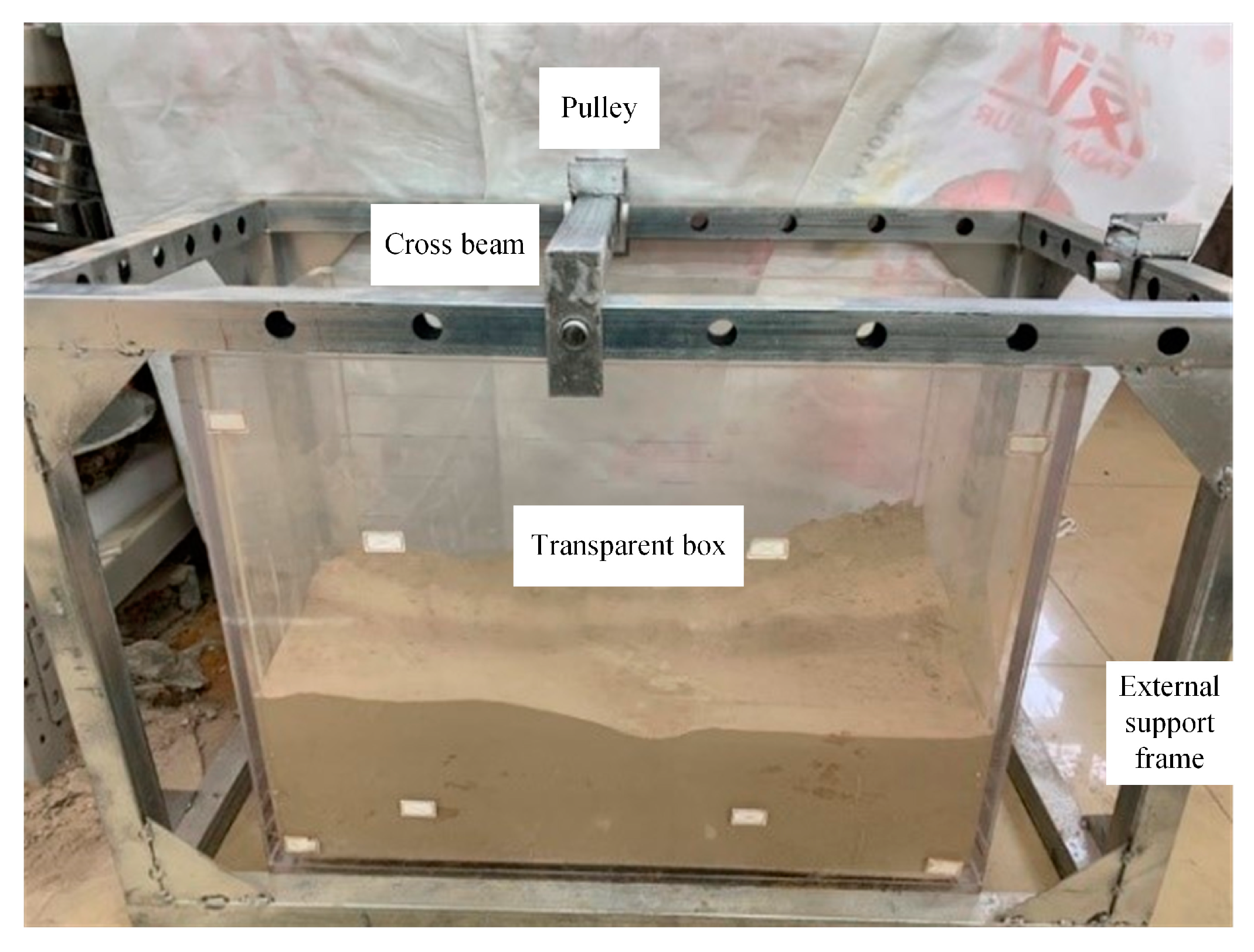
- One end of the traction rope is connected to the round hole at one end of the anchor rod, and it is connected with the anchor rod. The other end is connected with the weight disc, and the middle section of the traction rope is erected on the upper end and the side surface of the external support frame by virtue of the cross beam and the pulley frame. The overall diagram of the device is shown in Figure 5.
- (3)
- According to a certain weight gradient, more weights are gradually added to the weight plate; when the anchor is pulled out uniformly, weights are no longer added. The total mass of the weight plate is obtained using a tensiometer.
- (4)
- The anchor rod is replaced, steps 1, 2, and 3 are repeated, and the total mass value for the weight plate and weight when different anchor rods are pulled is recorded.
4.3. Results and Analysis
5. Analysis of Factors Influencing the Anchoring Mechanism of an Enlarged Head Anchor
5.1. Model Building and Parameter Selection
5.2. Influencing Factors and Measurement Point Arrangement
- (1)
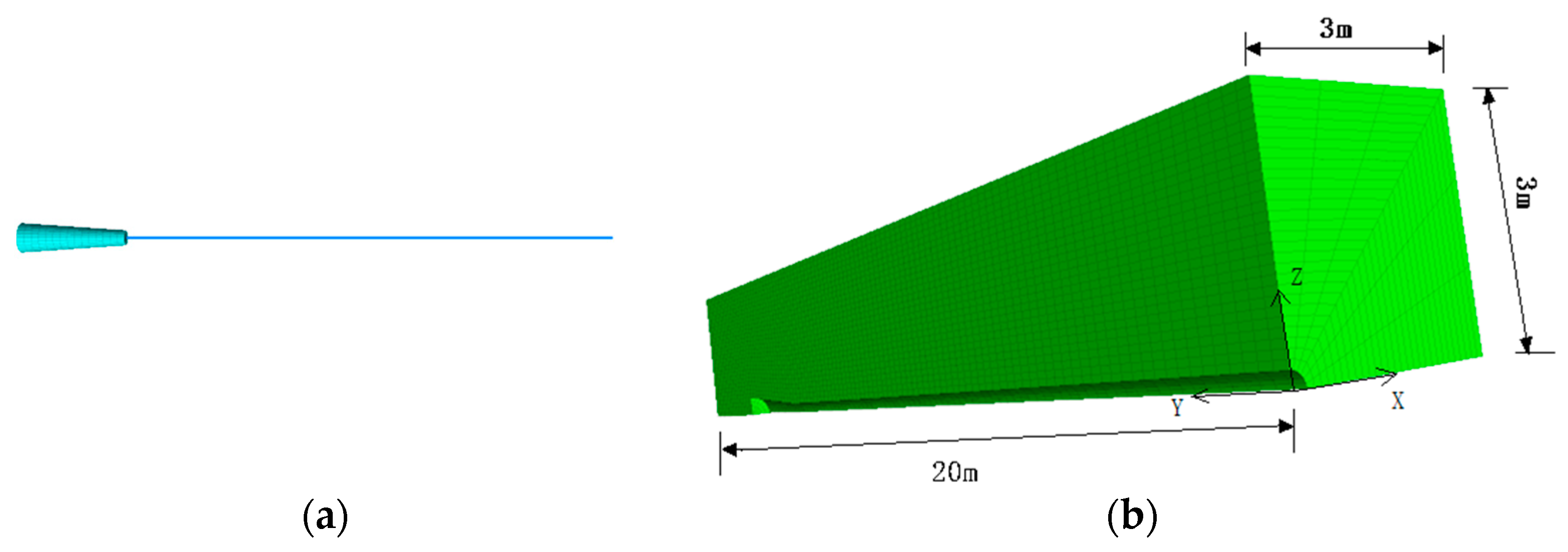
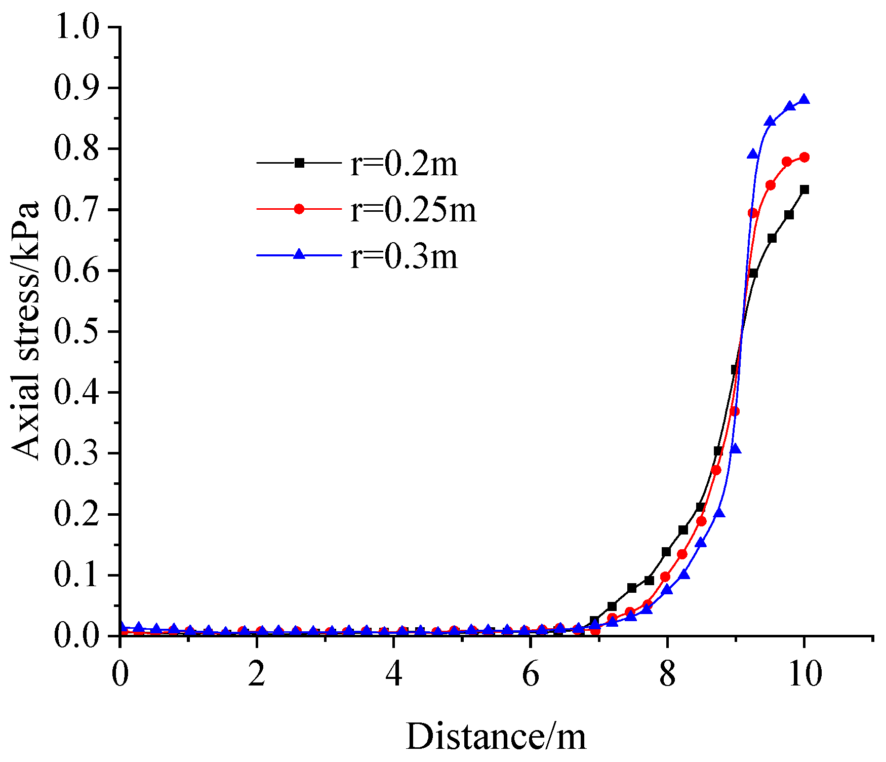
- When monitoring the anchor shaft force, the measurement points are arranged on the center axis of the inner anchorage section with the starting point coordinates (0, 14, 0) and the ending point coordinates (0, 14 + L, 0). The specific arrangement is shown in Figure 10a.
- (2)
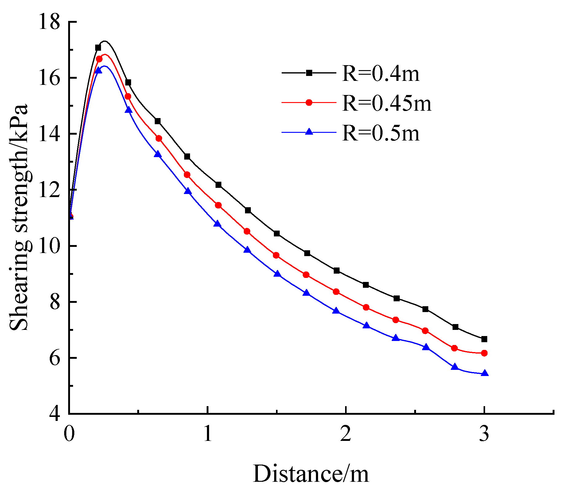
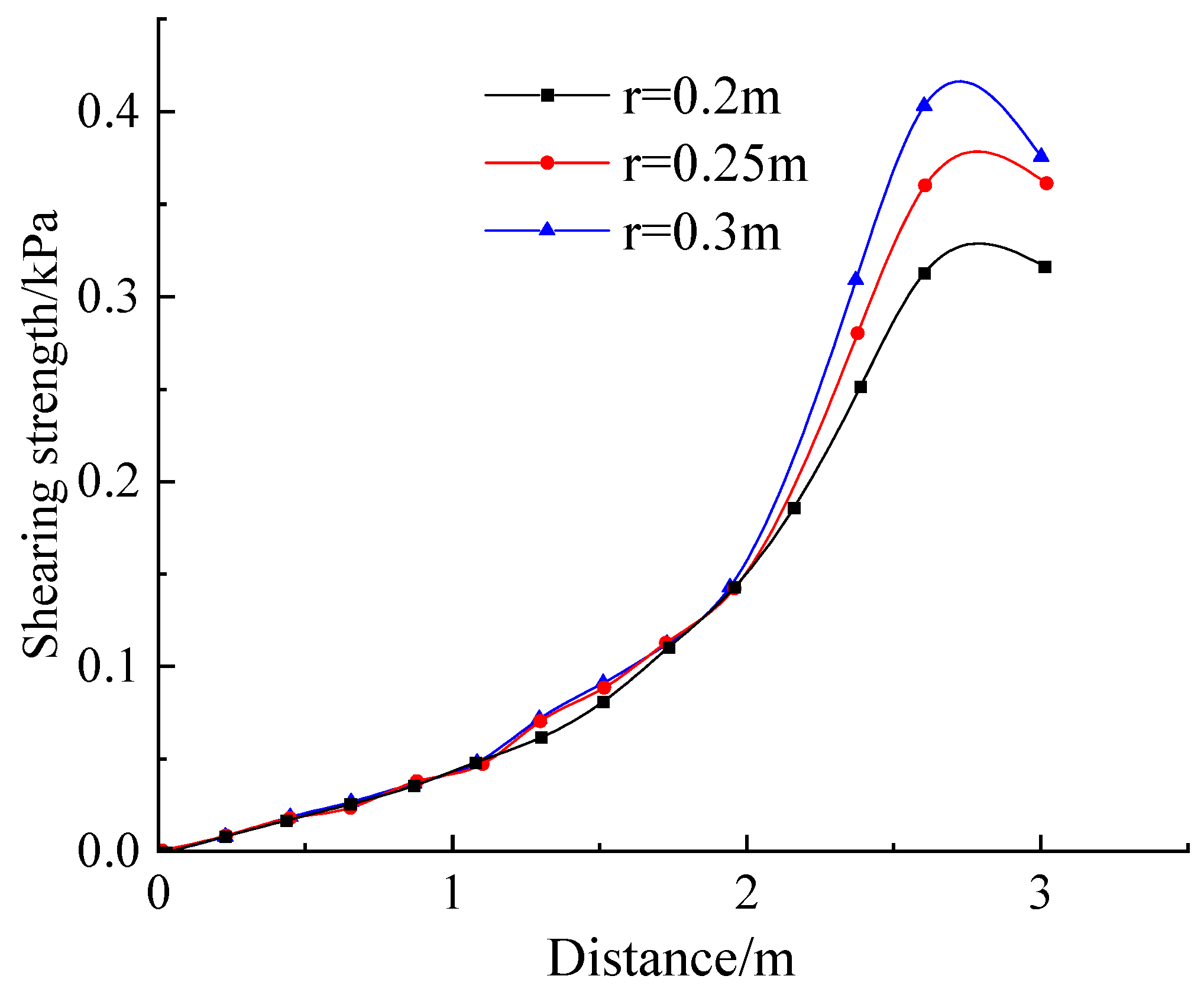
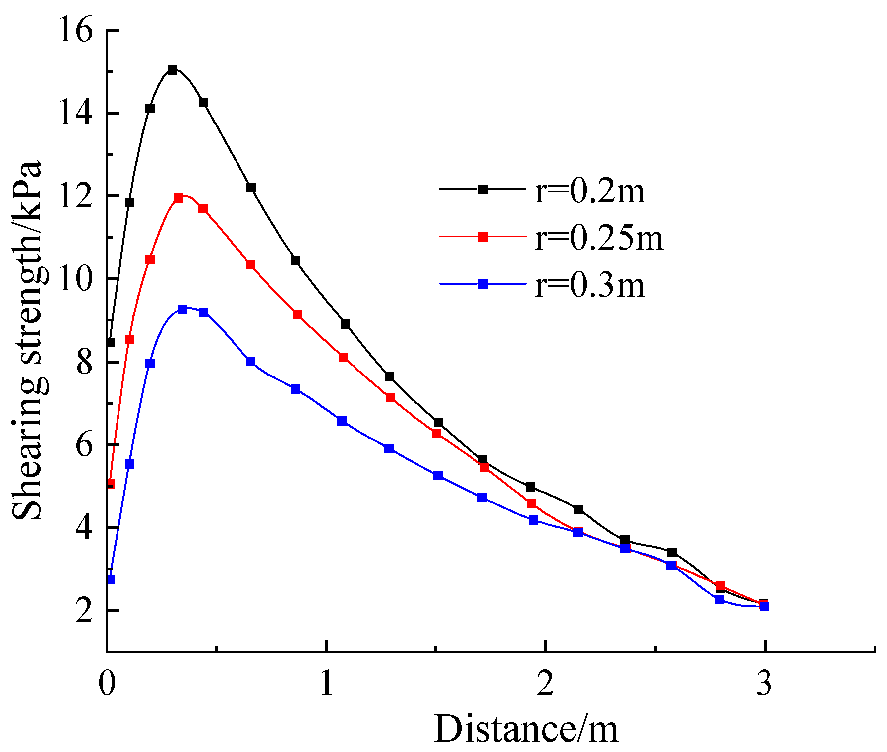
- When monitoring the shear stress on the outer side of the anchor, the measurement point is arranged at the outer edge of the inner anchorage section, with the coordinates of the starting point (0, 14, r) and the coordinates of the ending point (0, 14 + L, R), as shown in Figure 10b.
- (3)
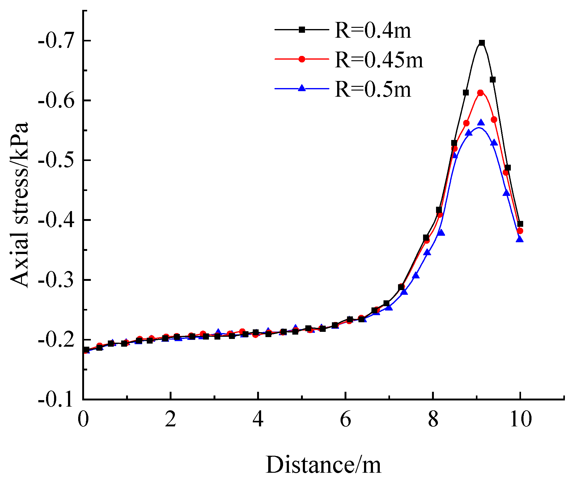
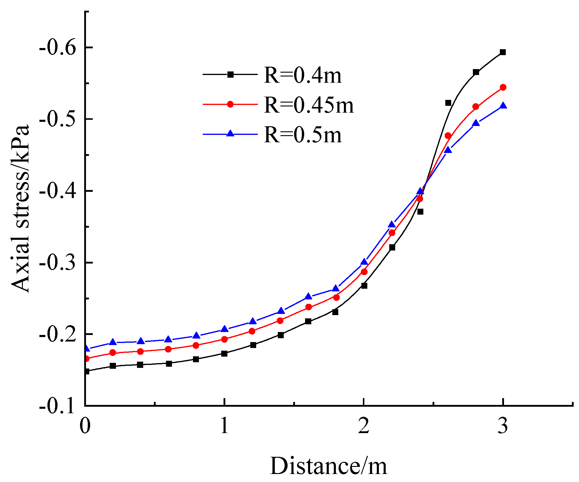
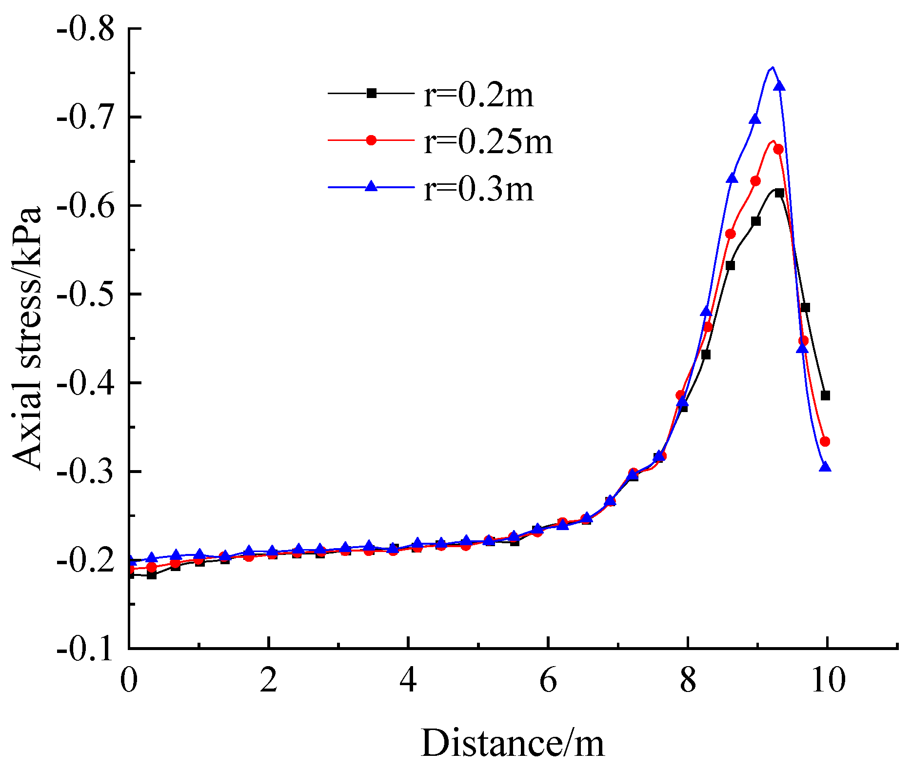
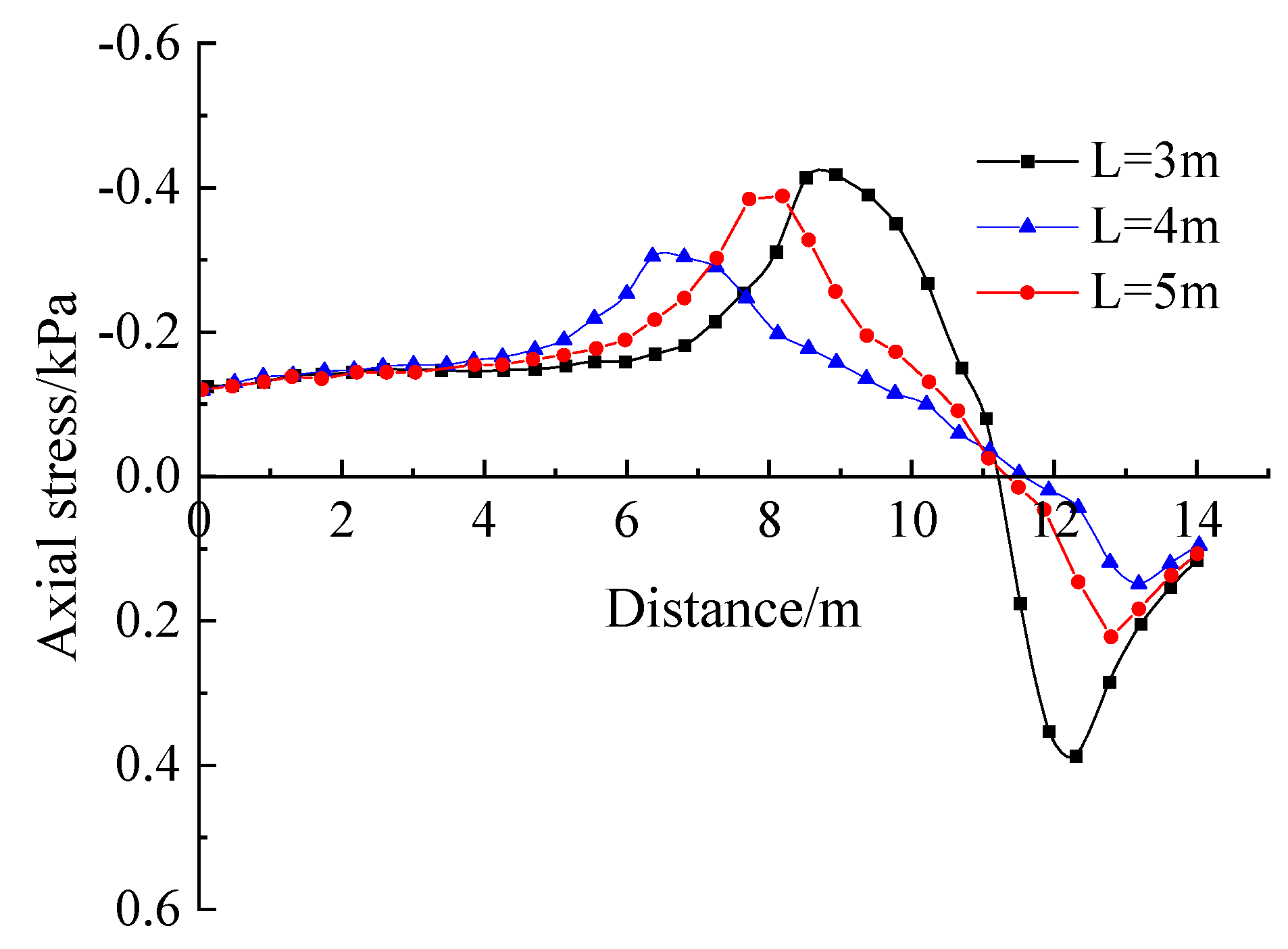
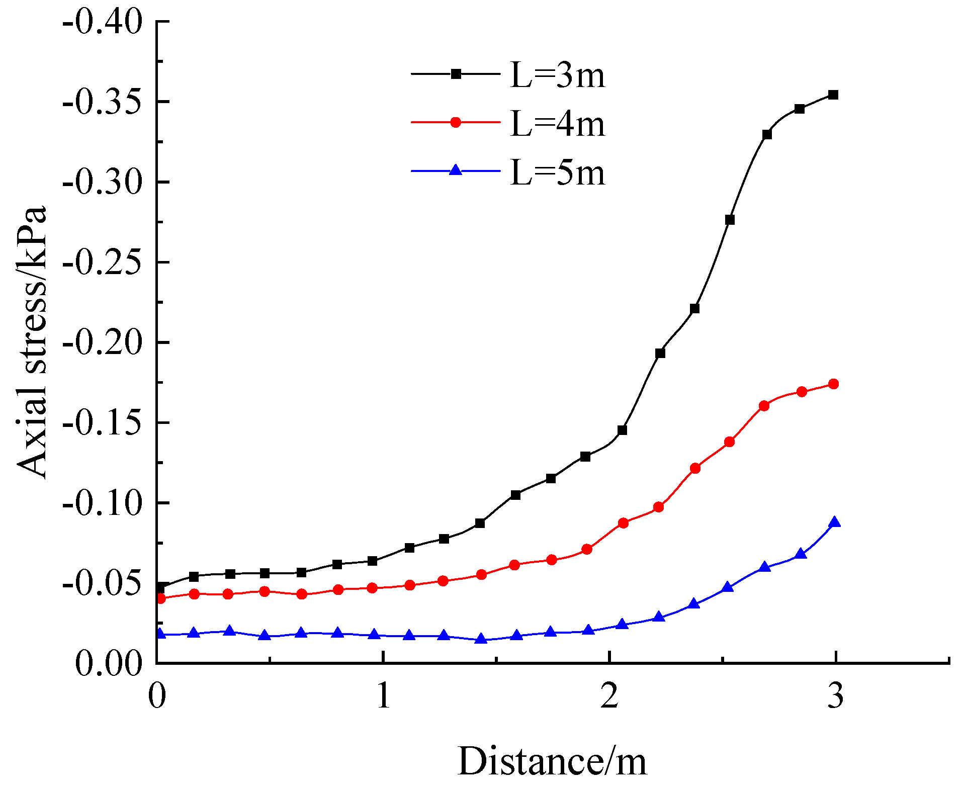
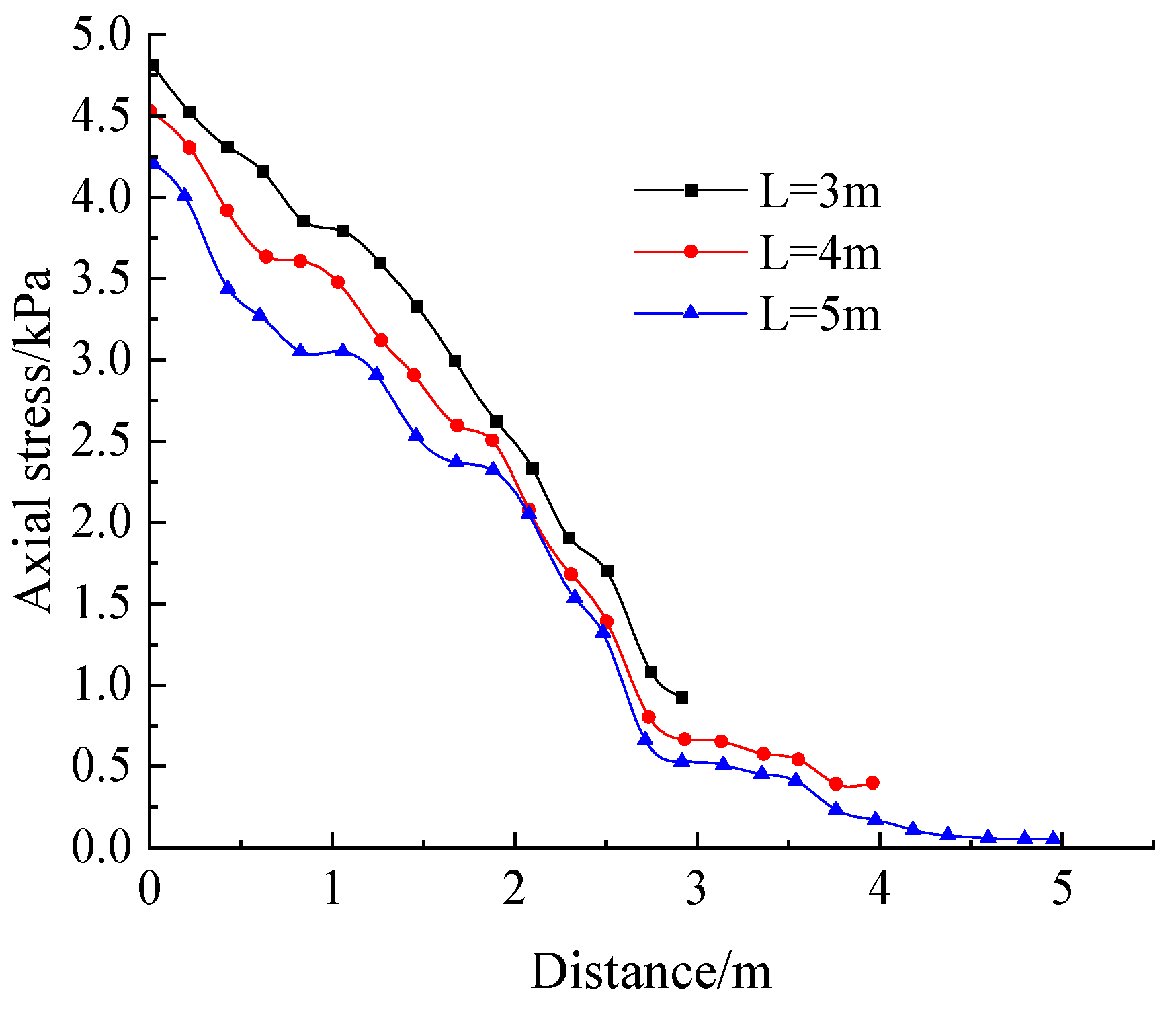
- To monitor the soil y-directional axial force and shear force more comprehensively, the measurement points are arranged mainly along two directions. For the first direction, the monitoring starting point coordinates are (0, 5, 0.5) and the end point coordinates are (0, 15, 0.5), hereinafter referred to as the horizontal direction; for the second direction, the monitoring starting point coordinates are (0.5, 15, 3) and the end point coordinates are (0.5, 15, 0), hereinafter referred to as the vertical direction. The specific arrangement is shown in Figure 10c.
5.3. Results and Analysis
- (1)
- Influence of inner anchorage section rear section radius R
- (2)
- Analysis of the effect of the rate of change in the anterior and posterior sections
- (3)
- Analysis of the effect of length L of the enlarged section
6. Conclusions
- (1)
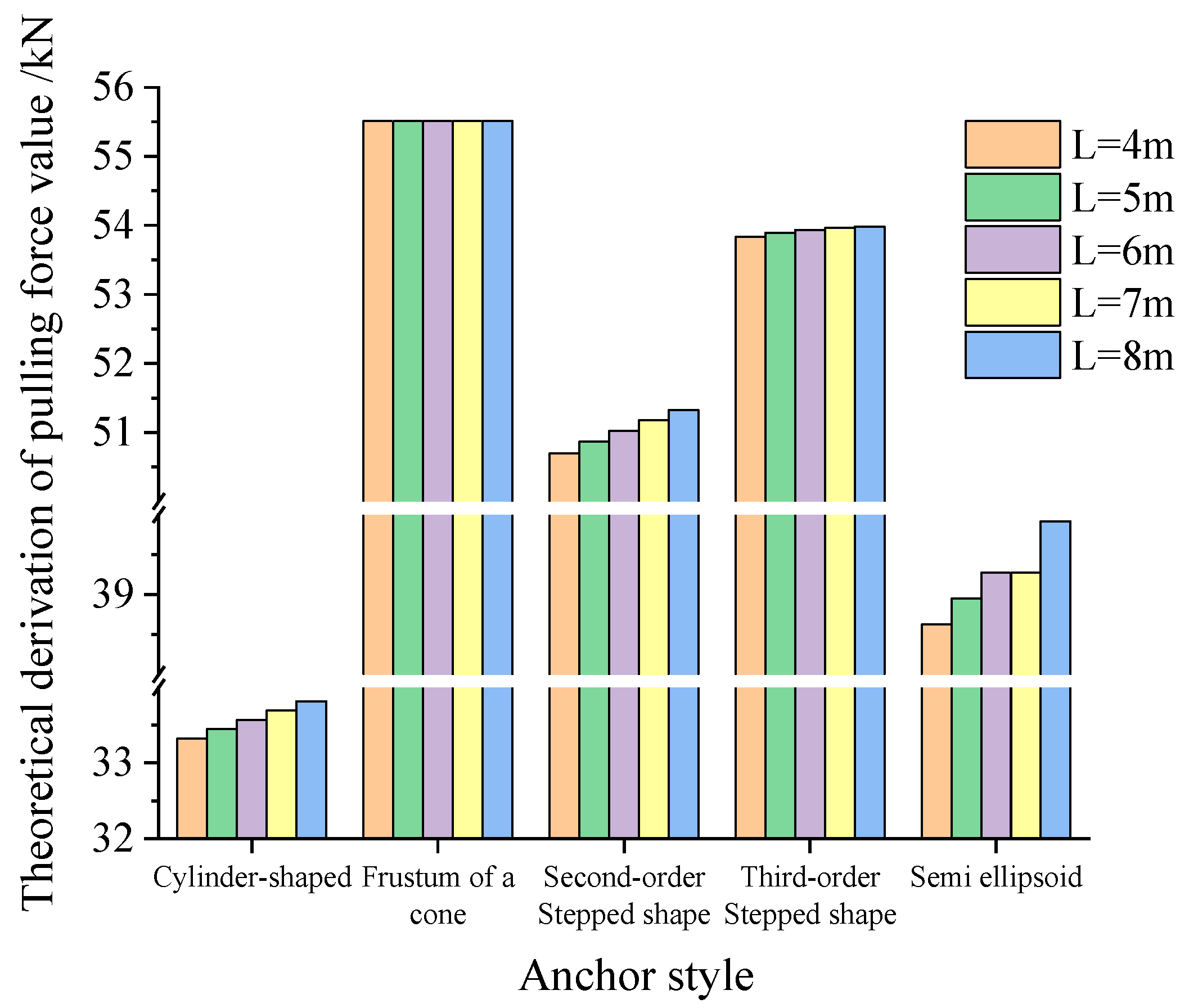
- Under the condition that the volume and length of the extended anchorage section are the same, the ultimate pulling capacity of the cylindrical enlarged head anchor is generally less than that of the circular, stepped, and semi-elliptic enlarged head anchor, and its value is about 0.2~0.5 times the latter three. Moreover, it increases with an increase in the anchoring section’s length. The ultimate uplift capacity of the circular table-shaped enlarged head anchor is obviously higher than that for the stepped, semi-elliptic and cylindrical enlarged head anchors. The ultimate uplift capacity of the circular table-shaped enlarged head anchor increases with the increase in anchorage length under the constant volume condition of the enlarged head anchor. The ultimate pulling capacity of a stepped enlarged head anchor is affected by its order and length of the anchoring section. With the increase in order n and anchoring section length L, the ultimate pulling capacity of the stepped enlarged head anchor increases. The ultimate pulling capacity of the semi-elliptic enlarged head anchor falls between the cylindrical and stepped enlarged head anchors, and its variation law is consistent with that for circular and stepped bolts. The longer the inner anchorage section, the larger the distribution range in the compression zone formed in the soil body, and the smaller the range in the tension zone formed in the rear section. The increase in the length of the inner anchoring section helps improve the reinforcement effect of the soil in front of the inner anchoring section; thus, the parameter plays an important role in the redistribution of soil that experiences the force.
- (2)
- The drawing capacity of the expanded head anchor is affected by the bearing capacity of the front and rear ends, the side bearing capacity, and the side friction resistance. For circular anchor bolts, stepped anchor bolts, and semi-ellipsoidal anchor bolts, with the increase in front section radius r, the lateral friction resistance in the inner anchoring section is gradually shared by the bearing force of the front end of the inner anchoring section; the front-end-bearing effect of the inner anchoring section is enhanced; the bolt’s pulling performance is enhanced. Therefore, the pull-out force of the circular rock bolt is the greatest, followed by that of the stepped rock bolt, and the pull-out force of the semi-elliptic rock bolt is the lowest. The increase in rear section R can provide greater lateral friction resistance and rear-end bearing capacity. Compared with cylindrical enlarged head anchors and circular, stepped, and semi-elliptic enlarged head anchors, although the front section is smaller, the rear section is larger. The bearing capacity of the front section decreases less than the side bearing capacity, and the rear bearing capacity increases; thus, the cylindrical bolt has the least pulling force. Compared with front radius r, back radius R has more influence on the drawing ability of the enlarged head anchor.
- (3)
- The numerical calculation and analysis model of the anchor rod with expanded horizontal pullout head was established by using the numerical calculation software FLAC 3D (Version 5.0.), and the effects of the parameters such as the diameter of the rear section of the inner anchorage section, the ratio of the radius of the front and rear sections, and the length of the inner anchorage section on the soil reinforcement effect, together with the force characteristics of the anchor rod itself, were analyzed in depth, and the significance of the effects of each parameter was compared. The results showed that increasing radius R of the rear section of the inner anchorage section helped to improve the reinforcement effect of the soil perpendicular to the distribution direction of the anchor rod; decreasing the change rate in the front and rear sections and increasing length L of the inner anchorage section helped to improve the reinforcement effect of the soil in front of the inner anchorage section of the anchor rod, and the latter was better than the former.
Author Contributions
Funding
Informed Consent Statement
Data Availability Statement
Conflicts of Interest
Appendix A
- (1)
- The derivation of the formula for the back section radius of the inner anchorage section of the stepped enlarged head anchor rod.The volume of the stepped anchor rod is as follows:The following is obtained:
- (2)
- The derivation of pulling force by the side friction of the stepped enlarged head anchor:
- (3)
- The derivation of pulling force by the side friction of the semi-ellipsoid head anchor. We obtain the following:
References
- Majer, J. Zur berechnung von zugfundamenten. Osterreichische Bauz. 1955, 10, 5–6. [Google Scholar]
- Mors, H. The behaviour of mast foundations subjected to tensile forces. Bautechnik 1959, 36, 367–378. [Google Scholar]
- Teng, W.C. Foundation Design; Prentice-Hall: Hoboken, NJ, USA, 1962; Volume 1, pp. 138–139. [Google Scholar]
- Choudhary, A.K.; Dash, S.K. Load-Carrying Mechanism of Vertical Plate Anchors in Sand. Int. J. Geomech. 2016, 17, 04016116.1–04016116.12. [Google Scholar] [CrossRef]
- Mariupol’Skii, L.G. The bearing capacity of anchor foundations. Soil Mech. Found. Eng. 1965, 2, 26–32. [Google Scholar] [CrossRef]
- Hsu, S.T.; Liao, H.J. Uplift behaviour of cylindrical anchors in sand. Can. Geotech. J. 1998, 12, 70–80. [Google Scholar] [CrossRef]
- Meyerhof, G.G.; Adams, J.I. The Ultimate Uplift Capacity of Foundations. Can. Geotech. J. 1968, 5, 225–244. [Google Scholar] [CrossRef]
- Prakash, C.; Ramakrishna, V. Lateral load capacity of underreamed piles—An analytical approach. Soils Found. 2008, 44, 51–65. [Google Scholar] [CrossRef]
- Alekseev, A.G.; Bezvolev, S.G.; Sazonov, P.M. Experience of using multi-blade screw piles in silt-loam soil foundation. Soil Mech. Found. Eng. 2019, 55, 388–393. [Google Scholar] [CrossRef]
- Niroumand, H.; Kassim, K.A. Uplift Response of Irregular-Shaped Anchor in Cohesionless Soil. Arab. J. Sci. Eng. 2014, 39, 3511–3524. [Google Scholar] [CrossRef]
- Shahin, M.A.; Jaksa, M.B. Pullout capacity of small ground anchors by direct cone penetration test methods and neural networks. Can. Geotech. J. 2006, 43, 626–637. [Google Scholar] [CrossRef]
- Rafa, S.A.; Moussai, B. Three-dimensional analyses of bored pile and barrette load tests subjected to vertical loadings. Soil Mech. Found. Eng. 2018, 5, 146–152. [Google Scholar] [CrossRef]
- Park, H.; Lee, S.R.; Kim, N.K.; Kim, T.H. A numerical study of the pullout behavior of grout anchors underreamed by pulse discharge technology. Comput. Geotech. 2013, 47, 78–90. [Google Scholar] [CrossRef]
- Golait, Y.S.; Padade, A.H.; Cherian, T. Prediction of Quantitative Response of Under-Reamed Anchor Piles in Soft Clay Using Laboratory Model Study. J. Test. Eval. 2018, 46, 507–522. [Google Scholar] [CrossRef]
- Jeong, S.Y.; Choi, H.Y.; Lee, S.R. Uplift Behavior of Under-Reamed Anchors in Sandbed. Int. J. Offshore Polar Eng. 2007, 17, 317–319. [Google Scholar]
- Chen, C.; Xia, Y.Y.; Ni, Q. Investigation on the Working Mechanism and Structural Parameters Optimization of Multiple Ball Shaped Nodular Anchors. Soil Mech. Found. Eng. 2020, 57, 49–56. [Google Scholar] [CrossRef]
- Liao, H.J.; Hsu, S.J. Uplift Behavior of Blade-Underreamed Anchors in Silty Sand. J. Geotech. Geoenviron. Eng. 2003, 6, 129–130. [Google Scholar] [CrossRef]
- Murray, E.J.; Geddes, J.D. Uplift of Anchor Plates in Sand. J. Geotech. Eng. 1987, 113, 202–215. [Google Scholar] [CrossRef]
- Matsuo, M. Study on the uplift resistance of footing (II). Soils Found. 1968, 8, 18–48. [Google Scholar] [CrossRef]
- Zhou, Z.; Zhang, L.; Han, P. Field comparative test of high pressure rotary jet enlarged head anchor. Eng. Investig. 2019, 10, 32–34. (In Chinese) [Google Scholar]
- Giampa, J.R.; Bradshaw, A.S.; Gerkus, H.; Gilbert, R.B.; Sivakumar, V. The effect of shape on the pull-out capacity of shallow plate anchors in sand. Geotechnique 2019, 69, 355–363. [Google Scholar] [CrossRef]
- Wang, L.; Li, J.; Wen, P. Research on bearing characteristics of enlarged head anchorage bar. Southwest Highw. 2016, 3, 49–56. (In Chinese) [Google Scholar]
- Liang, Y. Study on Anchoring Mechanism of Pressure Type Anchor with Reaming Hole in Soil Layer; China Academy of Railway Sciences: Beijing, China, 2012. (In Chinese) [Google Scholar]
- Zhang, H. Study on Mechanical Mechanism of Enlarged Head Anchor. Master’s Thesis, Hebei University of Engineering, Handan, China, 2018. (In Chinese). [Google Scholar]
- Cui, X.; He, W. Stress analysis of anchorage section of extended large anchor bolt under drawing action. Chin. Sci. Technol. Pap. 2013, 8, 381–384. (In Chinese) [Google Scholar] [CrossRef]
- Guo, G.; Liu, Z.; Li, Y.; Yang, S.; Zhang, Y. Model experimental study on pull-out failure mechanism of expanded bolt. Chin. J. Rock Mech. Eng. 2013, 32, 1677–1684. (In Chinese) [Google Scholar]
- Zeng, Q.; Yang, X.; Yang, Y. Mechanical mechanism and calculation method of enlarged head anchor. Rock Soil Mech. 2010, 31, 1359–1367. (In Chinese) [Google Scholar] [CrossRef]
- Ilamparuthi, K.; Muthukrishnaiah, K. Anchors in sand bed: Delineation of rupture surface. Ocean Eng 1999, 26, 1249–1273. [Google Scholar] [CrossRef]
- Ghaly, A.; Hanna, A.; Hanna, M. Uplift behaviour of screw anchors in sand. II: Hydrostatic and flow conditions. Int. J. Rock Mech. Min. Sci. Geomech. Abstr. 1991, 28, 794–808. [Google Scholar] [CrossRef]
- Guo, W.; Li, C.; Gong, X.; Li, J.; Xiong, Z. Calculation and analysis of influencing factors of pullout resistance of enlarged head bolt. Geotech. Found. 2012, 26, 52–55. (In Chinese) [Google Scholar] [CrossRef]
- Technical Code for Geotechnical Bolt and Shotcrete Support Engineering; China Plan Publishing House: Beijing, China, 2015. (In Chinese)
- Li, Y.; Wang, L.; Feng, Z.; Lei, D.; Han, Y. Theoretical Analysis and Numerical Simulation of Bearing Characteristics of Anti-anchor Bolt with Enlarged Head. Southwest Highw. 2017, 3, 150–155. (In Chinese) [Google Scholar]
- Yuan, W. Similarity Theory and Static Model Test; Southwest Jiaotong University Press: Chengdu, China, 1998. (In Chinese) [Google Scholar]
- Ma, X. Experimental Study and Numerical Analysis of 3D Soil Arching in Piled Reinforced Embankments. Master’s Thesis, Chang’an University, Xi’an, China, 2018. Available online: https://xueshu.baidu.com/usercenter/paper/show?paperid=1q2t00e04w2r0270hk1c0ex0u5412423&site=xueshu_se (accessed on 14 April 2023). (In Chinese).
- Wen, P. Experimental Study on Load-Bearing Characteristics of Anchor Rod with Expanded Head. Master’s Thesis, Zhengzhou University, Zhengzhou, China, 2016. Available online: https://xueshu.baidu.com/usercenter/paper/show?paperid=32de6c152c6c0dffe56a52d2cf65bf2a&site=xueshu_se&hitarticle=1 (accessed on 14 April 2023). (In Chinese).
- Chang, S. Handbook of Engineering Geology; Architecture and Building Press: Beijing, China, 2013. (In Chinese) [Google Scholar]
- GB/T5224-2003; Steel Strand for Pre-Stressed Concrete. Standard Press of China: Beijing, China, 2003. (In Chinese)
- Fu, W.; Zhuo, Z.; Ren, X. Experimental study on the adhesive strength of anchor slurry and tendon in soil layer. J. Geotech. Eng. 2018, 40, 1300–1308. (In Chinese) [Google Scholar] [CrossRef]
- Zhang, Y.; Rao, L.; Tang, S.; Xu, M.; Luo, B. Shear strength test of prestressed anchor cable grouted body and rock bonding interface. Chin. J. Highw. 2008, 6, 1–6. (In Chinese) [Google Scholar]












| Parameter | K | ||
|---|---|---|---|
| Value range and value | 0.10~0.15 | 2.0 | 1.3~1.6 |
| Soil Type | |||
|---|---|---|---|
| Sandy soil | 18 | 0 | 20 |
| Length of the Internal Anchorage Section | ||||||
|---|---|---|---|---|---|---|
| 4 m | 5 m | 6 m | 7 m | 8 m | ||
| Theoretical derivation of pulling force value/kN | Cylinder-shaped | 33.32513 | 33.44759 | 33.57005 | 33.69251 | 33.81497 |
| Frustum of a cone | 55.5145 | 55.51451 | 55.51452 | 55.51452 | 55.51452 | |
| Second-order Stepped shape | 50.69843 | 50.86896 | 51.02736 | 51.17883 | 51.32597 | |
| Third-order Stepped shape | 53.83549 | 53.89467 | 53.93413 | 53.96231 | 53.98345 | |
| Semi-ellipsoid | 38.62513 | 38.94759 | 39.27005 | 39.27005 | 39.91497 | |
| Similarity Criterion | Similarity Constant |
|---|---|
| π1m = π1p | = 20 |
| π2m = π2p | γ = 1 |
| π3m = π3p | E = 20 |
| π4m = π4p | Cμ = 1 |
| Group Number | Cylinder-Shaped | Frustum of a Cone | Stepped Shape | Semi-Ellipsoid | ||
|---|---|---|---|---|---|---|
| 1 | 2 | 3 | 4 | 5 | 6 | |
| Bolt size/cm | r = R = 2.5 L = 10 | r = 2.1 R = 2.9 L = 10 | r = 1.6 R = 3.4 L = 10 | = 3.1 L = 10 | = 3.3 L = 10 | a = 2.7 b = 3.5 c = 10 |
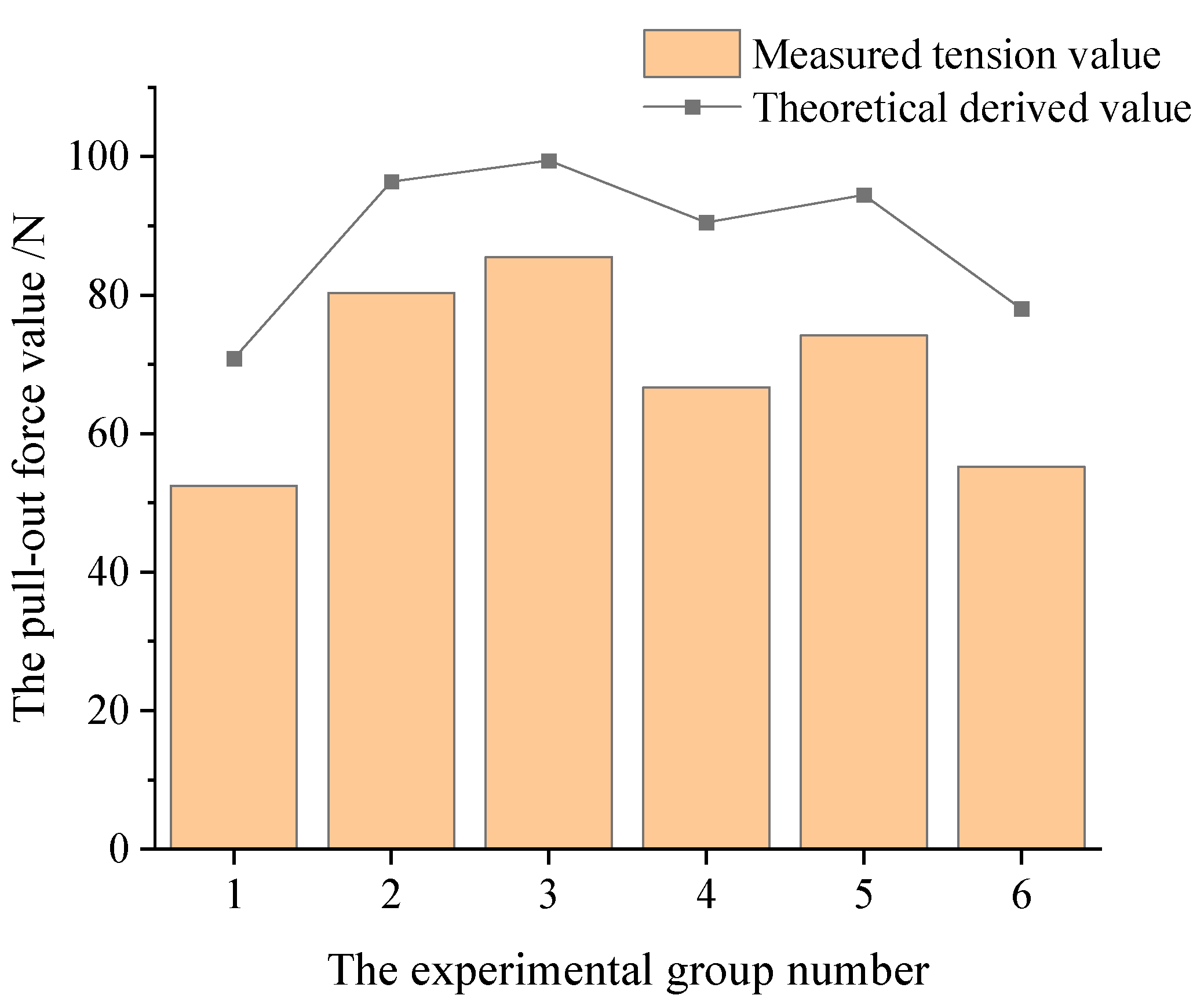
| Check and derive the theoretical value/N | 70.809 | 96.382 | 99.386 | 90.461 | 94.461 | 78.037 |
| 196.25 | ||||||
| Measured value for pulling force/N (g = 9.8 N/kg) | 53.214 | 81.144 | 86.632 | 68.698 | 74.676 | 56.252 |
| 52.038 | 80.556 | 86.142 | 67.228 | 74.284 | 55.468 | |
| 52.822 | 80.360 | 84.476 | 65.954 | 73.500 | 55.370 | |
| 51.842 | 79.086 | 84.672 | 64.876 | 74.186 | 53.802 | |
| Severe γ (kN/m3) | Poisson’s Ratio μ | Modulus of Elasticity E (MPa) |
|---|---|---|
| 25 | 0.2 | 33,500 |
| Name | Anchor Cable Modulus of Elasticity (GPa) | Adhesion Strength of Anchored Section/(MPa) | Friction Angle of Anchorage Section (°) | Anchorage Section Perimeter (m) | Anchor Cable Cross-Sectional Area (mm2) | Yield Strength of Anchor Cable (kN) |
|---|---|---|---|---|---|---|
| Free section | 195 | 0 | 0 | 0.040 | 98 | 203 |
| Anchorage section | 195 | 0.7 | 38 | 0040 | 98 | 203 |
| Normal Stiffness (MPa/m) | Tangential Stiffness (MPa/m) | Shear Strength (kPa) | Tensile Strength (kPa) | Friction Angle (°) | Expansion Angle (°) | Cohesion (kPa) |
|---|---|---|---|---|---|---|
| 20 | 10 | 3.45 | 1.15 | 20.0 | 20.0 | 5 |
| Simulation Group Serial Number | Radius of Section Before Inner Anchorage Section (r/m) | Radius of Section After Inner Anchorage Section (R/m) | Length ofInternal Anchorage Section Segment (L/m) | Volume of Inner Anchorage Section (V/m3) | |
|---|---|---|---|---|---|
| ① | 0.2 | 0.4 | 3 | 0.2/3 | 1 V |
| ② | 0.2 | 0.45 | 3 | 0.25/3 | 1.4 V |
| ③ | 0.2 | 0.5 | 3 | 0.3/3 | 1.9 V |
| ④ | 0.25 | 0.4 | 3 | 0.15/3 | 2.3 V |
| ⑤ | 0.3 | 0.4 | 3 | 0.1/3 | 2.7 V |
| ⑥ | 0.2 | 0.4 | 4 | 0.2/4 | 2 V |
| ⑦ | 0.2 | 0.4 | 5 | 0.2/5 | 2.2 V |
| ⑧ | 0.2 | 0.4 | 6 | 0.2/6 | 2.8 V |
Disclaimer/Publisher’s Note: The statements, opinions and data contained in all publications are solely those of the individual author(s) and contributor(s) and not of MDPI and/or the editor(s). MDPI and/or the editor(s) disclaim responsibility for any injury to people or property resulting from any ideas, methods, instructions or products referred to in the content. |
© 2023 by the authors. Licensee MDPI, Basel, Switzerland. This article is an open access article distributed under the terms and conditions of the Creative Commons Attribution (CC BY) license (https://creativecommons.org/licenses/by/4.0/).
Share and Cite
Zhang, S.; Wang, Y.; Li, C.; Wang, C.; Zhang, G.; Sun, S. Study on the Style Design and Anchoring Mechanism of Enlarged Head Anchors. Sustainability 2023, 15, 8645. https://doi.org/10.3390/su15118645
Zhang S, Wang Y, Li C, Wang C, Zhang G, Sun S. Study on the Style Design and Anchoring Mechanism of Enlarged Head Anchors. Sustainability. 2023; 15(11):8645. https://doi.org/10.3390/su15118645
Chicago/Turabian StyleZhang, Sifeng, Yushuai Wang, Chao Li, Changwei Wang, Guojian Zhang, and Shengzhi Sun. 2023. "Study on the Style Design and Anchoring Mechanism of Enlarged Head Anchors" Sustainability 15, no. 11: 8645. https://doi.org/10.3390/su15118645
APA StyleZhang, S., Wang, Y., Li, C., Wang, C., Zhang, G., & Sun, S. (2023). Study on the Style Design and Anchoring Mechanism of Enlarged Head Anchors. Sustainability, 15(11), 8645. https://doi.org/10.3390/su15118645


