
Electro-Conversion of Carbon Dioxide to Valuable Chemicals in a Membrane Electrode Assembly

Abstract
:1. Introduction
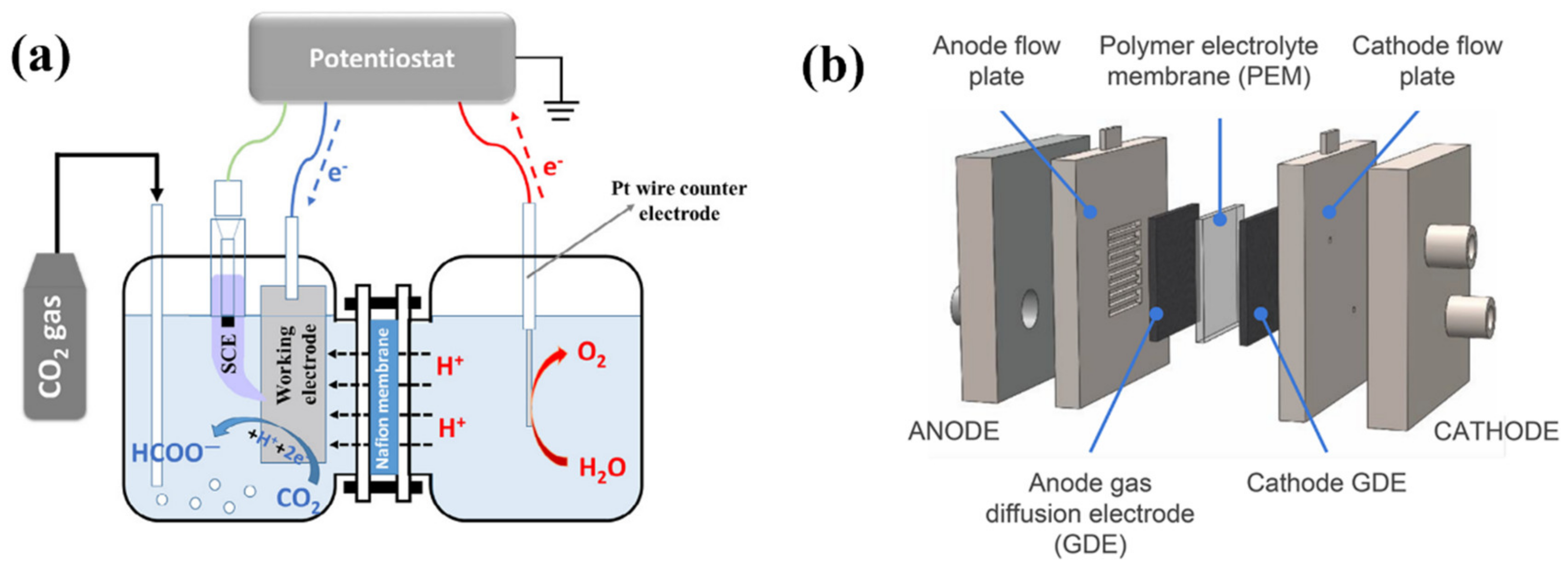
2. Configuration
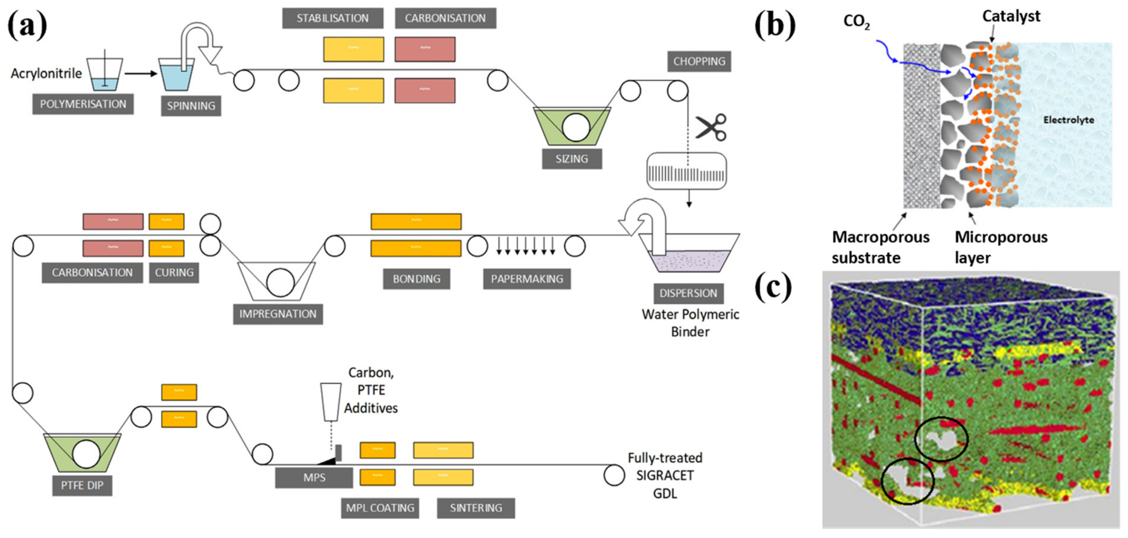
2.1. Gas Diffusion Electrode (GDE) for ECO2RR
2.1.1. Gas Diffusion Layer (GDL)
2.1.2. Catalyst Layer (CL)
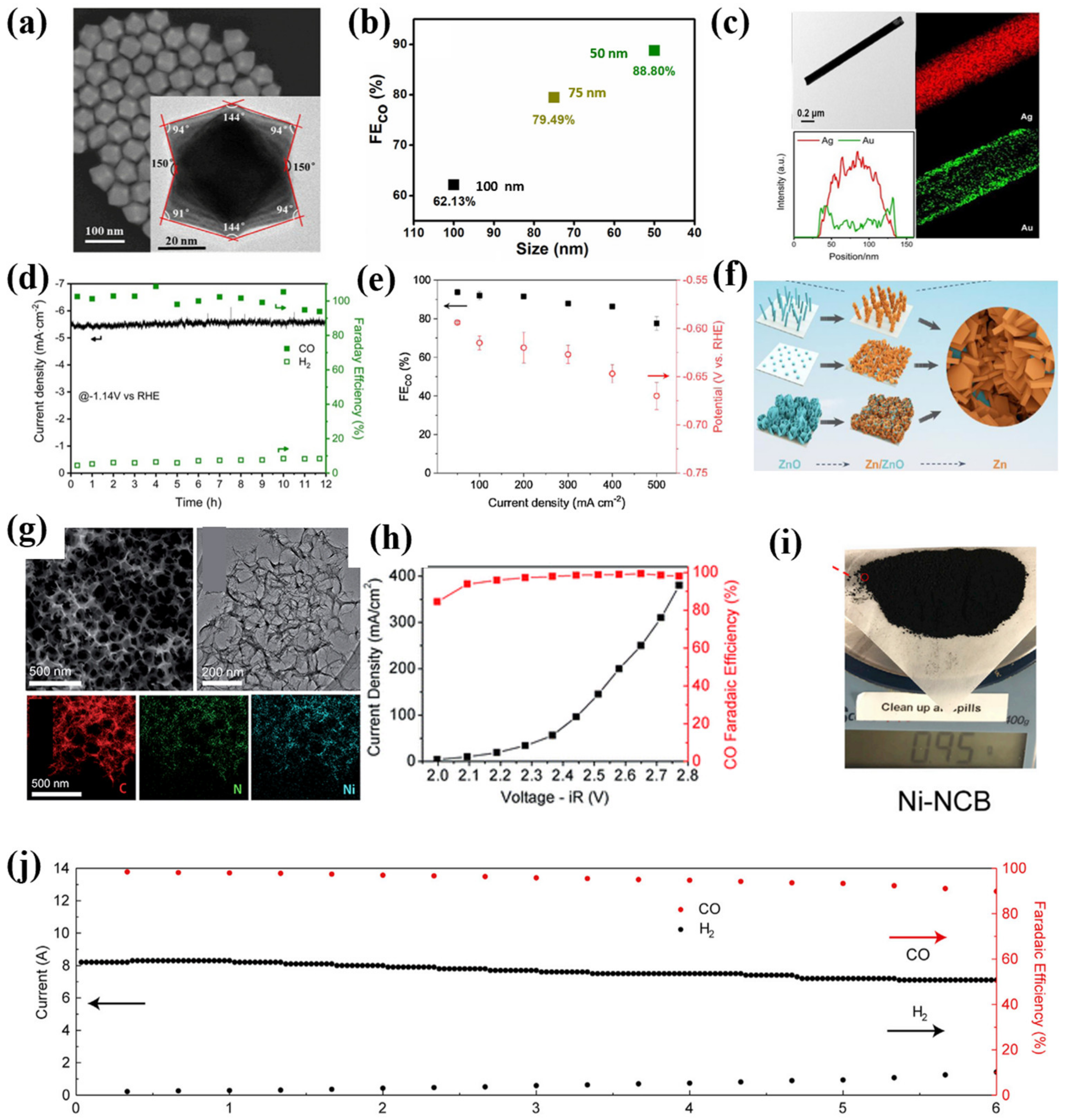
Catalyst for Single-Carbon Products (C1) Generation
Catalyst for Multiple-Carbon Products (C2+) Generation
2.1.3. Catalyst Layer Preparation
2.2. Membrane
2.2.1. Anion Exchange Membrane
2.2.2. Cation Exchange Membrane
2.2.3. Bipolar Membrane
3. The Significance of pH, Anion, and Cation
3.1. The Effects of pH
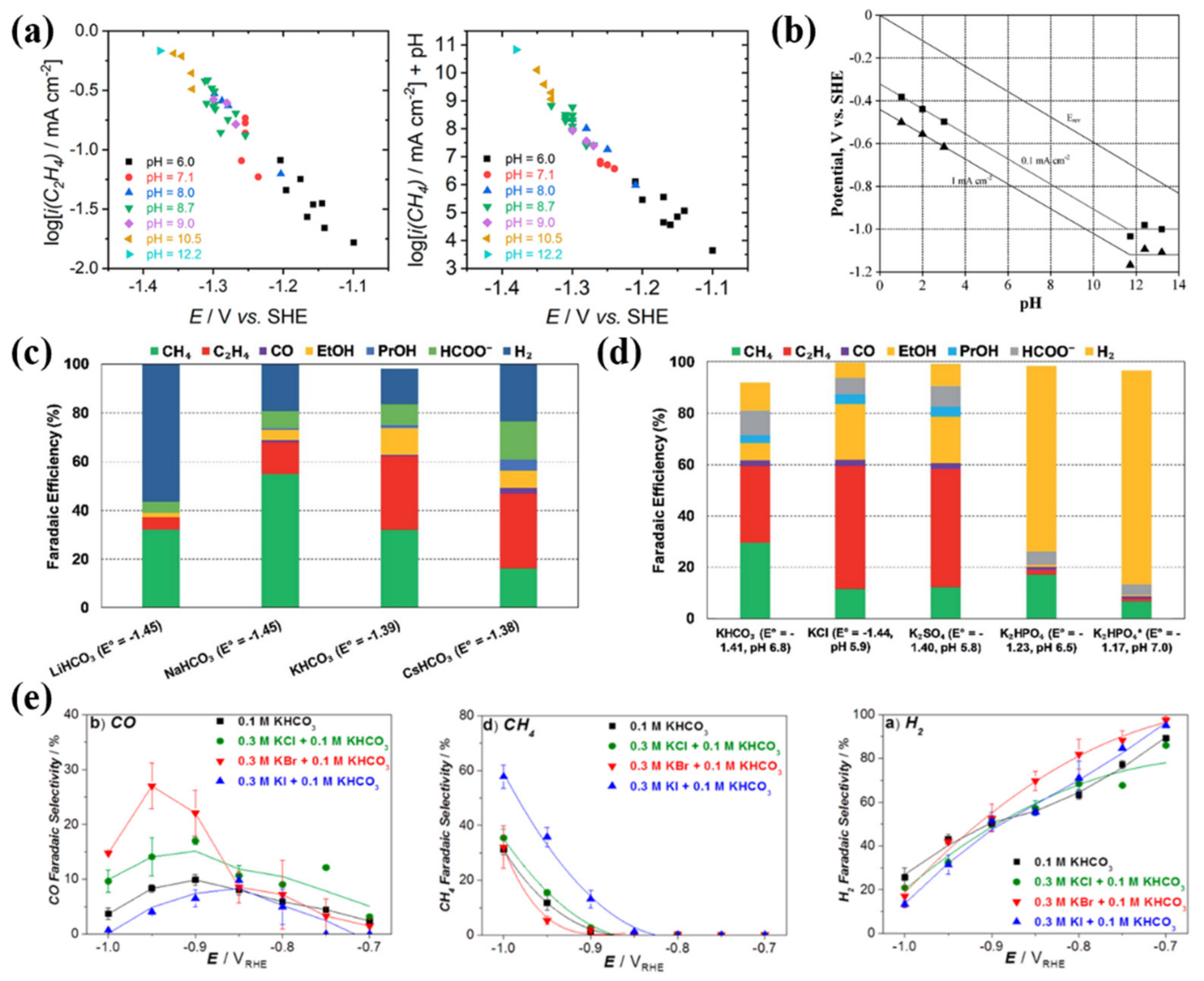
3.2. The Effect of Cation
3.3. The Effect of Anion
4. Microfluidic Flow Cells
5. Summary and Outlook
Funding
Institutional Review Board Statement
Informed Consent Statement
Data Availability Statement
Conflicts of Interest
References
- Cavicchioli, R.; Ripple, W.J.; Timmis, K.N.; Azam, F.; Bakken, L.R.; Baylis, M.; Behrenfeld, M.J.; Boetius, A.; Boyd, P.W.; Classen, A.T.; et al. Webster, Scientists’ warning to humanity: Microorganisms and climate change. Nat. Rev. Microbiol. 2019, 17, 569–586. [Google Scholar] [CrossRef] [PubMed] [Green Version]
- Yalew, S.G.; van Vliet, M.T.H.; Gernaat, D.E.H.J.; Ludwig, F.; Miara, A.; Park, C.; Byers, E.; de Cian, E.; Piontek, F.; Iyer, G.; et al. Impacts of climate change on energy systems in global and regional scenarios. Nat. Energy 2020, 5, 794–802. [Google Scholar] [CrossRef]
- Dai, A.; Luo, D.; Song, M.; Liu, J. Arctic amplification is caused by sea-ice loss under increasing CO2. Nat. Commun. 2019, 10, 121. [Google Scholar] [CrossRef] [PubMed] [Green Version]
- Nitopi, S.; Bertheussen, E.; Scott, S.B.; Liu, X.; Engstfeld, A.K.; Horch, S.; Seger, B.; Stephens, I.E.L.; Chan, K.; Hahn, C.; et al. Progress and Perspectives of Electrochemical CO2 Reduction on Copper in Aqueous Electrolyte. Chem. Rev. 2019, 119, 7610–7672. [Google Scholar] [CrossRef] [PubMed] [Green Version]
- Fan, L.; Xia, C.; Yang, F.; Wang, J.; Wang, H.; Lu, Y. Strategies in catalysts and electrolyzer design for electrochemical CO2 reduction toward C2+ products. Sci. Adv. 2020, 6, 910–918. [Google Scholar] [CrossRef] [Green Version]
- Weekes, D.M.; Salvatore, D.A.; Reyes, A.; Huang, A.; Berlinguette, C.P. Electrolytic CO2 Reduction in a Flow Cell. Acc. Chem. Res. 2018, 51, 910–918. [Google Scholar] [CrossRef]
- Liang, S.; Altaf, N.; Huang, L.; Gao, Y.; Wang, Q. Electrolytic cell design for electrochemical CO2 reduction. J. CO2 Util. 2020, 35, 90–105. [Google Scholar] [CrossRef]
- Malkhandi, S.; Yeo, B.S. Electrochemical conversion of carbon dioxide to high value chemicals using gas-diffusion electrodes. Curr. Opin. Chem. Eng. 2019, 26, 112–121. [Google Scholar] [CrossRef]
- Wilson, I.A.G.; Staffell, I. Rapid fuel switching from coal to natural gas through effective carbon pricing. Nat. Energy 2018, 3, 365–372. [Google Scholar] [CrossRef]
- Rumayor, M.; Dominguez-Ramos, A.; Perez, P.; Irabien, A. A techno-economic evaluation approach to the electrochemical reduction of CO2 for formic acid manufacture. J. CO2 Util. 2019, 34, 490–499. [Google Scholar] [CrossRef]
- Jouny, M.; Luc, W.; Jiao, F. General Techno-Economic Analysis of CO2 Electrolysis Systems. Ind. Eng. Chem. Res. 2018, 57, 2165–2177. [Google Scholar] [CrossRef]
- Kim, D.; Kley, C.S.; Li, Y.; Yang, P. Copper nanoparticle ensembles for selective electroreduction of CO2 to C2–C3 products. Proc. Natl. Acad. Sci. USA 2017, 114, 10560–10565. [Google Scholar] [CrossRef] [Green Version]
- Gabardo, C.M.; O’Brien, C.P.; Edwards, J.P.; McCallum, C.; Xu, Y.; Dinh, C.T.; Li, J.; Sargent, E.H.; Sinton, D. Continuous Carbon Dioxide Electroreduction to Concentrated Multi-carbon Products Using a Membrane Electrode Assembly. Joule 2019, 3, 2777–2791. [Google Scholar] [CrossRef]
- Kim, T.; Palmore, G.T.R. A scalable method for preparing Cu electrocatalysts that convert CO2 into C2+ products. Nat. Commun. 2020, 11, 3622. [Google Scholar] [CrossRef]
- Zhu, Q.; Sun, X.; Yang, D.; Ma, J.; Kang, X.; Zheng, L.; Zhang, J.; Wu, Z.; Han, B. Carbon dioxide electroreduction to C2 products over copper-cuprous oxide derived from electrosynthesized copper complex. Nat. Commun. 2019, 10, 3851. [Google Scholar] [CrossRef] [PubMed] [Green Version]
- Guo, W.; Shim, K.; Ngome, F.O.O.; Moon, Y.H.; Choi, S.Y.; Kim, Y.T. Highly active coral-like porous silver for electrochemical reduction of CO2to CO. J. CO2 Util. 2020, 41, 101242. [Google Scholar] [CrossRef]
- Gao, Y.; Wu, Q.; Liang, X.; Wang, Z.; Zheng, Z.; Wang, P.; Liu, Y.; Dai, Y.; Whangbo, M.H.; Huang, B. Cu2O Nanoparticles with Both {100} and {111} Facets for Enhancing the Selectivity and Activity of CO2 Electroreduction to Ethylene. Adv. Sci. 2020, 7, 1902820. [Google Scholar] [CrossRef] [PubMed] [Green Version]
- Nguyen, T.N.; Dinh, C.-T. Gas diffusion electrode design for electrochemical carbon dioxide reduction. Chem. Soc. Rev. 2020, 49, 7488–7504. [Google Scholar] [CrossRef]
- Zhao, C.; Wang, J. Electrochemical reduction of CO2 to formate in aqueous solution using electro-deposited Sn catalysts. Chem. Eng. J. 2016, 293, 161–170. [Google Scholar] [CrossRef]
- Verma, S.; Kim, B.; Jhong, H.R.M.; Ma, S.; Kenis, P.J.A. A gross-margin model for defining technoeconomic benchmarks in the electroreduction of CO2. ChemSusChem 2016, 9, 1972–1979. [Google Scholar] [CrossRef]
- Burdyny, T.; Smith, W.A. CO2 reduction on gas-diffusion electrodes and why catalytic performance must be assessed at commercially-relevant conditions. Energy Environ. Sci. 2019, 12, 1442–1453. [Google Scholar] [CrossRef] [Green Version]
- Bhosale, A.C.; Ghosh, P.C.; Assaud, L. Preparation methods of membrane electrode assemblies for proton exchange membrane fuel cells and unitized regenerative fuel cells: A review. Renew. Sustain. Energy Rev. 2020, 133, 110286. [Google Scholar] [CrossRef]
- Higgins, D.; Hahn, C.; Xiang, C.; Jaramillo, T.F.; Weber, A.Z. Gas-Diffusion Electrodes for Carbon Dioxide Reduction: A New Paradigm. ACS Energy Lett. 2019, 4, 317–324. [Google Scholar] [CrossRef] [Green Version]
- Zheng, T.; Jiang, K.; Ta, N.; Hu, Y.; Zeng, J.; Liu, J.; Wang, H. Large-Scale and Highly Selective CO2 Electrocatalytic Reduction on Nickel Single-Atom Catalyst. Joule 2019, 3, 265–278. [Google Scholar] [CrossRef] [Green Version]
- Jeong, H.Y.; Balamurugan, M.; Choutipalli, V.S.K.; Jeong, E.S.; Subramanian, V.; Sim, U.; Nam, K.T. Achieving highly efficient CO2 to CO electroreduction exceeding 300 mA cm−2 with single-atom nickel electrocatalysts. J. Mater. Chem. A 2019, 7, 10651–10661. [Google Scholar] [CrossRef]
- Li, F.; Thevenon, A.; Rosas-Hernández, A.; Wang, Z.; Li, Y.; Gabardo, C.M.; Ozden, A.; Dinh, C.T.; Li, J.; Wang, Y.; et al. Molecular tuning of CO2-to-ethylene conversion. Nature 2020, 577, 509–513. [Google Scholar] [CrossRef] [PubMed] [Green Version]
- De Arquer, F.P.G.; Dinh, C.T.; Ozden, A.; Wicks, J.; McCallum, C.; Kirmani, A.R.; Nam, D.H.; Gabardo, C.; Seifitokaldani, A.; Wang, X.; et al. CO2 electrolysis to multicarbon products at activities greater than 1 A cm−2. Science 2020, 367, 661–666. [Google Scholar] [CrossRef] [PubMed]
- She, X.; Zhang, T.; Li, Z.; Li, H.; Xu, H.; Wu, J. Tandem Electrodes for Carbon Dioxide Reduction into C2+ Products at Simultaneously High Production Efficiency and Rate. Cell Rep. Phys. Sci. 2020, 1, 100051. [Google Scholar] [CrossRef]
- Zamel, N.; Li, X.; Shen, J. Correlation for the effective gas diffusion coefficient in carbon paper diffusion media. Energy Fuels 2009, 23, 6070–6078. [Google Scholar] [CrossRef] [Green Version]
- Ozden, A.; Shahgaldi, S.; Li, X.; Hamdullahpur, F. A review of gas diffusion layers for proton exchange membrane fuel cells—With a focus on characteristics, characterization techniques, materials and designs. Prog. Energy Combust. Sci. 2019, 74, 50–102. [Google Scholar] [CrossRef]
- Lapicque, F.; Belhadj, M.; Bonnet, C.; Pauchet, J.; Thomas, Y. A critical review on gas diffusion micro and macroporous layers degradations for improved membrane fuel cell durability. J. Power Sources 2016, 336, 40–53. [Google Scholar] [CrossRef]
- Morgan, J.M.; Datta, R. Understanding the gas diffusion layer in proton exchange membrane fuel cells. I. How its structural characteristics affect diffusion and performance. J. Power Sources 2014, 251, 269–278. [Google Scholar] [CrossRef]
- Yi, G.; Cai, Z.; Gao, Z.; Jiang, Z.; Huang, X.; Derksen, J.J. Droplet impingement and wetting behavior on a chemically heterogeneous surface in the Beyond–Cassie–Baxter regime. AIChE J. 2020, 66, 66. [Google Scholar] [CrossRef]
- Velayutham, G.; Kaushik, J.; Rajalakshmi, N.; Dhathathreyan, K.S. Effect of PTFE content in gas diffusion media and microlayer on the performance of PEMFC tested under ambient pressure. Fuel Cells 2007, 7, 314–318. [Google Scholar] [CrossRef]
- Tsai, J.C.; Lin, C.K. Effect of PTFE content in gas diffusion layer based on Nafion®/PTFE membrane for low humidity proton exchange membrane fuel cell. J. Taiwan Inst. Chem. Eng. 2011, 42, 945–951. [Google Scholar] [CrossRef]
- Becker, J.; Wieser, C.; Fell, S.; Steiner, K. A multi-scale approach to material modeling of fuel cell diffusion media. Int. J. Heat Mass Transf. 2011, 54, 1360–1368. [Google Scholar] [CrossRef]
- Hiesgen, R.; Wehl, I.; Friedrich, K.A.; Schulze, M.; Haug, A.; Bauder, A.; Carreras, A.; Yuan, X.-Z.; Wang, H. Atomic Force Microscopy Investigation of Polymer Fuel Cell Gas Diffusion Layers before and after Operation. ECS Trans. 2019, 28, 79–84. [Google Scholar] [CrossRef]
- Song, S.; Zhang, H.; Ma, X.; Shao, Z.G.; Zhang, Y.; Yi, B. Bifunctional oxygen electrode with corrosion-resistive gas diffusion layer for unitized regenerative fuel cell. Electrochem. Commun. 2006, 8, 399–405. [Google Scholar] [CrossRef]
- Ozden, A.; Shahgaldi, S.; Zhao, J.; Li, X.; Hamdullahpur, F. Assessment of graphene as an alternative microporous layer material for proton exchange membrane fuel cells. Fuel 2018, 215, 726–734. [Google Scholar] [CrossRef]
- Ferreira, R.B.; Falcão, D.S.; Oliveira, V.B.; Pinto, A.M.F.R. Experimental study on the membrane electrode assembly of a proton exchange membrane fuel cell: Effects of microporous layer, membrane thickness and gas diffusion layer hydrophobic treatment. Electrochim. Acta 2017, 224, 337–345. [Google Scholar] [CrossRef]
- Orogbemi, O.M.; Ingham, D.B.; Ismail, M.S.; Hughes, K.J.; Ma, L.; Pourkashanian, M. The effects of the composition of microporous layers on the permeability of gas diffusion layers used in polymer electrolyte fuel cells. Int. J. Hydrogen Energy 2016, 41, 21345–21351. [Google Scholar] [CrossRef]
- Dinh, C.T.; Burdyny, T.; Kibria, G.; Seifitokaldani, A.; Gabardo, C.M.; de Arquer, F.P.G.; Kiani, A.; Edwards, J.P.; de Luna, P.; Bushuyev, O.S.; et al. CO2 electroreduction to ethylene via hydroxide-mediated copper catalysis at an abrupt interface. Science 2018, 360, 783–787. [Google Scholar] [CrossRef] [PubMed] [Green Version]
- Park, G.G.; Sohn, Y.J.; Yim, S.D.; Yang, T.H.; Yoon, Y.G.; Lee, W.Y.; Kim, C.S. Influence of water behavior in the gas diffusion layer on the performance of PEMFC. Fuel Cell Sci. Eng. Technol. 2004, 2004, 1–5. [Google Scholar] [CrossRef]
- Jeon, D.H. Effect of gas diffusion layer thickness on liquid water transport characteristics in polymer electrolyte membrane fuel cells. J. Power Sources 2020, 475, 228578. [Google Scholar] [CrossRef]
- Gao, Y.; Montana, A.; Chen, F. Evaluation of porosity and thickness on effective diffusivity in gas diffusion layer. J. Power Sources 2017, 342, 252–265. [Google Scholar] [CrossRef]
- Bagger, A.; Ju, W.; Varela, A.S.; Strasser, P.; Rossmeisl, J. Electrochemical CO2 Reduction: A Classification Problem. ChemPhysChem 2017, 18, 3266–3273. [Google Scholar] [CrossRef] [Green Version]
- Yadav, D.K.; Singh, D.K.; Ganesan, V. Recent strategy(ies) for the electrocatalytic reduction of CO2: Ni single-atom catalysts for the selective electrochemical formation of CO in aqueous electrolytes. Curr. Opin. Electrochem. 2020, 22, 87–93. [Google Scholar] [CrossRef]
- Yang, D.R.; Liu, L.; Zhang, Q.; Shi, Y.; Zhou, Y.; Liu, C.; Wang, F.B.; Xia, X.H. Importance of Au nanostructures in CO2 electrochemical reduction reaction. Sci. Bull. 2020, 65, 796–802. [Google Scholar] [CrossRef]
- Liu, J.; Wang, Y.; Jiang, H.; Jiang, H.; Zhou, X.; Li, Y.; Li, C. Ag@Au Core-Shell Nanowires for Nearly 100 % CO2-to-CO Electroreduction. Chem.-Asian J. 2020, 15, 425–431. [Google Scholar] [CrossRef]
- Luo, W.; Zhang, Q.; Zhang, J.; Moioli, E.; Zhao, K.; Züttel, A. Electrochemical reconstruction of ZnO for selective reduction of CO2 to CO. Appl. Catal. B Environ. 2020, 273, 119060. [Google Scholar] [CrossRef]
- Guo, W.; Shim, K.; Kim, Y.T. Ag layer deposited on Zn by physical vapor deposition with enhanced CO selectivity for electrochemical CO2 reduction. Appl. Surf. Sci. 2020, 526, 146651. [Google Scholar] [CrossRef]
- Ma, Z.; Wu, D.; Han, X.; Wang, H.; Zhang, L.; Gao, Z.; Xu, F.; Jiang, K. Ultrasonic assisted synthesis of Zn-Ni bi-metal MOFs for interconnected Ni-N-C materials with enhanced electrochemical reduction of CO2. J. CO2 Util. 2019, 32, 251–258. [Google Scholar] [CrossRef]
- Hou, Y.; Liang, Y.L.; Shi, P.C.; Huang, Y.B.; Cao, R. Atomically dispersed Ni species on N-doped carbon nanotubes for electroreduction of CO2 with nearly 100% CO selectivity. Appl. Catal. B Environ. 2020, 271, 118929. [Google Scholar] [CrossRef]
- Cheng, Y.; Zhao, S.; Li, H.; He, S.; Veder, J.P.; Johannessen, B.; Xiao, J.; Lu, S.; Pan, J.; Chisholm, M.F.; et al. Unsaturated edge-anchored Ni single atoms on porous microwave exfoliated graphene oxide for electrochemical CO2. Appl. Catal. B Environ. 2019, 243, 294–303. [Google Scholar] [CrossRef]
- Li, L.; Huang, Y.; Li, Y. Carbonaceous materials for electrochemical CO2 reduction. EnergyChem 2020, 2, 100024. [Google Scholar] [CrossRef]
- Ding, P.; Zhao, H.; Li, T.; Luo, Y.; Fan, G.; Chen, G.; Gao, S.; Shi, X.; Lu, S.; Sun, X. Metal-based electrocatalytic conversion of CO2 to formic acid/formate. J. Mater. Chem. A 2020, 8, 21947–21960. [Google Scholar] [CrossRef]
- Kortlever, R.; Shen, J.; Schouten, K.J.P.; Calle-Vallejo, F.; Koper, M.T.M. Catalysts and Reaction Pathways for the Electrochemical Reduction of Carbon Dioxide. J. Phys. Chem. Lett. 2015, 6, 4073–4082. [Google Scholar] [CrossRef] [PubMed]
- Philips, M.F.; Gruter, G.-J.M.; Koper, M.T.M.; Schouten, K.J.P. Optimizing the Electrochemical Reduction of CO2 to Formate: A State-of-the-Art Analysis. ACS Sustain. Chem. Eng. 2020, 8, 15430–15444. [Google Scholar] [CrossRef]
- Liu, L.X.; Zhou, Y.; Chang, Y.C.; Zhang, J.R.; Jiang, L.P.; Zhu, W.; Lin, Y. Tuning Sn3O4 for CO2 reduction to formate with ultra-high current density. Nano Energy 2020, 77, 105296. [Google Scholar] [CrossRef]
- Sen, S.; Brown, S.M.; Leonard, M.L.; Brushett, F.R. Electroreduction of carbon dioxide to formate at high current densities using tin and tin oxide gas diffusion electrodes. J. Appl. Electrochem. 2019, 49, 917–928. [Google Scholar] [CrossRef]
- Del Castillo, A.; Alvarez-Guerra, M.; Solla-Gullón, J.; Sáez, A.; Montiel, V.; Irabien, A. Sn nanoparticles on gas diffusion electrodes: Synthesis, characterization and use for continuous CO2 electroreduction to formate. J. CO2 Util. 2017, 18, 222–228. [Google Scholar] [CrossRef] [Green Version]
- De Mot, B.; Hereijgers, J.; Duarte, M.; Breugelmans, T. Influence of flow and pressure distribution inside a gas diffusion electrode on the performance of a flow-by CO2 electrolyzer. Chem. Eng. J. 2019, 378, 122224. [Google Scholar] [CrossRef]
- Díaz-Sainz, G.; Alvarez-Guerra, M.; Solla-Gullón, J.; García-Cruz, L.; Montiel, V.; Irabien, A. CO2 electroreduction to formate: Continuous single-pass operation in a filter-press reactor at high current densities using Bi gas diffusion electrodes. J. CO2 Util. 2019, 34, 12–19. [Google Scholar] [CrossRef]
- Fan, L.; Xia, C.; Zhu, P.; Lu, Y.; Wang, H. Electrochemical CO2 reduction to high-concentration pure formic acid solutions in an all-solid-state reactor. Nat. Commun. 2020, 11, 3633. [Google Scholar] [CrossRef] [PubMed]
- Xia, C.; Zhu, P.; Jiang, Q.; Pan, Y.; Liang, W.; Stavitsk, E.; Alshareef, H.N.; Wang, H. Continuous production of pure liquid fuel solutions via electrocatalytic CO2 reduction using solid-electrolyte devices. Nat. Energy 2019, 4, 776–785. [Google Scholar] [CrossRef]
- Zhang, W.; Hu, Y.; Ma, L.; Zhu, G.; Wang, Y.; Xue, X.; Chen, R.; Yang, S.; Jin, Z. Progress and Perspective of Electrocatalytic CO2 Reduction for Renewable Carbonaceous Fuels and Chemicals. Adv. Sci. 2018, 5, 1700275. [Google Scholar] [CrossRef]
- Hanselman, S.; Koper, M.T.M.; Calle-Vallejo, F. Computational Comparison of Late Transition Metal (100) Surfaces for the Electrocatalytic Reduction of CO to C2 Species. ACS Energy Lett. 2018, 3, 1062–1067. [Google Scholar] [CrossRef]
- Luo, W.; Nie, X.; Janik, M.J.; Asthagiri, A. Facet Dependence of CO2 Reduction Paths on Cu Electrodes. ACS Catal. 2016, 6, 219–229. [Google Scholar] [CrossRef]
- Cheng, T.; Xiao, H.; Goddard, W.A. Full atomistic reaction mechanism with kinetics for CO reduction on Cu(100) from ab initio molecular dynamics free-energy calculations at 298 K. Proc. Natl. Acad. Sci. USA 2017, 114, 1795–1800. [Google Scholar] [CrossRef] [Green Version]
- Garza, A.J.; Bell, A.T.; Head-Gordon, M. Mechanism of CO2 Reduction at Copper Surfaces: Pathways to C2 Products. ACS Catal. 2018, 8, 1490–1499. [Google Scholar] [CrossRef] [Green Version]
- Zheng, Y.; Vasileff, A.; Zhou, X.; Jiao, Y.; Jaroniec, M.; Qiao, S.Z. Understanding the Roadmap for Electrochemical Reduction of CO2 to Multi-Carbon Oxygenates and Hydrocarbons on Copper-Based Catalysts. J. Am. Chem. Soc. 2019, 141, 7646–7659. [Google Scholar] [CrossRef] [PubMed]
- Gao, D.; Arán-Ais, R.M.; Jeon, H.S.; Cuenya, B.R. Rational catalyst and electrolyte design for CO2 electroreduction towards multicarbon products. Nat. Catal. 2019, 2, 198–210. [Google Scholar] [CrossRef]
- Fan, Q.; Zhang, M.; Jia, M.; Liu, S.; Qiu, J.; Sun, Z. Electrochemical CO2 reduction to C2+ species: Heterogeneous electrocatalysts, reaction pathways, and optimization strategies. Mater. Today Energy 2018, 10, 280–301. [Google Scholar] [CrossRef]
- De Gregorio, G.L.; Burdyny, T.; Loiudice, A.; Iyengar, P.; Smith, W.A.; Buonsanti, R. Facet-Dependent Selectivity of Cu Catalysts in Electrochemical CO2 Reduction at Commercially Viable Current Densities. ACS Catal. 2020, 10, 4854–4862. [Google Scholar] [CrossRef] [PubMed] [Green Version]
- Yang, H.; Lin, Q.; Zhang, C.; Yu, X.; Cheng, Z.; Li, G.; Hu, Q.; Ren, X.; Zhang, Q.; Liu, J.; et al. Carbon dioxide electroreduction on single-atom nickel decorated carbon membranes with industry compatible current densities. Nat. Commun. 2020, 11, 593. [Google Scholar] [CrossRef] [Green Version]
- Ren, S.; Joulié, D.; Salvatore, D.; Torbensen, K.; Wang, M.; Robert, M.; Berlinguette, C.P. Molecular electrocatalysts can mediate fast, selective CO2 reduction in a flow cell. Science 2019, 365, 367–369. [Google Scholar] [CrossRef]
- Wang, G.; Pan, J.; Jiang, S.P.; Yang, H. Gas phase electrochemical conversion of humidified CO2 to CO and H2 on proton-exchange and alkaline anion-exchange membrane fuel cell reactors. J. CO2 Util. 2018, 23, 152–158. [Google Scholar] [CrossRef]
- Delacourt, C.; Ridgway, P.L.; Kerr, J.B.; Newman, J. Design of an Electrochemical Cell Making Syngas (CO + H2]) from CO2 and H2O Reduction at Room Temperature. J. Electrochem. Soc. 2008, 155, B42. [Google Scholar] [CrossRef]
- Unnikrishnan, E.K.; Kumar, S.D.; Maiti, B. Permeation of inorganic anions through Nafion ionomer membrane. J. Memb. Sci. 1997, 137, 133–137. [Google Scholar] [CrossRef]
- Vermaas, D.A.; Smith, W.A. Synergistic Electrochemical CO2 Reduction and Water Oxidation with a Bipolar Membrane. ACS Energy Lett. 2016, 1, 1143–1148. [Google Scholar] [CrossRef]
- Li, Y.C.; Zhou, D.; Yan, Z.; Gonçalves, R.H.; Salvatore, D.A.; Berlinguette, C.P.; Mallouk, T.E. Electrolysis of CO2 to Syngas in Bipolar Membrane-Based Electrochemical Cells. ACS Energy Lett. 2016, 1, 1149–1153. [Google Scholar] [CrossRef]
- Salvatore, D.A.; Weekes, D.M.; He, J.; Dettelbach, K.E.; Li, Y.C.; Mallouk, T.E.; Berlinguette, C.P. Electrolysis of Gaseous CO2 to CO in a Flow Cell with a Bipolar Membrane. ACS Energy Lett. 2018, 3, 149–154. [Google Scholar] [CrossRef]
- Li, Y.C.; Lee, G.; Yuan, T.; Wang, Y.; Nam, D.H.; Wang, Z.; de Arquer, F.P.G.; Lum, Y.; Dinh, C.T.; Voznyy, O.; et al. CO2 Electroreduction from Carbonate Electrolyte. ACS Energy Lett. 2019, 4, 1427–1431. [Google Scholar] [CrossRef]
- Pärnamäe, R.; Mareev, S.; Nikonenko, V.; Melnikov, S.; Sheldeshov, N.; Zabolotskii, V.; Hamelers, H.V.M.; Tedesco, M. Bipolar membranes: A review on principles, latest developments, and applications. J. Memb. Sci. 2021, 617, 118538. [Google Scholar] [CrossRef]
- Kas, R.; Kortlever, R.; Yilmaz, H.; Koper, M.T.M.; Mul, G. Manipulating the Hydrocarbon Selectivity of Copper Nanoparticles in CO2 Electroreduction by Process Conditions. ChemElectroChem 2015, 2, 354–358. [Google Scholar] [CrossRef]
- Moura de Salles Pupo, M.; Kortlever, R. Electrolyte Effects on the Electrochemical Reduction of CO2. ChemPhysChem 2019, 20, 2926–2935. [Google Scholar] [CrossRef] [Green Version]
- Varela, A.S. The importance of pH in controlling the selectivity of the electrochemical CO2 reduction. Curr. Opin. Green Sustain. Chem. 2020, 26, 100371. [Google Scholar] [CrossRef]
- Kim, B.; Ma, S.; Jhong, H.R.M.; Kenis, P.J.A. Influence of dilute feed and pH on electrochemical reduction of CO2 to CO on Ag in a continuous flow electrolyzer. Electrochim. Acta 2015, 166, 271–276. [Google Scholar] [CrossRef] [Green Version]
- Zhang, Z.; Melo, L.; Jansonius, R.P.; Habibzadeh, F.; Grant, E.R.; Berlinguette, C.P. pH Matters When Reducing CO2 in an Electrochemical Flow Cell. ACS Energy Lett. 2020, 5, 3101–3107. [Google Scholar] [CrossRef]
- Wuttig, A.; Yaguchi, M.; Motobayashi, K.; Osawa, M.; Surendranath, Y. Inhibited proton transfer enhances Au-catalyzed CO2-to-fuels selectivity. Proc. Natl. Acad. Sci. USA 2016, 113, E4585–E4593. [Google Scholar] [CrossRef] [Green Version]
- Zhang, B.A.; Ozel, T.; Elias, J.S.; Costentin, C.; Nocera, D.G. Interplay of Homogeneous Reactions, Mass Transport, and Kinetics in Determining Selectivity of the Reduction of CO2 on Gold Electrodes. ACS Cent. Sci. 2019, 5, 1097–1105. [Google Scholar] [CrossRef] [PubMed] [Green Version]
- Gattrell, M.; Gupta, N.; Co, A. A review of the aqueous electrochemical reduction of CO2 to hydrocarbons at copper. J. Electroanal. Chem. 2006, 594, 1–19. [Google Scholar] [CrossRef]
- Murata, A.; Hori, Y. Product selectivity affected by cationic species in electrochemical reduction of CO2 and CO at a Cu electrode. Bull. Chem. Soc. Jpn. 1991, 64, 123–127. [Google Scholar] [CrossRef] [Green Version]
- Hori, Y.; Murata, A.; Takahashi, R. Formation of hydrocarbons in the electrochemical reduction of carbon dioxide at a copper electrode in aqueous solution. J. Chem. Soc. Faraday Trans. 1 Phys. Chem. Condens. Phases 1989, 85, 2309–2326. [Google Scholar] [CrossRef]
- Varela, A.S.; Ju, W.; Reier, T.; Strasser, P. Tuning the Catalytic Activity and Selectivity of Cu for CO2 Electroreduction in the Presence of Halides. ACS Catal. 2016, 6, 2136–2144. [Google Scholar] [CrossRef]
- Akhade, S.A.; McCrum, I.T.; Janik, M.J. The Impact of Specifically Adsorbed Ions on the Copper-Catalyzed Electroreduction of CO2. J. Electrochem. Soc. 2016, 163, F477–F484. [Google Scholar] [CrossRef]
- Pérez-Gallent, E.; Marcandalli, G.; Figueiredo, M.C.; Calle-Vallejo, F.; Koper, M.T.M. Structure- and Potential-Dependent Cation Effects on CO Reduction at Copper Single-Crystal Electrodes. J. Am. Chem. Soc. 2017, 139, 16412–16419. [Google Scholar] [CrossRef]
- Resasco, J.; Chen, L.D.; Clark, E.; Tsai, C.; Hahn, C.; Jaramillo, T.F.; Chan, K.; Bell, A.T. Promoter Effects of Alkali Metal Cations on the Electrochemical Reduction of Carbon Dioxide. J. Am. Chem. Soc. 2017, 139, 11277–11287. [Google Scholar] [CrossRef] [Green Version]
- Huang, Y.; Ong, C.W.; Yeo, B.S. Effects of Electrolyte Anions on the Reduction of Carbon Dioxide to Ethylene and Ethanol on Copper (100) and (111) Surfaces. ChemSusChem 2018, 11, 3299–3306. [Google Scholar] [CrossRef]
- Garg, S.; Li, M.; Weber, A.Z.; Ge, L.; Li, L.; Rudolph, V.; Wang, G.; Rufford, T.E. Advances and challenges in electrochemical CO2 reduction processes: An engineering and design perspective looking beyond new catalyst materials. J. Mater. Chem. A 2020, 8, 1511–1544. [Google Scholar] [CrossRef]
- Whipple, D.T.; Finke, E.C.; Kenis, P.J.A. Microfluidic reactor for the electrochemical reduction of carbon dioxide: The effect of Ph. Electrochem. Solid-State Lett. 2010, 13, 109–112. [Google Scholar] [CrossRef]
- Ma, S.; Lan, Y.; Perez, G.M.J.; Moniri, S.; Kenis, P.J.A. Silver supported on titania as an active catalyst for electrochemical carbon dioxide reduction. ChemSusChem 2014, 7, 866–874. [Google Scholar] [CrossRef] [PubMed]
- Rosen, B.A.; Salehi-khojin, A.; Thorson, M.R.; Zhu, W.; Whipple, D.T.; Kenis, P.J.A.; Masel, R.I. Ionic Liquid—Mediated Selective Conversion of CO2 to CO at low overpotentials. Science 2011, 334, 643–644. [Google Scholar] [CrossRef] [PubMed]
- Jiang, K.; Siahrostami, S.; Zheng, T.; Hu, Y.; Hwang, S.; Stavitski, E.; Peng, Y.; Dynes, J.; Gangisetty, M.; Su, D.; et al. Isolated Ni single atoms in graphene nanosheets for high-performance CO2 reduction. Energy Environ. Sci. 2018, 11, 893. [Google Scholar] [CrossRef]
- Yang, H.; Wu, Y.; Li, G.; Lin, Q.; Hu, Q.; Zhang, Q.; Liu, J.; He, C. Scalable Production of Efficient Single-Atom Copper Decorated Carbon Membranes for CO2 Electroreduction to Methanol. J. Am. Chem. Soc. 2019, 141, 12717–12723. [Google Scholar] [CrossRef]


| Metal | Sn | In | Bi | Cu | Pb | Cd | Ir | Ag | Zn | Pd | Mn |
|---|---|---|---|---|---|---|---|---|---|---|---|
| Number | 41 | 9 | 26 | 22 | 11 | 4 | 3 | 6 | 2 | 3 | 3 |
| Catalysts | j/(mA⋅cm−2) | FE | E vs. RHE or Cell Voltage | Ref |
|---|---|---|---|---|
| Ni-NCB | 73.8 | 102.4(CO) | 2.8 V (full) | [24] |
| Ni-NC | 51.5 | 97(CO) | 2.68 V (full) | [104] |
| NiSA/PCFM | 250 | 90%(CO) | 4.5 (full) | [75] |
| 2D-Bi | 220 | 85%(formate) | −0.68 V vs. RHE | [64] |
| CuSAs/TCNFs | 100 | 95%(C1) | −0.9 V vs. RHE | [105] |
| Cu nanoparticles | 200 | 50%(C2H4) | 3.7 V (full) | [13] |
Publisher’s Note: MDPI stays neutral with regard to jurisdictional claims in published maps and institutional affiliations. |
© 2022 by the authors. Licensee MDPI, Basel, Switzerland. This article is an open access article distributed under the terms and conditions of the Creative Commons Attribution (CC BY) license (https://creativecommons.org/licenses/by/4.0/).
Share and Cite
Jin, Z.; Guo, Y.; Qiu, C. Electro-Conversion of Carbon Dioxide to Valuable Chemicals in a Membrane Electrode Assembly. Sustainability 2022, 14, 5579. https://doi.org/10.3390/su14095579
Jin Z, Guo Y, Qiu C. Electro-Conversion of Carbon Dioxide to Valuable Chemicals in a Membrane Electrode Assembly. Sustainability. 2022; 14(9):5579. https://doi.org/10.3390/su14095579
Chicago/Turabian StyleJin, Zhenyu, Yingqing Guo, and Chaozhi Qiu. 2022. "Electro-Conversion of Carbon Dioxide to Valuable Chemicals in a Membrane Electrode Assembly" Sustainability 14, no. 9: 5579. https://doi.org/10.3390/su14095579
APA StyleJin, Z., Guo, Y., & Qiu, C. (2022). Electro-Conversion of Carbon Dioxide to Valuable Chemicals in a Membrane Electrode Assembly. Sustainability, 14(9), 5579. https://doi.org/10.3390/su14095579