Abstract
In this paper, an RC frame model with infilled walls was built and tested, including by a modal test, percussion test and shaking table test, the prototype of which was a collapsed teaching building with an eccentrically placed open corridor during the Wenchuan Earthquake in Xuankou Middle School. The natural frequency of the model was obtained by microseism testing, and the contribution of the infilled walls with different openings to the lateral stiffness of the model was discussed. In addition, the damping ratio, strain responses and internal force distribution of the columns were analysed by knocking the roof of the RC frame model, and then a shaking table test was conducted to study the seismic performance of the model. The results show that the value of longitudinal fundamental frequency increased from 1.88 Hz to 6.65 Hz, and the transverse one increased from 1.90 Hz to 13.40 Hz. The torsion frequency was increased by 6.65 times compared with that when the wall was not built. Furthermore, the damping ratio of the model was significantly increased after the infilled walls were built. When the floor moves longitudinally, the strain at the end of the columns restrained by semi-high continuous infilled walls is 2–4 times that in the unconstrained columns, and the shear force in the restrained columns is 4–8 times that in the unstrained columns. As a result, plastic hinges would form in the constrained columns; then, the columns would lose their vertical load capacity.
1. Introduction
Multi-layer reinforced concrete frames have been widely applied in the construction of schools, hospitals and office buildings. Unfortunately, however, the proportion of buildings with such structures that collapsed in the earthquake in Wenchuan of Sichuan province in 2008 was extremely high [1,2,3]. Moreover, school buildings are often damaged or even collapsed, causing a large number of casualties in many earthquakes at home and abroad [4,5,6,7,8,9]. Many research works show that the large area of the interior and its low seismic redundancy is why school buildings are seriously damaged by earthquakes. In addition, the plan irregularities of internal components of the structure will also cause the big difference between actual seismic performance and expected seismic design of the building [10,11]. In view of this, it is very necessary to carry out the research on the seismic performance of school buildings, which can effectively save the lives of students and ensure a safe academic environment for them. Taking the Xuankou Middle School of Yingxiu town, which was at the epicentre, as an example, three five-story teaching buildings with eccentrically placed open corridors fully collapsed in that disaster, while the adjacent office building with interior corridors, the transparent gallery on the ground floor, and the bidirectional multi-span dining hall did not collapse, which preliminarily demonstrates that the spatial layout and opening method of infilled walls may have a great impact on the seismic performance of the single-sided frame structure with exterior corridors.
At present, the infilled wall involved in the seismic design of reinforced concrete frames is only regarded as a non-structural component that plays the role of enveloping and separating, and only its vertical load effect is considered, irrespective of the contribution of its resistance to the lateral stiffness on frame columns [12,13,14]. Obviously, such a design method is inconsistent with actual performance during earthquakes.
In view of this, scholars have carried out extensive research work. Jin Haogui [15] et al. discussed the seismic dynamic response of the frame with a numerical simulation and believed that the natural vibration period of the frame with an infilled wall was shorter than that of the pure frame, and the impact of the infilled wall on the response of the frame could be reduced by flexible connection. Ruggieri [16], Chakra-Varthy [17] and Yousefianmoghadam [18] also paid attention to the issue and conducted some tests to explore the natural period of the structure with or without the infilled walls. Moreover, the method to predict the fundamental period of vibration is proposed. In addition, the interaction between infilled walls and frame columns is explored by experiment and numerical simulation [19,20,21,22,23,24,25,26,27,28,29,30,31,32,33]. Brodsky [34] pointed out that the infilled wall played an essential role in the response of the frame structure and would affect the shearing and bending moment of RC frame components. Penava [35] et al. explored the influence of infilled walls with different opening forms, sizes and positions on the mechanical behaviour of the frame using the finite element method. Guo Zixiong [36] et al. reported, according to an RC frame seismic test of the single-story, two-span and irregularly arranged infilled wall, that the infilled wall had a significant stiffness effect, which could change the damage pattern of the frame. Peng [37] carried out a pseudo-static test on the frame with infilled wall and proved that the masonry infilled wall could improve the lateral strength, stiffness, ductility and energy dissipation of the RC frame. Baghi [38] et al. thought that the infilled wall could significantly improve the load-bearing capacity of the RC frame structure and could play a certain role in extreme conditions (explosion or earthquake) by constructing a full-scale RC frame and subsequently conducting a static load test. Razzaghi [39] et al. argued that the damage pattern of buildings in the earthquake could be changed as the layout of the infilled wall varies based on the seismic simulation made on the 18 layers of RC frame models with different infilled wall layouts, as established by PERFORM 3D. Noh, Ricci, Pantò and Al Hanoun also carried out numerical simulation analysis on this problem by different means [40,41,42].
In summary, most studies of the frames with infilled walls have focused on single-story and single-span structural models, while only few of them have discussed the role of infilled walls from the perspective of the overall structure or the impact of longitudinal and transverse walls. Based on the above, this paper selects the teaching building A of Xuankou Middle School that collapsed during the Wenchuan earthquake and constructs an RC frame model with eccentrically placed open corridor according to a scale of 1 to 4. Vibration tests are carried out on the structure at each stage of the construction, mainly focusing on the modal parameters of the structure before and after the infilled wall is built; the strain response of columns with different restraint levels are obtained through the percussion test and shaking table tests, respectively, which contributes greatly to the calculation of the internal force distribution between columns at the bottom of structure, thus providing a reference for optimizing the seismic design of the RC frame. Section 2 provides the basic information of the model including size, similarity ratio and material properties. Section 3 shows the results of the modal tests, percussion test and seismic test. Structural mode parameters are obtained, and the strain response, especially the column internal force, is also shown in this section. Conclusions drawn from this study are summarized in Section 4.
2. Information of the Model
2.1. Design of the Model
In the 2008 Wenchuan earthquake, the collapsed buildings in Xuankou Middle School were all RC frames with an eccentrically placed open corridor, and they all collapsed towards the side of the window rather than the corridor side. However, the office building with an inner corridor did not collapse, as shown in Figure 1. It shows that the eccentrically placed open corridor may be a key factor leading to the unbalanced layout of the teaching building, and then the layout changes the seismic failure mechanism of structure. Teaching building A, one of the collapsed buildings, was selected for the experiment. The prototype building was completed and put into use in 2007. The structural seismic design was carried out in accordance with Code for Seismic Design of Buildings (GB50011-2001). The fortification intensity was 7 degrees. There are 5 floors in the structure; the height of the first floor is 4.05 m. Figure 1c shows the layout of the first floor, and the part from axis 4 to axis 6 was selected for experimental study.
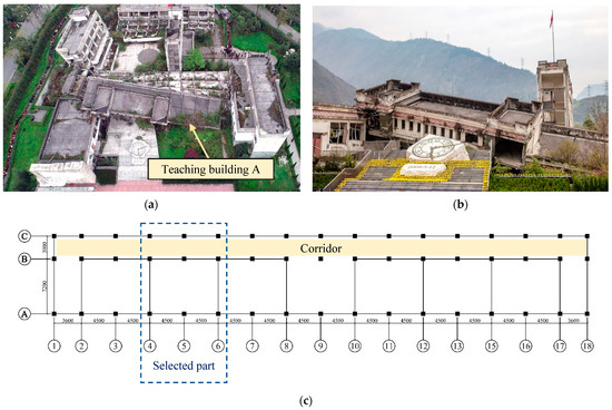
Figure 1.
The teaching building A of Xuankou Middle School after earthquake (quoted from Visual China Group). (a) Scene of Xuankou middle school after earthquake. (b) The collapsed teaching building A. (c) The layout of the structure (unit: mm).
In consideration of the size and load-bearing limitations of the shaking table, only the two-span of the teaching building from the first floor to the third floor were selected for simulation, and a shaking table test model, the height of whose single floor is 900 mm, was therefore designed with a scale of 1/4. In the model, there were 9 frame columns each with a clear height of 850 mm, and the size of each column was 60 × 60 mm; 4 galvanized iron wires with a diameter of 4 mm were configured as stressed steel bars, and the iron wires were scored so as to simulate the mechanical performance of ribbed steel bars. The stirrup was simulated by iron wires with a diameter of 2 mm and a spacing of 50 mm.
For the purpose of truly simulating the interaction between the infilled wall and the frame column, a full-brick infilled wall was arranged transversely and two half-height continuous infilled walls with a height of 405 mm were arranged longitudinally in line with the original construction drawings. According to the actual constructional details, a reinforced concrete coping of 20 mm was also set on the upper part of the infilled walls with a window opening. The infilled walls of the model were built with small grouting blocks, and two constructional columns were set in the transverse wall to ensure its integrity, and a pair of tie bars with a diameter of 2 mm was set every three blocks (150 mm) in the wall and is extended into the constructional columns and frame columns to ensure the effective connection of the wall and the column. Since the mechanical behaviour and damage patterns of frame columns during earthquakes were mainly observed in this test, frame beams were therefore not installed. Figure 2 shows the model construction drawing, internal arrangement and model appearance.
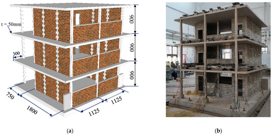
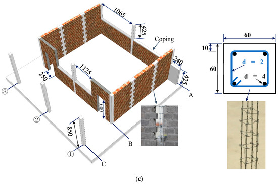
Figure 2.
The structural information of model. (a) Measurements of model (unit: mm). (b) Photo of model. (c) The structural arrangement and reinforcement of each column (unit: mm).
In addition, considering that the position of the middle span of the structure was simulated in this test, a low RC wall with the same height as that of the half-height continuous infilled wall was set beside the side column of the window opening in order to ensure that the side column at the bottom of the model could still be subjected to the restriction of the longitudinal half-height continuous infilled walls.
2.2. The Similarity Ratio
The law of similarity must be followed when a mechanical test is conducted by replacing the prototype structure with a scaled model [43]. The artificial mass model was selected as a similar model for this test that could simultaneously satisfy the simulation of the effects of both gravity and mass inertia. Table 1 indicates the similarity relationship of this test model.

Table 1.
The similarity ratio of the model.
2.3. Properties of Materials
The size of prototype columns is 350 × 350, and its concrete grade is C30. The reinforcement type of stress steel bar in columns is HRB335 and the stirrup is HPB235. The infilled walls are built by using of hollow blocks. The thickness of walls is 200 mm.
The model is made of fine-grained concrete, which is made of cement, sand and gravel in a ratio of 1:2.6:4.0. Before the experiment, the compressive strength of the fine-grained concrete cube was measured by the standard test, the value of which is 20.63 MPa. Due to the scaled frame column being of a smaller size, common standard steel bars cannot meet the reinforcement ratio requirements of its columns. Therefore, the galvanized iron wire was used as the stress steel bar of the frame column in this test. Before the experiment, a tensile test was carried out using the MTS to measure the tensile strength of the galvanized iron wire, and the observed value was 314 MPa.
2.4. Test System
The size of shaking table is 3.0 m × 3.0 m, of which the maximum bearing weight is 20 t. Its shaking frequency is from 0.4 Hz to 80 Hz. It can vibrate in both horizontal directions at the same time. The limit value of displacement is ±20 cm, the speed is 80 cm/s and the horizontal acceleration is 2.0 g when the table is fully loaded vertically.
The acceleration sensors were 941B produced by the IEM in China. It is equipped with four gears of acceleration, small speed, medium speed and large speed. The maximum value of acceleration that can be measured is 2.0 g. Strain gauges were BQ120-60AA, which are special use for concrete. The arrangement scheme of all sensors was different in each test, which can be seen in Section 3.
3. Results and Discussion
3.1. Modal Tests
3.1.1. Natural Frequency
Pulsation refers to the response of the structure under environmental excitations. Generally speaking, the pulsation signal is relatively weak and is susceptible to noise pollution. In this experiment, a high-quality pulsation signal was obtained by carefully selecting sensors, data collectors and properly using the multi-segment averaging method [44].
In order to analyse the differences in natural frequency with and without the infilled wall, pulsation tests was carried out on the structure at different stages (before and after the infilled wall was built, respectively). As shown in Figure 3a and Figure 4a, a set of acceleration sensors (CH1 and CH2) were arranged transversely and longitudinally, respectively, along the structure at the centre point of the top layer of the model for obtaining the transverse and longitudinal fundamental frequencies of the structure, and a pair of acceleration sensors (CH3 and CH4) were arranged on both sides of the top floor to obtain the torsion frequency of the structure.
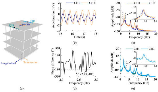
Figure 3.
Microseism tests of RC structure without infilled walls. (a) Sensor location. (b) Time history. (c) Auto-power spectrum. (d) Phase spectrum difference of CH3 and CH4. (e) Auto-power spectrum.
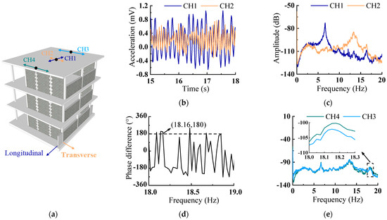
Figure 4.
Microseism tests of RC structure with infilled walls. (a) Sensor location. (b) Time history. (c) Auto-power spectrum. (d) Phase spectrum difference of CH3 and CH4. (e) Auto-power spectrum.
Figure 3b,c show, respectively, the acceleration time history and the auto-power spectrum obtained by the sensor at the centre of the top layer before the wall was built. (Without consideration of the acceleration, the unit will not be converted temporarily, and the coordinate of the time history is indicated by the voltage value in mV.) It can be seen from the above figures that the longitudinal natural frequencies of the first and second modes of the model are 1.88 Hz and 5.58 Hz, respectively, while the transverse ones are 1.90 Hz and 5.72 Hz, respectively. At this time, the longitudinal or transverse lateral stiffness of the structure is only provided by frame columns with equal sections as the model is not built with infilled walls. Hence, the natural frequencies in two directions are relatively close.
Figure 3e represents the auto-power spectrum, which shows that the torsion frequency of the model is about 2.73 Hz, obtained by two acceleration sensors in the same direction at the edge of the top layer. It can be concluded from the Fourier phase difference curve of the two acceleration signals (CH3 and CH4) shown in Figure 3d that the phase difference at the frequency 2.73 Hz is −180°, indicating that the value of the torsion frequency identified in the auto-power spectrum is credible.
Figure 4 shows the natural frequency with the walls laid. The time history at the centre of the top layer of the model is shown in Figure 4b, and its corresponding auto-power spectrum is shown in Figure 4c. It can be seen that the values of longitudinal and transverse fundamental frequency increase to 6.65 Hz and 13.40 Hz, respectively, after the infilled walls are built. Obviously, this can be attributed to the full-brick infilled wall in the transverse direction. Although an infilled wall is also installed in the longitudinal direction, door and window openings with a large area (see Figure 2) were opened, leading to the weakening of the longitudinal lateral stiffness and a lower longitudinal fundamental frequency, which is only about a half of the transverse fundamental frequency. Figure 4e demonstrates not only the same transverse fundamental frequency as that obtained by the centre sensor, but also the torsion frequency of the model, which is 18.16 Hz. Figure 4d further proves the reliability of the obtained torsion frequency from the phase difference. The torsion frequency increased by 6.65 times compared with that when the wall is not built. Such a large increase in torsion frequency is caused by the constraint of the transverse full-brick infilled wall on the model torsion. Figure 5 displays the comparison of the fundamental frequency and torsion frequency of the model with and without infill walls. It also shows that once the infilled walls are built, the overall stiffness of the frame is improved and the natural frequency is significantly improved. In particular, the stiffness of the transverse infilled wall is very large, which will restrain the transverse deformation and the torsion of the structure to a certain extent; the transverse and torsional frequency increase more than the longitudinal one.
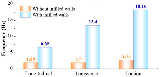
Figure 5.
Comparison of structure frequency with or without infilled walls.
3.1.2. Damping Ratio
In general, the impulse response of the structure can be obtained by percussion. As shown in Figure 6, the specific method is as follows: tap the top floor with square timbers, and obtain the longitudinal and transverse impulse response of the structure through the acceleration sensor arranged at the centre of the top floor. The sensor layout scheme used in the percussion test is the same as that shown in Figure 3a and Figure 4a.
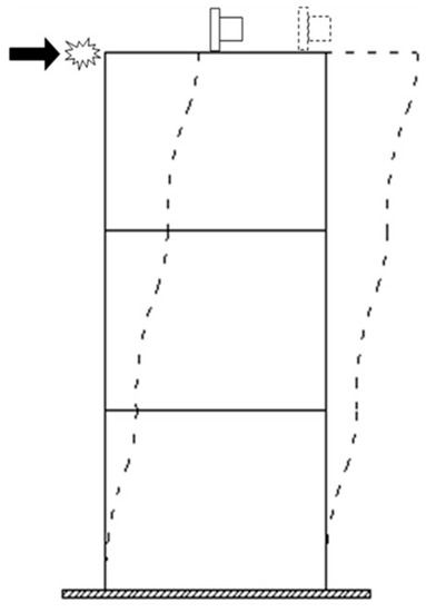
Figure 6.
Percussion test.
The impulse response before the infilled wall is built obtained by tapping the top floor longitudinally and transversely along the model is shown in Figure 7. It shows that the longitudinal and transverse fundamental frequency of the structure are basically equal, which is consistent with the conclusion drawn from the previous pulsation test. Simultaneously, the attenuation speeds of the longitudinal and transverse acceleration are only slightly different, which illustrates that the damping ratios of the structure in two directions are also relatively close. According to Equation (1), where over j cycles the motion decreases from Ai to Ai+j, the longitudinal and transverse damping ratios of the structure are 1.05% and 1.33%, respectively.
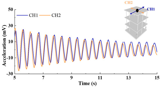
Figure 7.
Attenuation curve of acceleration of frame without infilled walls.
After the infilled wall was built in the model, the same percussion test was carried out on the structure. Figure 8 shows the obtained longitudinal and transverse response. Obviously, the frequency of the structure in the transverse direction is almost twice that in the longitudinal direction according to the time history, which is also highly consistent with the result of the pulsation test. Meanwhile, the attenuation speed of the transverse acceleration is significantly higher than that of the longitudinal one, indicating that the transverse damping ratio of the structure is much larger than that of the longitudinal one after the infill wall is built. Calculated in accordance with Formula (1), the longitudinal and transverse damping ratios are 1.61% and 3.26%, respectively. Figure 9 shows that the damping ratio increases due to the friction between the infilled wall and the frame column or inside the infilled wall. Furthermore, the frictional energy consumption caused by slight deformation is high because of the full-brick infilled wall in the transverse direction. Therefore, the damping ratio is much larger than the longitudinal one.
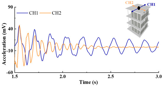
Figure 8.
Attenuation curve of acceleration of frame with infilled walls.
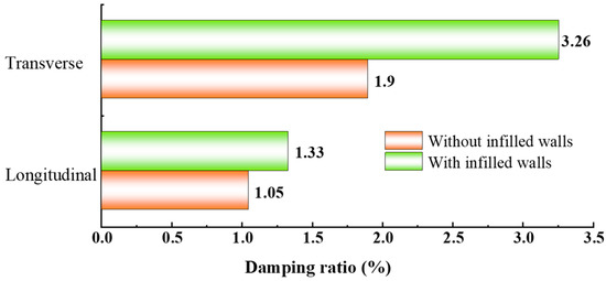
Figure 9.
Comparison of structure damping ratio with or without infilled walls.
3.2. Structural Response in Percussion Test
3.2.1. Reliability of Strain
Before the percussion test, multi-channel strain sensors were placed on the frame column of the bottom layer of the model. After tapping the top of the model longitudinally, various strain signals were obtained.
In order to verify the reliability of the strain, multiple strains were arranged at the upper and lower ends of each column. Figure 10 is the strain time history comparison of the upper and lower ends of the column C2 at the bottom layer. This shows that the amplitude and phase of each strain measuring point on the same column behaves normally, which satisfies the deformation characteristics of the frame column, as shown in Figure 11. Specifically, strains on the contralateral side are the same in value but opposite in direction, while strains on the diagonal line are the same both in value and phase. The strain of other columns also possesses such characteristics under careful inspection.
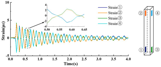
Figure 10.
Comparison of strain obtained from one column.
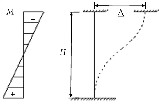
Figure 11.
Deformation characteristics of bottom columns.
3.2.2. Internal Force Distribution of Columns
Most of the structural damages of the building start with the failure of the bottom column during an earthquake. Consequently, this test focuses on the impact of the infilled wall on the seismic performance of the bottom column. Figure 12a illustrates the strain t of the upper end of each column on the bottom floor when the top floor slab is struck longitudinally, and the peak strain of each column at t = 0.42 s is selected and marked on the schematic diagram shown in Figure 12b. It can be seen that the strains at the end of the columns (A1, A2, A3, B2) constrained by the longitudinal half-height continuous infilled wall are all within 6 to 8με, while those at the end of the unconstrained columns (C1, C2, and C3) are only within 2 to 3με, which indicates that the strain at the end of the column constrained by the longitudinal half-height continuous infilled wall is 2 to 4 times that of the unconstrained column for the reason that the column between windows is constrained by the half-height continuous infill wall, and its effective height shortens while stiffness increases, as shown in Figure 12e.
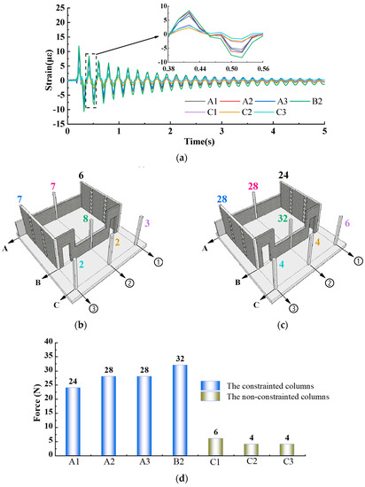
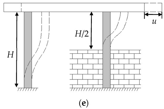
Figure 12.
Comparison of strain, internal force distribution and deformation pattern of columns in different constraint condition. (a) Time history of strain on top of columns. (b) Strain of bottom columns at t = 0.42 s (unit: με). (c) Shear force of bottom columns at t = 0.42 s (unit: N). (d) The internal forces distribution of bottom columns at t = 0.42 s. (e) Deformation pattern of columns with or without infilled walls.
When the structure does not undergo torsion and only translates along the longitudinal direction, the shear force is distributed according to the stiffness and then highly concentrated on the restrained column, making it easier to form a plastic hinge. Additionally, the internal force distribution between the frame columns at the bottom is then obtained from Equation (2), as shown in Figure 12c,d. It can be found that the shear forces of the columns (A1, A2, A3, B2) constrained by the longitudinal half-height continuous infilled wall reach 24 to 32N, respectively, while those of the unconstrained columns (C1, C2, C3) are only 4 to 6N, which shows that the shear force of the constrained column is 4 to 8 times that of the unconstrained column under the same lateral displacement.
where F refers to the shear force at the end of the column;
ε denotes the strain at the end of the column, which is determined according to Figure 12b;
W represents the bending of the frame column (where b and h are equally valued at 60 mm);
E indicates the elastic modulus of concrete, which is valued in consistence with concrete C20 to be 2.55 × 10⁴ MPa;
H expresses the effective free height of the column. Values for the constrained and unconstrained columns are set as 425 mm and 850 mm, respectively.
3.3. Structural Seismic Test
3.3.1. Seismic Input
Considering that the structural deformation caused by the percussion test is very slight, an earthquake simulation experiment is conducted for the model placed on a shaking table in order to further determine the mechanical behaviour of the bottom columns under the actual earthquake.
Combined with previous experimental results, the initially input target peak acceleration is set as 0.3 g. All the sensors can work normally, and structural damage is not obvious. This is used to focus on the response of the structure in the elastic phase and more intensively focus on the strain of the bottom column.
Figure 13 demonstrates the acceleration time history, the original record of which can date back to the Wolong seismic wave of the Wenchuan earthquake, obtained by the longitudinal and transverse sensors deployed on the platform. The figure shows that the longitudinal and transverse peak accelerations of the platform are 0.28 g and 0.32 g, respectively.
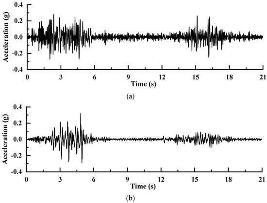
Figure 13.
The acceleration of the shaking table. (a) Longitudinal. (b) Transverse.
3.3.2. Displacement of Bottom Floor
For the purpose of observing whether the torsion of the structure occurs under bidirectional seismic inputs, a set of high-precision displacement sensors (Disp. A and Disp. C) are placed on the bottom floor of the structure. If torsion occurs, the signal will then show the characteristics of the opposite phase.
Figure 14 shows that the signals obtained by the two longitudinally arranged sensors are completely coincident with equal magnitude and the same phase, which indicates that the structure only translates in the longitudinal direction without torsion under the action of a bidirectional earthquake, satisfying the prerequisite of the seismic shear force distributed by the lateral stiffness of the members.
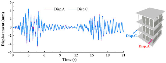
Figure 14.
Comparison of displacement of axis A and C in earthquake.
3.3.3. Strain of the Bottom Column
Under the bidirectional seismic inputs, the strain of the bottom column is obtained. The strain shown in Figure 15a is selected for analysis to verify whether conclusions obtained from the percussion pulse excitation are consistent with the internal force distribution under the earthquake. The figure exhibits that the peak strain of each column at the initial moment of the earthquake does not exceed 100 με, which does not reach the ultimate tensile strain of concrete, indicating that the structure is still in the elastic stage and the applicable conditions of Equation (2) are satisfied. Therefore, the law of internal force distribution among columns at the bottom under earthquake conditions can then be derived.
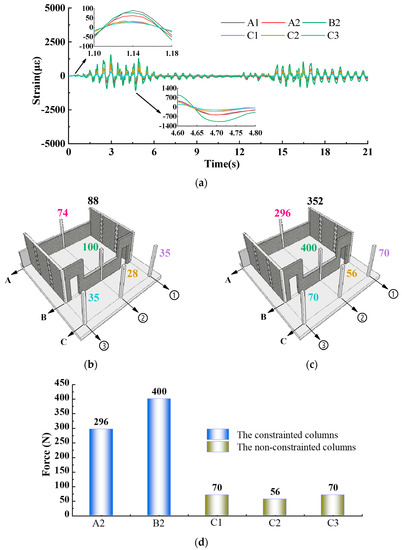
Figure 15.
Comparison on strain and internal force distribution of columns in different constraint condition in earthquake conditions. (a) Time history of strain on top of columns in earthquake. (b) Strain of bottom columns at t = 1.14 s (unit: με). (c) Shear force of bottom columns at t = 1.14 s (unit: N). (d) The internal forces distribution of bottom columns at t = 1.14 s.
The strain of the upper section of each column in Figure 15a is marked in Figure 15b; then, the schematic diagram of the internal force distribution can be calculated according to Formula (2), as shown in Figure 15c. (The strain gauge at the end of column A3 does not work normally, so its relevant information is not marked in the diagram). It can be seen that the strains of the columns (A1, A2, and B2) constrained by the longitudinal half-height continuous infilled wall reach 74 to 100 με, respectively, with corresponding transverse shear forces of 296 to 400N, while those of the unconstrained columns (C1, C2, and C3) are only 28 to 35 με, respectively, with seismic shear forces of 56 to 70N. Apparently, as is shown in Figure 15d, the conclusions drawn from the bottom column of the structure under the seismic action and the percussion pulse excitation are highly consistent; namely, the strain of the bottom column constrained by the half-height continuous infill wall is 2 to 4 times that of the unconstrained one, while the seismic shear force assigned to the former is 4 to 8 times that assigned to the latter.
It can thus be seen that the infilled wall regarded as a non-structural component has a significant impact on the anti-seismic capacity of the structure. In particular, the improperly set half-height continuous infilled wall will result in high cohesion of the internal force of columns between windows, which will get broken first and then lose their vertical load-bearing capacity.
3.3.4. Structural Damage and Collapse
Under an input of about 0.3 g, there is no damage to the frame except for small cracks in the opening and filling wall. Therefore, the inputted peak acceleration is adjusted to 1.0 g and the shaking table test is then carried out so as to focus on the mode of destruction at the critical collapse moment of the bottom column of the frame.
Figure 16 shows the destruction of the structure near the collapse. As can be seen from the figure, the damage occurs mainly on components of the bottom layer instead of the second and above ones since the vertical load and seismic shear force of components of the bottom layer are both greater than those of the upper layers. The transverse full-brick infill wall has a large lateral stiffness, which restrains the transverse deformation of the structure under the earthquake and causes a severe shear failure to occur when experiencing a large earthquake.
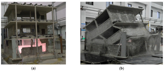
Figure 16.
The restrained column takes the lead in bearing failure, resulting in collapse of the structure. (a) The restrained columns are seriously damaged. (b) The structure collapses.
In addition, there are damages of different degrees shown at the ends of the bottom columns. In particular, such damages often occur in the window column constrained by the half-height continuous infilled wall before the corridor column. Generally speaking, the shear span ratio can reflect the difficulty of the shear failure of the structure to a certain extent. Even if the window column is constrained by the half-height continuous infill wall, its shear span ratio by calculation is 3.5 (λ > 2), which indicates that it is still a long column, and its damage pattern is curved, which is consistent with the experimental results.
Compared with previous studies, this model is a multi-storey and multi-span reinforced concrete frame with infilled wall, rather than frame with non-infilled walls or plane wall-frame. In particular, various forms of infilled walls are set along the longitudinal and transverse directions of the structure, such as the continuous half-height infilled walls under the window, the infilled walls with the door openings and small window openings, and the transverse full infilled walls. They can improve the overall stiffness and damping ratio of the structure, and the full infilled walls have a more significant effect on restraining the torsion of the structure. The shaking table test is carried out to study the internal force distribution of bottom columns in elastic and the damage of members in plastic. It is seldom seen that the ground motion is raised to 1.0 g in the experiment, which was equivalent to the earthquake suffered by the prototype structure in the Wenchuan earthquake, creating the input record of the shaking table test. Finally, the collapse characteristic of the model is consistent with the actual earthquake damage, which proves that the continuous half-height infilled walls under the window lead to the high concentration of seismic shear force on the constrained columns in the RC frame with eccentrically placed open corridors, and takes the lead in structure collapse.
4. Conclusions
In order to discuss the influences of infilled walls on the seismic performance of an RC frame, a set of scaled models of a frame with eccentrically placed open corridors with a scale of 1 to 4 are made in this paper. According to the analyses of the acceleration and strain of the models under the pulsation test and the percussion test, together with the implementation of the shaking table test, the following conclusions can be drawn:
- (1)
- After the infilled wall is installed in the frame, its natural frequency and damping ratio increase significantly.
- (2)
- The form of the infilled wall has a great influence on the lateral stiffness of the structure. The transverse walls in the teaching buildings generally do not have openings, while the longitudinal walls are often provided with doors and windows. Such kinds of spatial arrangements lead to a much greater lateral stiffness in the transverse direction than in the longitudinal direction of this type of structure. Specifically, the transverse fundamental frequency of the frame structure with the infilled wall is about twice that of the vertical one.
- (3)
- When analysing the force and deformation of the frame, its effect of the space with longitudinal and transverse infilled walls should be considered. In general, the stiffness of the transverse infilled wall is very large, which will restrain the transverse deformation of the structure to a certain extent and finally present a deformation translating longitudinally during an earthquake.
- (4)
- At present, the frame with eccentrically placed open corridors, which has “inherent” seismic defects, is mostly adopted in school teaching buildings. The columns with lateral stiffness of a big difference along the longitudinal axis of the structure, especially those constrained by the longitudinal half-height continuous infilled wall, firstly form plastic hinges and lose load-bearing capacity, further resulting in the collapse of the structure.
As a result, the impact of infilled walls on the seismic performance of the structure should be inevitably considered in the seismic design. Additionally, infilled walls should be arranged scientifically and reasonably to weaken their restraints on the columns, ensure a uniform distribution of the internal force between columns and avoid structural collapse caused by the failure of some critical components.
In the future, the shaking table test will be carried out on the model with larger similarity, so as to make the material properties, especially the reinforcement, meet the actual ones. In addition, based on the results, comparative experiments need to be carried out to explore whether the longitudinal lateral stiffness of each axis can be balanced by optimizing the layout of infilled walls, and the seismic shear will not be highly concentrated on some columns. It also can be verified that the restraint effects of walls on frame columns will be improved by using infilled walls with low elastic modulus and high ductility.
Author Contributions
Conceptualization, B.W. and X.G.; experiment, B.W., X.G., Y.X. and X.-Q.F.; validation, B.W. and X.G.; investigation, B.W. and X.G.; data curation, B.W., Y.X., X.-Q.F. and B.C.; writing—original draft preparation, B.W. and Y.X.; writing—review and editing, B.W. and X.G. All authors have read and agreed to the published version of the manuscript.
Funding
This research was funded by Science for Earthquake Resilience, grant number XH22022YA; Science and Technology Project of Hebei Education Department, grant number BJK2022066; and Fundamental Research Funds for the Central Universities, grant number ZY20215109.
Institutional Review Board Statement
Not applicable.
Informed Consent Statement
Not applicable.
Data Availability Statement
Not applicable.
Conflicts of Interest
The authors declare no conflict of interest.
References
- Li, H.-N.; Xiao, S.-Y.; Huo, L.-S. Damage investigation and analysis of engineering structures in the Wenchuan earthquake. J. Build. Struct. 2008, 29, 10–19. [Google Scholar]
- Guo, X. Characteristics and mechanism analysis of the great Wenchuan earthquake. Earthq. Eng. Eng. Dyn. 2009, 29, 74–87. [Google Scholar]
- Yang, W.-S.; Guo, X.; Xu, W.-X.; Yuan, X. Seismic behaviours of RC frames retrofitted with wing walls. J. Vib. Shock 2015, 34, 144–152. [Google Scholar]
- Tan, H.; Li, J.; Zhang, D.-J.; Zhang, Z.-Q. Earthquake damage investigation on red flag primary school buildings in yushu autonomous prefecture. World Earthq. Eng. 2011, 27, 96–101. [Google Scholar]
- Kishiki, S.; Yamada, S.; Matsumoto, Y.; Asada, H.; Koyama, T.; Shimada, Y. Damage to column bases and roof joints in steel school buildings due to the 2011 Tohoku earthquake. AIJ J. Technol. Des. 2013, 19, 585–590. [Google Scholar] [CrossRef][Green Version]
- Li, J.-W.; Bo, J.-S.; Lu, T.; Cai, X.-G.; Zhang, J.-Y. Seismic damage analysis of school buildings in Yushu Ms 7.1 earthquake. J. Nat. Disasters 2013, 22, 123–129. [Google Scholar]
- Sun, B.-T.; Zhou, Q.; Yang, Y.-C. Seismic fortification objects of rural primary and middle schools: The damage cause study for primary and middle school buildings of Leigu town, Beichuan county in Wenchuan earthquake. J. Earthq. Eng. Eng. Vib. 2011, 31, 1–10. [Google Scholar]
- Bal, İ.-E.; Smyrou, E. Simulation of the earthquake-induced collapse of a school building in Turkey in 2011 Van Earthquake. Bull. Earthq. Eng. 2016, 14, 3509–3528. [Google Scholar] [CrossRef]
- Bo, J.-S.; Li, X.-B.; Duan, Y.-S.; Su, Z.-D. Investigation and analysis of seismic damage to school buildings in m_s7.0 Jiuzhaigou earthquake. Earthq. Eng. Eng. Dyn. 2018, 38, 120–128. [Google Scholar]
- Giordano, N.; Luca, F.-D.; Sextos, A. Analytical fragility curves for masonry school building portfolios in Nepal. Bull. Earthq. Eng. 2021, 19, 1121–1150. [Google Scholar]
- Ruggieri, S.; Porco, F.; Uva, G.; Vamvatsikos, D. Two frugal options to assess class fragility and seismic safety for low-rise reinforced concrete school buildings in southern Italy. Bull. Earthq. Eng. 2021, 19, 1415–1439. [Google Scholar] [CrossRef]
- Zhai, C.-H.; Wang, X.-M.; Kong, J.-C.; Wei, Y.-L.; Jin, W.; Zhao, Y. Progress and prospect of seismic performance of masonry-infilled RC frames. J. Harbin Inst. Technol. 2018, 50, 1–13. [Google Scholar]
- Zhang, W.-X.; Pang, B.; Xu, S. Research on bottom column end moment amplification factor of RC frame based on incremental dynamic analysis and fragility analysis. J. Chongqing Univ. 2019, 42, 37–45. [Google Scholar]
- Noh, N.M.; Liberatore, L.; Mollaioli, F.; Tesfamariam, S. Modelling of masonry infilled RC frames subjected to cyclic loads: State of the art review and modelling with Open Sees. Eng. Struct. 2017, 150, 599–621. [Google Scholar]
- Jin, H.-G.; Li, H.-J.; Sun, G.-J. Analysis of interaction between reinforced concrete frame and infilled wall subject to earthquake-induced ground motion. Earthq. Eng. Eng. Dyn. 2017, 37, 31–41. [Google Scholar]
- Ruggieri, S.; Fiore, A.; Uva, G. A new approach to predict the fundamental period of vibration for newly-designed reinforced concrete buildings. J. Earthq. Eng. 2021, 1–26. [Google Scholar] [CrossRef]
- Chakra-Varthy, P.; Basu, D. Natural period and vertical distribution of base shear in confined masonry buildings using ambient vibration test. Bull. Earthq. Eng. 2021, 19, 1851–1899. [Google Scholar] [CrossRef]
- Yousefianmoghadam, S.; Behmanesh, I.; Stavridis, A.; Moaveni, B.; Nozari, A.; Sacco, A. System identification and modelling of a dynamically tested and gradually damaged 10-story reinforced concrete building. Earthq. Eng. Struct. Dyn. 2018, 47, 25–47. [Google Scholar] [CrossRef]
- Furtado, A.; De Risi, M.T. Recent findings and open Issues concerning the seismic behaviour of masonry infill walls in RC buildings. Adv. Civ. Eng. 2020, 2020, 9261716. [Google Scholar] [CrossRef]
- Shan, S.; Li, S. Progressive collapse mechanisms of post-tensioned reinforced concrete frames considering effect of infill walls. Eng. Struct. 2022, 250, 1–16. [Google Scholar] [CrossRef]
- Singh, B.; Ramesh, K.-V.; Sudheer, G.; Ramesh, C.-R. Comparison of reinforced concrete frames modelled with and without infill walls. Int. J. Civ. Eng. Technol. 2017, 8, 1636–1644. [Google Scholar]
- Işık, E.; Aydın, M.-C.; Ulu, A.-E. Comparison of infill wall effects in reinforced-concrete frames over different parameters. Adv. Eng. Sci. 2022, 2, 80–86. [Google Scholar]
- Jahangir, H.; Esfahani, M.-R. Bond behaviour investigation between steel reinforced grout composites and masonry substrate. Iran. J. Sci. Technol. 2022, 1–17. [Google Scholar] [CrossRef]
- Benavent-Climent, A.; Ramírez-Márquez, A.; Pujol, S. Seismic strengthening of low-rise reinforced concrete frame structures with masonry infill walls: Shaking-table test. Eng. Struct. 2018, 165, 142–151. [Google Scholar] [CrossRef]
- Guljaš, I.; Penava, D.; Laughery, L.; Pujol, S. Dynamic tests of a large-scale three-story RC structure with masonry infill walls. J. Earthq. Eng. 2018, 24, 1675–1703. [Google Scholar] [CrossRef]
- Lourenço, P.-B.; Leite, J.-M.; Paulo-Pereira, M.-F.; Campos-Costa, A.; Candeias, P.-X.; Mendes, N. Shaking table testing for masonry infill walls: Unreinforced versus reinforced solutions. Earthq. Eng. Struct. Dyn. 2016, 45, 2241–2260. [Google Scholar] [CrossRef]
- Hashemi, A.; Mosalam, K.-M. Shake-table experiment on reinforced concrete structure containing masonry infill wall. Earthq. Eng. Struct. Dyn. 2006, 35, 1827–1852. [Google Scholar] [CrossRef]
- Binici, B.; Canbay, E.; Aldemir, A.; Demirel, I.-O.; Uzgan, U.; Eryurtlu, Z.; Bulbul, K.; Yakut, A. Seismic behaviour and improvement of autoclaved aerated concrete infill walls. Eng. Struct. 2019, 193, 68–81. [Google Scholar] [CrossRef]
- Papatheocharis, T.; Perdikaris, P.-C.; Moretti, M.-L. Response of RC frames strengthened by RC infill walls: Experimental study. J. Struct. Eng. 2019, 11, 04019129. [Google Scholar] [CrossRef]
- Sanada, Y.; Maidiawati. Modelling of interactions between RC columns and masonry infill in buildings with a column-sway mechanism. Jpn. Archit. Rev. 2018, 1, 109–117. [Google Scholar] [CrossRef]
- Onat, O.; Correia, A.-A.; Lourenço, P.-B.; Koçak, A. Assessment of the combined in-plane and out-of-plane behaviour of brick infill walls within reinforced concrete frames under seismic loading. Earthq. Eng. Struct. Dyn. 2018, 47, 2821–2839. [Google Scholar] [CrossRef]
- Dautaj, A.-D.; Kadiri, Q.; Kabashi, N. Experimental study on the contribution of masonry infill in the behaviour of RC frame under seismic loading. Eng. Struct. 2018, 165, 27–37. [Google Scholar] [CrossRef]
- Basha, S.-H.; Kaushik, H.-B. Behavior and failure mechanisms of masonry-infilled RC frames (in low-rise buildings) subject to lateral loading. Eng. Struct. 2016, 111, 233–245. [Google Scholar] [CrossRef]
- Brodsky, A.; Rabinovitch, O.; Yankelevsky, D.Z. Determination of the interaction between a masonry wall and a confining frame. Eng. Struct. 2018, 167, 214–226. [Google Scholar] [CrossRef]
- Penava, D.; Sarhosis, V.; Kožar, I.; Guljaš, I. Contribution of RC columns and masonry wall to the shear resistance of masonry infilled RC frames containing different in size window and door openings. Eng. Struct. 2018, 172, 105–130. [Google Scholar] [CrossRef]
- Guo, Z.-X.; Huang, Q.-X.; Wei, R.-F.; Liu, Y. Experimental study of the seismic behaviour of irregularly brick infilled RC frames. China Civ. Eng. J. 2010, 43, 46–54. [Google Scholar]
- Peng, Q.-M.; Zhou, X.-J.; Yang, C.-H. Influence of connection and constructional details on masonry-infilled RC frames under cyclic loading. Soil Dyn. Earthq. Eng. 2018, 108, 96–110. [Google Scholar] [CrossRef]
- Baghi, H.; Oliveira, A.; Valença, J.; Cavaco, E.; Neves, L.; Júlio, E. Behaviour of reinforced concrete frame with masonry infill wall subjected to vertical load. Eng. Struct. 2018, 171, 476–487. [Google Scholar] [CrossRef]
- Razzaghi, M.S.; Javidnia, M. Evaluation of the effect of infill walls on seismic performance of RC dual frames. Int. J. Adv. Struct. Eng. 2015, 7, 49–54. [Google Scholar] [CrossRef]
- Ricci, P.; Domenico, M.-D.; Verderame, G.-M. Experimental assessment of the in-plane/out-of-plane interaction in unreinforced masonry infill walls. Eng. Struct. 2018, 173, 960–978. [Google Scholar] [CrossRef]
- Pantò, B.; Silva, L.; Vasconcelos, G.; Lourenço, P.-B. Macro-modelling approach for assessment of out-of-plane behaviour of brick masonry infill walls. Eng. Struct. 2019, 181, 529–549. [Google Scholar] [CrossRef]
- Al Hanoun, M.-H.; Abrahamczyk, L.; Schwarz, J. Macromodeling of in- and out-of-plane behaviour of unreinforced masonry infill walls. Bull. Earthq. Eng. 2019, 17, 519–535. [Google Scholar] [CrossRef]
- Zhang, M.-Z. Concept and Application of Earthquake Engineering; Seismological Press: Beijing, China, 2015; pp. 177–184. [Google Scholar]
- Guo, X. Collapse Mechanism of RC Frame Structures Suffered from Strong Earthquake; Architecture & Building Press: Beijing, China, 2018; pp. 20–21. [Google Scholar]
Publisher’s Note: MDPI stays neutral with regard to jurisdictional claims in published maps and institutional affiliations. |
© 2022 by the authors. Licensee MDPI, Basel, Switzerland. This article is an open access article distributed under the terms and conditions of the Creative Commons Attribution (CC BY) license (https://creativecommons.org/licenses/by/4.0/).