Modular Regulators of Water Level in Ditches of Subirrigation Systems
Abstract
1. Introduction
2. Materials and Methods
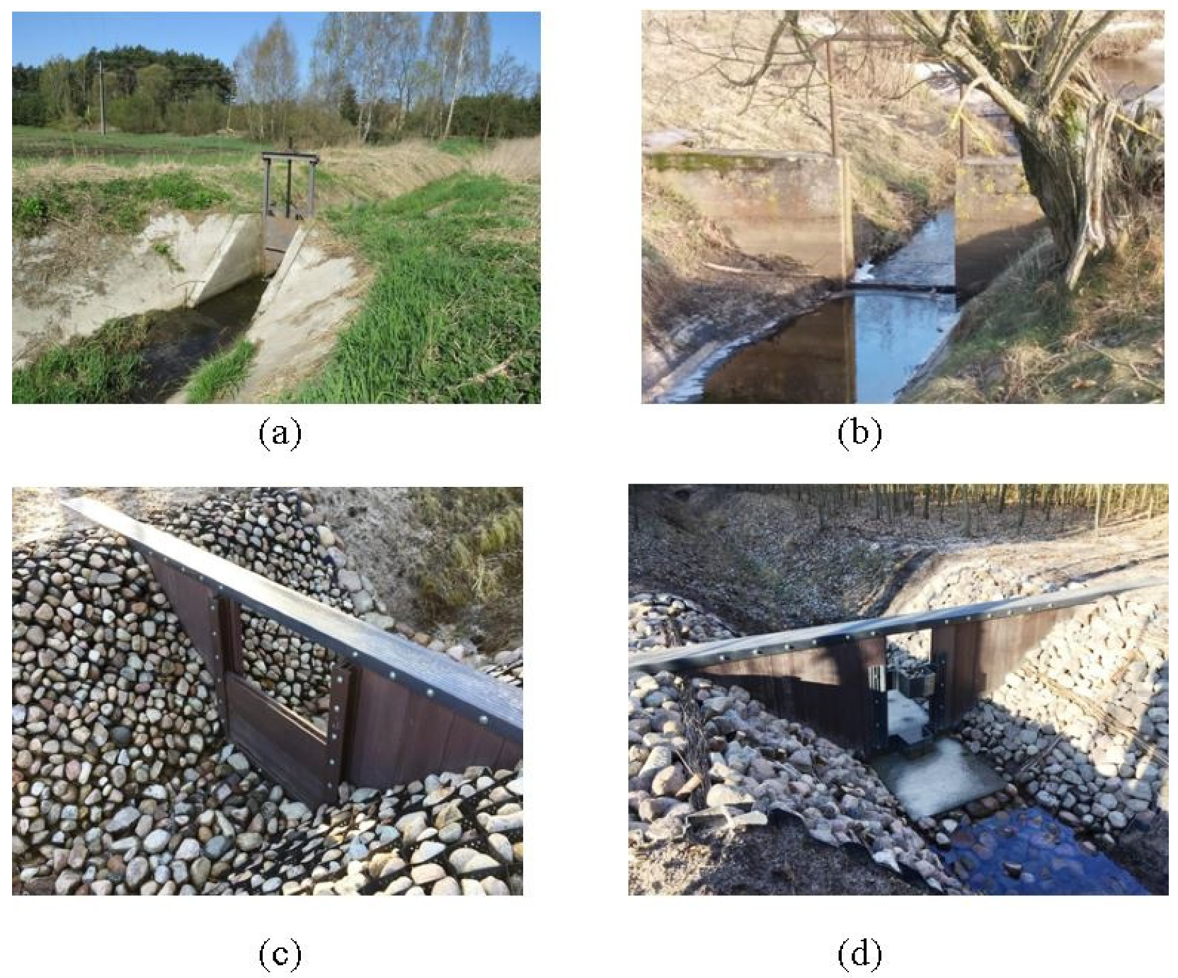
2.1. Regulators
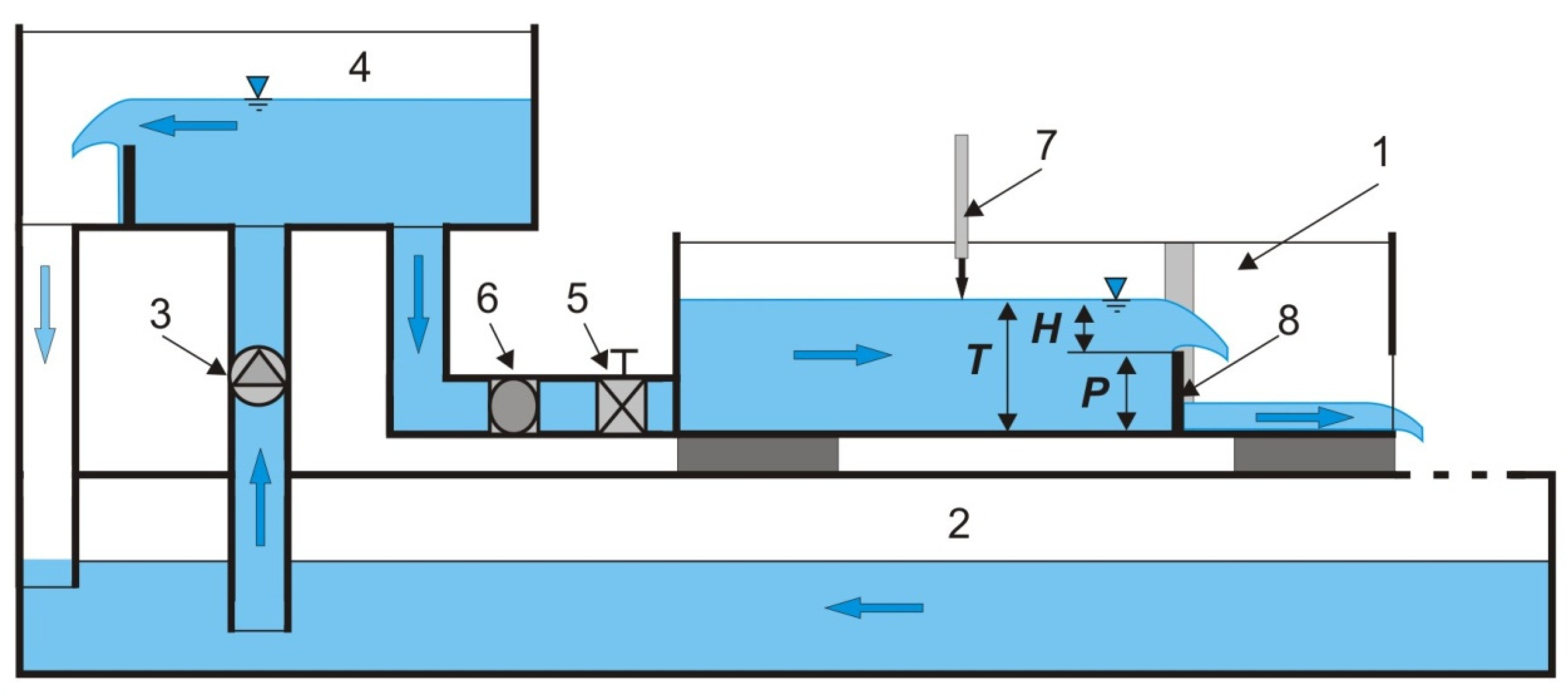
2.2. Laboratory Experiment
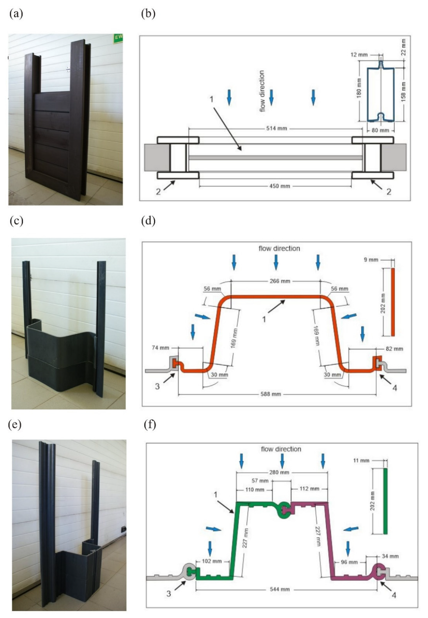
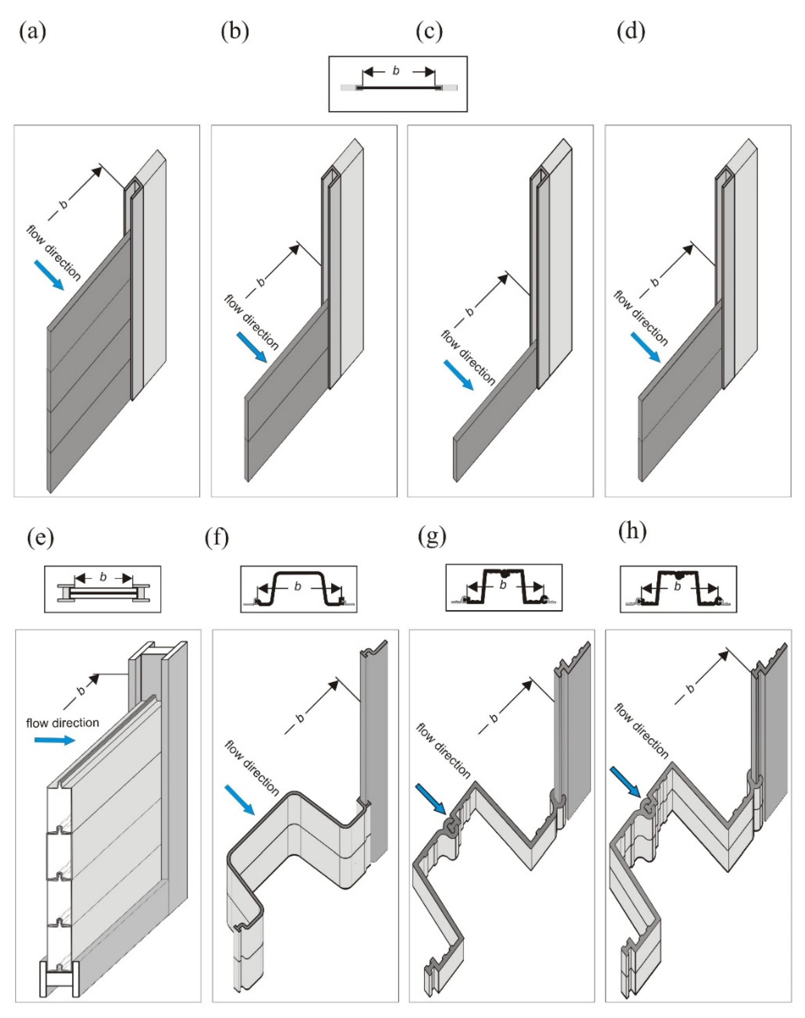
2.3. Study Models
3. Laboratory Test Results
3.1. Effective Flow Qe
- S model, the scope of formula validity 19.1 cm ≤ H ≤ 85.4 cm:
- U model, the scope of formula validity 20.0 cm ≤ H ≤ 89.2 cm:
- Z model, the scope of formula validity 21.0 cm ≤ H ≤ 105.0 cm:
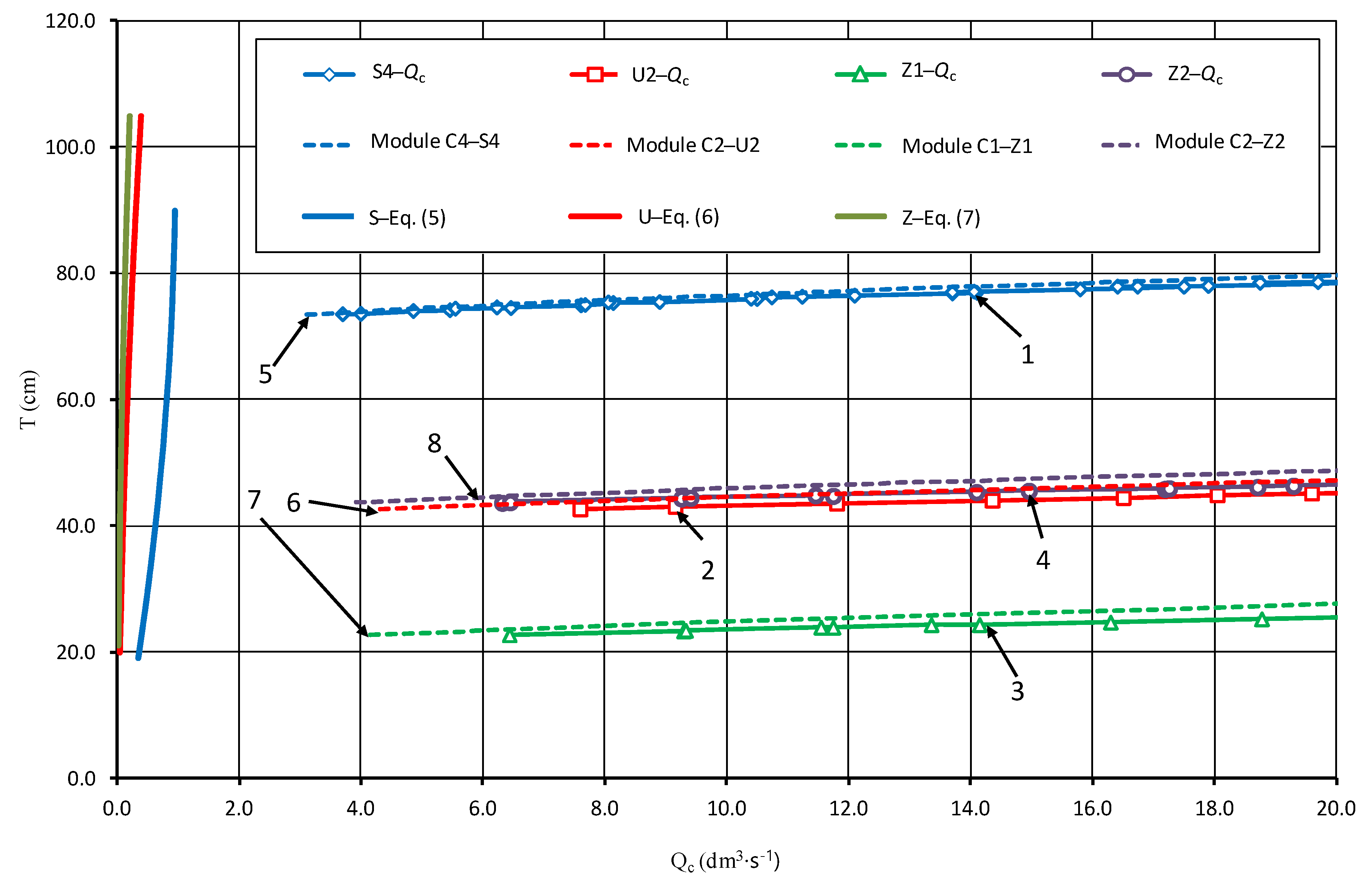
3.2. Total Flow Qc
4. Discussion
5. Conclusions
- The tested regulators are suitable for damming water in drainage ditches with flows equal to or greater than the effective flow. The S regulator with straight beams, which are mounted in side recesses without special locks, has the highest effective flow.
- The S rectilinear regulator is characterized by the lowest value of modular flow coefficient taking into account the shape of the overflow edge profile compared to other regulators.
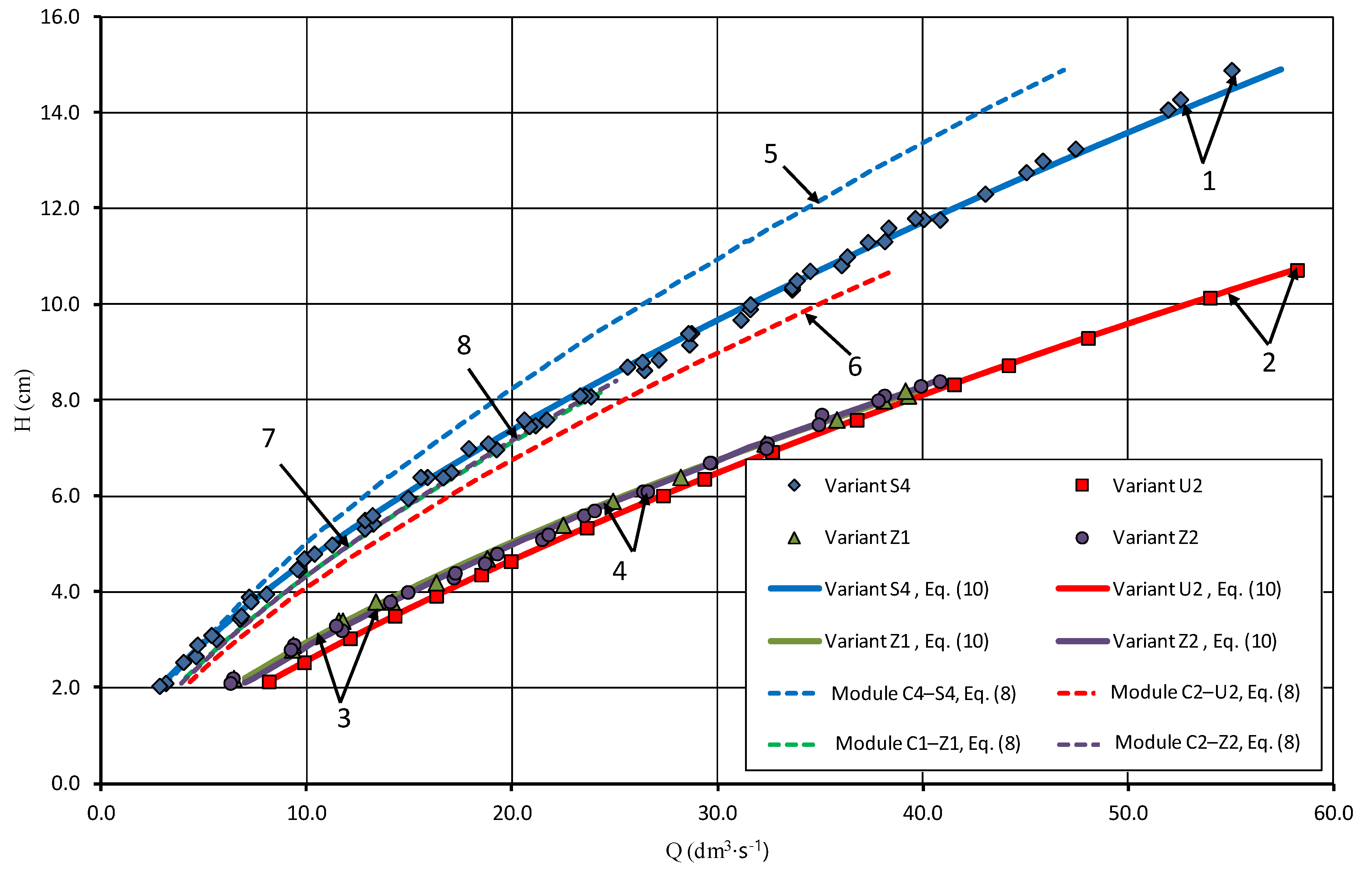
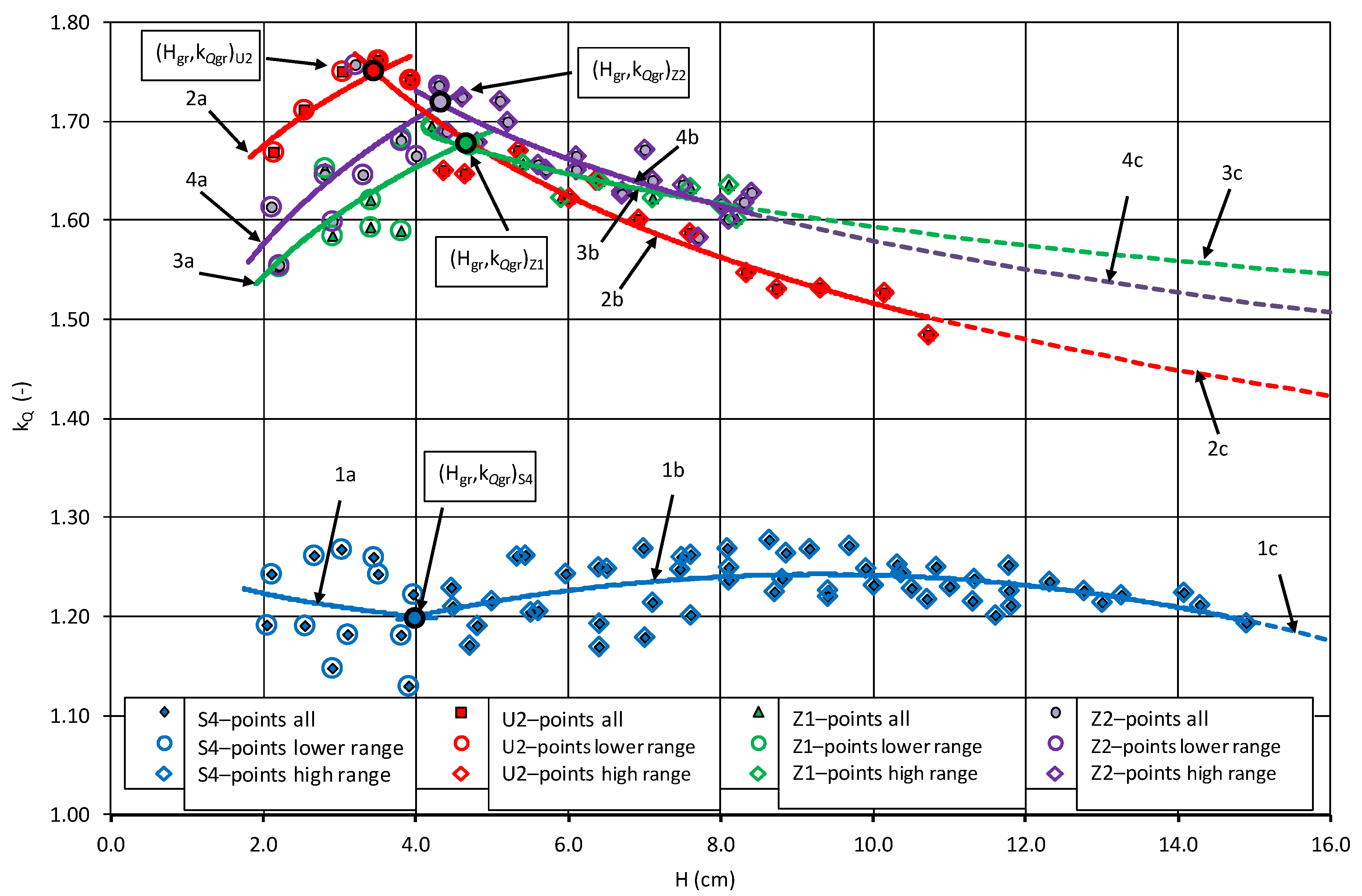
- The capacity of regulators with beams with a developed shape in the plan depends on the shape of the overflow plan described by the type of U and Z beams, the height of the sill P, and the height of the elevation of the upper water above the overflow H (Figure 8). With water depth above the control overflow crest up to 4.0 cm, the flow increase for the U beams in the plan is greater than that for the Z beams with a refracted shape in the plan (curve 2a compared to curves 3a and 4a in Figure 8).
- At the same sill height P, for fillings smaller than 4.0 cm, curvilinear U beams have a higher value of modular flow coefficient than the Z beams with a refracted shape. With fillings greater than 4.0 cm, the opposite relationship occurs (curve 2 compared to curve 3 in Figure 8). The height of the overflow sill for the same beam shape in the plan (Z1 and Z2 variants) changes the value of the modular flow coefficient (curve 3 compared to curve 4 in Figure 8).
Author Contributions
Funding
Institutional Review Board Statement
Informed Consent Statement
Data Availability Statement
Acknowledgments
Conflicts of Interest
References
- Climate Change 2014 Synthesis Report, IPICC, 2015, Switzerland. Available online: https://www.ipcc.ch/site/assets/uploads/2018/02/SYR_AR5_FINAL_full.pdf (accessed on 11 February 2022).
- PGWP 2019. Projekt Plan Przeciwdziałania Skutkom Suszy (PPSS). Państwowe Gospodarstwo Wody Polskie, Warszawa, Sierpień 2019. Available online: https://www.wody.gov.pl/nasze-dzialania/stop-suszy (accessed on 11 February 2022). (In Polish)
- Przybyła, C.Z.; Szafrański, C.Z. Water management problems in agriculture in Wielkopolska. Water Environ. Rural Areas 2004, 4, 25–38. [Google Scholar]
- Wilderer, P.A. Applying Sustainable Water Management Concepts in Rural and Urban Areas: Some Thoughts About Reasons, Means and Needs. Water Sci. Technol. 2004, 49, 8–16. [Google Scholar] [CrossRef] [PubMed]
- Ankum, P.; Renault, D. Modernization of Irrigation Systems–Technical Modules; FAO Land & Water Division, Masscote: Rome, Italy, 2008; pp. 1–32. [Google Scholar]
- Machiels, O.; Erpicum, S.; Dewals, B.J.; Archambeau, P.; Pirotton, M. Piano Key Weirs: The experimental study of an efficient solution for rehabilitation. WIT Trans. Ecol. Environ. 2010, 133, 95–106. [Google Scholar] [CrossRef]
- Oleszczuk, R.; Stocka, I.; Urbański, J.; Hewelke, E. Ocena stanu technicznego budowli wodno-melioracyjnych na obiekcie nawodnień podsiąkowych Solec. Wiadomości Melior. I Łąkarskie 2016, 2, 72–76. (In Polish) [Google Scholar]
- Oleszczuk, R.; Stocka, I.; Urbański, J.; Hewelke, E. Stan techniczny budowli piętrzących na przykładzie wybranego systemu nawodnień podsiąkowych. Water Environ. Rural Areas 2017, 17, 89–100. (In Polish) [Google Scholar]
- Schuurmans, J.; Hof, A.; Dijkstra, S.; Bosgra, O.H.; Brouwer, R. Simple Water Level Controller for Irrigation and Drainage Canals. J. Irrig. Drain. Eng. 1999, 125, 189–195. [Google Scholar] [CrossRef]
- Popek, Z.; Bajkowski, S.; Siwicki, P.; Urbański, J. Laboratory Tests of New Groundwater Table Level Regulators in Subsurface Drainage Systems. Water 2021, 13, 631. [Google Scholar] [CrossRef]
- Skaggs, R.W.; Fausey, N.R.; Evans, R.O. Drainage water management. J. Soil Water Conserv. 2012, 67, 167A–172A. [Google Scholar] [CrossRef]
- Smedema, L.K.; Vlotman, W.F.; Rycroft, D.W. Modern Land Drainage: Planning, Design and Management of Agricultural Drainage Systems; CRC Press: Abingdon, UK, 2004; p. 449. [Google Scholar] [CrossRef]
- Szejba, D.; Bajkowski, S. Determination of Tile Drain Discharge under Variable Hydraulic Conditions. Water 2019, 11, 120. [Google Scholar] [CrossRef]
- Bajkowski, S. Discharge coefficients of the horizontal vortex chamber. Sci. Pap. Univ. Agric. Krakow Environ. Engineer. Ser. 2001, 21, 673–681. (In Polish) [Google Scholar]
- Subhash, C.; Jain, M. Free-surface swirling flows in vertical dropshaft. J. Hydraul. Eng. 1987, 113, 1277–1289. [Google Scholar]
- Bajkowski, S. Hydraulic properties of horizontal vortex chamber. Adv. Hydro-Sci. Eng. 2002, 150, 47–58. (In Polish) [Google Scholar]
- Bos, M.G. Discharge Measurement Structures. International Institute for Land Reclamation and Improvement, 3rd ed.; International Institute for Land Reclamation and Improvement: Wageningen, The Netherlands, 1989; p. 402. [Google Scholar]
- Bajkowski, S. Submerged sharp-crested morning-glory-spillway criteria of submergence and the discharge coefficients. Model. Investig. Hydro-Eng. 1987, 51, 5–15. [Google Scholar]
- Harada, M. The Society of Instrument and Control Engineers. In Fluid Control and Measurement; Pergamon Press: Tokyo, Japan, 1986; Volume 1, p. 587. [Google Scholar]
- Voron, B. Regulation and management of water in irrigation canals and water saving irrigation methods and technologies. La Houille Blanche 1995, 4, 72–81. [Google Scholar] [CrossRef][Green Version]
- Frankenberger, J.; Kladivko, E.; Sands, G.; Jaynes, D.; Fausey, N.; Helmers, M.; Brown, L. Drainage Water Management for the Midwest: Questions and Answers about Drainage Water Management for the Midwest; Purdue Extension: West Lafayette, IN, USA, 2006; 8p. [Google Scholar]
- Jaynes, D.B. Changes in yield and nitrate losses from using drainage water management in central Iowa. J. Soil Water Conserv. 2012, 67, 485–494. [Google Scholar] [CrossRef]
- Sunohara, M.D.; Gottschall, N.; Craiovan, E.; Wilkes, G.; Topp, E.; Frey, S.K.; Lapen, D.R. Controlling tile drainage during the growing season in Eastern Canada to reduce nitrogen, phosphorus, and bacteria loading to surface water. Agric. Water Manag. 2016, 178, 159–170. [Google Scholar] [CrossRef]
- Sojka, M.; Kozłowski, M.; Stasik, R.; Napierała, M.; Kęsicka, B.; Wróżyński, R.; Jaskuła, J.; Liberacki, D.; Bykowski, J. Sustainable Water Management in Agriculture—The Impact of Drainage Water Management on Groundwater Table Dynamics and Subsurface Outflow. Sustainability 2019, 11, 4201. [Google Scholar] [CrossRef]
- Brandyk, A.; Kaca, E.; Oleszczuk, R.; Urbański, J.; Jadczyszyn, J. Conceptual Model of Drainage-Sub Irrigation System Functioning-First Results from a Case Study of a Lowland Valley Area in Central Poland. Sustainability 2021, 13, 107. [Google Scholar] [CrossRef]
- Pietrucha, J.; Gralewski, J.; Kolasiński, D. Device for Water Level Control. Patent Office of the Republic of Poland Patent 237597, 2021. [Google Scholar]
- Żbikowski, A.; Bajkowski, S.; Batijewski, W.; Dąbkowski, L.; Kubrak, J.; Lipka, W. Wytyczne wymiarowania przelewów i ich kanałów odprowadzających w budowlach wodnomelioracyjnych. In Obliczenia Hydrauliczne Przelewów Budowli Wodno-Melioracyjnych; Okruszko, H., Ed.; BiblioteczkaWiadomości IMUZ: Warsaw, Poland, 1986; Volume 67, pp. 9–93. (In Polish) [Google Scholar]
- Bekheet, A.A.; AboulAtta, N.M.; Saa, N.Y.; El-Molla, D.A. Effect of the shape and type of piano key weirs on the flow efficiency. Ain Shams Eng. J. 2022, 13, 1–15. [Google Scholar] [CrossRef]
- Nezami, F.; Farsadizadeh, D.; Nekooie, M.A. Discharge coefficient for trapezoidal side weir. Alexandria University. Alex. Eng. J. 2015, 54, 595–605. [Google Scholar] [CrossRef]
- Emiroglu, M.E.; Kaya, N.; Agaccioglu, H. Discharge Capacity of Labyrinth Side Weir Located on a Straight Channel. J. Irrig. Drain. Eng. 2010, 136, 37–46. [Google Scholar] [CrossRef]
- Sadeghian, H.; Parvaneh, A.; Nekooie, M.A.; Parvaneh, M. Discharge characteristics of triangular labyrinth side weirs (with inclined bed) located on a straight channel. In Proceedings of the 38th Iahr World Congress, Panama City, Panama, 1–6 September 2019; pp. 1–7. [Google Scholar] [CrossRef]
- Ikinciogullari, E.; Emiroglu, M.E. Estimation of triangular labyrinth side weir discharge capacity using schmidt approach. Sigma J. Eng. Nat. Sci. 2019, 37, 289–303. [Google Scholar]
- Khalili, M.; Honar, T. Discharge Coefficient of Semi-Circular Labyrinth Side Weir in Subcritical Flow. WSA 2017, 43, 433. [Google Scholar] [CrossRef]
- Dursun, O.F.; Kaya, N.; Firat, M. Estimating Discharge Coefficient of Semi-Elliptical Side Weir Using ANFIS. J. Hydrol. 2012, 426–427, 55–62. [Google Scholar] [CrossRef]
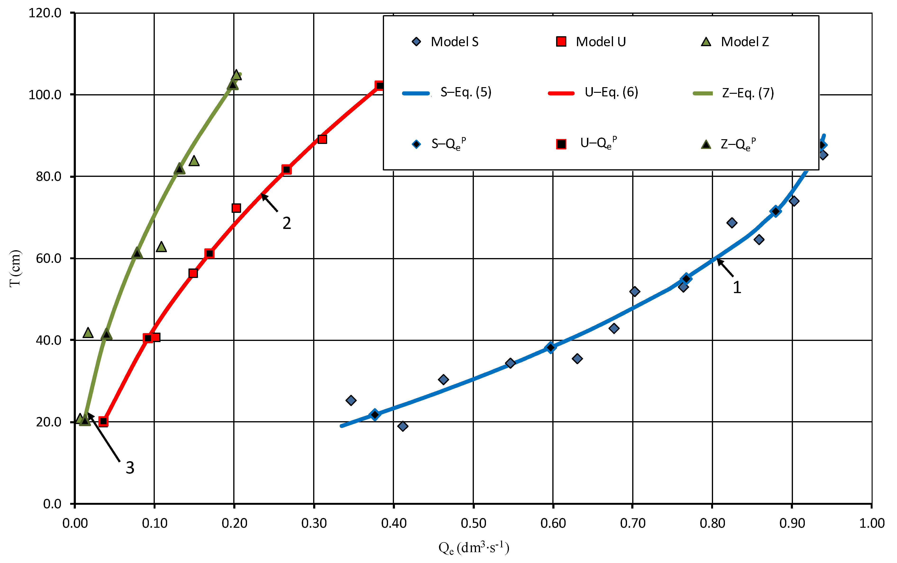
| No. | Model | Module | b (m) | Lp (m) | Lk (cm) | kr | Variant | P (cm) | Qe (dm3·s−1) |
|---|---|---|---|---|---|---|---|---|---|
| 1 | 2 | 3 | 4 | 5 | 6 | 7 | 8 | 9 | 10 |
| 1. | C (sharp-crested) | M45 | 0.450 | 0.450 | 1.2 | C4–S4 | 71.5 | ||
| 2. | M59 | 0.588 | 0.588 | 0.9 | 1.00 | C2–U2 | 40.5 | ||
| 3. | M54 | 0.544 | 0.544 | 1.1 | C1–Z1 | 20.5 | |||
| 4. | M54 | 0.544 | 0.544 | 1.1 | C2–Z2 | 41.6 | |||
| 5. | S (rectilinear) | S5 | 87.7 | 0.937 | |||||
| 6. | S4 | 71.5 | 0.879 | ||||||
| 7. | M45 | 0.450 | 0.450 | 1.2 | 1.00 | S3 | 55.0 | 0.767 | |
| 8. | S2 | 38.2 | 0.597 | ||||||
| 9. | S1 | 21.8 | 0.376 | ||||||
| 10. | S0 | 6.8 | 0.000 | ||||||
| 11. | U (labyrinth) | U5 | 102.2 | 0.383 | |||||
| 12. | U4 | 81.7 | 0.266 | ||||||
| 13. | M59 | 0.588 | 0.935 | 0.9 | 1.58 | U3 | 61.2 | 0.169 | |
| 14. | U2 | 40.5 | 0.092 | ||||||
| 15. | U1 | 20.2 | 0.036 | ||||||
| 16. | U0 | 0.0 | 0.000 | ||||||
| 17. | Z (compound) | Z5 | 102.6 | 0.198 | |||||
| 18. | Z4 | 82.0 | 0.131 | ||||||
| 19. | M54 | 0.544 | 0.967 | 1.1 | 1.74 | Z3 | 61.4 | 0.078 | |
| 20. | Z2 | 41.6 | 0.040 | ||||||
| 21. | Z1 | 20.5 | 0.013 | ||||||
| 22. | Z0 | 0.0 | 0.000 |
| No. | Variant | Variable | Qc (dm3·s−1) | T (cm) | H (cm) | Re | H/P | H/Lk | H/B |
|---|---|---|---|---|---|---|---|---|---|
| 1 | 2 | 3 | 4 | 5 | 6 | 7 | 8 | 9 | 10 |
| 1 | S4 (rectilinear) | max | 55.90 | 86.39 | 14.89 | 1.56 × 10⁵ | 0.21 | 12.34 | 0.139 |
| 2 | average | 24.39 | 79.34 | 7.84 | 7.43 × 10⁴ | 0.11 | 6.50 | 0.073 | |
| 3 | min | 3.70 | 73.54 | 2.04 | 1.33 × 10⁴ | 0.03 | 1.69 | 0.019 | |
| 4 | U2 (labyrinth)  | max | 57.36 | 51.22 | 10.72 | 1.55 × 10⁵ | 0.26 | 12.60 | 0.100 |
| 5 | average | 29.13 | 46.59 | 6.09 | 7.10 × 10⁴ | 0.15 | 7.16 | 0.057 | |
| 6 | min | 7.20 | 42.63 | 2.13 | 1.36 × 10⁴ | 0.05 | 2.50 | 0.020 | |
| 7 | Z1 (compound) | max | 39.28 | 28.70 | 8.20 | 1.05 × 10⁵ | 0.40 | 7.67 | 0.077 |
| 8 | average | 20.98 | 25.51 | 5.01 | 5.51 × 10⁴ | 0.24 | 4.68 | 0.047 | |
| 9 | min | 6.44 | 22.70 | 2.20 | 1.43 × 10⁴ | 0.11 | 2.06 | 0.021 | |
| 10 | Z2 (compound) | max | 40.85 | 50.00 | 8.40 | 1.07 × 10⁵ | 0.20 | 7.86 | 0.079 |
| 11 | average | 23.25 | 47.02 | 5.42 | 6.53 × 10⁴ | 0.13 | 5.07 | 0.051 | |
| 12 | min | 6.31 | 43.70 | 2.10 | 1.43 × 10⁴ | 0.05 | 1.97 | 0.020 |
| No. | Parameter | S4 | U2 | Z1 | Z2 |
|---|---|---|---|---|---|
| 1 | 2 | 3 | 4 | 5 | 6 |
| Curve in Figure 7 | 1 | 2 | 3 | 4 | |
| 1 | a1 | 1.0 | 0.1871 | 0.2798 | 0.2408 |
| 2 | b1 | 1.5 | 2.0 | 2.0 | 2.0 |
| 3 | a2 | 0.0 | 3.4250 | 2.5577 | 2.8244 |
| 4 | b2 | 0.0 | 1.0 | 1.0 | 1.0 |
| 5 | c1 = Qe (dm3·s−1) | 0.8794 | 0.0917 | 0.0126 | 0.0397 |
| 6 | r | 0.9956 | 0.9983 | 0.9984 | 0.9985 |
| 7 | R2 | 0.9987 | 0.9990 | 0.9987 | 0.9978 |
| 8 | N | 65 | 17 | 18 | 28 |
| No. | Parameter | S4 | U2 | Z1 | Z2 |
|---|---|---|---|---|---|
| 1 | 2 | 3 | 4 | 5 | 6 |
| Lower zone | |||||
| 1 | Curve in Figure 8 | 1a | 2a | 3a | 4a |
| 2 | Hmin (cm) | 2.04 | 2.13 | 2.20 | 2.10 |
| 3 | Qmin (dm3·s−1) | 3.70 | 7.20 | 6.44 | 6.31 |
| 4 | a3 | 1.2473 | 1.5871 | 1.4413 | 1.4589 |
| 5 | b3 | −0.0280 | 0.0779 | 0.0991 | 0.1115 |
| 6 | a4, b4, c2 | 0.0 | 0.0 | 0.0 | 0.0 |
| 7 | r | −0.1810 | 0.8327 | 0.7692 | 0.7092 |
| 8 | R2 | 0.0272 | 0.7675 | 0.5976 | 0.5229 |
| 9 | N | 12 | 5 | 10 | 9 |
| Border point | |||||
| 10 | Hgr (cm) | 3.98 | 3.48 | 4.58 | 4.32 |
| 11 | kQgr (dm3·s−1) | 1.20 | 1.75 | 1.68 | 1.72 |
| Upper zone | |||||
| 14 | Curve in Figure 8 | 1b | 2b | 3b | 4b |
| 15 | a3 | −0.0015 | 2.0691 | 1.8489 | 1.9885 |
| 16 | b3 | 2.0 | −0.1350 | −0.0646 | −0.1001 |
| 17 | a4 | 0.0279 | 0.0 | 0.0 | 0.0 |
| 18 | b4 | 1.0 | 0.0 | 0.0 | 0.0 |
| 19 | c2 | 1.113 | 0.0 | 0.0 | 0.0 |
| 20 | r | 0.0268 | −0.9549 | −0.8671 | −0.8683 |
| 21 | R2 | 0.2071 | 0.9318 | 0.7917 | 0.7719 |
| 22 | N | 53 | 14 | 10 | 20 |
| 23 | Hmax (cm) | 14.89 | 10.72 | 8.20 | 8.40 |
| 24 | Qmax (dm3·s−1) | 55.90 | 57.36 | 39.28 | 40.85 |
Publisher’s Note: MDPI stays neutral with regard to jurisdictional claims in published maps and institutional affiliations. |
© 2022 by the authors. Licensee MDPI, Basel, Switzerland. This article is an open access article distributed under the terms and conditions of the Creative Commons Attribution (CC BY) license (https://creativecommons.org/licenses/by/4.0/).
Share and Cite
Bajkowski, S.; Urbański, J.; Oleszczuk, R.; Siwicki, P.; Brandyk, A.; Popek, Z. Modular Regulators of Water Level in Ditches of Subirrigation Systems. Sustainability 2022, 14, 4103. https://doi.org/10.3390/su14074103
Bajkowski S, Urbański J, Oleszczuk R, Siwicki P, Brandyk A, Popek Z. Modular Regulators of Water Level in Ditches of Subirrigation Systems. Sustainability. 2022; 14(7):4103. https://doi.org/10.3390/su14074103
Chicago/Turabian StyleBajkowski, Sławomir, Janusz Urbański, Ryszard Oleszczuk, Piotr Siwicki, Andrzej Brandyk, and Zbigniew Popek. 2022. "Modular Regulators of Water Level in Ditches of Subirrigation Systems" Sustainability 14, no. 7: 4103. https://doi.org/10.3390/su14074103
APA StyleBajkowski, S., Urbański, J., Oleszczuk, R., Siwicki, P., Brandyk, A., & Popek, Z. (2022). Modular Regulators of Water Level in Ditches of Subirrigation Systems. Sustainability, 14(7), 4103. https://doi.org/10.3390/su14074103


