Concept Paper

Vulnerable Road User Protection from Heavy Goods Vehicles Using Direct and Indirect Vision Aids

by
Richard J. Frampton
1,* and
Jack E. Millington
2
1
School of Design and Creative Arts, Loughborough University, Loughborough LE11 3TU, UK
2
Department of Aeronautical and Automotive Engineering, Loughborough University, Loughborough LE11 3TU, UK
*
Author to whom correspondence should be addressed.
Sustainability 2022, 14(6), 3317; https://doi.org/10.3390/su14063317
Submission received: 30 December 2021 / Revised: 28 February 2022 / Accepted: 1 March 2022 / Published: 11 March 2022
(This article belongs to the Special Issue Current and Future Issues in Transportation Safety and Sustainability)

Abstract

:
In Europe, heavy goods vehicles (HGVs) are disproportionately involved in serious and fatal collisions with vulnerable road users (VRUs). An interrogation of 2019 national crash data for Great Britain (Stats19) suggested that detection of cyclists and pedestrians in the nearside and front blind spots of HGVs is still a significant problem during forward or left-turn manoeuvres of the HGV. To improve detection, Transport for London introduced Direct Vision and Safe System Standards in 2021 for HGVs entering the Greater London area. This research assessed the efficacy of one of the Safe System requirements—the fitment of sensors to detect vulnerable road users on the nearside of the vehicle. A physical testing procedure was developed to determine the performance of a sensor system meeting the Transport for London Safe System requirements. Overall, the Safe System compliant sensor system missed 52% of expected detection nodes on the nearside of the vehicle. A total of 56% of the “stop vehicle” nodes, 45% of the “slow down” and 48% of the “proceed with caution” nodes were not recognised. The most forward sensor did not fully cover the front-left corner blind spot, missing 70% of the desired detection nodes. Nearside sensor systems fitted to Safe System requirements may cover a reasonable area but could still leave many undetected zones to the left and front of the vehicle. Standardising sensor range and location could help to eliminate sensor blind spots. Mandating additional front sensors would help cover the blind spot at the front-left corner of the HGV.

1. Introduction

Road traffic casualties caused by mixing heavy goods vehicles (HGVs) and vulnerable road users (VRUs) on Europe’s roads is a well-documented problem. An annual report from the Volvo Group [1] analysed 2014 European road crash injury data and found that, of the 26,000 EU fatalities, 15% were due to HGVs, while HGVs made up only 3% of the traffic volume. Of the HGV-related fatalities, 32% were vulnerable road users and of the 1230 VRU fatalities, 53% were pedestrians, 22% cyclists and 25% moped riders or motorcyclists. The Volvo research also examined the scenarios in which crashes occurred, reporting that an HGV turning to the nearside was the most dangerous and frequently occurring crash scenario between cyclists and HGVs and was most common in urban areas. Note that a nearside turn equates to a left turn for a right-hand-drive vehicle driving on the left and a right turn for a left-hand-drive vehicle driving on the right.
Meanwhile, virtual modelling of HGV cabs carried out by Summerskill and Marshall [2] concluded that all standard vehicle configurations have blind spots which can hide VRUs from the driver’s direct vision. Other research conducted by Marshall et al. [3] used 2010–2015 STATS-19 police data to investigate the scenarios related to HGV and VRU crashes in Great Britain. The research found that 32% of all impacts between HGVs and VRUs occurred when the HGV was moving off forwards, but 58% of impacts which resulted in serious injury or fatality occurred during a turn to the nearside—in other words, a left-turn manoeuvre for the right-hand-drive vehicles in the sample.
The issue of HGV vision (“blind spots”) has been known for some time, and various European regulations have been developed in an attempt to improve matters. For example, European directive 2003/97/EC concerning type approval of devices for indirect vision [4] states that in conjunction with the standard class III and IV mirrors on the vehicle, N3 vehicles (goods vehicles in excess of 12 tonnes) must be fitted with both class V and VI mirrors to minimise blind spots to the nearside kerb area and nearside front of the vehicle, respectively. The directive clearly outlines the overall requirement to fit the devices, alongside the dimensions and visible area needed for these mirrors. More recently, active safety systems have been legally mandated. A level 1 advanced emergency braking system (AEBS) has been mandatory for new types of HGV over 7.5t since 2015, in an obligation outlined under EC Regulation 661/2009 [5], and level 2 AEBS became mandatory for new types from 1 November 2018 [6]. The systems currently on the market are effective in targeting collisions with vehicles ahead, yet recent Euro-NCAP light commercial vehicle tests [7] indicate such systems have difficulty in detecting pedestrians and other vulnerable road users compared to the systems used on passenger cars.
In 2018, Transport for London (TfL) reported statistics showing that between 2015 and 2017, HGVs were disproportionately involved in fatal collisions with vulnerable road users in the British capital. A total of 63% of killed cyclists and 25% of killed pedestrians were associated with an HGV impact, despite HGVs making up only 4% of the overall miles driven in the capital [8]. This was not a sustainable situation and did not fit with the Vision Zero philosophy to eradicate all deaths and serious injuries from London’s streets by 2041 [9]. Research commissioned by TfL [10] contributed to the requirement for all vehicles of more than 12 tonnes in gross vehicle weight (GVW) to possess an HGV safety permit [11] to operate in Greater London from October 2020. The safety permit is granted providing the vehicle meets the Direct Vision Standards (DVS) developed by TFL to address the high number of collisions in London involving HGVs and people walking or cycling. The DVS objectively measures how much a driver can see through their cab windows and mirrors and how big the resulting blind spots are. This is communicated as a star rating from zero (poor) to five (excellent), which indicates the level of risk to people walking and cycling near the vehicle. If the HGV is not capable of achieving at least one star in the DVS, it can still enter London provided it has fitted equipment which meets the TfL Safe System (SS) requirements [11]. Essentially, this comprises a class V mirror fitted to the nearside kerb area, a class VI mirror to the nearside vehicle front, a fully operational camera monitoring system fitted to the nearside of the vehicle and a sensor system also mounted to the nearside alerting the driver to the presence of a cyclist or pedestrian (sensors are to be placed along the nearside of the vehicle covering a 6 m length from the front or 1 m from the rear to the front, whichever is shortest). No specific make or brand of equipment or technology is mandated as part of the Safe System, and the sensor systems are viewed as being very much non-OE, postproduction fitments by third-party companies. TfL considers direct vision as the future in creating safer vehicles and safer urban environments. However, they also realised that the HGV service life is much longer than that of passenger cars and that HGV manufacturers needed lead time to develop the next generation of cabs with enhanced direct vision. The introduction of the Safe System is intended to serve as a mitigation to enhance vehicle safety on London’s roads immediately until the more fundamental change of increased direct vision is achieved.
In a future transport system, we will still likely have a mix of pedestrians, cyclists and HGVs sharing the roads. In fact, the proportion of vulnerable road users will increase as we move toward a greener society. In that respect, the success or otherwise of the current HGV initiative in London could have important implications for future city safety.
The research conducted for this paper therefore had two main aims: first, to examine current real-world crash data in order to ascertain the most up-to-date collision factors associated with HGV to VRU collisions in Great Britain and determine the effect (if any) of changes to relevant safety regulations in recent years; and secondly, to analyse the efficacy of the TfL Safe System sensor requirements for HGVs that do not achieve the minimum one-star DVS rating.

2. Materials and Methods

2.1. Crash Data Analysis

In order to identify collision locations and scenarios associated with current HGV to VRU impacts, real-world crash data were utilised. Crashes which occur in Great Britain resulting in injury and are reported to the police are recorded on the national register known as Stats19. Stats19 data for 2019 was sourced for analysis; 2020 data was not used because the COVID-19 pandemic had skewed the road casualty picture. Research published by the Department for Transport [12] highlighted how total vehicle traffic was reduced by 21% compared to 2019. In STATS-19, data were stored for each collision within three distinct database files: Accidents, Vehicles and Casualties. There were a number of key variables analysed for HGV/VRU collisions.
Vehicle_type: The vehicles and other road users involved (e.g., HGVs above 7.5 tonnes, pedestrian, cyclist)
Vehicle_manoeuvre: the manoeuvre being performed when the accident occurred (e.g., turning left, going ahead)
First_point_of_impact: first point of contact between the vulnerable road user and the vehicle (e.g., front, offside, nearside, etc.)

2.2. Efficacy of Safe System Sensor Requirements

A test program was developed to assess the effectiveness of a sensor system fitted to a subject vehicle operating with equipment to a level accepted under the TfL Safe System.

2.2.1. Test Vehicle

Figure 1 shows the subject test vehicle. The vehicle was a Renault Trucks C430, with an 8 × 4 axle configuration and fitted with a Tipper body. The axle layout means that two axles in close proximity were fitted at the rear with two axles, further apart, fitted at the front. It was of N3G-type approval class, indicating suitability for on- and off-road use. The gross vehicle weight was 32 tonnes; as such, it fell into the remit of the TfL Direct Vision Standard. The base vehicle was rated as 0 stars under the DVS Assessment Protocol. Therefore, additional safety equipment was already fitted to a level acceptable under the Safe System, consisting of a combination of cameras and sensors.

2.2.2. Vehicle Mirrors

The test vehicle was fitted with the legally mandated class III through VI mirrors under UNECE regulation 46 [13]. This consisted of a pair of mirrors on both near- and offside of the vehicle, providing rearward and extended coverage to compensate for the height of the vehicle, along with a class V mirror placed on the near (passenger) side to provide vision to the kerbside blind spot and a class VI mirror providing vision to the front of the vehicle.

2.2.3. Camera System

A combination of 4 cameras was mounted to the test vehicle: a wide-angle rear-facing “ball” camera on the front wing of the vehicle at both nearside and offside, along with a front-facing camera fitted at the top of the windscreen and a reversing camera fitted at the rear of the chassis. These devices met the field of vision required by UNECE 46 devices for indirect vision.
The camera monitor was placed on top of the facia and was an OEM multifunction unit, allowing camera, satnav and infotainment functions. The 4 cameras could be viewed individually or as a 4-in-one matrix through the use of 4 touchscreen buttons. These buttons also made it possible to navigate away from camera view to other display functions. When in camera mode, the application of direction indicator switches shifted the camera output view to either the left or right camera.

2.2.4. Sensors

A series of 4 ultrasonic sensors were fitted along the nearside of the test vehicle. The system was supplied and fitted by the sensor manufacturer TVG [14]. This was fitted at point of vehicle delivery by an approved TVG technician and met the warning sensor coverage requirements for the TfL Safe System. Sensor locations were measured at each of the 4 locations along the vehicle. Measurements were taken relative to the front axle of the vehicle and all subsequent axles. Table 1 shows the sensor locations on the C430 test vehicle. Figure 2, Figure 3, Figure 4 and Figure 5 show the four sensors fitted. Sensors are numbered from front to rear, with Sensor 1 being the most forward, and sensor 4 the most rearward.
A Renault Trucks Tridem (Figure 6) also fitted with a TVG sensor system complying with TfL requirements was available for comparison. The Tridem had an identical cab design to the C430 test vehicle but with a different axle configuration (1 × 3). This vehicle had three axles in close proximity fitted to the rear with one axle fitted to the front.
The Tridem was not used in the nearside sensor system tests but solely as a comparison vehicle to show how different axle configurations may affect where sensors can be placed. Table 2 shows the sensor locations on the Tridem, and Figure 7 compares sensor fitment on the C430 to that on the Tridem, both in relation to the required TfL coverage area.
Due to the almost identical cab design between the C430 test vehicle with an 8 × 4 axle layout and the Tridem vehicle with a 1 × 3 axle layout, the front two sensors were placed identically. However, Sensors 3 and 4 differed in position as the axle configuration restricted options for placement. With the 8 × 4 axle, a sensor was placed to the rear of the second axle, whereas on the Tridem this sensor was placed ahead of the axle. The fourth and final sensor was placed prior to axle 3 on the 8 × 4 layout, yet on the Tridem this was placed to the very rear of the vehicle, rearward of axle 4.

2.2.5. Driver Alert System and Sensor Calibration

A red–amber–green warning light was mounted to the vehicle A-pillar on the passenger (near) side, with a self-contained audible warning buzzer in the component casing (Figure 8). The sensor detection information for each warning level is shown in Table 3.

2.2.6. Testing Protocol

A pedestrian target was moved in the test area to the nearside of the vehicle, and the extent of sensor detection was quantified.
Test area for 6 m Standard—the requirements of the Safe System Standard mandates “coverage six metres down the nearside or one metre from the rear of the vehicle, whichever is smaller” [11]. This coverage formed the basis of the formulation of the test area. The Safe System fitting guide recommends a coverage of 6 m from the front of the vehicle, yet this measure is somewhat unclear due to the difficulty in defining what is exactly the front, with additional bumpers and accessories, among other items, altering the measure when physically testing a vehicle. For the purposes of the test, the front was defined with reference to the front axle, as this is a defined variable within the Body Exchange Parameters (BEP) used within industry. It was decided to define the vehicle front as 1 m from the BEP front axle location, allowing the sensor locations and coverage map to be defined with reference to this datum point. Building on the physical direct visibility assessment developed by Summerskill et al. [15], a grid map was formulated for this study performing tests for detection every 0.2 m away from the vehicle. This interval was the transitioning point between system warning levels. The fitted system only provided coverage up to 0.8 m from the vehicle. After this point, the target was not detected and further coverage was classed as “non-activation”. Due to the sensor range, tests were terminated at 1 m in this study. The test grid is shown in Figure 9.
Pedestrian target—The pedestrian surrogate was set to a height equivalent to that of a 5th percentile Italian female—1267 mm. This is the same dimension used in both the CAD-derived and manual assessment methods of a vehicle’s direct vision [15,16] and essentially represents a worst-case scenario in terms of detection. A tripod was used, as this allowed height adjustment with a flat surface mounted to it to allow detection. The width of this surface was selected arbitrarily at 565 mm, but activation was found to reliably occur in initial practice tests. The target was moved with its wide side facing the side of the HGV. Figure 10 shows the test target used.
Test procedure—A number of small cones were placed in an array covering the test zone (Figure 11), and a test operative put the test target in place upon each of these cones, then proceeded to the driver’s side to enter the cab and determine the activation status of the system. It was important that the operative entered through the driver’s (offside) door so as not to interfere with the sensors and create a false-positive reading. Assessing activation at each point across the grid map allowed field of vision diagrams (optical detection maps) to be produced.
Additional test area for forward coverage—an additional test ahead of the vehicle was performed to detect the extent of forward coverage of the most forward sensor located on the front corner of the vehicle and obtain data outside the Safe-System-required area. Again, a grid map was formulated, and a test taken at every 0.2 m across this. Figure 12 shows the marker cones ahead of the vehicle. This extended grid area covered the front blind spot into which a pedestrian or cyclist could move.

2.2.7. Weather Conditions during Testing

The tests were undertaken on bright sunny days with an average daytime temperature of 16 °C with no external street or other forms of lighting. Wind was light and presented no issue to test completion.

3. Results

3.1. Crash Data Analysis

3.1.1. First Point of Contact

To examine the issue of blind spots around the HGV, its first point of contact with a pedestrian or road cyclist was examined. The results are shown in Table 4. The estimation was based on vehicle damage, witness statements, CCTV footage and skid mark evidence.
The front and nearside of the HGV were the areas focused upon in terms of blind spot mirrors and sensing systems for VRU protection. The data analysis showed that pedestrians were most commonly in contact with the front of the HGV (44%) with the second most frequent point of contact being the HGV nearside (21%). The nearside of the HGV was clearly the most common impact point for cyclists (41%) with the vehicle front involved in a fewer number of collisions (19%). For pedestrians and cyclists combined, the HGV front was the most common impact point (34%), with the nearside being the second most frequent impact area (28%). Impacts to the front and nearside covered some 62% of HGV impacts with both pedestrians and cyclists.

3.1.2. Crash Data Analysis—HGV Manoeuvre

Knowledge of the HGV manoeuvre before impact with a VRU can help direct the development of technology countermeasures. Table 5 shows HGV manoeuvres before impact with pedestrians and cyclists. As with the first point of contact, the estimation was based on vehicle damage, witness statements, CCTV footage and skid mark evidence.
Turning left (21%) was clearly a feature more often associated with HGV impacts to cyclists than it was to impacts with pedestrians (5%). Conversely, going directly ahead was more often associated with HGV impacts to pedestrians (46%) than it was to impacts with cyclists (27%). Going directly ahead, slowing or stopping, moving off and turning left are all manoeuvres where improved VRU detection technology could be useful, and together they form 63% of all collisions with pedestrians and cyclists.

3.2. Efficacy of Side Warning Sensors

3.2.1. Sensor Performance in Specified 6 m Side Zone

The optical detection map in Figure 13 illustrates the expected sensor coverage across the 6 m zone for the system as tested, while Figure 14 is the actual optical detection map observed. The node colours red, orange and green correspond with the warning light colour, while blue nodes represent no light. Table 6 summarises the expected versus actual number of nodes covered.
Overall, the fitted sensor system missed 52% of the expected detection nodes. Breaking this down to levels of urgency, the system missed 56% of “stop vehicle” nodes, 45% of “slow down” nodes and 48% of “proceed with caution” nodes.

3.2.2. Sensor Performance of Most Forward Sensor

The optical detection map in Figure 15 illustrates the ideal forward coverage of the most forward mounted sensor. This ideal coverage would ensure that the forward blind spot at and slightly beyond the front corner would be covered. The leading edge of the vehicle front was 1.5 m ahead of the front axle. The node colours red, orange and green correspond with the warning light colour, while blue nodes represent no light. Figure 16 is the actual optical detection map observed, and Table 7 summarises the actual versus ideal number of nodes covered.
Overall, the fitted sensor system missed 70% of the ideal detection nodes. Breaking this down to levels of urgency, the system missed 68% of “stop vehicle” nodes, 73% of slow down” nodes and 73% of “proceed with caution” nodes.

4. Discussion

In Europe, efforts to minimise HGV blind spots to the nearside kerb area and nearside front have been ongoing for several years. Apart from improving direct vision from HGV cabs, the fitment of class V and VI mirrors is mandatory, and advanced emergency braking systems have been required since 2015 to help stop the vehicle if a vulnerable road user moves into the frontal blind spot. However, analysis of 2019 crash data for Great Britain (Stats19) suggested that the HGV “blind spot” problem has not gone away and supports the need for further improving VRU detection.
In March 2021, in a move to reduce vulnerable road user casualties associated with HGV impacts, Transport for London launched its Safety Permit Scheme for HGVs entering London. The scheme specifies minimum requirements for direct vision from HGV cabs, but failing these, an operating permit is granted providing the vehicle is equipped with a fully operational side camera monitoring system, class V and VI mirrors and a side sensor system which alerts the driver to a person walking or cycling on the nearside of the vehicle. The very inclusion of the sensor requirements suggests a recognition that cameras and mirrors alone may not be enough to provide adequate warning of the proximity of VRUs. In that regard, any sensor system would need to comprehensively cover the nearside and front corner blindspots of the HGV.
  • Performance of Nearside Sensor System
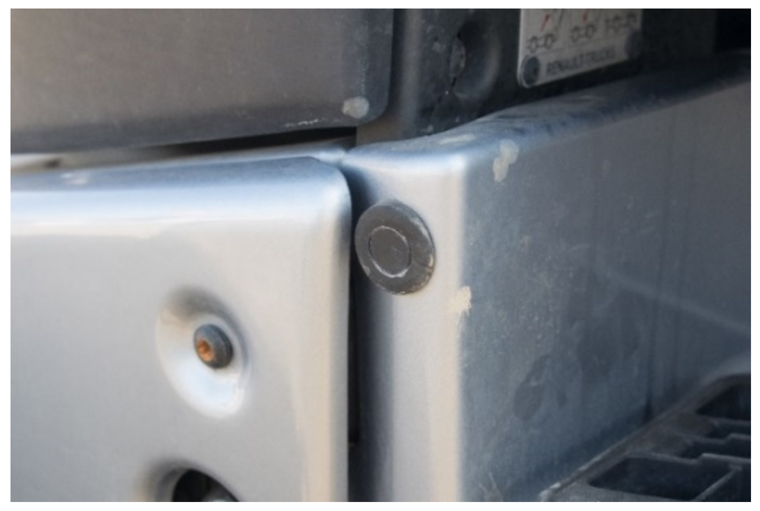
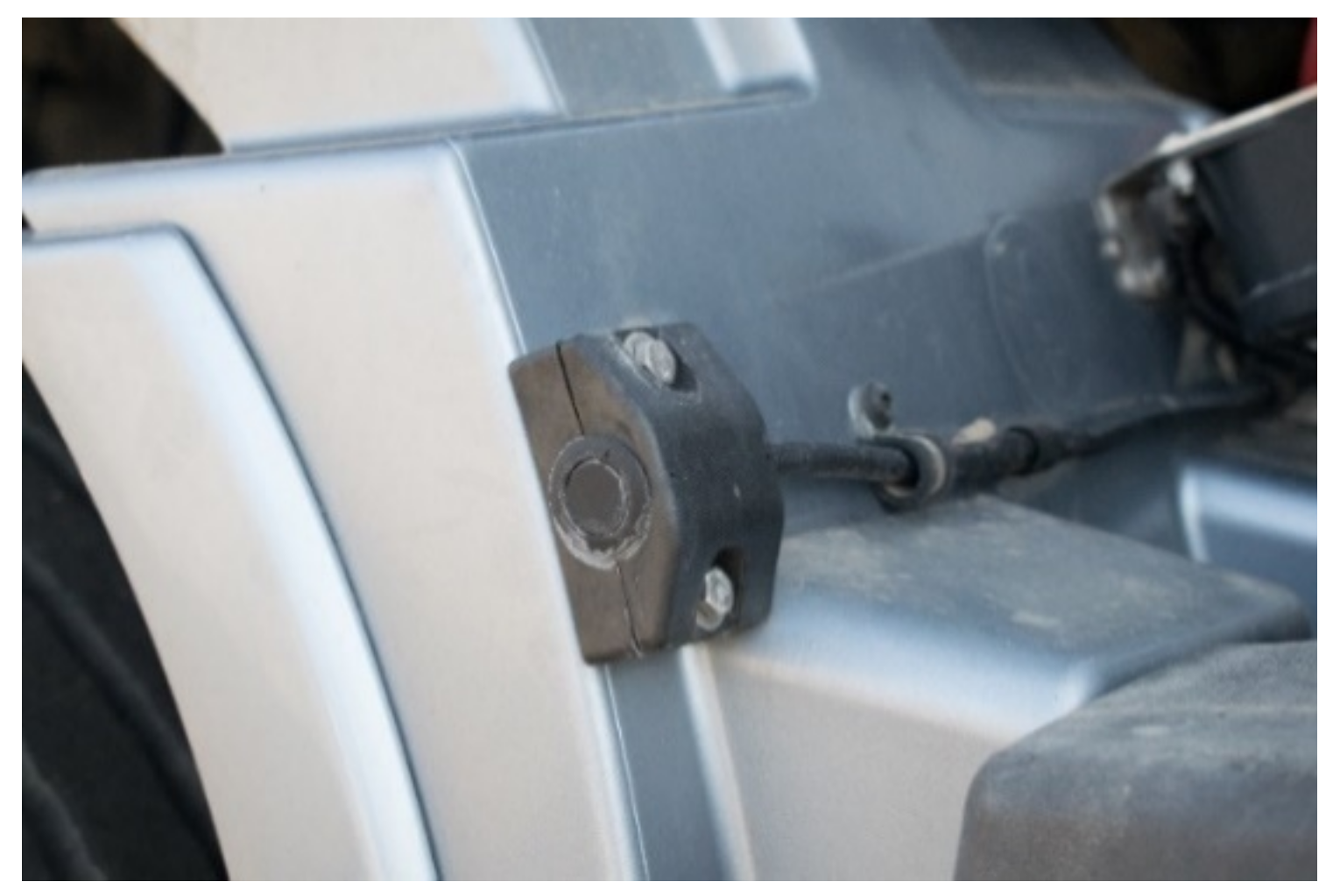
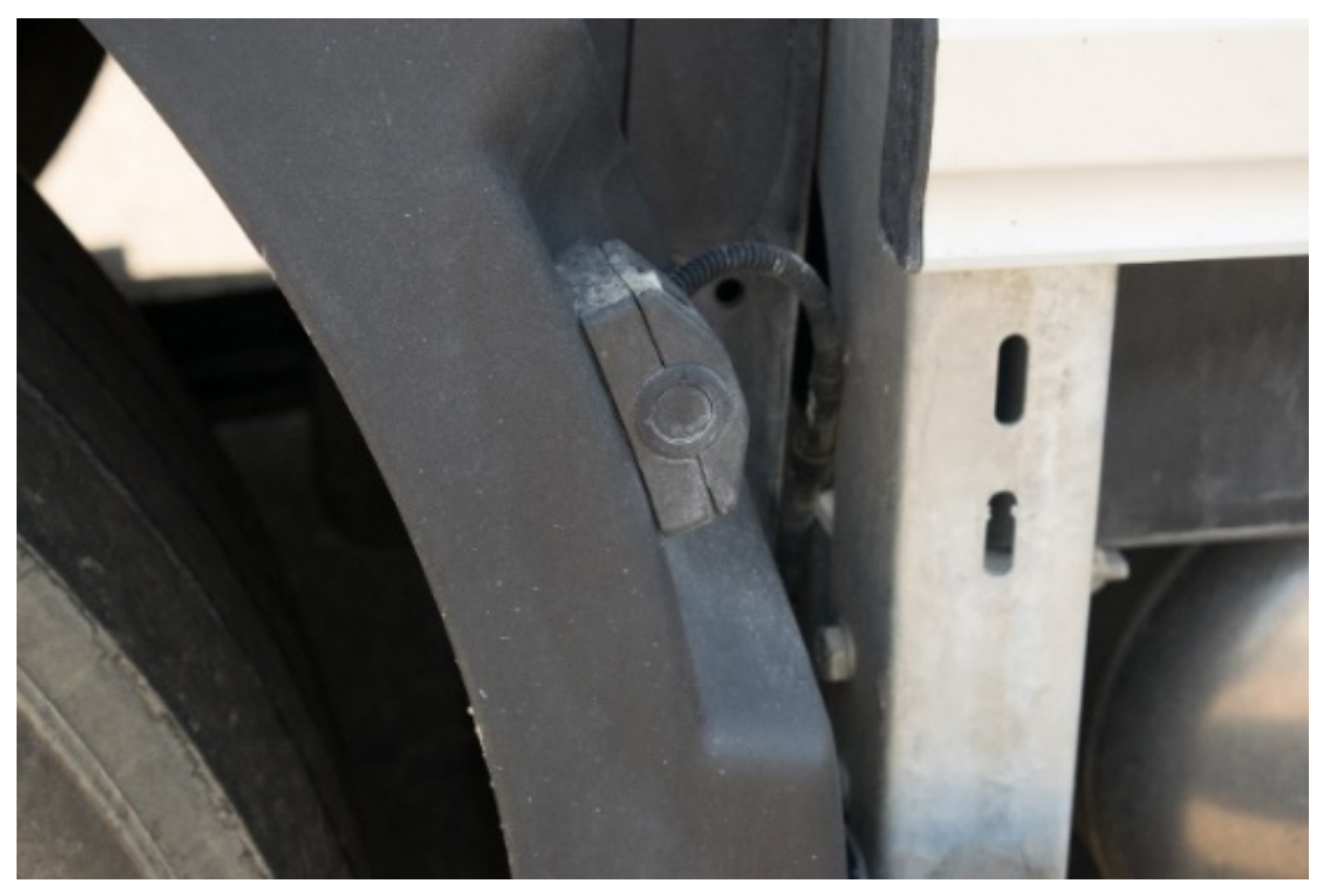
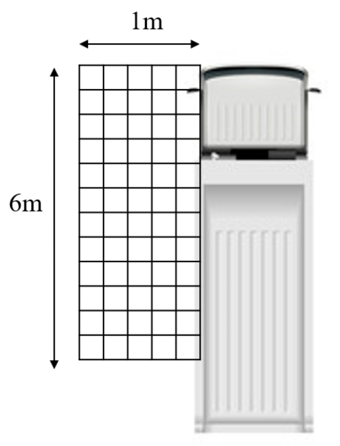
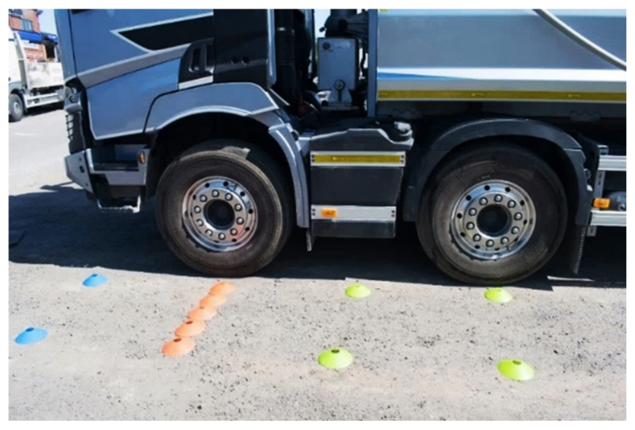
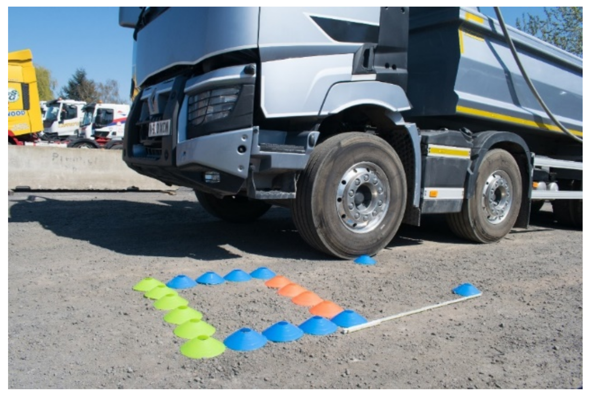
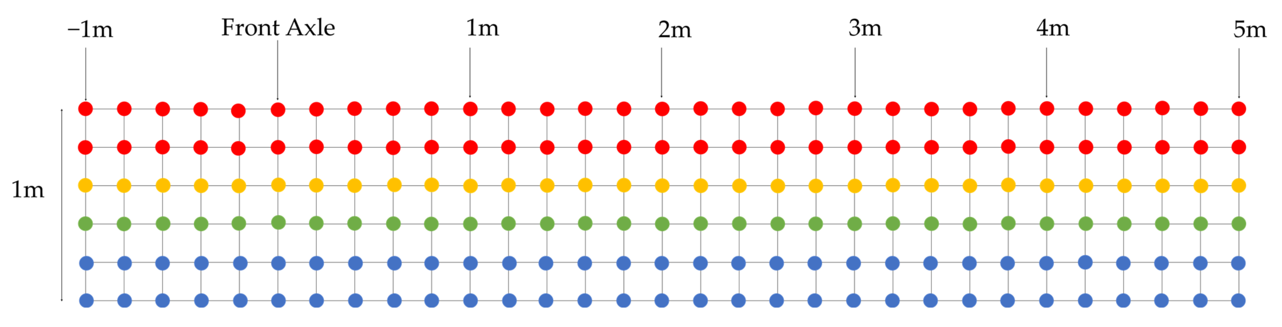
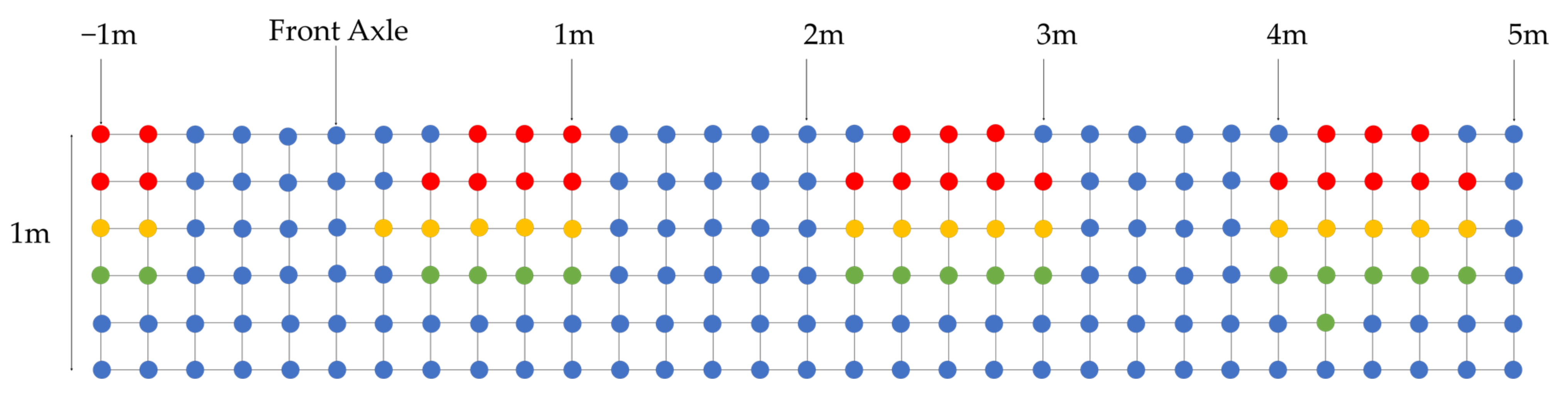
A nearside ultrasound sensor system, fitted in accordance with the requirements for the Safe System, was tested for accuracy and coverage using a small pedestrian surrogate. It was found to provide an overall coverage of 48% of the required nearside zone, a modest improvement compared to the 43% reported for a system using older technology in 2011 [17]. Despite this improvement, there were still significant blind spots which could present a danger to VRUs. The fitted system did not register 56% of critical “stop vehicle” nodes” and 45% of nodes where a “slow vehicle” recommendation was required, and it did not flag 48% of “proceed with caution” nodes. An additional concern was that zones of up to 1 m in length were blind within the test grid. This is especially of concern for pedestrians. The length of a typical adult pedal cycle means it is likely to be only partially in a zone of zero detection, and thus more visible. Yet, under cornering when the bike is angled or for a smaller object, for example a child’s bike, there is a chance of being lost from view. Indeed, some studies [18] suggest that when using only ultrasound as a detection medium, bicycles are more difficult to detect than pedestrians.
  • Performance of Front Corner Sensor
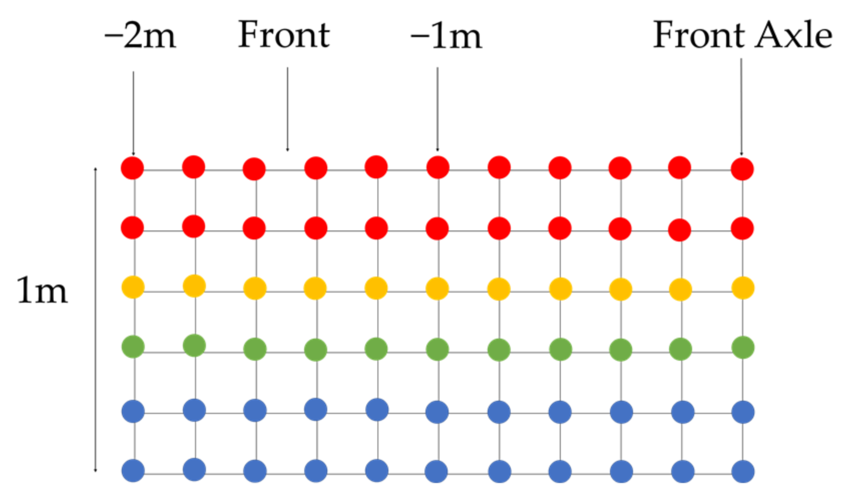
The most forward sensor provided poor coverage around the front nearside corner of the vehicle. The system actually missed 68% of desired “stop vehicle” nodes ahead of the front axle. This front blind spot represents a significant proportion of accidents for both pedestrians and cyclists, and the correctly installed safety sensors did not comprehensively cover this zone. The AEBS system fitted to the vehicle (as required within Type approval legislation) should theoretically close this blind spot, but its operational performance comes into question because the recently performed Euro-NCAP tests for light commercial vehicles [7] showed that VRU detection for commercial vehicles could fall below the standard observed for those fitted to passenger cars.
  • Sensor Positioning
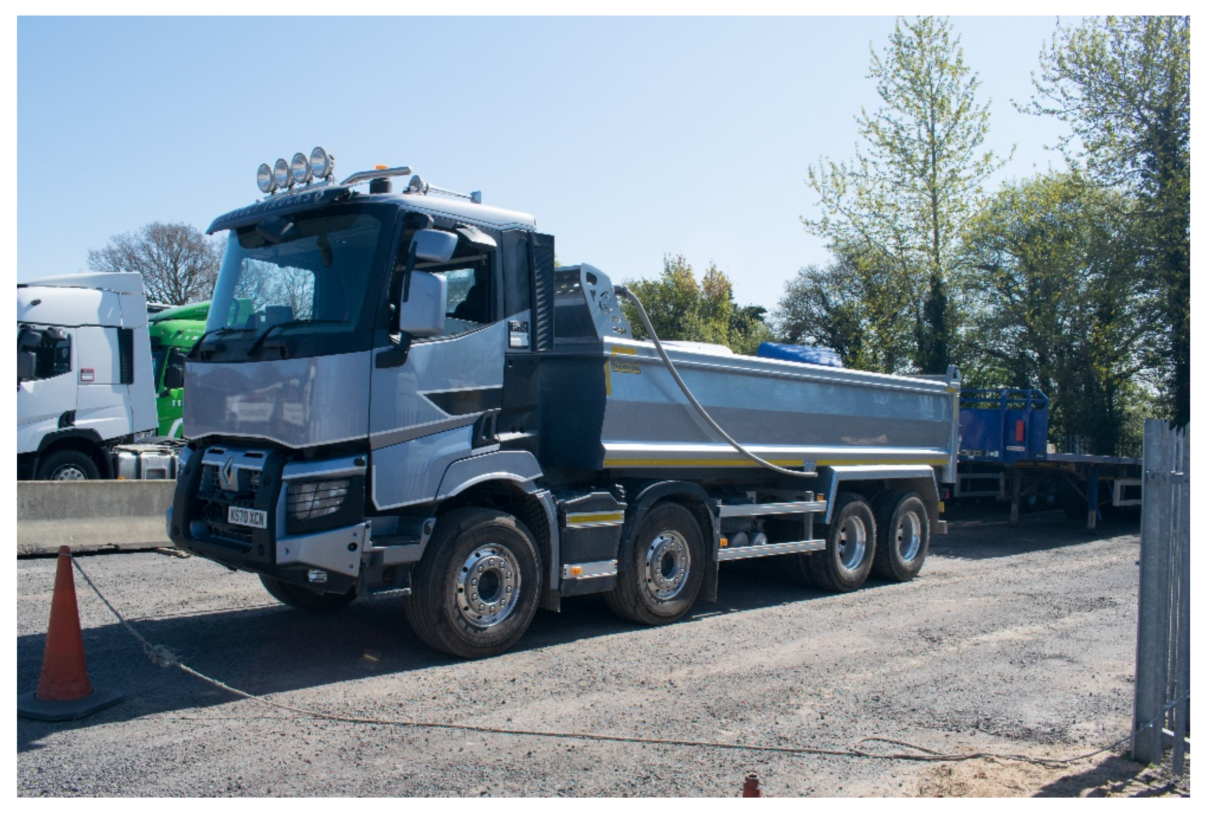
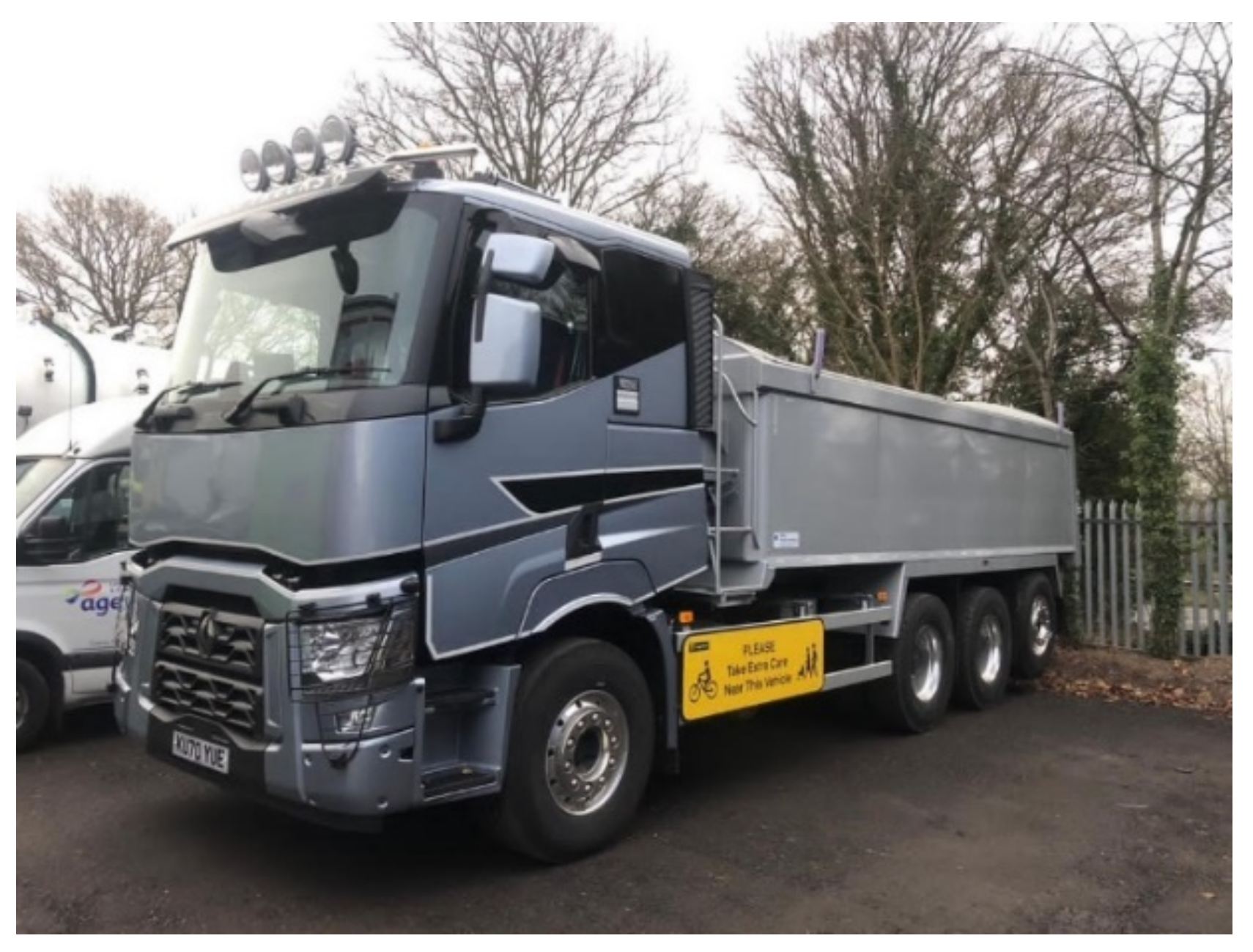
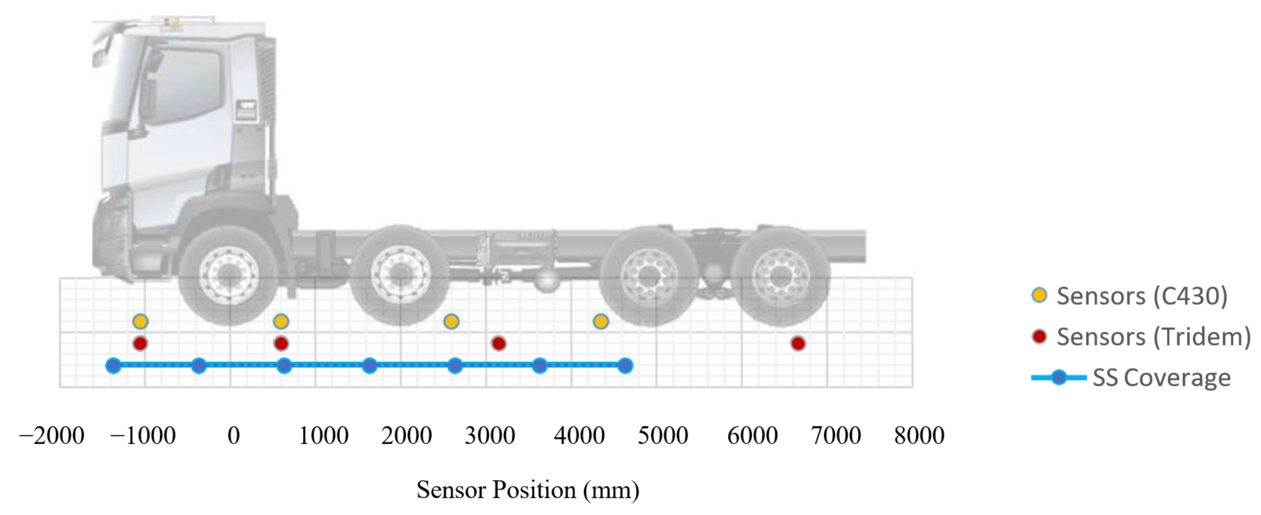
One method to combat the blind spots in side sensor systems would be to install further devices along the coverage area, with overlaps to ensure 100% coverage. However, this would result in an increased cost, and there is also the issue of locating a device within the chassis of the vehicle. HGVs are inherently different to passenger cars due to the nature of their operation and the variety of tasks they complete. Different axle configurations, bodies and accessories, coupled with the fact that most devices are fitted by a third party post vehicle manufacture, make it difficult to define a technical requirement for locations of sensors. As an example, there was a disparity observed between the fitment positions of sensors on the test and comparison vehicles in this study. This difference between the two vehicles likely alters the detection performance of each vehicle, with subsequent blind spots being removed or produced.
  • Sensor Calibration
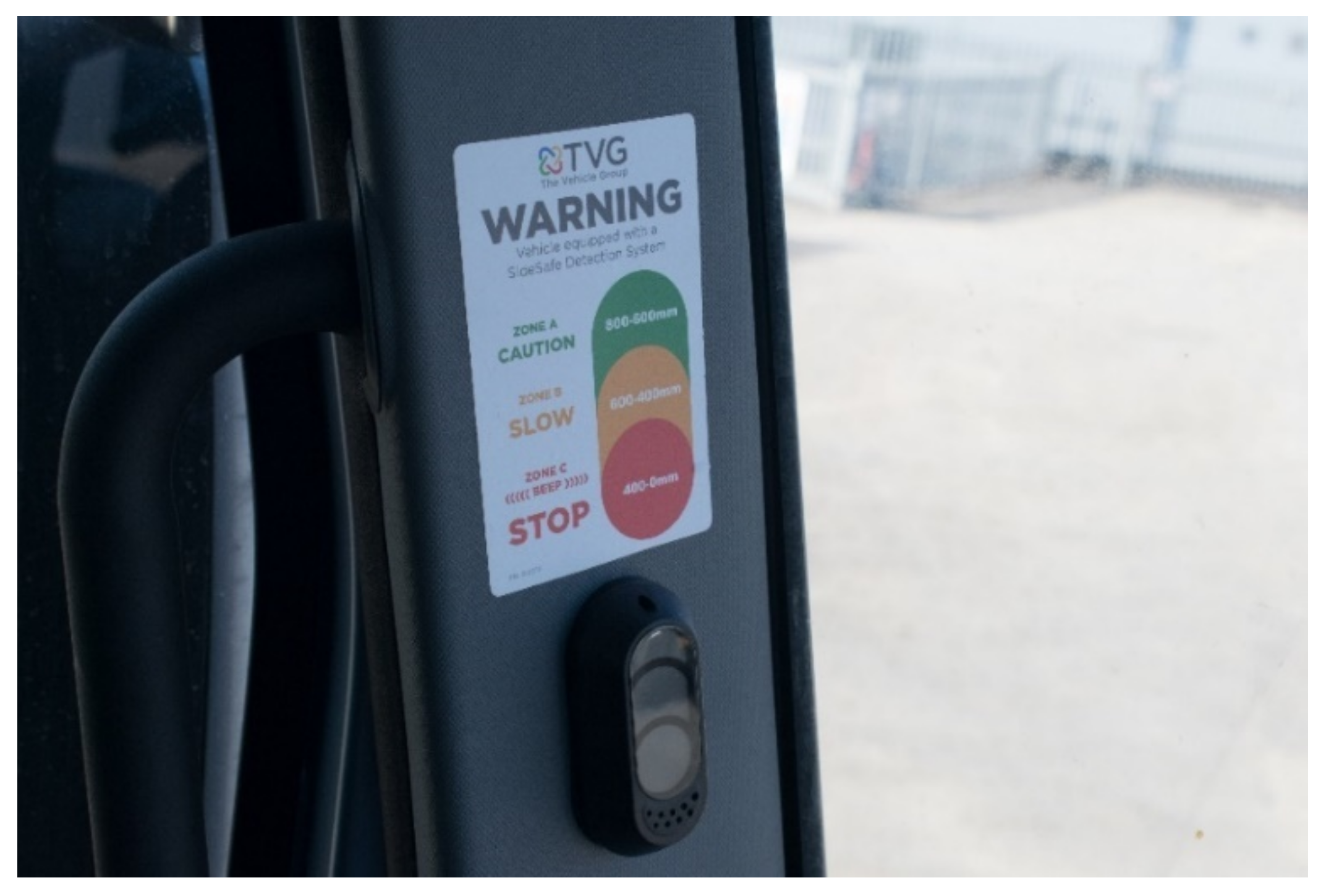
The issues with sensor coverage on the nearside might be addressed by upgrading and standardising the sensor performance and location requirements within the Safe System guidelines. There is disparity between different sensor manufacturers regarding calibration distance at which the sensors will register a red/amber/green light, and there is no specific type approval or legislative requirement for this performance. Alternative products were found to report activation at up to 2.5 m away with the transition occurring every 0.5 m [19], in contrast to the system analysed here implementing detection up to 0.8 m away and transitioning every 0.2 m. This inconsistency is concerning as certain systems/vehicles may be operating at a shorter distance than others, only detecting VRUs when they are closer to a collision, even though they all meet the Safe System guidelines.
  • Sensor Technology
Recent research [20] has suggested that sensors represent a far greater opportunity to enhance the safety of VRUs than amendments to cab design. The conclusion is, however, based on the use of a 360° detection system with the activation effectiveness of an Original Equipment (OE) Automatic Emergency Braking System (AEBS) in defining sensor reliability, rather than the simpler aftermarket systems specified for the Safe System. These OE systems can harness the vehicle’s onboard computer power for image processing, but even with these systems, reliable VRU detection still poses a challenge. A pedestrian detection algorithm based on the fusion of measurements from multiple Lidars has been proposed to improve reliability [21], yet the developers admit that detection accuracy still declines in harsh environments and when the pedestrian is partially occluded. The use of deep learning algorithms to deal with the occlusion issue is showing promise, as these algorithms essentially identify a pedestrian using less information [22]. However, these advanced systems need to be factory-fitted, while the rationale behind the Safe System is to allow HGV access to London based on the fitment of aftermarket sensors.

5. Conclusions

Heavy goods vehicles continue to require access to city centres for the delivery of goods. The current levels of vulnerable road user casualties after interaction with an HGV are not sustainable in any transport system, and especially not in those working toward Vison Zero. An additional concern is that numbers of vulnerable urban road users will increase as transport systems become “greener”. In these respects, any efforts to improve the interaction and reduce casualties can only improve sustainability of the transport system. The test program developed for this research provided valuable insight into the performance of a nearside VRU sensing system installed to TfL Safe System specifications.
  • The VRU sensing system displayed a large number of blind spots. Overall, it was only able to detect a small pedestrian surrogate in 48% of the nearside target area. In terms of levels of urgency, 56% of “stop” vehicle nodes, 45% of slow vehicle nodes and 48% of “proceed with caution” nodes were not detected. It may be necessary to specify and test the operational range for the side sensors to encourage more complete coverage. Perhaps the nearside sensors could be required to give complete coverage of the area covered by the class V mirror as specified in UN regulation 46 [13].
  • The most forward sensor missed 68% of desired “stop vehicle” nodes ahead of the front axle. Since this is an important blind spot, the current recommendation to fit additional front sensors with coverage of the class VI mirror zone might be usefully changed into a requirement.
  • Comparison of sensor positioning on two different types of HGVs showed a disparity between fitment positions, which could influence system performance, despite both meeting Safe System requirements. Specifying an operational sensor range might result in more consistent performance between vehicles, although the practicalities of sensor placement on different types of HGV chassis could be a difficult factor to overcome.
  • Sensors from two different manufacturers showed a large difference in activation range and transition distance. This could significantly influence detection accuracy even though both systems met the Safe System requirements. A tighter definition of sensor performance parameters might be required.
  • More sophisticated OE sensor systems could be specified to get around the shortcomings of standard ultrasonic sensors, but this would negate the advantages of an add-on aftermarket system, which allows city access for older designs of HGV.

Limitations and Future Research Directions

  • Test detection performance for a wider range of VRUs—nearside detection tests were carried out using an object representing the height of a small Italian female. This was chosen to represent a worst-case detection scenario and is a sensible starting point since research suggests that smaller pedestrians are more difficult to detect [23]. However, using only the smallest pedestrian could portray only the lowest detection performance of the system. In future work, it is therefore recommended that a range of pedestrian sizes be assessed, and that the system effectiveness in detecting bicycles is also examined. Ultimately, it may be possible to create moving objects to refine the analysis still further and better represent a real-life scenario.
  • Assess sensor accuracy on a wider range of HGVs—the research showed that two different HGVs, both meeting the TfL sensor fitment requirements, demonstrated significant differences in positioning of some sensors. Since this is likely to result in varying sensor performance, testing a wider variety of HGV chassis types is recommended to determine whether a more stringent sensor positioning framework is required. The vehicles available for assessment were solely rigid vehicles. The TfL Safe System covers both rigid and articulated vehicles, representing a challenge in detection during trailer articulation, with potential false positives from a vehicle’s own trailer. The test programme developed should also be applied to articulated vehicles fitted with the Safe System equipment under both “neutral” and steered positions.
  • Test a wider range of sensor systems—findings suggest that different sensor suppliers use a wide range of sensor calibration, all of which satisfy the Safe System standards, and that this could result in varying levels of performance. It is therefore recommended that more systems are tested in order to gain a better picture of the range of performance that may ensue and help determine whether a more tightly defined set of system performance parameters is required.
  • Assess detection in a wide range of weather conditions—the sensor system assessment was made in good weather, with no precipitation and with an average temperature of 16 °C. Systems should be operational across a wide range of conditions, so future testing under rain, snow and extremes of temperature both hot and cold is recommended. Very recent research [24] suggests that even the most modern pedestrian and vehicle detection systems need to be improved for use in difficult light and weather conditions.
  • Assess performance of the Automatic Emergency Braking systems—Since the front blind spot may not be fully protected through measures included in the Safe System, it would be beneficial to test the performance of the fitted AEBS that should support this coverage. Tests similar to the 2021 EuroNCAP LCV tests could be conducted on larger-category vehicles.

Author Contributions

Conceptualization, R.J.F. and J.E.M.; methodology, J.E.M.; analysis and investigation, R.J.F. and J.E.M.; writing and original draft preparation, R.J.F. and J.E.M.; writing, review and editing, R.J.F.; supervision, R.J.F.; funding acquisition, J.E.M. All authors have read and agreed to the published version of the manuscript.

Funding

This research received no external funding.

Institutional Review Board Statement

Not applicable.

Informed Consent Statement

Not applicable.

Data Availability Statement

Not applicable.

Conflicts of Interest

The authors declare no conflict of interest.

References

  1. Volvo Trucks Accident Research Team. Volvo Trucks Safety Report 2017. Available online: https://www.volvogroup.com/content/dam/volvo-group/markets/master/about-us/traffic-safety/Safety-report-2017.pdf (accessed on 13 February 2022).
  2. Summerskill, S.; Marshall, R.; Paterson, A.; Reed, S. Understanding Direct and Indirect Driver Vision from Heavy Goods Vehicles; Summary Report Prepared on Behalf of Transport for London; Loughborough University: Loughborough, UK, 2015. Available online: https://content.tfl.gov.uk/understanding-direct-and-indirect-vision-in-hgvs-full-technical-report.pdf (accessed on 13 February 2022).
  3. Marshall, R.; Summerskill, S.; Lenard, J. The Analysis of UK Road Traffic Accident Data and its Use in the Development of a Direct Vision Standard for Trucks in London. In Proceedings of the Applied Human Factors and Ergonomics (AHFE 2019), Washington, DC, USA, 24–28 July 2019; pp. 427–439. [Google Scholar] [CrossRef]
  4. European Union. Directive 2003/97/EC of the European Parliament and of the Council of 10 November 2003, on the approximation of the laws of the Member States relating to the type-approval of devices for indirect vision and of vehicles equipped with these devices, amending. Off. J. Eur. Union 2003, L 308, 15–18. Available online: https://eur-lex.europa.eu/legal-content/en/ALL/?uri=CELEX%3A32003L0097 (accessed on 15 February 2022).
  5. European Union. Regulation (EC) No 661/2009 of the European Parliament and of the Council of 13 July 2009 concerning type-approval requirements for the general safety of motor vehicles, their trailers and systems, components and separate technical units. Off. J. Eur. Union 2009, L 200, 1–24. Available online: https://eur-lex.europa.eu/legal-content/EN/ALL/?uri=celex%3A32009R0661 (accessed on 15 February 2022).
  6. European Union. Commission Regulation (EU) No 347/2012 of 16 April 2012 implementing Regulation (EC) No 661/2009 of the European Parliament and of the Council with respect to type-approval requirements for certain categories of motor vehicles with regard to advanced emergency braking systems. Off. J. Eur. Union 2012, L 109, 159–175. Available online: https://eur-lex.europa.eu/legal-content/EN/TXT/?uri=CELEX%3A32012R0347 (accessed on 17 February 2022).
  7. Euro NCAP Commercial Van Safety. 2021. Available online: https://www.euroncap.com/en/vehicle-safety/safety-campaigns/2021-commercial-van-safety/ (accessed on 13 February 2022).
  8. Transport for London. Casualties in Greater London during 2017 Factsheet. Available online: https://content.tfl.gov.uk/casualties-in-greater-london-2017.pdf (accessed on 13 February 2022).
  9. Transport For London. Vision Zero Action Plan, London. 2018. Available online: http://content.tfl.gov.uk/vision-zero-action-plan.pdf (accessed on 13 February 2022).
  10. Knight, I.; Dodd, M.; Robinson, B.; Ainge, M. HGV Safety Permit for London. Evidence of Effectiveness and Candidate Technical Requirements for the Safe System. AVS Research Report Prepared for Transport for London. 2018. Available online: https://static1.squarespace.com/static/5c877881840b16e2cb2c5150/t/5ca5d3ebe79c704398231cdd/1554371573120/HGV+Safety+Permit_Evidence+of+Effect+and+Candidate+Technical+Requirements_1_0.pdf (accessed on 13 February 2022).
  11. Transport for London. HGV Safety Permit Guidance for Operators Entering London. 2019. Available online: https://content.tfl.gov.uk/hgv-safety-permit-guidance-for-operators-entering-london.pdf (accessed on 13 February 2022).
  12. National Statistics–Road Traffic Estimates in Great Britain: 2020. Available online: https://www.gov.uk/government/statistics/road-traffic-estimates-in-great-britain-2020 (accessed on 14 February 2022).
  13. Publications Office of the EU, Regulation No 46 of the Economic Commission for Europe of the United Nations (UNECE)–Uniform Provisions Concerning the Approval of Devices for Indirect Vision and of Motor Vehicles with Regard to the Installation of These Devices. 8 August 2014. Available online: https://op.europa.eu/en/publication-detail/-/publication/780cbf09-1ec1-11e4-8c3c-01aa75ed71a1 (accessed on 13 February 2022).
  14. TVG. Direct Vision Standard Safety Equipment, SideSafe–Blind Spot Sensors. Available online: https://www.thevehiclegroup.com/solutions-for-fleets/ (accessed on 12 February 2022).
  15. Summerskill, S.; Marshall, R.; Paterson, A.; Eland, A.; Lenard, J.; Reed, S. Definition and Testing of a Direct Vision Standard for Trucks–A Physical Test to Supplement the Virtual DVS Method. 2019. Available online: https://wiki.unece.org/download/attachments/78742436/VRU-Proxi-09-04%20%28TFL-LDS%29%20UNECE%20VRU%20PROXY%20-%2026-3-19%20-%20TfL%20LDS%20combined%20presentation%20Final.pptx?api=v2 (accessed on 14 February 2022).
  16. Marshall, R.; Summerskill, S. An objective methodology for blind spot analysis of hgvs using a dhm approach. In Proceedings of the 21st International Conference on Engineering Design (ICED 17) Vol 8: Human Behaviour in Design, Vancouver, BC, Canada, 21–25 August 2017; pp. 379–388. [Google Scholar]
  17. Cook, S.; Summerskill, S.; Marshall, R.; Richardson, J.; Lawton, C.; Grant, R.; Bayer, S.; Lenard, J.; Clemo, K. The Development of Improvements to Drivers’ Direct and Indirect Vision from Vehicles-Phase 2; AR6239, Department for Transport, Jan; Loughborough University: Loughborough, UK; MIRA Limited: Nuneaton, UK, 2011; Available online: https://repository.lboro.ac.uk/articles/report/The_development_of_improvements_to_drivers_direct_and_indirect_vision_from_vehicles_-_phase_2/9341768 (accessed on 14 February 2022).
  18. Li, G.; Li, S.; Zou, R.; Liao, Y.; Cheng, B. Detection of road traffic participants using cost-effective arrayed untrasonic sensors in low-speed traffic situations. Mech. Syst. Signal Process. 2019, 132, 535–545. [Google Scholar] [CrossRef] [Green Version]
  19. Brigade Electronics, New Ultrasonic SideScan®Flex. Available online: https://brigade-electronics.com/new-ultrasonic-sidescanflex-has-arrived/ (accessed on 14 February 2022).
  20. Martin, P.; Knight, I.; Hunt, R.; O’Connell, S.; Cuerden, R.; McCarthy, M.; European Commission, Directorate-General for Internal Market, Industry, Entrepreneurship and SMEs. Study on Enhanced Truck Front End Designs (TFEDs)–Safety Benefits for Vulnerable Road Users (VRUs): Final Report, Publications Office. 2017. Available online: https://data.europa.eu/doi/10.2873/170192 (accessed on 13 February 2022).
  21. Tao, W.; Jun, H.; Lei, Y.; Kai, D. A pedestrian detection algorithm based on score fusion for multi-LiDAR systems. Sensors 2021, 21, 1159. [Google Scholar] [CrossRef]
  22. Chen, N.; Li, M.; Yuan, H.; Su, X.; Li, Y. Survey of pedestrian detection with occlusion. Complex Intell. Syst. 2021, 7, 577–587. [Google Scholar] [CrossRef]
  23. American Automobile Association. Automatic Emergency Braking with Pedestrian Detection. October 2019. Available online: https://www.aaa.com/AAA/common/aar/files/Research-Report-Pedestrian-Detection.pdf (accessed on 14 February 2022).
  24. Galvao, L.; Abbod, M.; Kalganova, T.; Palade, V.; Huda, M.N. Pedestrian and Vehicle Detection in Autonomous Vehicle Perception Systems—A Review. Sensors 2021, 21, 7267. [Google Scholar] [CrossRef] [PubMed]
Figure 1. Renault C430 Test Vehicle.
Sustainability 14 03317 g001
Figure 2. Sensor 1 (Front).
Sustainability 14 03317 g002
Figure 3. Sensor 2.
Figure 3. Sensor 2.
Sustainability 14 03317 g003
Figure 4. Sensor 3.
Figure 4. Sensor 3.
Sustainability 14 03317 g004
Figure 5. Sensor 4 (Rear).
Sustainability 14 03317 g005
Figure 6. Renault Tridem comparison vehicle.
Sustainability 14 03317 g006
Figure 7. Sensor fitment locations for C430 (8 × 4) and Tridem vehicles in relation to front axle and required safe system coverage.
Sustainability 14 03317 g007
Figure 8. Warning lights and buzzer.
Sustainability 14 03317 g008
Figure 9. Test area—0.2 m sensor resolution over 6 m required Safe System coverage zone.
Sustainability 14 03317 g009
Figure 10. Pedestrian Target.
Sustainability 14 03317 g010
Figure 11. Marker cones placed along vehicle side.
Sustainability 14 03317 g011
Figure 12. Marker cones for testing forward coverage.
Sustainability 14 03317 g012
Figure 13. Expected Detection Map for 6 m Zone.
Sustainability 14 03317 g013
Figure 14. Actual Detection Map for 6 m Zone.
Sustainability 14 03317 g014
Figure 15. Ideal Detection Map for Forward Sensor.
Sustainability 14 03317 g015
Figure 16. Actual Detection Map for Forward Sensor.
Sustainability 14 03317 g016
Table 1. Sensor locations on Renault C430 (Ax = Axle No. x).
Sensor 1Sensor 2Sensor 3Sensor 4
Height (mm)9651100855875
Position (mm)1050 ahead A1600 Behind A1600 Behind A2750 Ahead A3
Table 2. Sensor locations on Renault Tridem (Ax = Axle No. x).
Sensor 1Sensor 2Sensor 3Sensor 4
Height (mm)96010658551000
Position (mm)1050 ahead A1600 Behind A1750 Ahead A260 Behind A4
Table 3. System detection conditions.
DistanceLightAudioRecommended Action
0 < 0.4 mRedContinuousStop Vehicle
0.4 < 0.6 mOrangeNoneSlow Vehicle
0.6 < 0.8 mGreenNoneProceed with Caution
>0.8 mNoneNoneNone
Table 4. First point of HGV contact for collisions with pedestrians and cyclists STATS-19 (2019).
ContactPedestrianCyclistBoth
N%N%N%
Front9944281912734
Offside33151394612
Nearside4721594110628
Other482145319325
TOTAL227100145100372100
Table 5. HGV manoeuvre prior to collision with pedestrians and cyclists STATS-19 (2019).
HGV ManoeuvrePedestrianCyclistBoth
N%N%N%
Going ahead other10446%3927%14338%
Slowing or stopping157%107%257%
Moving off146%128%267%
Parked115%96%205%
Turning left115%3021%4111%
Turning right104%75%175%
Changing lane to left104%21%123%
Changing lane to right104%21%123%
Going ahead right- hand bend104%43%144%
Waiting to go—Held up73%32%103%
Reversing63%00%62%
Going ahead left- hand bend52%32%82%
Data missing or out of range42%64%103%
Overtaking moving vehicle—Offside31%107%133%
Overtaking static vehicle—Offside31%11%41%
Waiting to turn left21%00%20%
Overtaking—Nearside21%43%62%
U-turn00%11%10%
Waiting to turn right00%21%20%
Table 6. Actual detection for 6 m zone.
DistanceLightExpected nActual n (Difference)
0 < 0.4 mRed6227 (−35)
0.4 < 0.6 mOrange3117 (−14)
0.6 < 0.8 mGreen3116 (−15)
>0.8 mNone62126 (+64)
Table 7. Actual detection for forward sensor.
DistanceLightIdeal nActual n (Difference)
0 < 0.4 mRed227 (−15)
0.4 < 0.6 mOrange113 (−8)
0.6 < 0.8 mGreen113 (−8)
>0.8 mNone2253 (+31)
Publisher’s Note: MDPI stays neutral with regard to jurisdictional claims in published maps and institutional affiliations.

