Abstract
Considering the controllability and high responsiveness of an energy storage system (ESS) to changes in frequency, the inertial response (IR) and primary frequency response (PFR) enable its application in frequency regulation (FR) when system contingency occurs. This paper presents a coordinated control of an ESS with a generator for analyzing and stabilizing a power plant by controlling the grid frequency deviation, ESS output power response, equipment active power, and state of charge (SoC) limitation of the ESS in a power plant. The conventional generator and FR-ESS controllers were investigated and compared. To obtain the optimal frequency and power response, an ESS-based adaptive droop control method was proposed. The proposed control strategy was developed and implemented considering the changes and limitations of the dynamic characteristics of the system, FR requirements, and an ESS using the PSCAD/EMTDC software. The simulation results showed that the proposed method was more effective than the conventional droop-control-based FR-ESS, and the effectiveness of this method was validated.
1. Introduction
Currently, ESSs, which are required to achieve stability and grid safety owing to the high penetration of renewable energy resources, have received wide attention from researchers [1]. The integration of ESSs and power reserve synchronization is an effective solution for overcoming renewable energy source (RES) intermittency and fluctuating effects. This is supported by the IEC T120 work program objectives, which identify ESSs as a solution that can efficiently deliver sustainable, economic, and secure electricity supplies [2].
The importance of frequency regulation (FR) in power systems cannot be overemphasized. FR can be achieved via three distinct control stages: primary (inertial response), secondary (governor response), and tertiary (automatic generation control (AGC) [3]. An imbalance in the supply and generation at the power-grid level causes frequency deviation. An increase in the utility grid frequency can be caused by excessive power generation, which in turn increases the speeds of rotating machines, whereas a lack of supply leads to a frequency decrease. When there is a significant deviation from statutory limits, generation plants and loads are disconnected from the network, which can lead to blackouts [4]. Therefore, to maintain the desired frequency (either 60 or 50 Hz) by the grid, the total generation should be equal to the system loads and electrical losses [5]. Although low-frequency fluctuations can be handled by generator participation in secondary frequency control, the capability of these generators for high-frequency load fluctuations may not be adequate owing to the requirements of these fluctuations [6]. Therefore, ESS application for FR has a faster (quick) response, is less expensive, has a lower capacity in power plants, and offers a precise control capability over many conventional generators [7,8]. The flexibility and rapid control of the charge and discharge capabilities of ESSs to regulate the system frequency not only improves the FR performance, but also reduces the reserve of traditional units [9]. However, the use of only ESS for FR would require large storage capacity and energy, which is economically expensive [6,10]. The use of ESSs in traditional power plants initially designated for FR can therefore increase the overall efficiency of the power system [11].
Traditionally, grid operators engage with the governor-free operation of thermal power systems or generators for FR in large-scale operations. However, such generators are subjected to stress through the mechanical regulation of valve openings to compensate for FR [3]. For instance, in Korea, FR is performed using a governor-free control method with turbine governors responding within 10 s by providing power for 30 s, and the AGC responds within 30 s by providing power for 30 min. However, power plants using these approaches operate below their rated capacity to provide FR services until they are needed, making them inefficient [11,12]. Studies have been conducted concerning improving the frequency response characteristics in power systems, but little has been done to cater to the power response and SoC management of the ESS. In [13], ESS de-loading or curtailment of generation units, load-demand side management, and utilization of kinetic energy reserves have been highlighted as methods in which virtual inertia implementation can provide frequency regulation in relation to the inertial response. Reference [14] proposed a droop control strategy as a frequency regulation method for a microgrid using an ESS to regulate the ESS output power. Furthermore, ESS participation in primary frequency regulation uses both virtual droop control and virtual inertial control, which could increase the frequency nadir and effectively reduce the rate of change of frequency (RoCoF) [15]. Reference [9] proposed a control strategy in which virtual inertial and virtual negative inertia control methods were implemented to prevent frequency deterioration and accelerate frequency recovery, respectively, for ESS participation in primary frequency control (PFC). Another previous study [16] proposed droop control for battery energy storage system (BESS) participation in system-grid FR by adjusting the BESS output according to the fixed sagging coefficient. In a different study [17], a BESS based on virtual droop control was implemented to provide grid-frequency stability. However, these control strategies do not consider the limitations of the system characteristic dynamics and frequency variation requirements. A previous study demonstrated the advantage of using an ESS to replace the governor in a synchronous generator from the perspective of the SoC management scheme and FR performance. However, this study did not compare the proposed method with a conventional FR-ESS system [18].
In this study, to ensure the effect of contingency events on frequency regulation while also considering the importance of ESS-SoC management, an adaptive droop control strategy of the ESS instead of the governor is proposed. Considering the inertia value of the participating generators as the control quantity, an adaptive droop controller for the FR-ESS was designed using an algorithm to allocate the ESS output. Adjustment of the droop constant of the ESS improves the output power injected based on the frequency deviation rate for the ESS such that it may participate in primary frequency regulation. Therefore, the ESS reserves can be optimally utilized to improve the RoCoF and increase the frequency nadir, thereby improving the frequency stability of the power network. In addition, the mutual influence between the conventional generator controller and FR-ESS controller was investigated to evaluate the grid frequency response dynamics. To investigate the technical impact of this system on the overall system network, the complete test system was comprehensively modeled using electromagnetic transient analysis software (PSCAD/EMTDC). PSCAD/EMTDC is a widely used power system transient analysis tool that has intuitive simulation and modeling tools that are greatly enhanced by its state-of-the-art graphical user interface [19]. The effectiveness of the proposed control strategy was verified by simulation under the condition of a generator and load tripping disturbance.
2. Power System Architecture
2.1. Test System Model
The power system network shown in Figure 1 is considered to validate the effectiveness of the proposed method in accessing the frequency regulation response, generator output power, power grid output, and output active power of the ESS, and SoC limitations. The electrical architecture of the tested power system consists of two generators: Gen 1 (trip generator) and Gen 2 (with and without governor operation) with rated capacities of 100 and 612 MVA, respectively, and a utility grid connected to the main transformer (610.4 MVA) via a 345 kV AC bus. The ESS was installed on the 6.9 kV AC bus via an interconnection transformer (63 MVA) at the point of common coupling (PCC) with a rated capacity of 25 MW/6.25 MWh. At the PCC, the ESS terminal voltages synchronized with the system voltage can be measured appropriately. Generally, an ESS comprises a power conversion system (PCS) for DC-to-AC output conversion and a storage medium. The total load capacity of 1650 MW/315 MVAR, which consists of load A (1500 MW/300 MVAR) and load B (150 MW/15 MVAR), was connected to the 22 kV bus. Load B is the trip load. In this study, the generator was modeled as a synchronous machine in PSCAD, where the governor, exciter (ST4B), power system stabilizer (PSS2B), and turbine models were included for a more realistic simulation. Figure 1 shows the three-bus network, single-line model used for the simulation of the test results. The system parameters used for the design and simulation process are listed in Table 1.
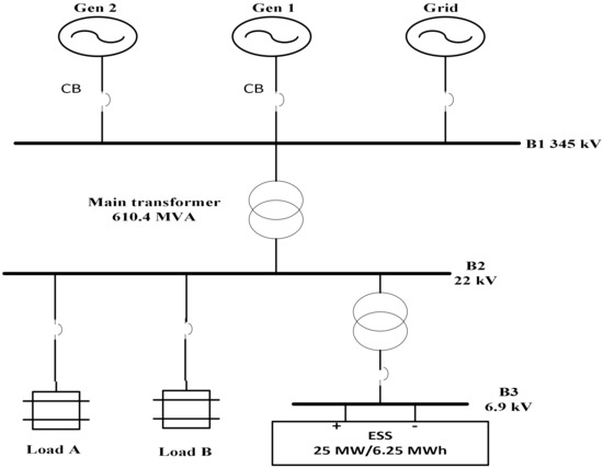
Figure 1.
Single-line diagram of the power system.

Table 1.
System Parameters.
2.2. ESS Modeling and Control Scheme
The ESS modeled in this study, which is an inverter-based reserve (IBR) system as described in Section 2, was designed such that it can inject and/or supply or absorb a certain amount of energy over a given period. The ESS structure shown in Figure 2 consists of a DC source composed of battery banks, DC link capacitors, a three-phase pulse-width modulation (PWM) inverter, inductors, and capacitor (LC) filters. The three-phase inverter is controlled using an active power/reactive power (P/Q) controller.
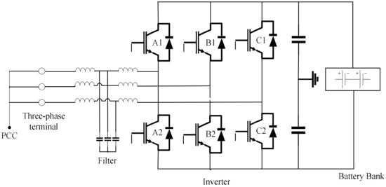
Figure 2.
Energy storage system structure [15,20].
2.2.1. Voltage Source Inverter Model
The most commonly used inverter type is the VSI, where the AC power provided on the output side functions as a voltage source. The input DC source voltage is usually an independent source, such as a battery, which is referred to as a DC-link inverter. This structure is the most widely used because it naturally behaves as a voltage source and is employed in many industrial applications. Compared with single-phase VSIs used in low-range power applications, three-phase VSIs are implemented in medium- to high-power applications.
VSIs are required in island or autonomous operation to keep the voltage stable. In microgrid applications, VSIs have been found to be interesting because they do not require any external reference to remain synchronized. The model is convenient as it provides performances such as ride-through capability and power quality enhancement to distributed power generation systems. VSIs can change behavior from voltage to current sources when they operate in grid-connected mode. This source inverter is often connected to energy storage devices to regulate both frequency and voltage in low-inertia grids. Therefore, in this study, the use of VSI drives is more efficient than current source inverters (CSI); VSI drives are distinctive for their use of insulated gate bipolar transistors (IGBTs) with fast switching times that create a PWM voltage output with regulated frequency and voltage. By contrast, CSIs use gate turn-off thyristors (GTOs) or symmetrical gate commuted thyristors (SGCTs) that generate PWM output with regulated frequency output current with high harmonics, which necessitates filters on both input and output sides. VSIs are implemented in this study because the active and reactive power can be controlled independently, thereby reducing the need for reactive-power compensation. They contribute to the stabilization of the AC network at PCC. Hence, they have the capability of better sustaining the PCC voltage.
The voltage source inverter (VSI) in this study uses the classic active power (P) and reactive power (Q) control method, also referred to as P/Q control, which was developed based on IGBT semiconductor switches, as shown in Figure 2. Figure 2 shows a schematic of a three-phase VSI interacting with energy storage and an AC system. It is connected to the AC system through line filters composed of parallel inductors and capacitors. In this inverter, three-phase reference voltages are generated using the sinusoidal pulse-width modulation (PWM) technique, as depicted in Figure 3.
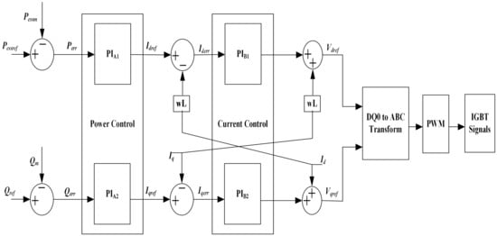
Figure 3.
Active and reactive power (PQ) control scheme.
2.2.2. P/Q Control Scheme
The ESS control strategy proposed in this study is the P/Q control scheme designed in the PSCAD/EMTDC simulation program. This system, which is depicted in Figure 3, consisted of two cascaded control loops (outer slow power control and inner fast current control). The energy management system of the ESS provided both the ESS active power reference and reactive power , which were dependent on the ESS state and load balance in the outer control loop. By contrast, the inner control loop independently controlled the direct-axis and quadrature-axis current references. To implement these control loops, proportional and integral (PI) controllers were used. The P controller regulated ESS output power in accordance with the power reference generated from frequency controller . The ESS AC side output power measured was fed into the P controller to calculate the error , which the PI controller used in generating the reference for d-axis current regulation. This controller output was regulated within the minimum ) and maximum ) d-axis current value through tuning of the PI gain parameters; this minimized frequency drop or rise and settling time. This PI controller gain parameters ( and ) values presented in the paper were obtained via the tuning rule of Ziegler and Nichols based on a measured step response to compensate single input, single output (SISO) process with time delay that satisfied both robustness and performance requirements by eliminating steady state error and reducing the overshoot with oscillations to obtain an improved transient response. The measured voltages and at each terminal of the control scheme were transformed from the DQ0 rotating frame to ABC using the Park transformation. The three-phase voltage reference signal of the PWM was determined. The reactive power reference was set by considering the droop rate. The outputs and Q of the inverter were adjusted using the droop coefficients [21]. The proportional and integral controller gains are presented in Table 2.

Table 2.
PI Controllers’ Gain.
3. Proposed Control Strategy Implementation
In this section, the proposed ESS control strategy and its structure are discussed. The control implementation is based on the regulation of the active power of the ESS and generator without the governor based on the frequency deviation rate. The power-frequency control of the ESS in relation to the system inertia for improving the stability of the power system is discussed.
3.1. System Frequency Dynamics
The nominal frequency of the Republic of Korea is 60 Hz, with a deadband of 0.2 Hz. Therefore, a frequency variation within the 59.8 to 60.2 Hz range shows that the system is in steady state. Frequencies outside of this range are regarded as abnormal owing to a contingency event [22]. In this study, the deadband of the system frequency was set to 60 ± 0.2 Hz. The change in the power system frequency can be defined by the swing equation as follows [3]:
where () represents the power deficit, which is the difference between the generation unit active power () and load demand power (), is the rated capacity of the system, is the inertia constant of the system, is the nominal frequency, and is the RoCoF.
The frequency nadir and RoCoF are emphasized in [15] as important elements to consider for system stability. Therefore, in this study, two essential elements related to the frequency response were examined: the RoCoF and inertia constant (). The inertia constant of the synchronous generator (SG) is expressed in Equation (2) [3]:
where the inertia constant of the individual generator and nominal rating of the generator are and , respectively. A block diagram of the FR-ESS control strategy used in this study is shown in Figure 4. The three-phase ESS’s current () and voltage () at the PCC are measured by the measurement block. The -axis and -axis of the currents () and voltages () are provided by the calculation block using the phase angle () derived from the phase-locked loop (PLL). The and are the inputs to the current and power controllers while the output of these controllers are and The inverter voltages () generated are sent to the PWM block as shown in Figure 4.
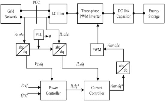
Figure 4.
Block diagram of the ESS control in the PQ mode.
3.2. Generator Modeling Dynamics
In conventional power system networks, the role of the SG is to convert mechanical energy into electrical energy, which is coupled to the prime movers (steam turbines, as used in this study) that drive the rotor. The generator’s rotor with a rotating mass contributes not only to the generator’s active power output, but also adds an inertia property to the grid frequency via the supply of its stored kinetic energy when a contingency occurs. The dynamics of the SG rotor can be expressed as in Equations (3) and (4), where Equation (4) is similar to the swing equation described in Equation (1) [23].
Here, is the mechanical torque exerted by the steam turbine; is the electrical torque exerted by the system load; is the moment of inertia; is the angular acceleration or retardation; and is the synchronous angular velocity.
To represent Equation (4) in real power terms rather than in torques using the relationship , it can be expressed as:
where and are the mechanical power input and electrical power output, respectively.
The inertia present in the SG also contributes to the effect of the RoCoF. The higher the inertia, the slower the RoCoF, and vice versa. Therefore, the mismatch between the active power and RoCoF of the grid network can be expressed as:
where is the inertia coefficient.
An imbalance in the power network causes the rotor to speed up or down to offset the power mismatch, which is a characteristic of all SGs. This response, termed the inertial response (IR) if adopted only for FR, will support the system for a few seconds; thus, the stored kinetic energy will be consumed, resulting in system collapse. Therefore, a droop or PFC scheme mainly provided by SG governors was employed to adjust the generator output power in response to the grid frequency variation. In this study, the damping term was considered while modeling the SG, which was provided by the quadrature axis damper windings set at a value of two to resolve the spikes in voltage as a result of sudden disturbances. Therefore, with the incorporation of the damping term, the swing equation of the SG is:
where is the damping coefficient of the generator.
3.3. Proposed Adaptive Control Method
Figure 5b,c depict the simplified and detailed proposed method of the FR-ESS with a generator, respectively. In the configuration shown in Figure 5b, the generator operated without a governor and the ESS was activated, whereas in Figure 5a, the governor regulated the angular speed of the SG. The governor adjusted the mechanical power ) with respect to the angular velocity variation of the generator rotor. As shown in the detailed representation in Figure 5c, the ESS was interfaced with the proposed adaptive control scheme, which functioned as PFC. During a contingency event, the generator output power changed and the ESS proposed in this study compensated for a power deficit by providing active power through the PCC to contribute to the FR. The main goal of the proposed adaptive control scheme is to enhance frequency regulation by reducing the RoCoF and frequency deviation.
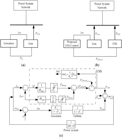
Figure 5.
FR with/without the ESS and governor: (a) conventional and (b) proposed system. (c) Proposed adaptive control of ESS operation with a synchronous generator for FR and SoC calculation.
In the proposed configuration method, droop control of the FR-ESS, characterized as a power converter, was used by the generator without the governor owing to its fast action. The system frequency deviation served as the input in the ESS control block, in which the ESS executed the droop control by adaptively adjusting the electrical power (). The droop control block ) generated an output signal . In other words, the adaptive droop control of the ESS was the product of the inverse droop rate and frequency deviation, which determined the amount of supporting power from the ESS, which was defined as in Equations (8) and (9) for both PFC and IR regulation, respectively, following the grid-frequency variation in Equation (10). In the conventional control scheme, the ESS droop rate was set to 5% (i.e., the control coefficient was 20), whereas that of the proposed control was 1% and the corresponding inertia constant value was 4 s.
Using this method, both the IR and PFC were provided to the power system through inertia constant adjustment and power-frequency droop rate adjustment, respectively.
Here, is the change in the power output based on the droop characteristics, is the ESS droop rate value, expressed in (pu) is the frequency deviation from the contingency event, is the grid frequency, is the reference frequency, is the power required to regulate the RoCoF for the inertial response, and is the inertia constant value of the ESS for the RoCoF.
Therefore, the power of the ESS based on the droop rate () for frequency regulation is the summation of the power regulation of RoCoF () and the power output based on the droop characteristics (), which can be defined as in Equation (11). The total output of the ESS () can then be derived as in Equation (12) for FR. This differs from the conventional droop method and enables the ESS to manage its energy optimally.
Here, is the ESS power based on the droop rate for FR, is the ESS reference power, and is the total ESS output power.
For the power system network to be stable after a disturbance occurs, the total power generation should match the load demand. Therefore, the amount of power flow to the grid can be calculated from Equation (13), which should match the load demand ().
Here, is the SG active power output, is the ESS active power output, is the total load demand, and is the grid power.
Traditionally, the SoC is calculated by integrating the current (unit of current) [24,25]; however, it does not define the relationship between the battery power and SoC. In this study, we implemented the energy concept identified in [26] by integrating the power to calculate the SoC of the ESS in Equations (14) and (15) assuming that the battery’s internal voltage was kept constant (i.e., power was proportional to current). As illustrated, the ESS power and SoC dynamics were employed to establish a relationship between the change in grid frequency and the SoC limit.
Here, is the ESS-SoC [%], is the initial SoC value [%], is the ESS energy [MWs], PESS is the ESS power [MW], is the ESS size [MWh], and is the constant used to convert hours to seconds.
The SoC limitation scheme has been developed for FR-ESS applications, which involve a reference value that the ESS is continually attempting to adapt to with a set nominal frequency (60 Hz). This reference value, termed the initial SoC (), was 50% in this study, indicating the highest potential energy of charging and discharging [18]. The absorption or supply of ESS power (PESS) results in a change in the SoC. Similarly, when the ESS stops operating (i.e., it does not inject or absorb power), the SoC must remain constant.
3.4. ESS Control Algorithm
Figure 6 shows the control scheme for the FR-ESS based on the proposed methodology described in Section 3. The FR-ESS control algorithm in this study performed charging and discharging operations to reduce frequency variations by providing and/or absorbing power, which depended on the droop control signal it received. This was designed such that the proposed adaptive droop control scheme required a limit on the ESS capacity to prevent the excessive charging and overcharging of power. Therefore, the upper limit and lower limit were set appropriately. The control operation was based on the frequency deviation of the power system, which was initiated to implement droop control by adjusting the droop rate while ensuring that the ESS capacity limit was monitored when a contingency operation occurred. The ESS was activated depending on the grid-frequency deviation outside of the deadband in two modes of operation (charging and discharging). Therefore, the ESS operated in discharge mode when its active power output was greater than zero, providing power to the system, and vice versa. In idle mode, the active power was kept constant at zero. To avoid oscillation problems that may occur between the operation modes, a small deadband of 20% (the actual size of deadband can be adjusted based on the system requirements) was introduced for ESS control switching following Equations (16) and (17) for the charging and discharging modes, respectively. This deadband represented the offset frequencies and , which were 59.8 and 60.2 Hz, respectively. Therefore, a frequency variation within this range was regarded as a steady-state system. When the frequency was within the deadband, the ESS operated without charging or discharging to maintain the frequency. If the system frequency dropped below , the ESS provided power to . Otherwise, the ESS absorbed the power to charge up to . The charging and discharging amounts of the power output can be calculated using the droop rate, as shown in Equation (18). The frequency deviation can have both positive and negative values that define the ESS power injection and absorption, respectively, as expressed in Equation (10).
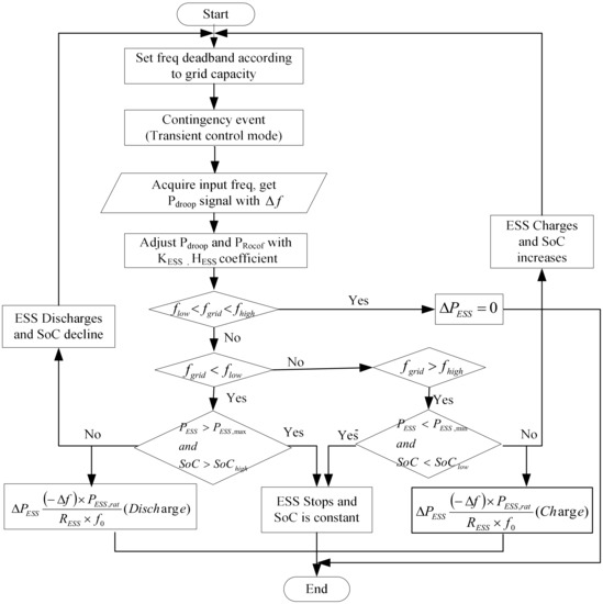
Figure 6.
Flow chart of the control algorithm of the proposed method for FR.
Here, (−25 MW) and (+25 MW) are the ESS power output charging and discharging limits, respectively; is the frequency deviation [Hz]; is the ESS output power variation [MW]; is the ESS rating [MW]; is the nominal frequency [Hz]; is the droop rate of the ESS.
In this study, the SoC limitation of the ESS was designed to operate based on the frequency deviation variation rate as well as the power output of the ESS. In most studies, an SoC reference value required to regulate the SoC of the ESS is set as a constant. This fixed value must be adjusted to avoid frequent charging and discharging of the ESS because it is not the same as the target value [27]. Therefore, in this study, the operation of the ESS was subject to the SoC range constraint to limit its output power according to the SoC and prevent the aforementioned issue when it participates in FR. The normal SoC operation range during the emergency case was (50, 80) for and , respectively. When the SoC exceeded the upper limit, the control scheme activated the discharging of the ESS, thereby reducing the SoC to prevent overcharging and vice versa when the SoC exceeded the lower limit. The operational constraints are defined in Equations (19) and (20) for normal operation and during an emergency, respectively. For the case considered in this study, a low SoC limit was investigated to compare the proposed method of ESS in PFC with the conventional method considering the rate of frequency deviation. The control mechanism involved using the droop control of the ESS to regulate the frequency variation. The control strategy can be summarized in Equation (21), which defines the charging, discharging, and idling powers (wherein both the charging and discharging powers are zero) of the ESS.
4. Simulation Analysis and Results
To verify the effectiveness of the proposed control scheme using the test system shown in Figure 1, a case study was conducted during a contingency event by tripping both generator G1 and load B to compare three different control techniques via simulation. The case study conducted using PSCAD/EMTDC is described as follows.
Case 1: Generator G2 (with governor) while the ESS is deactivated.
Case 2: Generator G2 (without a governor) with the ESS and conventional droop control.
Case 3: Generator G2 (without a governor) with the ESS and adaptive droop control.
The simulations were carried out for a duration of 50 s and generator G1 was tripped at 5 s to cause a mismatch of the power imbalance, thereby causing the system frequency to deviate. Similarly, load B was tripped at 25 s, causing the system frequency to rise above the nominal value. This frequency deviation also has a significant effect on the grid active power, participating generators, and ESS in frequency regulation. Therefore, we investigated the effect of only the governor without an ESS (Case 1), the power compensation of the ESS using the conventional droop method (Case 2), and the proposed method (Case 3) to verify its advantages.
4.1. Frequency Variation
In the Korean power system, the minimum frequency deviation is 59.70 Hz after a disturbance occurs. Figure 7 shows a comparison of the grid frequency between the governor and generator, ESS compensation with a conventional (fixed) droop, and the proposed (adaptive droop) control scheme. As depicted in Figure 7, it can be deduced that the grid frequency is at a normal value (60 Hz) before the contingency events occur. When the tripping of the generator occurs at 5 s, the grid frequency curves of the three FR control techniques decreased rapidly. It can be seen that the minimum frequency deviations (nadir) for Cases 1 and 2 are the same (59.64 Hz); however, the frequency nadir for Case 3 is 59.71 Hz. Similarly, when the load was tripped at 25 s, the frequency response of the system increased. However, the maximum frequency increase was lower with the proposed method (60.15 Hz) than in Cases 1 and 2 (60.21 Hz). This shows that the proposed method can decrease the RoCoF with an improved frequency nadir compared with both Cases 1 and 2. Therefore, FR using the proposed method is improved compared with the other control methods. A rapid change in the rotating speed of the synchronous generator, which can result from a loss in a large generating unit, can lead to an unacceptable frequency decrease or sudden disconnect in load, which may in turn result in grid frequency instability. The existing or conventional generators supply or absorb their stored kinetic energy to adapt to frequency deviations in the inertia response (IR) stage [28]. However, the responses of the conventional methods were slow compared to that of the proposed method.
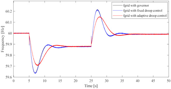
Figure 7.
Comparison of the grid frequencies using only a governor, ESS with conventional control, and ESS with the proposed method.
4.2. Active Power Output
Figure 8 and Figure 9 show the results of the grid and generator active power responses compared to the three control methods (generator with a governor and ESS with the conventional proposed methods), respectively. It can be observed that the grid active power in Figure 8 exhibits slightly better oscillation damping with the proposed control compared to the conventional method, which exhibits higher oscillations in the transient stage (5 to 10 s). In the steady-state region (0 to 5 s and 35 to 50 s), the active power supplied to the grid is the same for all control strategies.
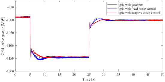
Figure 8.
Comparison of the system’s active power for the different control methods.
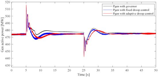
Figure 9.
Comparison of the generator’s active power for the different control methods.
The generator’s active power in Case 1 was increased during the generator tripping event (5 to 25 s) from the steady state value of 474 MW at 0 s to 477.7 MW at 20 s to compensate for the frequency drop, as shown in Figure 9. However, for Cases 2 and 3, the active power output () was the same as the steady-state value (474 MW at 20 s). This shows the effect of the governor in Case 1 for FR compared to FR-ESS in Cases 2 and 3. Although the power fluctuated during the tripping events of both the generator and load, a new steady state was reached when the frequency stabilized. The variation in the output power of the generators in Case 1 occurred because the power compensation was limited to only the kinetic energy released by the SG through the governor with respect to the droop setting. Similarly, the amount of ESS power injected into the system with fixed droop control (Case 2) and adaptive droop control (Case 3) was limited by the droop rate constant.
4.3. ESS Active Power
According to the ESS power output shown in Figure 10, the operation of the ESS in terms of the injection and absorption of power to and from the grid can be observed when the grid frequency deviates. During the generator tripping event, the frequency drops, causing the ESS participating in FR to inject power into the system. However, the amount of power is dependent on the ESS droop-rate constant. Using the proposed method, more power can be injected into the system to minimize the frequency nadir. Likewise, when the frequency increases owing to load tripping, the ESS with the proposed method has the capability to absorb more power than the conventional method. Therefore, the ESS discharges its power by injecting a proportion defined by the droop rate value in Equation (8) such that a reasonable amount of active power provides compensation for stabilizing the system. In addition, this system charges in a similar manner. When there is no change in the grid frequency (no disturbance), the ESS remains in idle mode with a power equal to zero, as depicted in Figure 10. Using the proposed method, where the ESS uses a control scheme with a lower droop-rate value compared with the conventional control method, it can provide more power to the system during the transient period while ensuring that the maximum rated power is not exceeded. Therefore, the ESS can change its active power with respect to droop control to assist with FR.
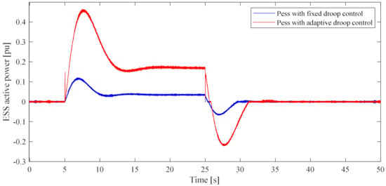
Figure 10.
Comparison of both methods for ESS active power.
4.4. SoC Response
The control algorithm flow chart in Figure 6 shows the ESS active power limit and the SoC limit relation. When the power injected by ESS reached maximum, and the SoC was close to high limit, the ESS stopped to inject power and the SoC remained constant. Similarly, when the power absorbed by the ESS reached minimum, and the SoC was close to its lowest limit, the ESS stopped to absorb power and the SoC remains constant. When the ESS active power was within limit, the SoC of the ESS could increase and decrease rapidly with the proposed control to support FR. The SoC response of the ESS active power during charging, discharging, and idling is presented in Figure 11. It can be seen from this figure that at the steady state that occurred before the contingency event (0 to 5 s), the ESS-SoC was at the initial SoC (50%). However, when the generator was tripped, causing the frequency to drop, the ESS discharged owing to the power injection into the grid to provide FR (5 to 25 s). It could be observed that, at the duration when frequency drops rapidly below nominal value (5 to 10 s), the SoC curves in Case 3 was steeper than in Case 2. This effect in SoC difference corresponds to the amount of power injected by the ESS to improve the frequency nadir of the power system. At 10 s < t < 25 s, when the grid frequency was recovering to a new steady state, the SoC response in Case 2 declined not so rapidly as compared to that of Case 3. This signifies that a small amount of ESS active power is still injected into the grid as shown in Figure 10. At t = 25 s, when load trip occurred, the SoC curves for both the conventional and proposed method reached their low limit values of 49.84% and 49.22%, respectively. Similarly, as the frequency increased above the nominal value owing to load tripping, the ESS absorbed power, thereby charging (25 to 32 s). At this point, the SoC could be seen to have increased more rapidly in Case 3 than in Case 2. At the point when the frequency became stable and neared the nominal value (38 to 50 s), the ESS-SoC new limit was reached as a result of the ESS neither injecting nor absorbing power. From Figure 11, it can be deduced that the rate of SoC decrease was higher with the proposed method as compared to the conventional method, and the opposite is observed considering the increasing SoC rate. This shows that the proposed method can inject and absorb power to and from the grid rapidly to support FR through its fast charging and discharging rate without exceeding the limit.
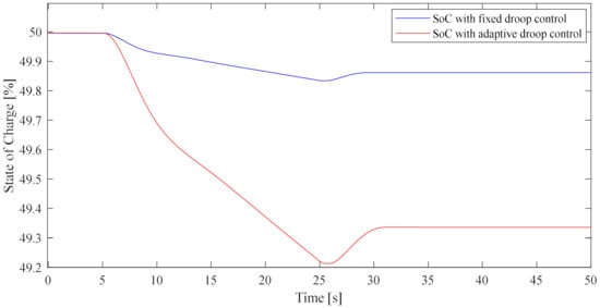
Figure 11.
Comparison of SoC operations for the conventional and proposed methods.
5. Conclusions
In this study, we proposed an adaptive control strategy to coordinate a generator with an ESS in FR. The proposed method operated using an ESS to provide FR by employing both droop control and inertia constant adjustment to improve the frequency deviation, RoCoF, and frequency nadir of the system. An ESS control algorithm was developed to assist in managing the dynamic nature of the power system for an efficient power supply to the grid to protect the system from severe frequency deviation, thereby increasing system stability. We compared case studies involving only governor control, an ESS with the conventional fixed droop method, and an ESS with the proposed adaptive droop control scheme when the power system network was subjected to contingency events. To verify the performance of the proposed method, a dynamic simulation was performed to investigate the mutual influence between the conventional generator controller and the FR-ESS controller with respect to grid frequency regulation and SoC limitation. It was observed that FR using an ESS can be more effective in contingency events (such as the non-functionality of transmission lines, generator trips, load trips, and three-phase faults) compared to the conventional generator. From the simulation results, we observed that, compared to the ESS with a fixed droop control scheme, the proposed FR-ESS controller provided the best results in regulating the frequency response by lowering the RoCoF and improving the minimum frequency deviation (higher frequency nadir) during the generator tripping event. Similarly, the frequency response amplitude was improved during the load tripping event using the proposed method. The SoC limitation was also investigated to compare the conventional and proposed methods. The result from the SoC of ESS shows that the proposed method has a faster action as compared to the conventional method in terms of charge and discharge rate without violating the SoC operating limits. The results indicated that inverter-based reserves such as ESSs respond faster to frequency deviations compared to the governor of a generating unit operating only with a conventional droop control scheme.
Considering the results presented in this study, system operators may use the proposed method to observe the effects of RoCoF based on the ESS power by changing the parameter settings according to the power plant conditions.
From the perspective of a transmission network, ESS has great potential to provide various grid stability supports. This study only focused on active power (P) and frequency control through the proposed generator with FR-ESS. In this kind of control system, the generator’s reactive power and voltage are not considered. However, for future studies where the reactive power (Q) and voltage regulation is to be explored for performance evaluation, a harmonized optimal control method in terms of Q and voltage (V) will be required. Therefore, future studies of this kind of control for both P and Q for frequency and voltage regulation, respectively, is anticipated.
Author Contributions
Conceptualization, L.O.I., I.-Y.C., J.Y., J.W.S. and M.Y.; Methodology, L.O.I., J.W.S., M.Y. and J.S.; Investigation, M.Y. and J.S.; Supervision, Y.-M.S. and M.Y.; project administration, I.-Y.C. and J.Y.; Writing—original draft preparation, L.O.I.; Review and manuscript approval, L.O.I., Y.-M.S., J.W.S., M.Y. and J.S. All authors have read and agreed to the published version of the manuscript.
Funding
This work was supported by the Korea Electric Power Corporation grant (R21XO01-1) and National Research Foundation Grant (2020R1F1A1076638) funded by the Korean government.
Institutional Review Board Statement
Not applicable.
Informed Consent Statement
Not applicable.
Conflicts of Interest
The authors declare no conflict of interest.
References
- Barelli, L.; Bidini, G.; Bonucci, F.; Castellini, L.; Castellini, S.; Ottaviano, A.; Pelosi, D.; Zuccari, A. Dynamic Analysis of a Hybrid Energy Storage System (H-ESS) Coupled to a Photovoltaic (PV) Plant. Energies 2018, 11, 396. [Google Scholar] [CrossRef]
- IEC T120. Available online: http://www.iec.ch/dyn/www/f?p=103:7:11494349307735::::FSP_ORG_ID,FSP_LANG_ID:9463,25 (accessed on 4 April 2022).
- Kundur, P.; Balu, N.J.; Lauby, M.G. Power System Stability and Control, 2nd ed.; The EPRI Power System Engineering Series; McGraw-Hill: New York, NY, USA, 1994; ISBN 0-07-035958-X. [Google Scholar]
- Timur, Y.; Maximilian, J.Z.; William, H. Control of Energy Storage. Energies 2017, 10, 1010. [Google Scholar]
- Aho, J.; Buckspan, A.; Laks, J.; Fleming, P.; Jeong, Y.; Dunne, F.; Churchfield, M.; Pao, L.; Johnson, K. A tutorial of wind turbine control for supporting grid frequency through active power control. In Proceedings of the 2012 American Control Conference (ACC), Montreal, QC, Canada, 27–29 June 2012; IEEE: Piscataway, NJ, USA, 2012; pp. 3120–3131. [Google Scholar]
- Pan, X.; Xu, H.; Lu, C.; Song, J. Energy storage system control strategy in frequency regulation. In Proceedings of the 2016 IEEE International Conference on Automation Science and Engineering (CASE), Fort Worth, TX, USA, 21–26 August 2016; IEEE: Piscataway, NJ, USA, 2016; pp. 664–669. [Google Scholar]
- Castillo, M.D.; Lim, G.P.; Yoon, Y.; Chang, B. Application of Frequency Regulation Control on the 4 MW / 8 MWh Battery Energy Storage System (BESS) in Jeju Island, Republic of Korea. J. Energy 2015, 1, 287–295. [Google Scholar]
- Kirby, B. Frequency Regulation Basics and Trends, ORNL/TM-2004/291; Technical Report; Oak Ridge National Laboratory: Oak Ridge, TN, USA, 2005. [Google Scholar]
- Fang, C.; Tang, Y.; Ye, R.; Lin, Z.; Zhu, Z.; Wen, B.; Ye, C. Adaptive Control Strategy of Energy Storage System Participating in Primary Frequency Regulation. Processes 2020, 8, 687. [Google Scholar] [CrossRef]
- Leitermann, O. Energy Storage for Frequency Regulation on the Electric Grid. Ph.D. Thesis, Massachusetts Institute of Technology, Cambridge, MA, USA, 2012. [Google Scholar]
- Federal Energy Regulatory Commission. Frequency Regulation Compensation in the Organized Wholesale Power Markets. 2011. Available online: https//www.jonesday.com/en/insights/2011/10 (accessed on 6 June 2022).
- Lim, G.P.; Park, C.W.; Labios, R.; Yoon, Y.B. Development of the control system for fast-responding frequency regulation in power systems using large-scale energy storage systems. KEPCO J. Electr. Power Energy 2015, 1, 9–13. [Google Scholar] [CrossRef]
- Tielens, P.; Van Hertem, D. Grid inertia and frequency control in power systems with high penetration of renewables. In Proceedings of the Young Researchers Symposium in Electrical Power Engineering, Delft, The Netherlands, 16–17 April 2012. [Google Scholar]
- Dreidy, M.; Mokhlis, H.; Mekhilef, S. Inertia response and frequency control techniques for renewable energy sources: A review. Renew. Sustain. Energy Rev. 2017, 69, 144–155. [Google Scholar] [CrossRef]
- Yoon, M.; Lee, J.; Song, S.; Yoo, Y.; Jang, G.; Jung, S.; Hwang, S. Utilization of Energy Storage System for Frequency Regulation in Large-Scale Transmission System. Energies 2019, 12, 3898. [Google Scholar] [CrossRef]
- Zhang, Y.J.; Zhao, C.; Tang, W.; Low, S.H. Profit-maximizing planning and control of battery energy storage systems for primary frequency control. IEEE Trans. Smart Grid 2016, 9, 712–723. [Google Scholar] [CrossRef]
- Li, Y.; He, L.; Liu, F.; Li, C.; Cao, Y.; Shahidehpour, M. Flexible voltage control strategy considering distributed energy storages for DC distribution network. IEEE Trans. Smart Grid 2017, 10, 163–172. [Google Scholar] [CrossRef]
- Nguyen-Hoang, N.-D.; Shin, W.; Lee, C.; Chung, I.-Y.; Kim, D.; Hwang, Y.-H.; Youn, J.; Maeng, J.; Yoon, M.; Hur, K.; et al. Operation Method of Energy Storage System Replacing Governor for Frequency Regulation of Synchronous Generator without Reserve. Energies 2022, 15, 798. [Google Scholar] [CrossRef]
- Manitoba HVDC Research Centre. PSCAD/EMTDC User’s Manual Guide v.4.5; Manitoba HVDC Center: Winnipeg, MB, Canada, 2013. [Google Scholar]
- Ibrahim, L.O.; Sung, Y.M.; Hyun, D.; Yoon, M. A Feasibility Study of Frequency Regulation Energy Storage System Installation in a Power Plant. Energies 2020, 13, 5365. [Google Scholar] [CrossRef]
- Gkavanoudis, S.I.; Oureilidis, K.O.; Kryonidis, G.C.; Demoulias, C.S. A Control Method for Balancing the SoC of Distributed Batteries in Islanded Converter-Interfaced Microgrids. Adv. Power Electron. 2016, 2016, 8518769. [Google Scholar] [CrossRef]
- Oudalov, A.; Chartouni, D.; Ohler, C. Optimizing a battery energy storage system for primary frequency control. IEEE Trans. Power Syst. 2007, 22, 1259–1266. [Google Scholar] [CrossRef]
- Machowski, J.; Lubosny, Z.; Bialek, J.W.; Bumby, J.R. Power System Dynamics: Stability and Control; John Wiley & Sons: Hoboken, NJ, USA, 2020. [Google Scholar]
- Tremblay, O.; Dessaint, L.A. Experimental Validation of a Battery Dynamic Model for EV Applications. World Electr. Veh. J. 2009, 3, 289–298. [Google Scholar] [CrossRef]
- Shepard, C.M. Design of Primary and Secondary Cells. J. Electrochem. Soc. 1965, 112, 657. [Google Scholar] [CrossRef]
- Shim, J.W.; Verbič, G.; Kim, H.; Hur, K. On droop control of energy-constrained battery energy storage systems for grid frequency regulation. IEEE Access 2019, 7, 166353–166364. [Google Scholar] [CrossRef]
- Zhu, Z.; Ye, C.; Wu, S. Comprehensive control method of energy storage system to participate in primary frequency regulation with adaptive state of charge recovery. Int. Trans. Electr. Energy Syst. 2021, 31, e13220. [Google Scholar] [CrossRef]
- El-Bidairi, K.S.; Nguyen, H.D.; Mahmoud, T.S.; Jayasinghe SD, G.; Guerrero, J.M. Optimal sizing of Battery Energy Storage Systems for dynamic frequency control in an islanded microgrid: A case study of Flinders Island, Australia. Energy 2020, 195, 117059. [Google Scholar] [CrossRef]
Publisher’s Note: MDPI stays neutral with regard to jurisdictional claims in published maps and institutional affiliations. |
© 2022 by the authors. Licensee MDPI, Basel, Switzerland. This article is an open access article distributed under the terms and conditions of the Creative Commons Attribution (CC BY) license (https://creativecommons.org/licenses/by/4.0/).