Article

Experimental Research on Seismic Behavior of Haunched Concrete Beam–Column Joint Based on the Bolt Connection

1
School of Civil and Engineering, Anhui Jianzhu University, Hefei 230601, China
2
Anhui Institute of Building Research & Design, Hefei 230088, China
3
2nd Construction Co., Ltd. of China Construction 5th Engineering Bureau, Hefei 230601, China
*
Author to whom correspondence should be addressed.
Sustainability 2022, 14(23), 15644; https://doi.org/10.3390/su142315644
Submission received: 26 October 2022 / Revised: 21 November 2022 / Accepted: 22 November 2022 / Published: 24 November 2022

Abstract

:
Studying the seismic performance of assembled beam–column joints is essential for the development of assembled frame structures. In this paper, a novel dry connection beam–column joint with a high degree of modularity and a simple structure is proposed and tested using a pseudostatic test. The joint is composed of a precast concrete beam with a steel axillary plate at the end and a precast concrete column connected by long bolts. By analyzing the characteristics of the hysteresis curve, skeleton curve, and stiffness degradation curve, we were able to investigate the seismic performance of this novel new joint under low circumferential reciprocating load as well as the impact of bolts of various strength grades on the joint’s seismic performance. The results illustrated the robust overall bearing performance of the newly assembled beam–column joint. However, when connected with common bolts, the joint deforms more, exhibits good ductility, clearly displays semi-rigid characteristics, and performs better in terms of energy dissipation. This contrasts with connecting with low-strength bolts, which cause the joint to deform little and have poor energy dissipation capacity. The prefabricated columns and beams remain undamaged, making it possible to quickly repair the assembled building structure after an earthquake; however, the joints are harmed due to the bending and fracture of the connection bolts. It has been suggested that researchers add damping energy dissipation devices to the new joint to increase its energy dissipation capacity and control the joint’s overall deformation because the joint’s energy dissipation capacity is insufficient under the low circumferential reciprocating load.

1. Introduction

A significant amount of change has taken place in the traditional construction industry, which is predominantly comprised of cast-in-situ concrete structures, as a result of the ongoing advancement in building construction techniques [1,2,3,4]. The prefabricated concrete building offers the benefits of a quick construction time, high construction quality, and high resource and energy conservation, which partially satisfy modern society’s need for construction. The advantages of the prefabricated concrete frame structure include a flexible building layout, easily standardized beam and column members, a high prefabrication ratio, and a broad range of applications, making it a widely researched and used structural system in prefabricated structures. Destruction of the connecting joints is the primary cause of building damage, according to previous earthquake damage investigations. The connection of the fabricated members at the joints is therefore crucial to ensuring efficient seismic performance of the constructed concrete frame structure [5,6,7,8]. The three main connection types used today for the beam–column joint in fabricated concrete structures are bolting, grouting sleeve connection, and reinforcement welding and anchoring. Due to low mechanization, slow construction progress, and significant difficulties in quality inspection and control at the joints, these forms of connection—welding, anchoring, and grouting sleeves—possess hidden safety risks. The high ratio of fabrication, high degree of mechanization, and ease of installation are benefits of the dry connection type of bolting connection.
The bolting connection technique has received a lot of attention recently from researchers all over the world. The fabricated beam–column joints connected by bolts exhibit good mechanical behavior under a low-cycle reciprocating load and have a rapid promote-repair capability after an earthquake, as opposed to the cast-in-site joints. Finite element simulation was performed on the proposed fabricated beam–column joints by Torra-Bilal I et al. [9] before a low- cycle reciprocating loading test was used to confirm the simulation results. According to the test results, the beam–column joints that were constructed exhibit excellent mechanical behavior under a low-cycle reciprocating load. Naserabad et al. [10] discovered through experimental testing and numerical simulation analysis that the fabricated RC beam–column joints can use the connection form of bolts. Additionally, it was demonstrated through these studies that the use of bolts can significantly increase joints’ ductility, and that joints’ deformation resistance has also been somewhat enhanced. In addition, because of the bolt connection’s straightforward functionality, the construction process can advance somewhat faster. By combining the bolt connection and prestress method, LeeDong-Joo et al. [11] adopted a testing procedure in which the prestressed reinforcement was pre-embedded at the joints. It was discovered through testing on the fabricated concrete joints that this method could successfully reduce the structure’s residual deformation capacity and successfully control the crack formation at the joints. In comparison to cast-in-site joints, this type of joint consumes less energy, but its ability to control structural displacement exhibits excellent behavior. Oh et al. [12] innovatively proposed to use a beam–column joint to connect the bottom flange of the beam and the slit damping screw with a high-strength bolt. Three full-size specimens underwent a quasi-static cycle test, and the results show that this new type of beam–column joint not only has good energy consumption performance but can also be quickly repaired following a strong earthquake. In order to study the mechanical properties of such joints under low circumferential reciprocal loads, Ding et al. [13] proposed a new type of semi-dry beam–column joint and carried out experiments and finite element simulations for beam–column joint specimens. The results show that the new joints have good plastic deformation capacity and seismic performance. The cast-in-site joints, post-cast integral joints, and welded joints with corbel were tested for comparison with the dry beam–column joint that Ertas et al. [14] proposed. The results of the experimental study show that: these cast-in-site joints and post-cast integral joints demonstrated good seismic performance, with the exception of the welded joints; the interested interstory displacements of other joints all reach 3.5%; and the bolted joints performed better than the other joints in terms of bearing capacity, ductility, energy consumption; they also presented greater advantages in convenience for construction.
For improved displacement ductility and energy consumption, angle steel can be arranged at the fabricated beam–column joints. In order to compare the angle steel connected joint and the cast-in-site joint, Wang et al. [15] suggested placing angle steel at the fabricated semi-rigid beam–column joints. The findings demonstrated that the fabricated joints have better energy consumption ability and better ductility compared to the cast-in-site joints. The column was joined to the joint by an angle of steel, which demonstrates the replaceability of the beam in the event of failure. The beam was located on the angle steels at the two sides of the column to ensure the transmission of shear force, according to a new type of fabricated pre-stressed beam–column connection proposed by Wang et al. [16]. To allow a prestressed steel strand and mild steel bar to pass through, hollow steel tubes were arranged inside the beam and at the joint area. The test results showed that the new type of fabricated prestressed beam–column connecting performs well in limiting interstory displacement, controlling repairability, and preventing failure of the beam and column. The precast concrete beam–column joint was raised by Vidjeapriya et al. [17] by combining a corbel and stiffened angle steel, with the angle steel being fastened to the precast concrete beam–column by bolts, and conducting low-cycle repeated tests on the scaled-down model. The findings revealed that while cast-in-place joints had a 25% higher maximum load capacity than precast joints, the latter had superior displacement ductility and energy efficiency.
Particularly significant is the type of filling used at the connection interface between the joints and fabricated beam–column members, as this filling technique directly affects the mechanical characteristics of the structural system of the component. A fabricated semi-rigid beam-column joint was suggested by Lacerda et al. [18], along with stud connections between the beam and a concealed corbel joint and grout filling at the vertical beam–column interface. For a comparative test, four groups of specimens were designed and constructed, and the impact of the filled grouting on the specimens’ bearing capacity under the negative moment effect was investigated. The findings showed that the filled grouting at the vertical interface is likely to increase the capacity for bending strength and rotational bending stiffness at the joints.
The constructed beam–column joint uses an entirely new construction method and joint formation that makes it simple to organically incorporate new materials. This joint overcomes the limitations of the cast-in-site structures, allowing for the creation of brand-new kinds of structural systems as well as an improved structural system performance. In order to discuss the impact of various design parameters on the stability of the hysteretic response of the connection, Vasconez et al. [19] designed a fabricated fiber concrete beam–column joint connected by pre-built plastic hinges in the beam. Deploying the data on damage mode, connection strength, connection bending deformation, and energy dissipation of the specimens, they then analyzed the mechanical properties of this new joint. In order to effectively address the high-cost corrosion issue of the standard dry connection joint using steel bolts, plates, and tendons, Ngo et al. [20] introduced a new type of dry connection between a carbon fiber reinforced polymer (CFRP) bolt and a plate bending frame. The test results revealed that this dry joint performs better than integral joints in terms of bearing capacity, energy consumption, and stiffness.
Assembled beam–column joints have good seismic performance, and those made with new composite materials and construction methods have a seismic performance that is on par with or better than cast-in-place joints, according to existing researches [1,2,3,4,5,6,7,8,9,10,11,12,13,14,15,16,17,18,19,20,21,22,23,24,25,26,27,28,29,30,31,32,33,34,35,36]. These novel types of joints do have some drawbacks, however, including challenging fabrication, expensive materials, and challenging quality control at the joints. In this paper, a novel assembled concrete beam–column joint with bolted connections is suggested as a remedy for the aforementioned problems. It has the benefits of high modularity and a simple structure and is made up of a precast concrete column connected to a precast concrete beam by long bolts with a steel axillary plate at the end. In a pseudo-static test, two sets of assembled concrete beam–column joints connected by Q235 low-strength bolts and Q345 common-strength bolts with a diameter of 24 mm were evaluated for bearing capacity, damage mode, energy dissipation performance, deformation, and other related indexes. Additionally, the effect of bolts of various strength grades on the seismic performance of the joints was investigated, as well as the seismic performance of this new joint under a low circumferential reciprocating load.

2. Materials and Methods

2.1. Specimen Design

The two groups of specimens used in this test’s beam and column components are made of precast concrete. After being poured and allowed to cure for 28 days, the concrete was assembled, and bolts were used to join the beams and columns. The beam–column joint uses a semi-rigid connection, while specimen S1 uses a Q235 low-strength bolt and specimen S2 uses a Q345 ordinary-strength bolt. The section dimensions of the column are 750 by 750 mm2, the beam is 400 by 750 mm2, and the enlarged end of the T-beam is 750 by 750 mm2. The concrete grades for the column and beam are C80 and C40, respectively, and Q345 steel was used for the haunched and pressure-bearing steel plates as well as the longitudinal bars and stirrups. Prior to the bolt connection between the beam and column, grouting treatment was necessary to fill the gap, and C80 concrete with a 20 mm thickness is the strongest grouting material. A PVC tube with a diameter equal to the pore hole was inserted into the beam–column connection area to prevent the pouring of slurry, and each bolt was subjected to a 40 kN preload to close any gaps. Only the tension load was carried by the connection bolts. Figure 1 and Figure 2 show the dimensions and steel bar configuration of the specimens [37], while Table 1 and Table 2 list the material properties of steel and concrete [38,39,40].

2.2. Test Loading Device and Loading System

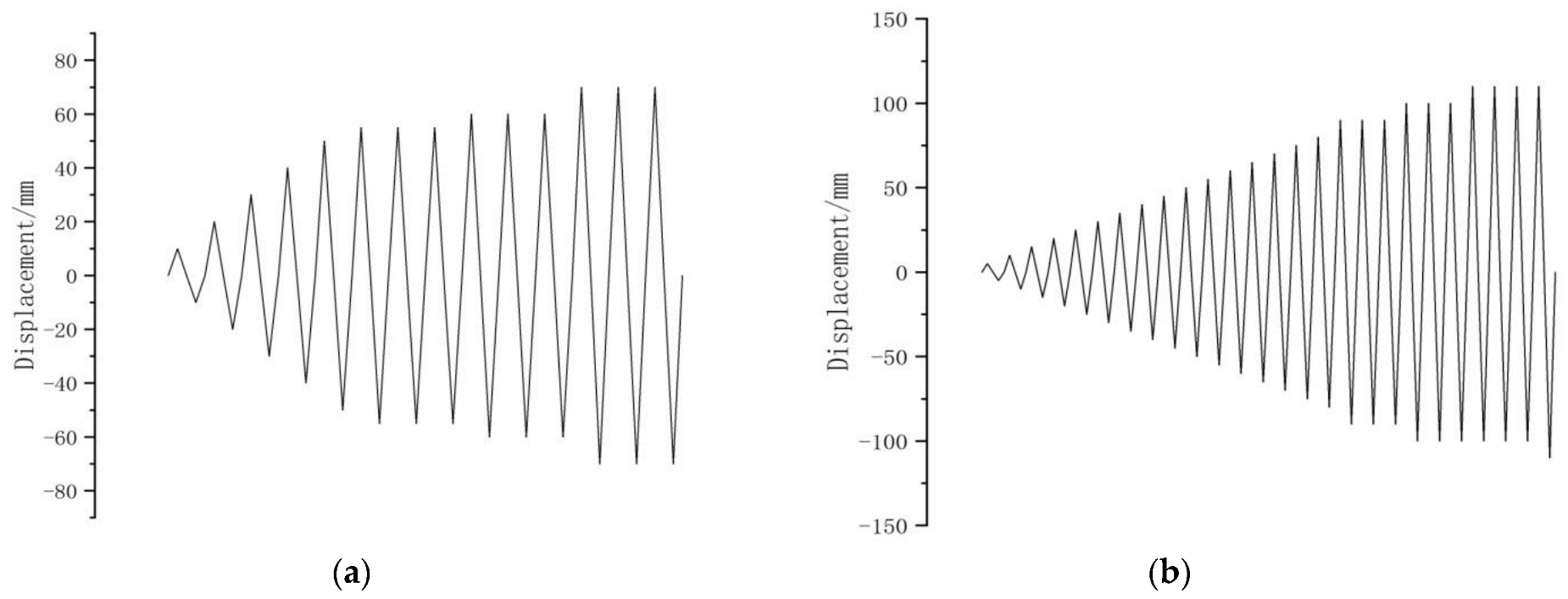
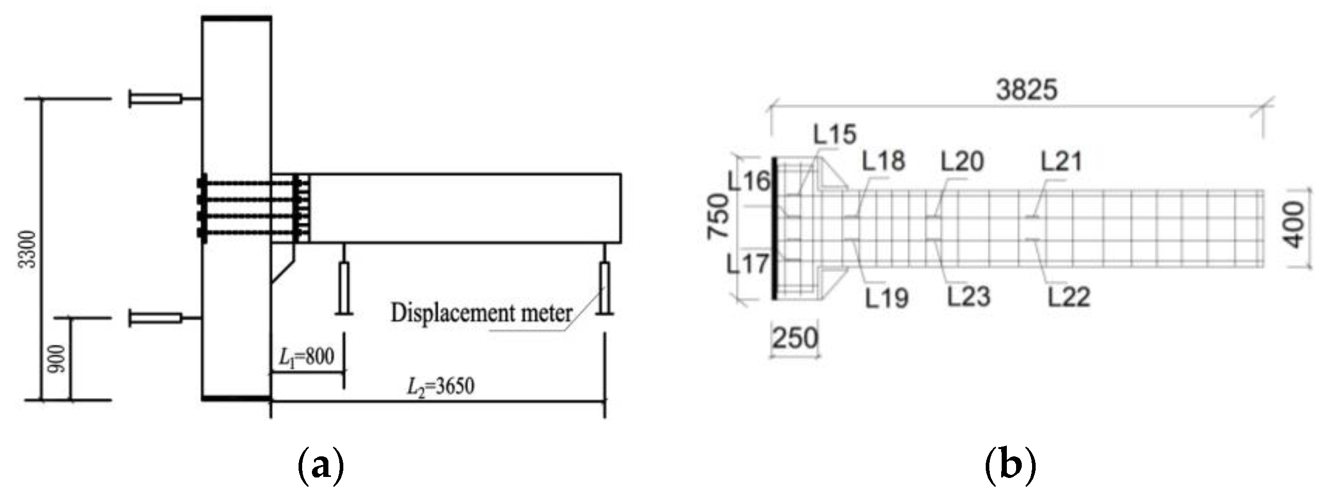
The lateral actuator is attached to the end of the prefabricated beam using a splint in the current pseudo-static test. The pseudostatic test uses a displacement-controlled loading scheme and applies a lateral load with an axial compression ratio of 0.05 to the top of the column. A low-cycle reversed load is applied to the free end of the beam end through the loading system, and lateral loading is accomplished using an electro-hydraulic servo loading system. The stroke of the actuator’s displacement is ±150 mm. Figure 3 depicts the specific loading device on specimens. The entire test-loading procedure is carried out in two stages, the first of which involves loading the displacement for one cycle at each load grade until the specimen yields. The second stage involves loading the displacement for three cycles at each load grade, and the loading is stopped when the specimen strength falls to 85% of its peak load or when the bolts bend. The amount of applied axial pressure should be considered during the loading process, and using the oil pressure gauge, the proper pressure compensation should be carried out. Figure 4 shows the loading plan for constant axial pressure throughout the entire loading procedure.

2.3. Arrangement and Selection of Test Points

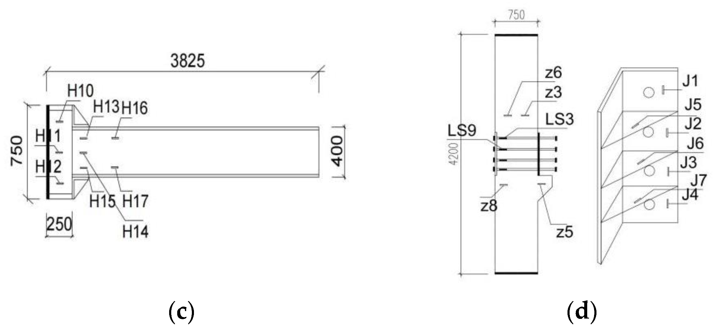
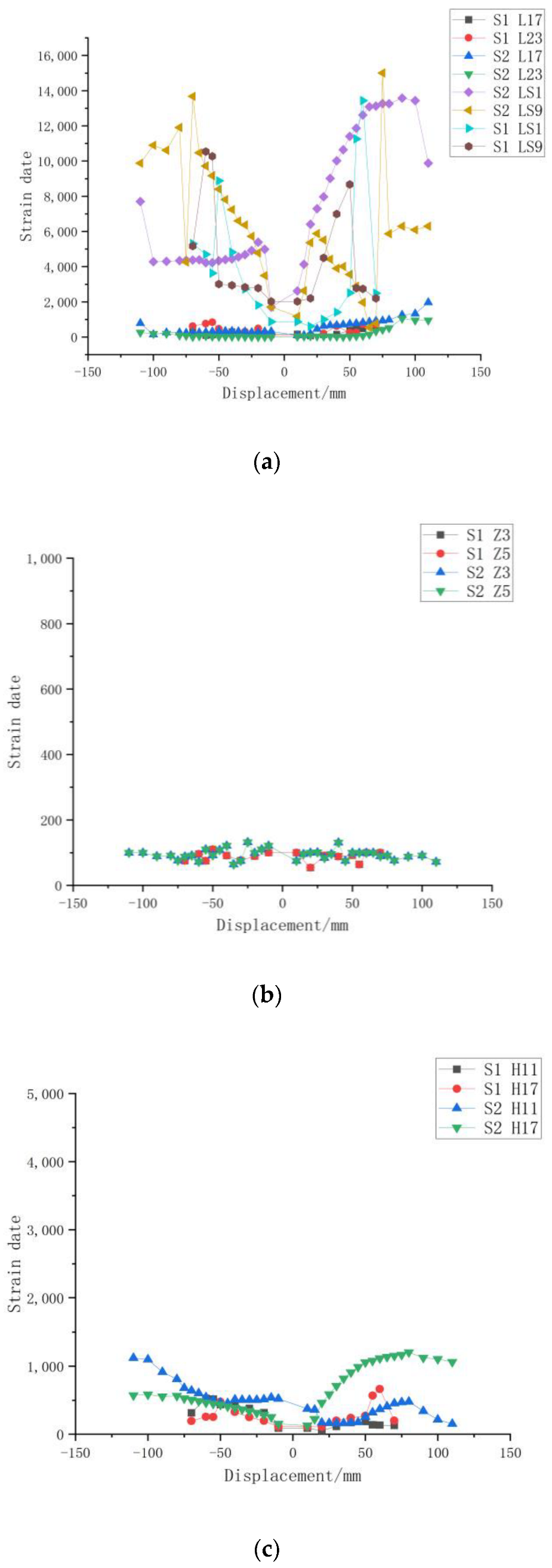
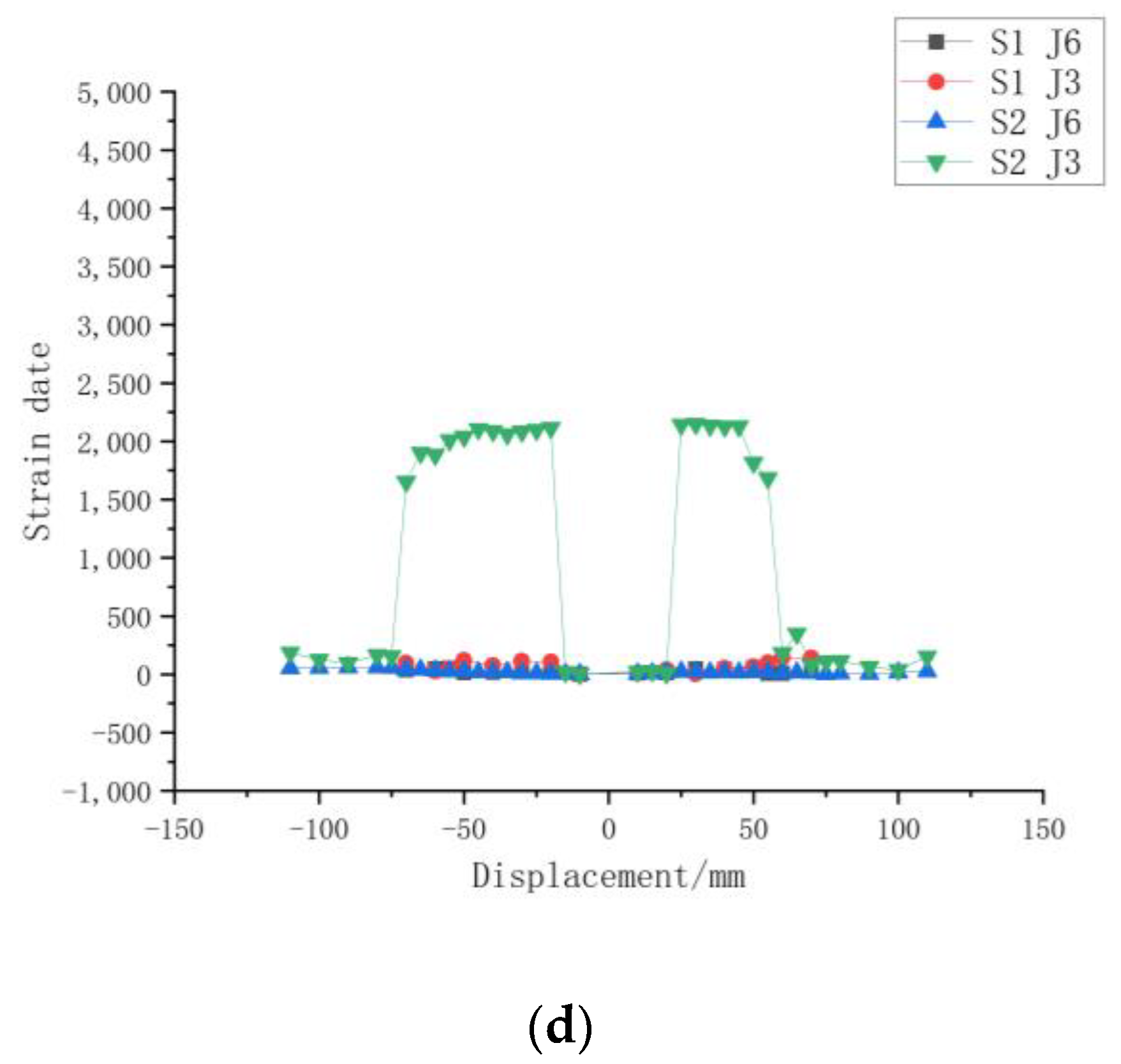
To record displacement values, four displacement sensors are installed at the bottom of the prefabricated beam and the side of the prefabricated column. Rebar strain gauges are installed in strategic locations such as the bracket, steel hunched plate, bolt, junction area, beam end, and column and column bottom ends. Figure 5 shows a portion of these strain gauges, where LS stands for bolt strain, Z for column and beam rebar strain, L for beam rebar strain, H for concrete strain, and J for steel-made haunched plate strain.

3. Results and Discussion

The load displacement pull up was defined as negative (−) and the push down as positive (+). The test involved lifting the prefabricated beam to the horizontal position, calibrating it with a laser level, tightening the bolts with a torque wrench, and setting the current position as the actuator displacement zero point. The prefabricated concrete column displayed no cracks throughout the entire test process.

3.1. Experimental Phenomenon

3.1.1. Specimen S1

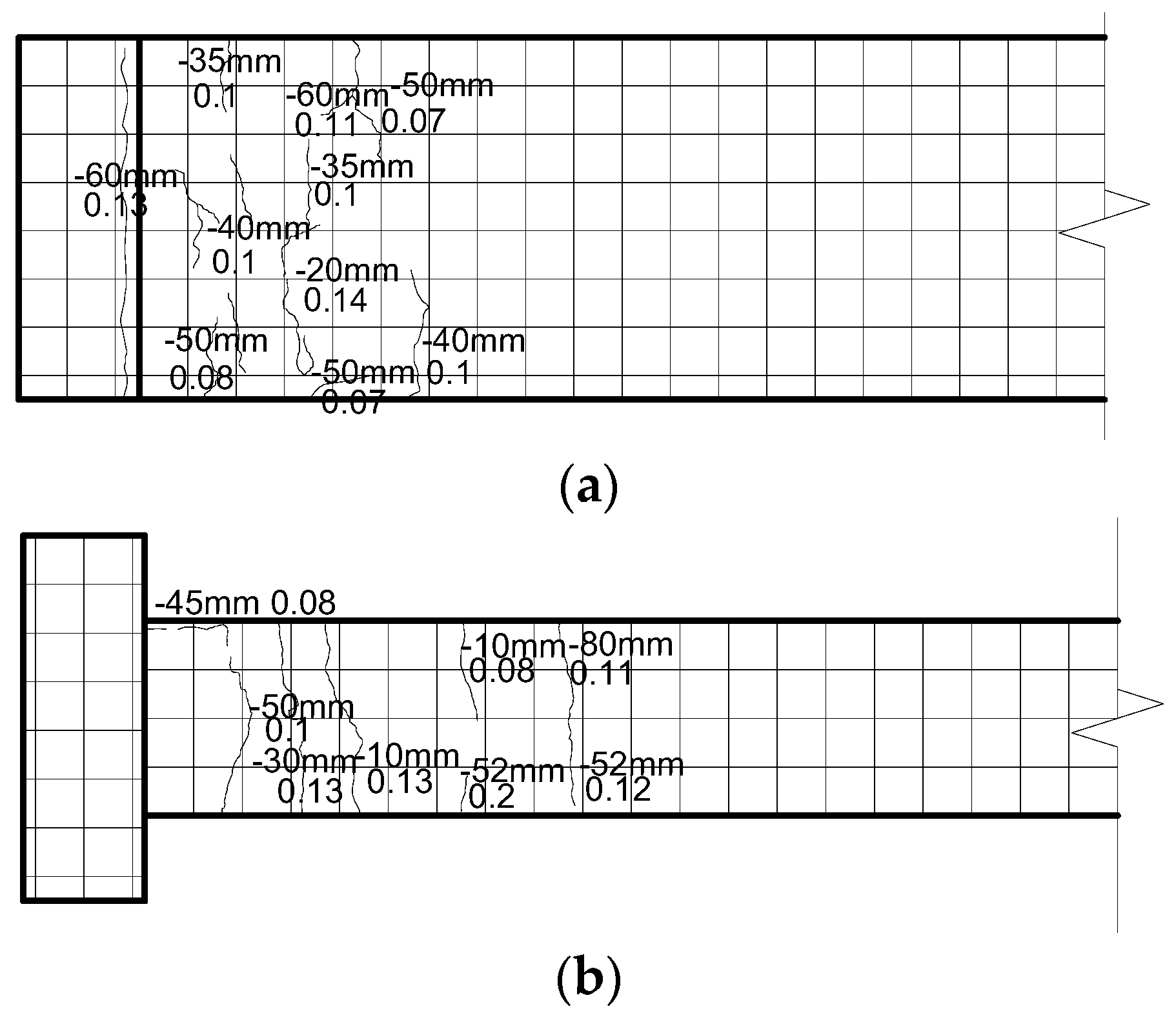
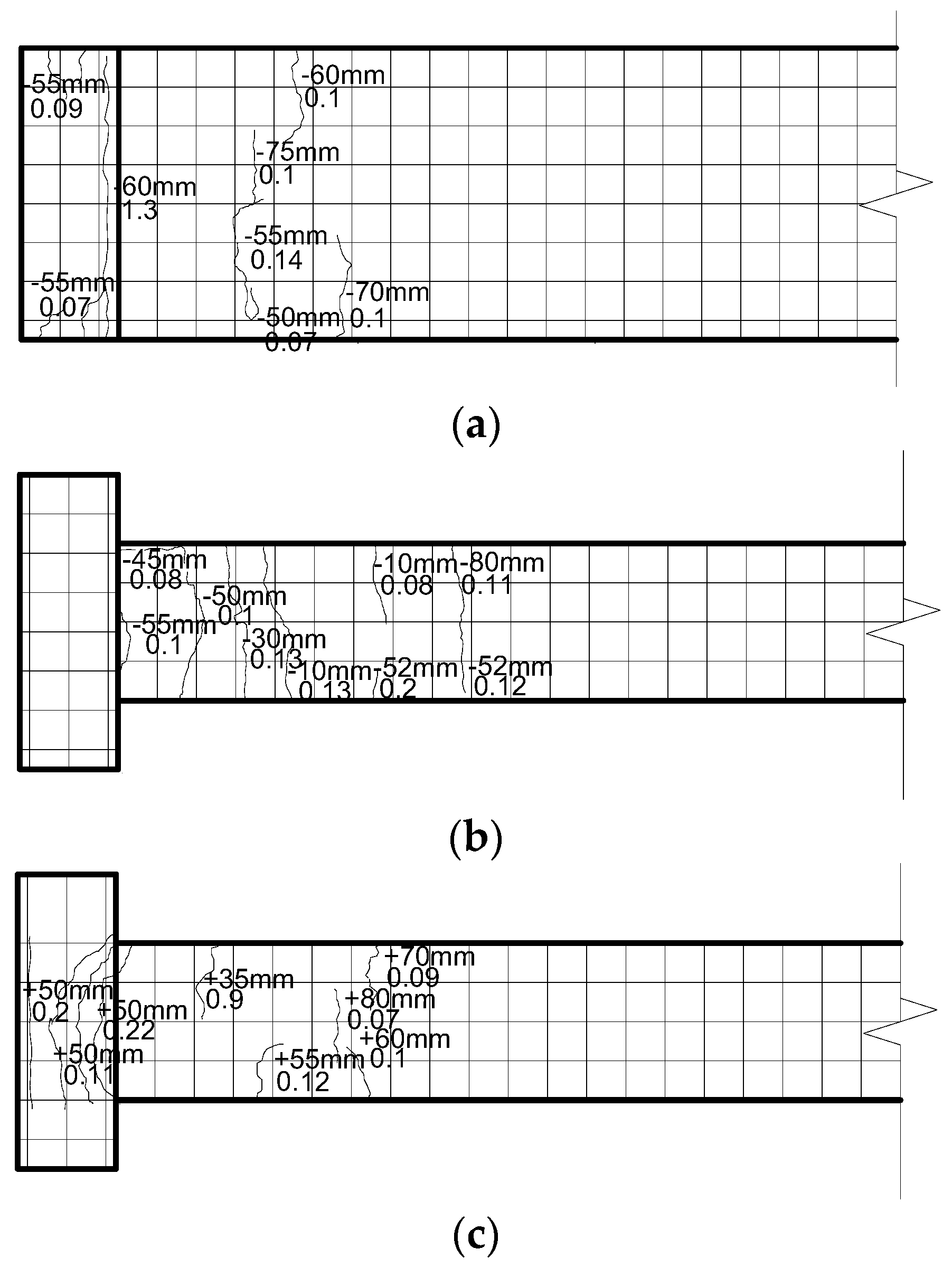
The Specimen S1 uses a 24 mm-diameter Q235 low-strength bolt. When loaded to −10 mm, the lower beam surface (65 cm from the T-shape end) experiences the first crack, which has a width of 0.08 mm, and the grouting layer surface experiences cracks with a width of 0.09 mm. On the left and right beam surfaces when loaded to −40 mm, lateral cracks appear and grow longer as the loading increases. Minor annular cracks appear in the T-shaped end area of the upper beam surface when loaded to +50 mm; these cracks spread outward to the area of greatest stress, and 2 mm-wide cracks appear in the grouting layer. The actuator now shows that there is no longer an increase in the bearing capacity at the beam end. There are no cracks on the column or corbel during the testing process; only the beam develops cracks. Figure 6 depicts the morphology of beam cracks.

3.1.2. Specimen S2

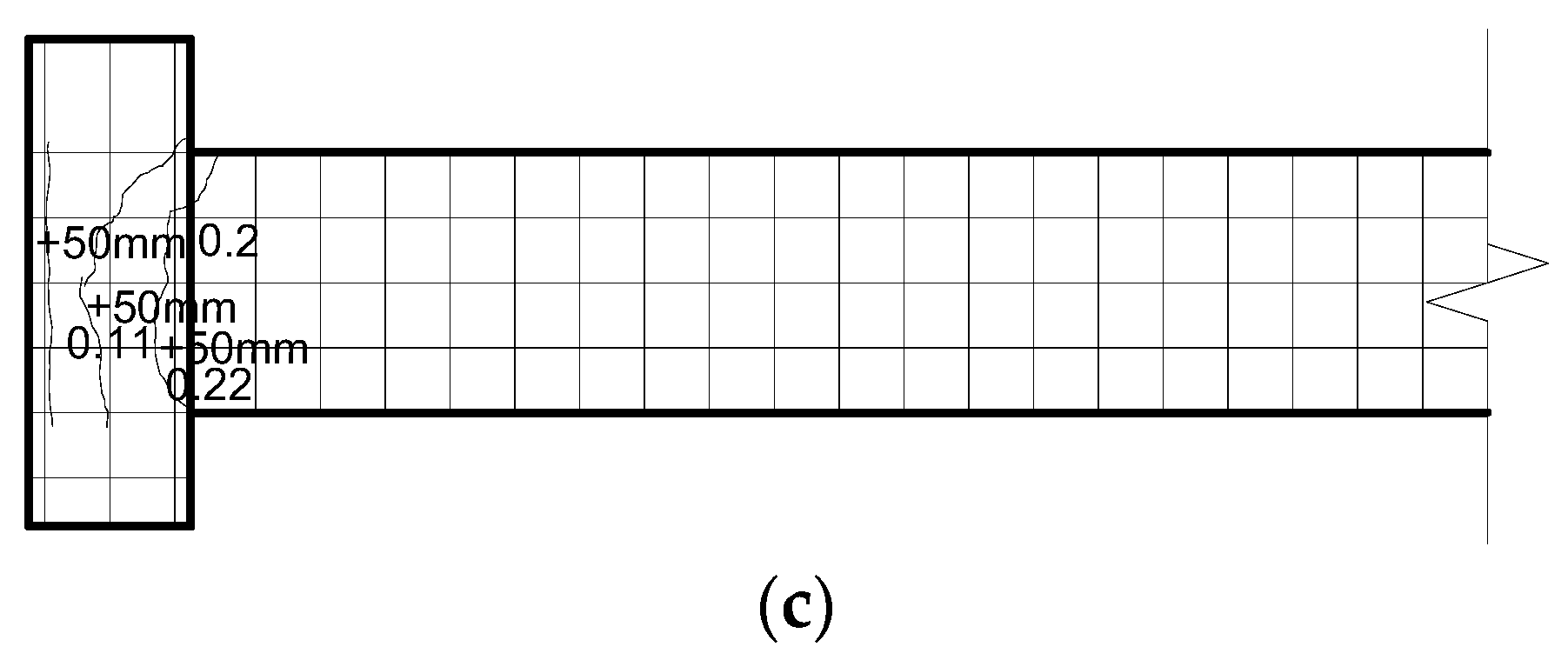
The Q345 ordinary strength bolt with a 24-mm diameter is used in the Specimen S2. When loaded to −40 mm, the lower beam surface (165 cm from the T-shape end) experiences the first crack, which has a width of 0.09 mm. When loaded to −75 mm, the steel-made hunched plate’s interface with the concrete develops 0.1 mm-wide cracks. Multiple cracks develop on the T-shaped end surface with increased loading, and 2 mm-wide cracks develop in the grouting layer. Delamination occurs at the bottom of the grouting layer when the rebar is loaded to −80 mm, and the rebar strain at the T-shaped end exhibits mutation, indicating that the longitudinally stressed rebar has started to bear load. Cycled loading is now used as the loading strategy. When the cycled load is increased to −100 mm, cracks 0.12 mm wide appear at the concrete/steel-made hunched plate interface, and some surface peeling also takes place. On the beam’s surfaces and T-shaped end, cracks continue to form as the load increases, and their width gradually widens. The bolts on the upper part of the joint show obvious bending when recycled and loaded to −110 mm. There are no cracks on the column or corbel during the testing process; only the beam develops cracks. In Figure 7, the crack morphology of beams is depicted.

3.2. Failure Characteristics and Morphologies of Specimens

The following is known based on the low-cycle reserved loading test of the two specimen groups:
  • Failure characteristics and morphology of Specimen S1
    • Under the displacement effect, small-diameter initial cracks first show up at the bottom of prefabricated beams.
    • The specimens eventually fail at the junctions due to the bending of the bolts as a result of the minor annular cracks that develop with increased loading at the stress concentration area of the T-shaped end area.
    • No obvious failure appears to occur at the T-shaped end area during the loading process, which suggests that the bolts at the junction have low strength and cause a decline in the specimen’s overall stress performance.
  • Failure characteristics and morphologies of Specimen S2
    • Under the displacement effect, the upper beam surface—rather than the T-shaped end area of the joint—seems to be the location where the first cracks appear. The cracks lengthen and widen as the load increases, and more cracks also form and spread from the beam end to the beam tail. Concrete peels off in the grouting layer, the steel-made hunched plate and prefabricated beam interface develops cracks, and the specimen ultimately fails at the joint as a result of the bending of the bolts.
    • From the crack initiation, propagation trend and final failure morphology of the prefabricated beam, it can be inferred that the failure mode of the prefabricated beam is ductile failure.
    • In the whole test, no apparent cracks appear on the column or corbel, and the concrete at the T-shaped end area is not crushed, indicating that the introduction of a steel-made haunched plate greatly enhances the compressive capacity of joints. Specimen failure: there is clear bending deformation at the joint bolts, and there is apparent relative rotation between the beam and column, indicating that both bear the moment effect, which exhibits semi-rigid characteristics. These findings demonstrate the strong bearing capacity of this novel type of joint.

3.3. Hysteretic Curve Characteristics of Specimen

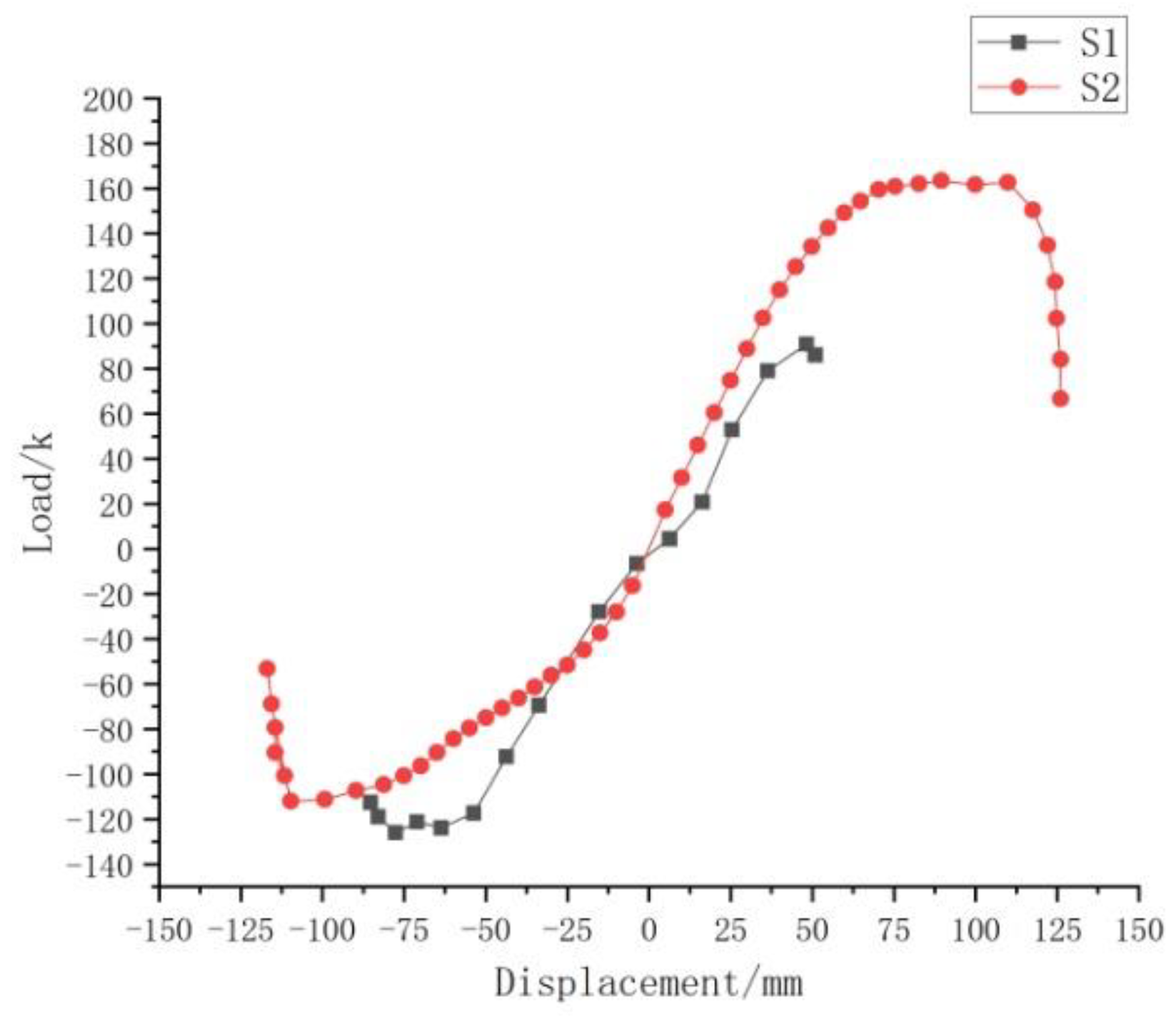
Figure 8 shows the load-displacement hysteretic curves for the two specimen groups, where the load is the lateral load at the end of the beam.
The two hysteretic curve groups can be analyzed to reveal that: at the beginning of the displacement loading, a clear pointed fusiform appears in both curve groups. The hysteretic curve’s slope gradually rises with the increasing load, and the hysteresis loop area expands as well, indicating a good initial capacity for energy consumption. When the cycled loading period begins, the stiffness decreases and the curve clearly exhibits an anti-S shape, indicating that the capacity for energy consumption gradually declines. Because of the weak bolt used in Specimen S1, the reduction in bearing capacity during the entire loading process is negligible, and the pinch phenomenon of the hysteresis curve is not readily apparent, indicating a poor capacity for energy consumption. The slope of Specimen S2’s hysteretic curve is larger and steeper, indicating good deformation recovery and potent plastic deformation. However, the two groups of members’ hysteretic curves as a whole are relatively flat, indicating insufficient energy consumption capacity under low-cycle reserved loading. The ultimate bearing capacity of joint components can be effectively improved by increasing bolt strength, according to a comparison of the two specimen groups, but overall the two specimen groups exhibit poor energy consumption capacity. The two groups of specimens have asymmetric hysteresis curves that are asymmetric in both positive and negative directions. Analysis has demonstrated that the self-weight of the prefabricated beam has an asymmetrical effect on the load during the reserved loading process of the actuator. Additionally, when the actuator is reserved for loading, the prefabricated beam attached to the corbel and bolted to the column has an asymmetrical shear effect on the upper and lower surfaces.

3.4. Skeleton Curve Characteristics of Specimens

The two specimen groups’ load-displacement skeleton curves are plotted in Figure 9, and it is clear that because specimen S1 uses a low-strength bolt, it exhibits no discernible descending stage, indicating poor ductility. Specimen S2’s skeleton curve exhibits a dual-stage characteristic trend. The skeleton curve evolves linearly prior to the turning point, indicating that the specimen is in the elastic working period. After the turning point, the specimen stiffness starts to decline, indicating that it enters an inelastic working period. After the maximum value, the specimen’s bearing capacity sharply declines. The descending stage of the skeleton curve of specimen S2 is more stable and has a higher ductility coefficient than specimen S1. This new type of joint has good deformation capacity and ductility, and the bearing capacity is proportional to the bolt strength. When specimen S2 reaches the limited displacement, the bearing capacity decreases by 59.2%.

3.5. Stiffness Degradation Curves of Specimen

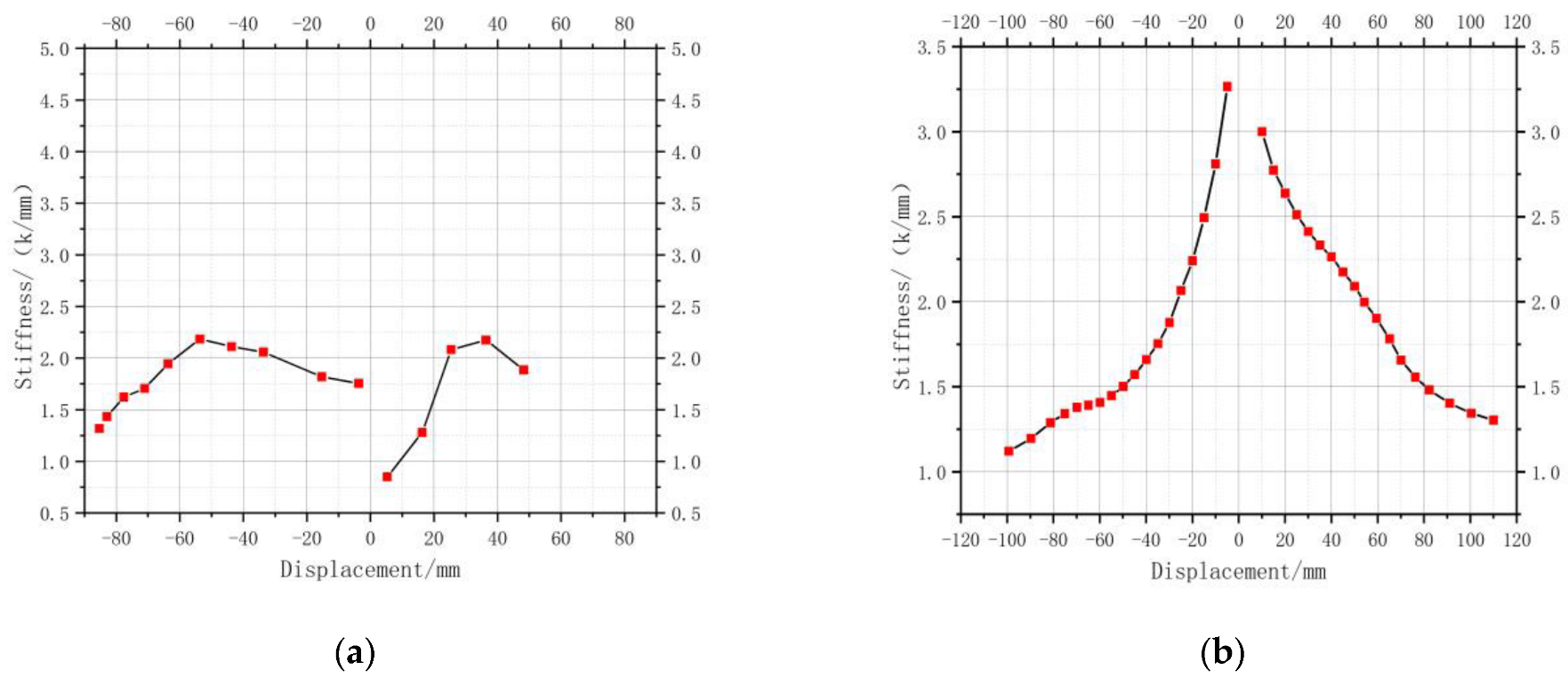
Figure 10 displays the stiffness degradation curves of the two groups of specimens, revealing their striking differences. Specimen S1 has a weak ability to resist lateral movement, while specimen S2 has a strong ability, as can be seen in more detail. Additionally, as the loading displacement increases, specimen S1’s stiffness does not change significantly, whereas specimen S2’s stiffness changes significantly. It degrades quickly at first; as the loading increases, cracks are generated and existing ones continue to grow; the bolts at the joints are deformed, which causes an increase in joint cracks; and as the speed decreases in the later stage, the curve tends to become flat. Since the bolts are primarily responsible for these specimens’ stiffness, specimen S1’s stiffness slightly increases during the initial stage of positive loading, but it gradually decreases as the bolts move into the plastic stage.

3.6. Strain Analysis

Figure 11 shows the strain data for the two specimen groups, where LS stands for bolt strain, Z for column and beam rebar strain, L for beam rebar strain, H for concrete strain, and J for steel-made haunched plate strain. According to an analysis of the strain data from the two specimen groups, the strain evolution law for each component is essentially the same, meaning that the strain on stressed rebar and concrete in prefabricated beams is minimal and does not vary much prior to cracking, and that it increases after cracking. The strain values of the rebar and concrete continuously increase with the increasing load, and the rebar strain at the T-shaped end is greater than the beam tail. Significant concrete cracking can be seen in the middle of the T-shaped end and the middle of the beam, where concrete strain mutation also occurs. The internal longitudinal rebar that has undergone stress does not exhibit any significant mutations, which suggests that plastic deformation has not occurred. The prefabricated column’s overall rebar strain is minimal and shows no discernible change, indicating that the deformation of the prefabricated column under low-cycle reserved loading is minimal. The haunched plate made of bolts and steel has a strain evolution trend that is consistent with the rebar of the prefabricated beam’s T-shaped end.

3.7. Energy Consumption Capacity

The hysteresis area under different displacement loading conditions are abstracted to calculate the energy consumption curve of each hysteresis. This result is plotted in Figure 12. Through comparison, it can be seen that the energy consumption of the two specimen groups during the initial loading phase is essentially the same. The bolt of specimen S2 starts to deform with increasing displacement, which causes the slope of the energy consumption curve to decrease. The energy consumption curve of S2 reaches a turning point and steepens when the displacement reaches 70 mm. Analysis reveals that as the longitudinally stressed rebar inside the prefabricated beam begins to bear load, the specimen’s energy consumption rises and the specimen’s overall energy consumption rises. However, these two specimen groups’ energy consumption coefficients are low, indicating that they have poor energy consumption capacities when subjected to low-cycle reserved loading.

4. Results and Recommendations

It can be deduced from the dry-connection joint test on the prefabricated semi-rigid concrete beam-column that:
  • Based on the observation of the failure mechanisms of two specimen groups, the specimen S1 with low strength bolt exhibits only bending deformation of the bolt and no other joint damage, while all of the specimens exhibit minor cracks on the concrete surface. While in specimen S2 with an ordinary strength bolt, the cracks are concentrated at the T-shaped end and middle of the beam, and the joint damage only consists of the deformation of the bolt, tension cracking of the concrete, and slight compressive peeling of the concrete; the cracks are more widely spaced throughout the specimen. In the subsequent experimental study, enlarging the T-shaped beam end can improve the joint property.
  • This novel type of bolted precast beam−column specimen exhibits excellent rotational properties, large deformation, good overall ductility, and is well suited to resist some load-induced deformation. The bolts bent and deformed as a result of the low circumferential reciprocating load, and the pre-cast beam developed tiny cracks with a maximum crack width of only 0.22 mm. The longitudinal bars of the precast beam did not, however, experience any plastic deformation, and neither did the precast column and corbel. As a result, after an earthquake, the joints can be quickly restored to function by switching out the connecting bolts.
  • Specimen S2’s maximum bearing capacity of 165 k during the loading process and its subsequent decrease to 59.2% when it reached the ultimate displacement show that the new assembled beam-column joint has a high bearing capacity and a strong plastic deformation capacity. It demonstrates the high bearing capacity and strong plastic deformation capacity of the new type of assembled beam column joint. The hysteresis loop curve displays an inverse S-shape under the low circumferential reciprocal load, indicating that the energy dissipation capacity is low. Researchers are urged to incorporate damping energy dissipation devices to increase the joint’s capacity for energy dissipation, control the node’s overall deformation, and effectively protect the node from earthquake-related damage.
  • Only the test phenomena and specimen conclusions were described in this work. To further analyze the seismic mechanical properties of the suggested connection type of joint, finite element simulation should be compared in various working conditions and from various angles.

Author Contributions

Conceptualization, Y.Z. and W.M.; Investigation, K.L.; Resources, W.M. and X.L.; Data curation, Y.Z.; Writing—original draft, Y.Z.; Writing—review & editing, Y.Z., W.M. and K.L.; Visualization, Y.Z.; Supervision, W.M.; Project administration, Y.Z., W.M. and K.L.; Funding acquisition, Y.Z., W.M. and X.L. All authors have read and agreed to the published version of the manuscript.

Funding

Anhui Provincial Provincial Natural Science Research Project-Graduate Project: YJS20210497; Research on the mechanical properties of prefabricated concrete structure nodes based on dry connection, provincial natural science key research project in Anhui Province: KJ2020A0454.

Institutional Review Board Statement

Not applicable.

Informed Consent Statement

Not applicable.

Data Availability Statement

Not applicable.

Conflicts of Interest

The authors declare no conflict of interest.

References

  1. Divyah, N.; Prakash, R.; Srividhya, S.; Sivakumar, A. Parametric study on lightweight concrete-encased short columns under axial compression-Comparison of design codes. Struct. Eng. Mech. 2022, 83, 387–400. [Google Scholar] [CrossRef]
  2. Prakash, R.; Thenmozhi, R.; Raman, S.N.; Subramanian, C. Characterization of eco-friendly steel fiber-reinforced concrete containing waste coconut shell as coarse aggregates and fly ash as partial cement replacement. Struct. Concr. 2019, 21, 437–447. [Google Scholar] [CrossRef]
  3. Prakash, R.; Thenmozhi, R.; Raman, S.N. Mechanical characterisation and flexural performance of eco-friendly concrete produced with fly ash as cement replacement and coconut shell coarse aggregate. Int. J. Environ. Sustain. Dev. 2019, 18, 131–148. [Google Scholar] [CrossRef]
  4. Prakash, R.; Thenmozhi, R.; Raman, S.N.; Subramanian, C. Fibre reinforced concrete containing waste coconut shell aggregate, fly ash and polypropylene fibre. Rev. Fac. Ing. Univ. Antioq. 2020, 94, 33–42. [Google Scholar] [CrossRef] [Green Version]
  5. Iverson, J.K.; Hawkins, N.M. Performance of Precast Concrete Building Structures During Northridge Earthquake. PCI J. 1994, 39, 38–55. [Google Scholar] [CrossRef]
  6. Priestley, M.J.N.; Macrae, G.A. Seismic tests of precast beam-to-column joint subassemblages with unbounded tendons. PCI J. 1996, 41, 64–81. [Google Scholar] [CrossRef] [Green Version]
  7. Al-Masni, M.A. Final Report “Earthquake Building Risk Assessment in Sana’a City, Yemen”; FY2012A; Asian Disaster Reduction Center, 2012; Available online: https://www.adrc.asia/aboutus/vrdata/finalreport/2012A_YEM_fr.pdf (accessed on 12 April 2022).
  8. Miranda, E.; Mosqueda, G.; Retamales, R.; Pekcan, G. Performance of Nonstructural Components during the 27 February 2010 Chile Earthquake. Earthq. Spectra 2012, 28, 453–471. [Google Scholar] [CrossRef]
  9. Torra-Bilal, I.; Mahamid, M.; Baran, E. Cyclic behaviour of precast beam-to-column connections: An experimental and numerical investigation. Structures 2022, 35, 939–957. [Google Scholar] [CrossRef]
  10. Naserabad, A.Z.; Ghasemi, M.R.; Shabakhty, N.; Ghohani Arab, H. Design of a Novel Prefabricated Bolted I-Beam to Box-Column Connection Using Numerical Analysis Under Cyclic Load. Int. J. Steel Struct. 2019, 19, 1431–1445. [Google Scholar] [CrossRef]
  11. Lee, D.J.; Lee, J.D.; Oh, T.S.; Kang, T.H.K. Seismic Experiment of Precast Concrete Exterior Beam-Column Joint Using Bolt Type Connection and Prestressing Method. J. Korea Concr. Inst. 2014, 26, 125–133. [Google Scholar] [CrossRef]
  12. Oh, S.H.; Kim, Y.J.; Hong, S. Seismicperformance of steel structures with slit dampers. Eng. Struct. 2009, 31, 1997–2008. [Google Scholar] [CrossRef]
  13. Ding, K.W.; Liu, J.H.; Ma, W.; Liu, Y.L. Experimental study on seismic performance of new prefabricated semi-rigid joint. China Civ. Eng. J. 2021, 54, 1–7. [Google Scholar]
  14. Ertas, O.; Ozden, S.; Ozturan, T. Ductile connections in precast concrete moment resisting frames. PCI J. 2006, 51, 66–76. [Google Scholar] [CrossRef]
  15. Wang, P.; Wang, Z.; Pan, J.; Song, L. Experimental investigation on behavior of stiffened top and seat angle beam-to-column connections in steel frame. J. Build. Struct. 2017, 38, 21–28. (In Chinese) [Google Scholar] [CrossRef]
  16. Wang, H.S.; Marino, E.M.; Pan, P.; Liu, H.; Nie, X. Experimental study of a novel precast prestressed reinforced concrete beam-to-column joint. Eng. Struct. 2018, 156, 68–81. [Google Scholar] [CrossRef]
  17. Vidjeapriya, R.; Jaya, K.P. Experimental study on two simple mechanical precastbeam-column connections under reverse cyclic loading. J. Perform. Constr. Facil. 2013, 27, 402–414. [Google Scholar] [CrossRef]
  18. Lacerda, M.M.S.; da Silva, T.J.; Alva, G.M.S.; de Lima, M.C.V. Influence of the vertical grouting in the interface between corbel and beam in beam-to-column connections of precast concrete structures—An experimental analysis. Eng. Struct. 2018, 172, 201–213. [Google Scholar] [CrossRef]
  19. Vasconez, R.M.; Naaman, A.E.; Wight, J.K. Behavior of HPFRC Connections for Precast Concrete Frames under Reversed Cyclic Loading. PCI J. 1998, 43, 58–71. [Google Scholar] [CrossRef]
  20. Ngo, T.T.; Pham, T.M.; Hao, H. Ductile and dry exterior joints using CFRP bolts formoment-resisting frames. Structures 2020, 28, 668–684. [Google Scholar] [CrossRef]
  21. Kurama, Y.C.; Sritharan, S.; Fleischman, R.B.; Restrepo, J.I.; Henry, R.S.; Cleland, N.M.; Ghosh, S.K.; Bonelli, P. Seismic-resistant precast concrete structures: State of the art. Eng. Struct. 2018, 144, 03118001. [Google Scholar] [CrossRef] [Green Version]
  22. Ye, M.; Jiang, J.; Chen, H.M.; Zhou, H.; Song, D. Seismic behavior of an innovative hybrid beam-column connection for precast concrete structures. Eng. Struct. 2021, 227, 111436. [Google Scholar] [CrossRef]
  23. Vecchio, C.D.; Ludovico, M.D.; Balsamo, A.; Prota, A. Seismic retrofifit of real beam-column joints using fifiber-reinforced cement composites. Eng. Struct. 2018, 144, 04018026. [Google Scholar] [CrossRef]
  24. Parastesh, H.; Hajirasouliha, I.; Ramezani, R. A New ductile moment-resisting connection for precast concrete frames in seismic regions: An experimental investigation. Eng. Struct. 2014, 70, 144–157. [Google Scholar] [CrossRef]
  25. Yuksel, E.; Karadogan, H.F.; Bal, İ.E.; Ilki, A.; Bal, A.; Inci, P. Seismic behavior of two exterior beam–column connections made of normal-strength concrete developed for precast construction. Eng. Struct. 2015, 99, 157–172. [Google Scholar] [CrossRef]
  26. Lacerda, M.M.S. Analysis of the Inflfluence of Grouting and Reinforcing Bars Position on Beam-column Connection in Precast Concrete Structures. Master′s Dissertation, Faculty of Civil Engineering, Federal University of Uberlândia, Uberlândia, Brazil, 2018. [Google Scholar]
  27. Yang, D.; Jia, B.; Guo, R. Research on seismic behavior of GFRP-reinforced concrete interior beam-column joints. J. Build. Struct. 2021, 43, 225–236. [Google Scholar] [CrossRef]
  28. Zhang, J.; Li, C.; Rong, X.; Zhang, B. Experimental study on the mechanical performance of prefabricated concrete beam-column joints with different connection forms. J. Civ. Environ. Eng. 2021. [Google Scholar] [CrossRef]
  29. Li, Z.; Huang, Y.; Lu, W.; He, H. Seismic behavior of semi-rigid joints of precast concrete beam and column. J. Civ. Environ. Eng. 2021. [Google Scholar] [CrossRef]
  30. Li, H.; Du, Y.; Li, F. Experimental study and influential parameters analysis on seismic behavior of prefabricated concrete beam-column joints. J. Build. Struct. 2021, 42. [Google Scholar] [CrossRef]
  31. Li, Y.; Huang, B. Evaluation on Seismic Performance of Beam-Column Joints of Fabricated Steel Structure with Replaceable Energy-Dissipating Elements. Sustainability 2022, 14, 3350. [Google Scholar] [CrossRef]
  32. Yang, H.; Yang, B.; Wang, H.; Zhang, M.; Ni, S. Research on Dynamic Characteristics of Joint of RC Frame Structure with NES. Sustainability 2022, 14, 11229. [Google Scholar] [CrossRef]
  33. Wang, H.; Wu, Y.; Wei, M.; Wang, L.; Cheng, B. Hysteretic behavior of geopolymer concrete with active confinement subjected to monotonic and cyclic axial compression: An experimental study. Materials 2020, 13, 3997. [Google Scholar] [CrossRef] [PubMed]
  34. Wang, H.; Wu, Y.; Qin, X.; Li, L.; Chen, H.; Cheng, B. Behavior of cement concrete confined by fabric-reinforced geopolymer mortar under monotonic and cyclic compression. Structures 2021, 34, 4731–4744. [Google Scholar] [CrossRef]
  35. Abdelwahed, B.S.; Kaloop, M.R.; El-Demerdash, W.E. Nonlinear numerical assessment of exterior Beam-Column connections with Low-Strength concrete. Buildings 2021, 11, 562. [Google Scholar] [CrossRef]
  36. Cheng, B.; Huang, J.; Lu, K.; Li, J.; Gao, G.; Wang, T.; Chen, H. BIM-enabled life cycle assessment of concrete formwork waste reduction through prefabrication. Sustain. Energy Technol. Assess. 2022, 53, 102449. [Google Scholar] [CrossRef]
  37. GB 50010-2010; Code for Design of Concrete Structures. China Construction Industry Press: Beijing, China, 2015.
  38. JGJ/T 101-2015; Specificating of Testing Methods for Earthquake Resistant Building. China Construction Industry Press: Beijing, China, 2015.
  39. GB/T50152-2012; Standard for Test Method of Concrete Structures. China Construction Industry Press: Beijing, China, 2012.
  40. GB/T228.1-2010; Metallic Materials-Tensile Testing-Part 1: Method of Test at Room Temperature. China Standards Press: Beijing, China, 2010.
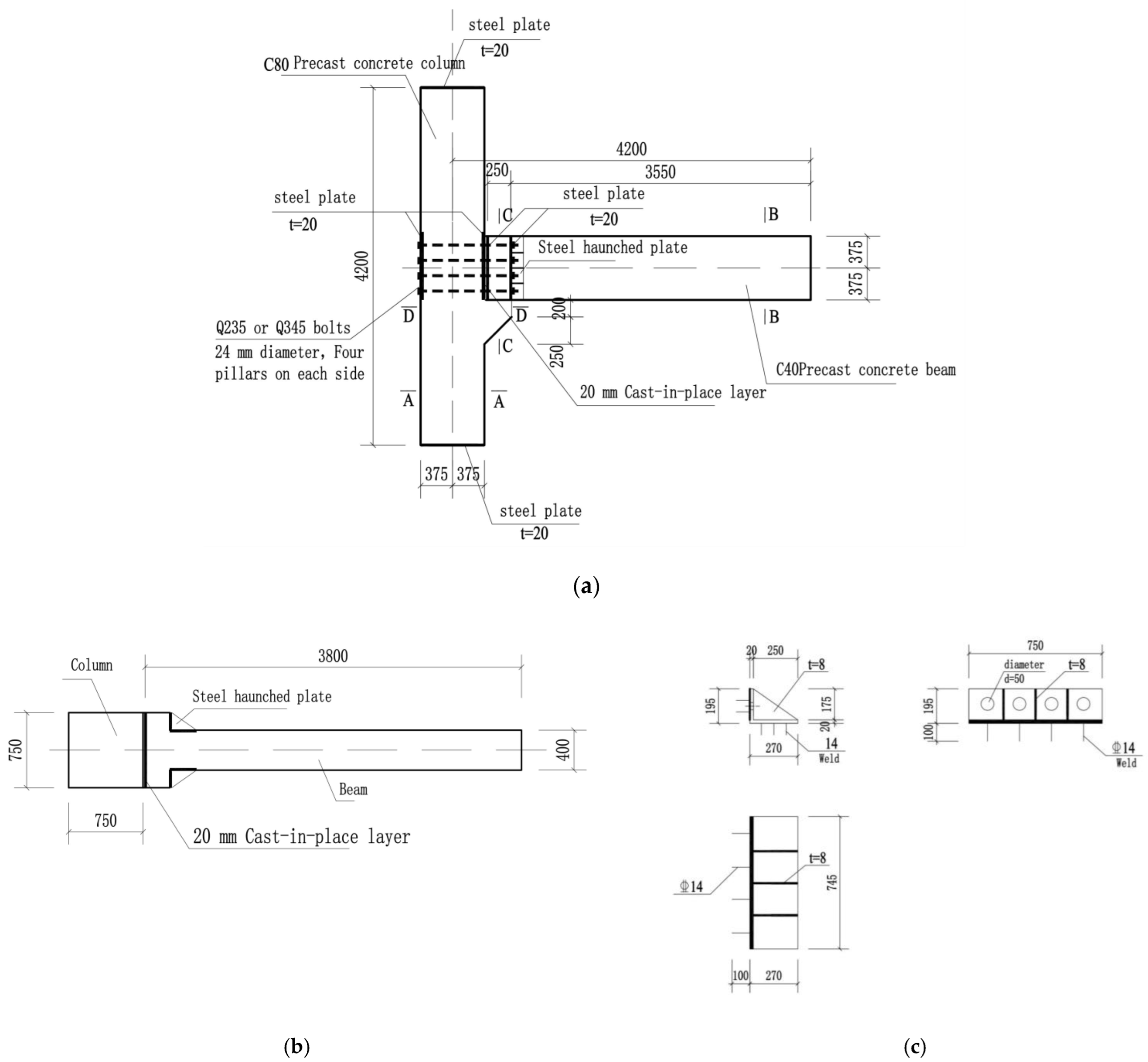
Figure 1. Design drawing of specimen: (a) Overall elevation of specimen; (b) Top view of prefabricated beam; (c) Detailed drawing of steel haunched plate.
Sustainability 14 15644 g001
Figure 2. Rebar arrangement of specimen: (a) Rebar arrangement of T-shaped beam end; (b) Rebar arrangement of B-B beam section; (c) Rebar arrangement of A-A column section; (d) Rebar arrangement of D-D corbel section; (e) Detailed reinforcement arrangement of corbel.
Sustainability 14 15644 g002
Figure 3. Illustration of specimen and loading device: (a) Loading device diagram; (b) Photo of the test site.
Sustainability 14 15644 g003
Figure 4. Displacement loading scheme: (a) Q235a. Loading scheme for Q235 low strength bolt; (b) Q345b. Loading scheme for Q345 ordinary strength bolt.
Sustainability 14 15644 g004
Figure 5. Strain gauges layout: (a) Displacement meter layout; (b) Rebar strain gauges layout on beam; (c) Part concrete strain gauges layout on prefabricated beam surface; (d) Part strain gauges layout on bolt and steel made haunched plate.
Sustainability 14 15644 g005aSustainability 14 15644 g005b
Figure 6. Crack map on specimen S1: (a) Crack map on beam side surface; (b) Crack map at beam bottom surface; (c) Crack map at beam top surface.
Sustainability 14 15644 g006aSustainability 14 15644 g006b
Figure 7. Crack map on specimen S2: (a) Crack map on beam side surface; (b) Crack map at beam bottom surface; (c) Crack map at beam top surface.
Sustainability 14 15644 g007
Figure 8. Load-displacement hysteresis curve: (a) Load-displacement hysteresis curve of specimen S1; (b) Load-displacement hysteresis curve of specimen S2.
Sustainability 14 15644 g008
Figure 9. Skeleton curve.
Sustainability 14 15644 g009
Figure 10. Stiffness degradation curve: (a) Stiffness degradation curve of specimen S1; (b) Stiffness degradation curve of specimen S2.
Sustainability 14 15644 g010
Figure 11. Strain data of rebar, concrete, steel haunched plate and column: (a) Strain data of reinforcement and bolt; (b) Strain data of prefabricated column; (c) Concrete strain data of prefabricated beam; (d) Strain data of steel haunched plate.
Sustainability 14 15644 g011aSustainability 14 15644 g011b
Figure 12. Energy consumption curve.
Sustainability 14 15644 g012
Table 1. Rebar property parameters.
TypeDiameter/mmYield Strength/MPaLimit Strength/MPaElongation
Low strength bolt (Q235)24297.1504.720.9%
Ordinary bolt (Q345)24436.2764.536.6%
HRB40012465.2577.321.6%
HRB40014447.4567.623.2%
HRB40025456.6605.720.2%
Table 2. Concrete property parameters.
Concrete Grade3d (N/mm2)7d (N/mm2)28d (N/mm2)
C4026.1338.1348.15
C8028.2078.2287.12
Publisher’s Note: MDPI stays neutral with regard to jurisdictional claims in published maps and institutional affiliations.