

Model Test and Numerical Simulation Research of Reinforced Soil Retaining Walls under Cyclic Loads


Abstract
:1. Introduction
2. Experimental Study
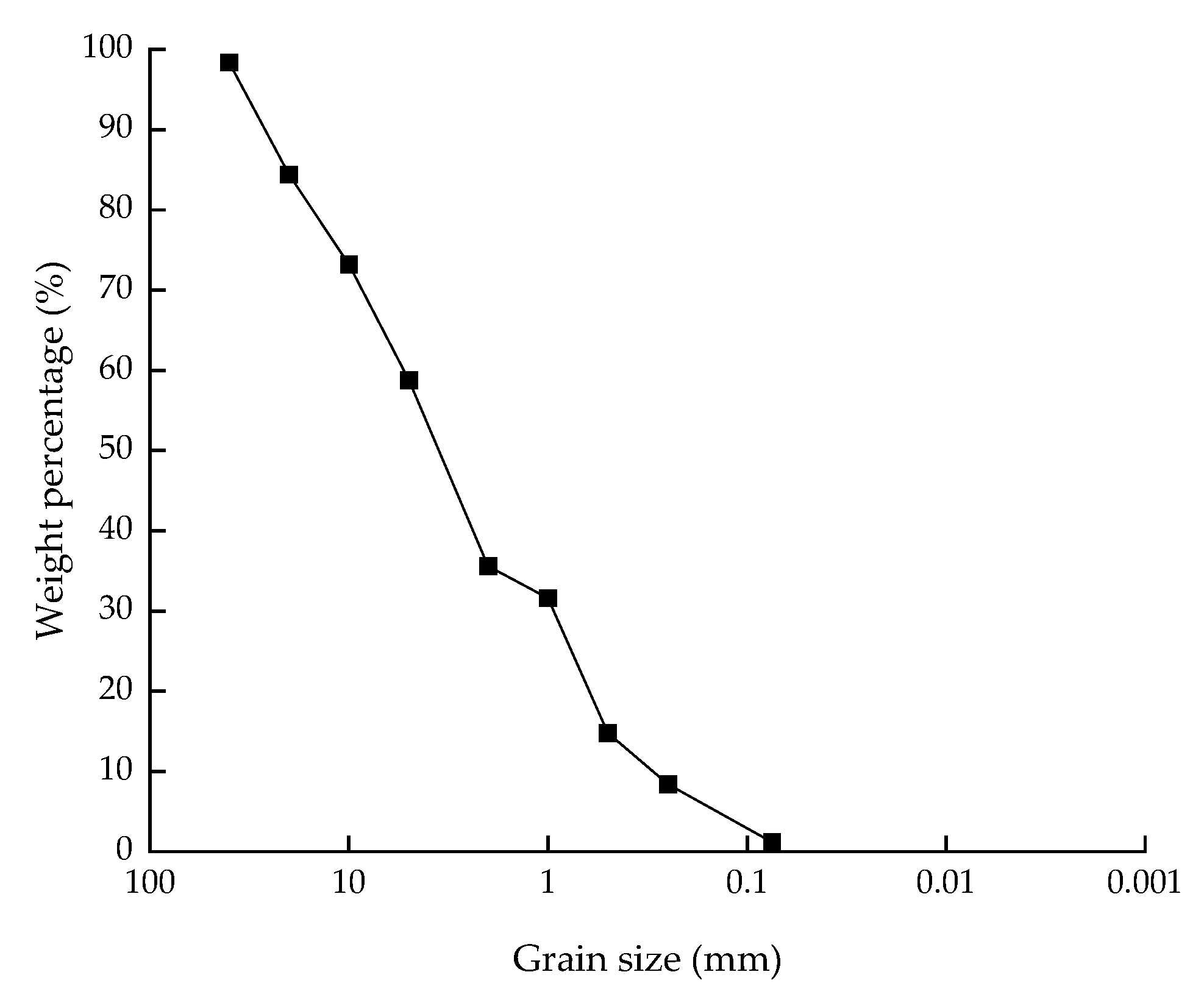
2.1. Wall Filling
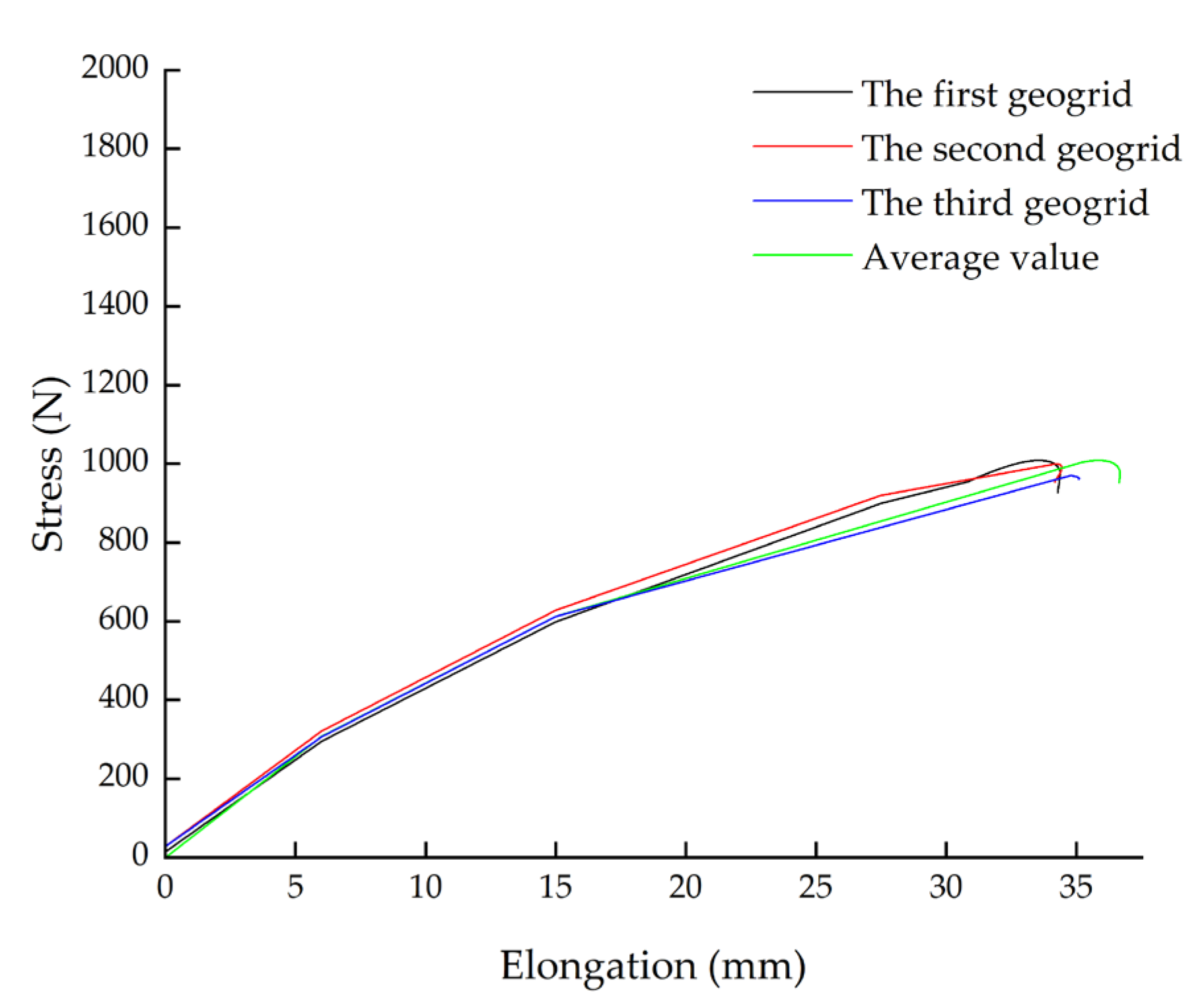
2.2. Reinforcement
2.3. Model Size and Monitoring Instrument Arrangement
2.4. Filling Requirements and Loading Scheme
3. Analysis of Model Test Results
3.1. Analysis of Vertical Dynamic Earth Pressure Due to External Loads
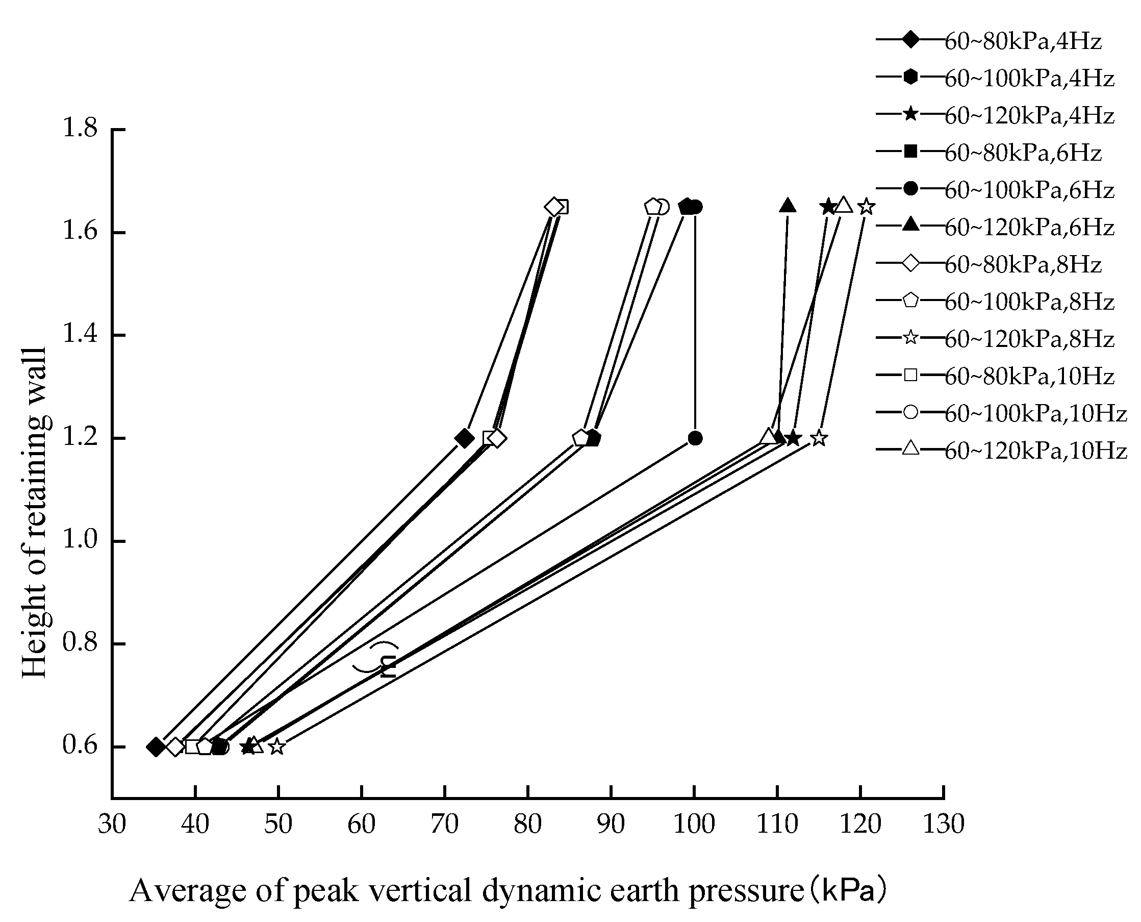
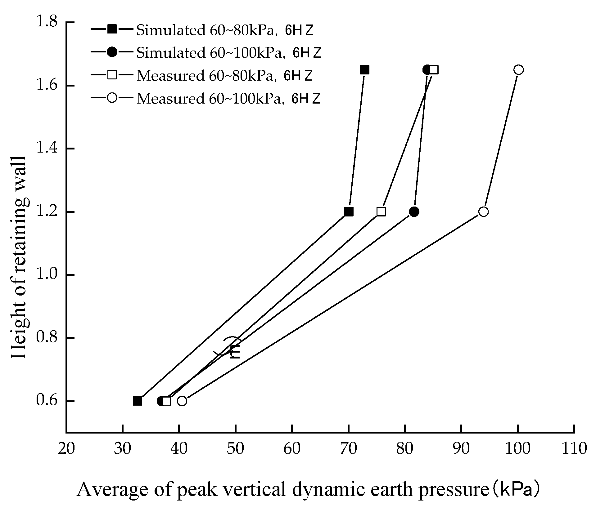
3.1.1. Vertical Dynamic Earth Pressure along the Wall Height
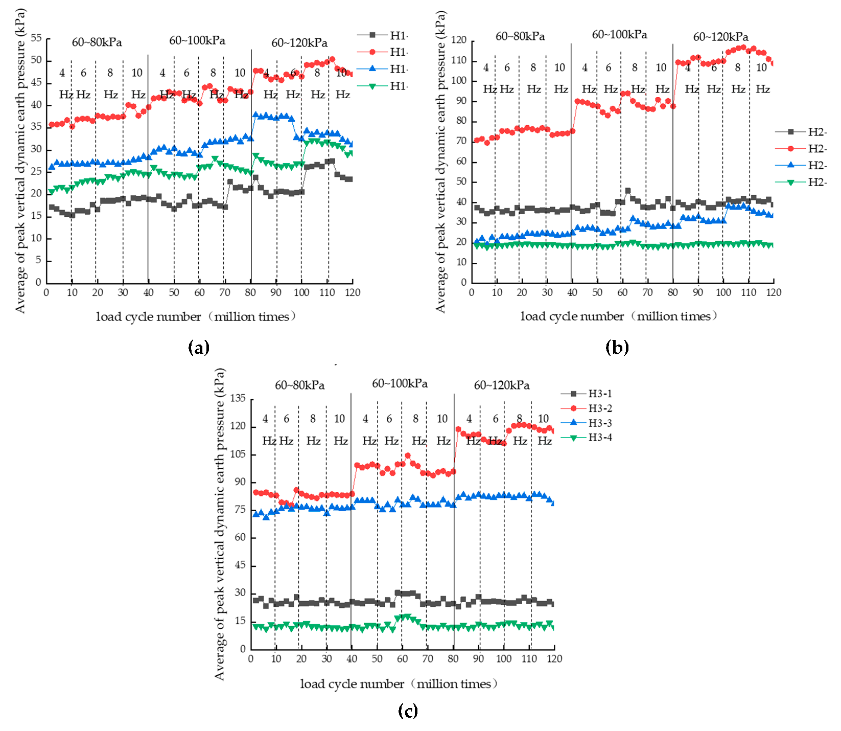
3.1.2. Vertical Dynamic Earth Pressure with the Increase in Load Cycle Number
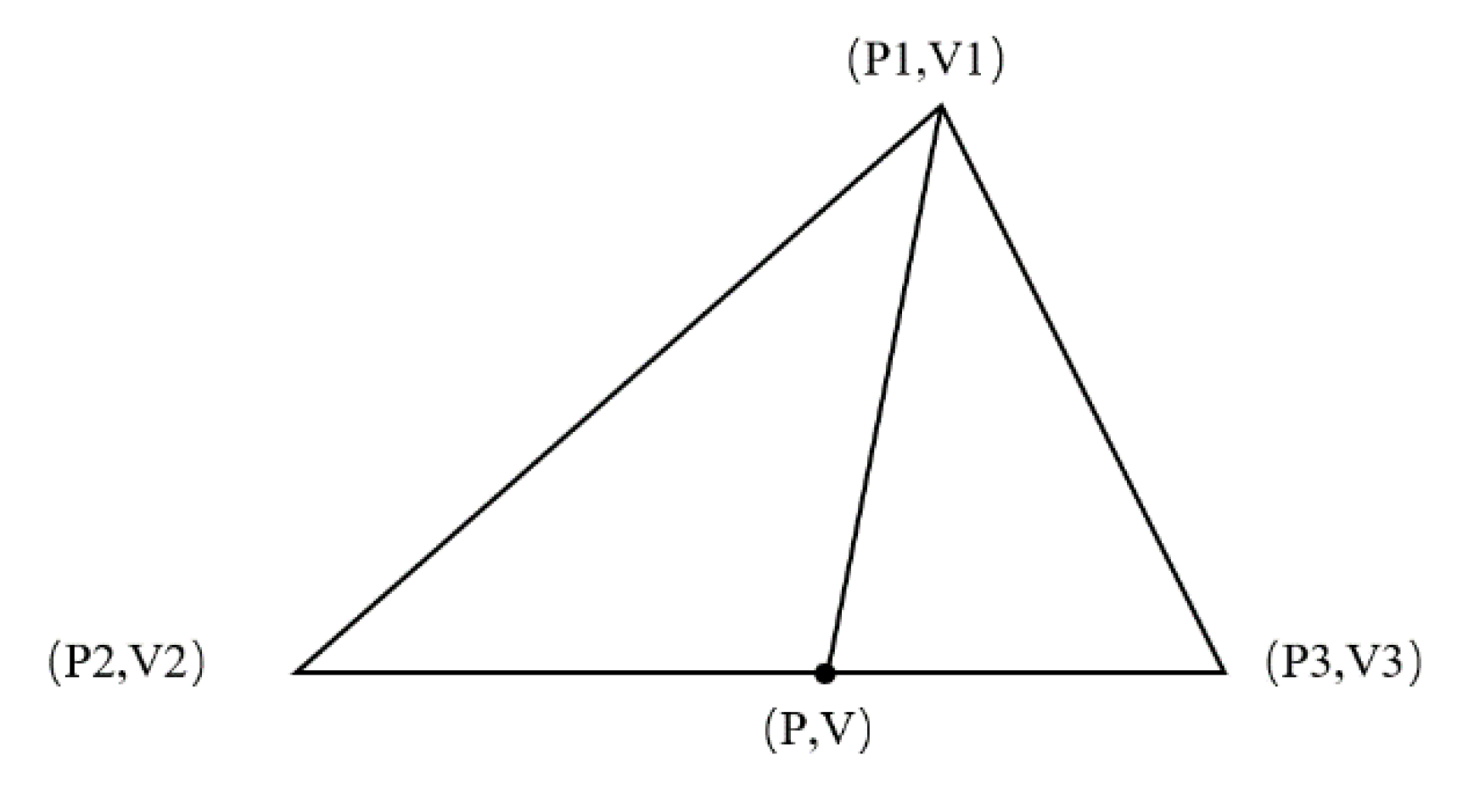
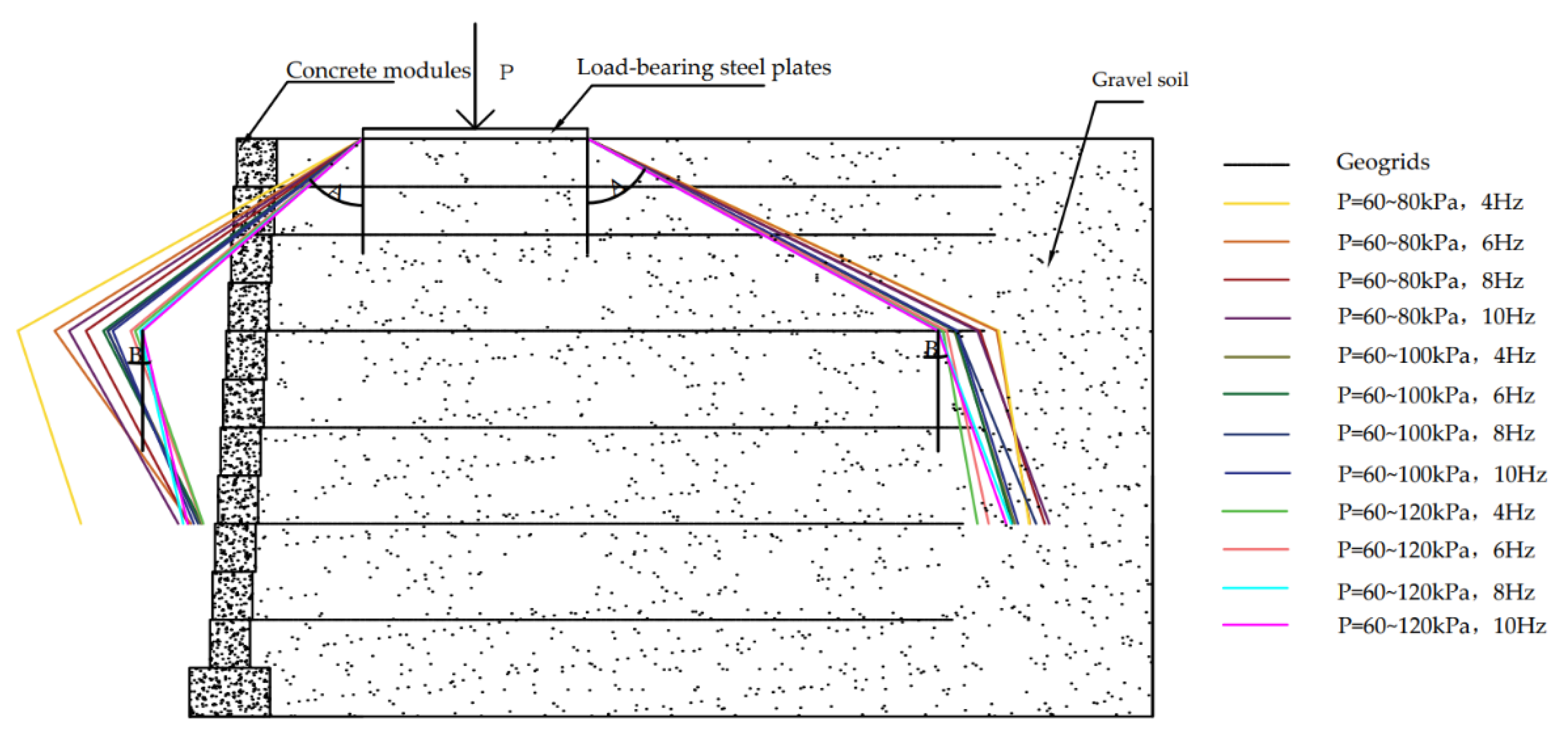
3.2. Analysis of Stress Diffusion Characterization
- There was a maximum stress diffusion angle within the reinforced body; the diffusion angle at the top was slightly larger than the diffusion angle in the middle.
- The stress diffusion angle within the reinforced soil caused by the external load on the side of the retaining wall close to the panel was smaller than that on the side away from the panel.
- The stress diffusion angle A decreased with the increase in dynamic stress amplitude, while diffusion angle B had no obvious pattern.
- The stress diffusion angles A and B had no obvious pattern with the increase in frequency.
- The diffusion angle at the top reaches its maximum value when the loading amplitude was 60–80kPa and the dynamic stress frequency was 4 Hz, while there was no obvious pattern in the middle.
4. Numerical Simulation
4.1. Model Material Parameters
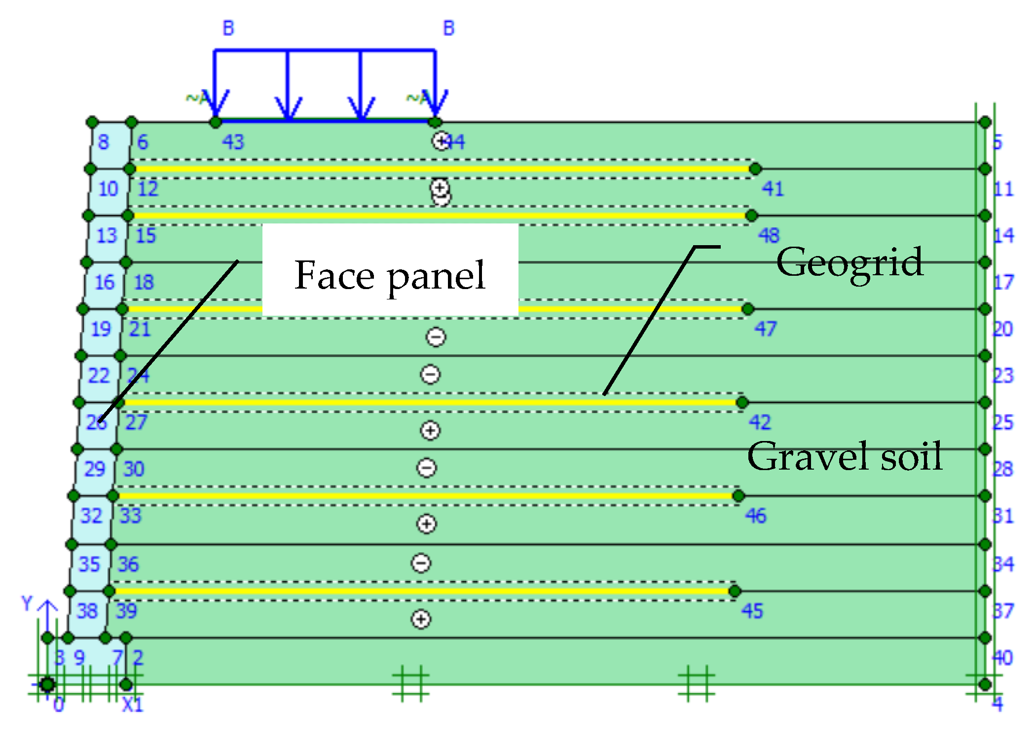
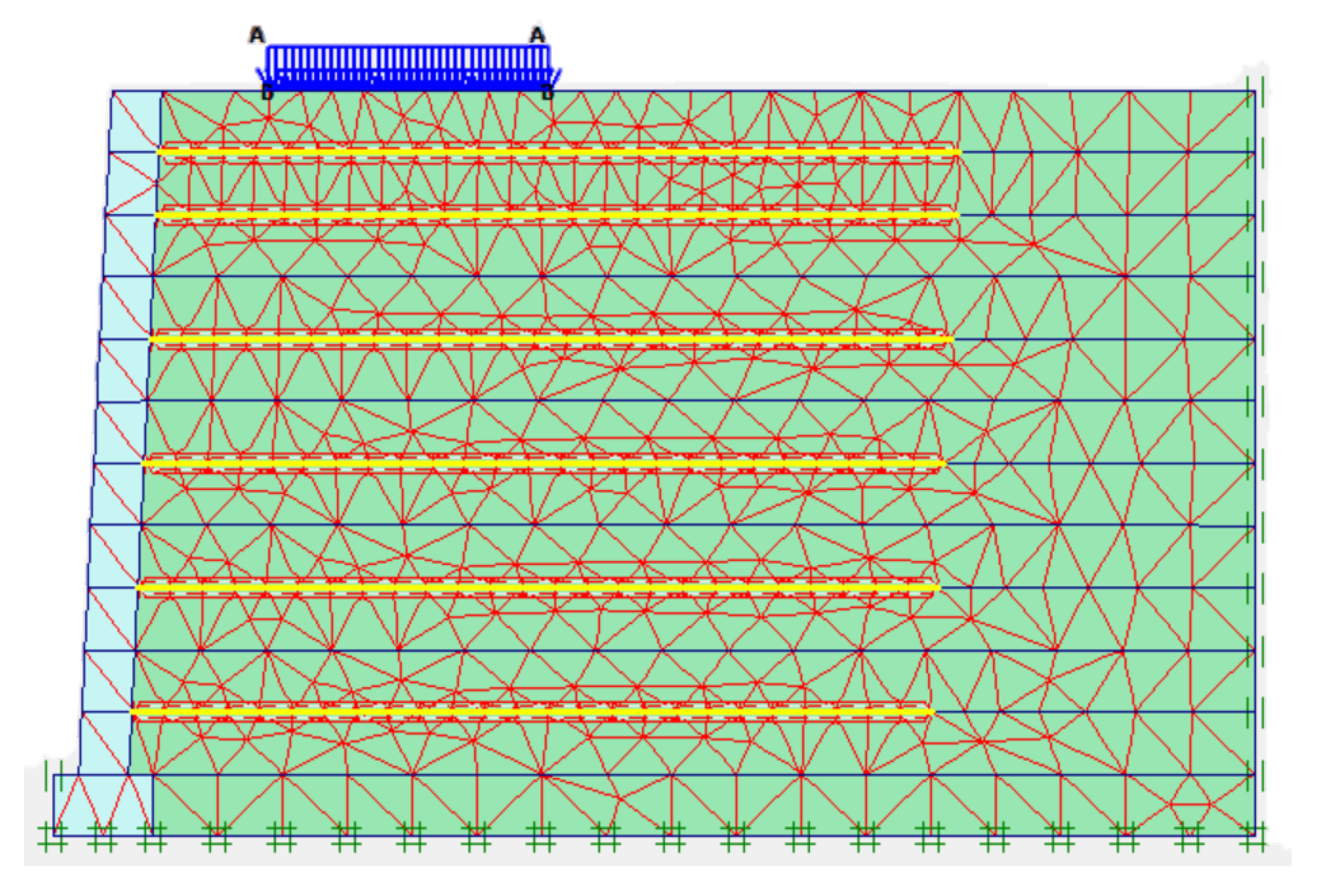
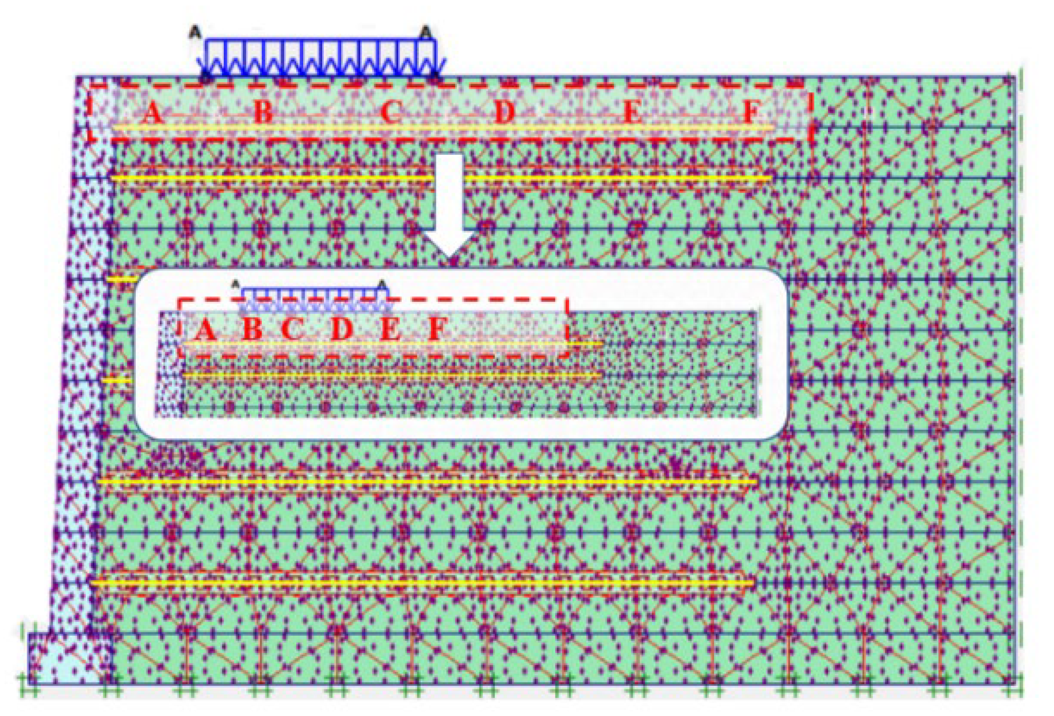
4.2. Model Building
4.3. Influencing Factors of the Stress Diffusion Angle
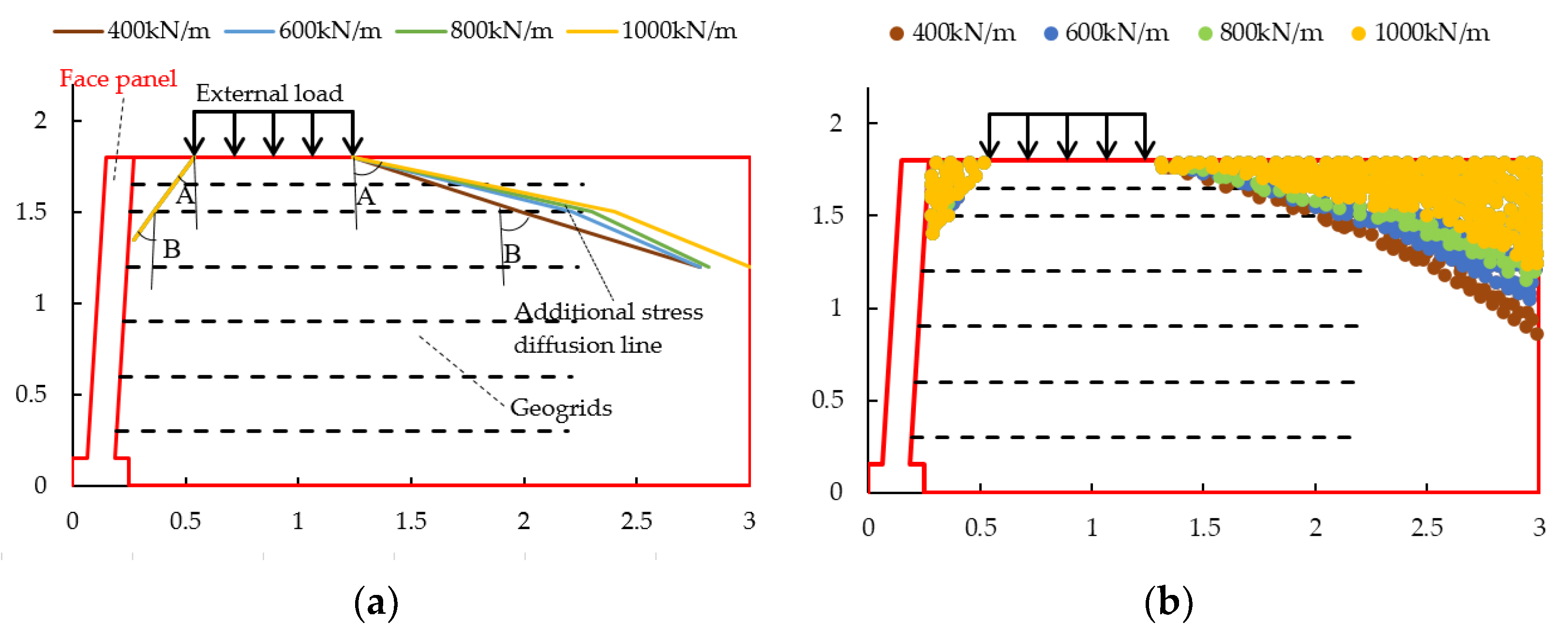
4.3.1. Influence of the Tensile Modulus of Reinforcement
4.3.2. Influence of Dynamic Stress Frequency
- With the increase in loading frequency, the stress diffusion angle near the wall panel did not change.
- The stress diffusion angle away from the wall panel increased gradually and the increase in the stress diffusion angle away from the wall panel was greater than that near the wall panel.
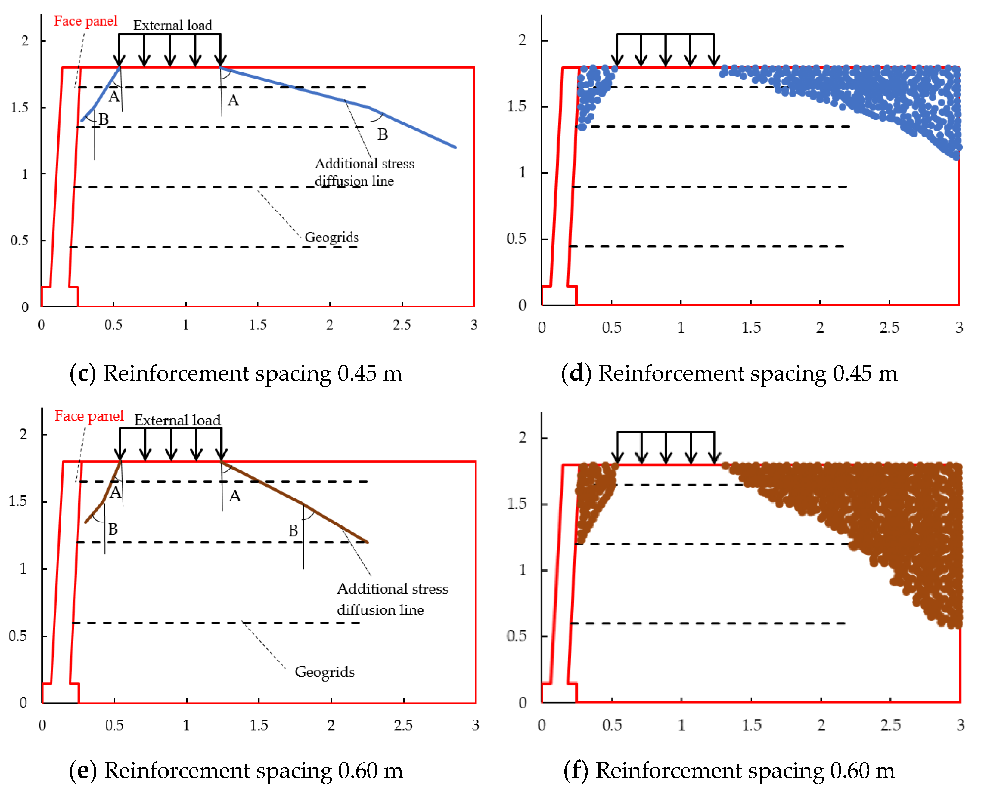
4.3.3. Influence of Reinforcement Spacing
- Diffusion angle A decreases with the increase in reinforcement spacing and diffusion angle B increases with the increase in reinforcement spacing.
- Near the panel, the stress diffusion range shows a trend of outward diffusion with the decrease in the retaining wall height, while away from the panel, the stress diffusion range shows a trend of inward contraction with the decrease in the retaining wall height.
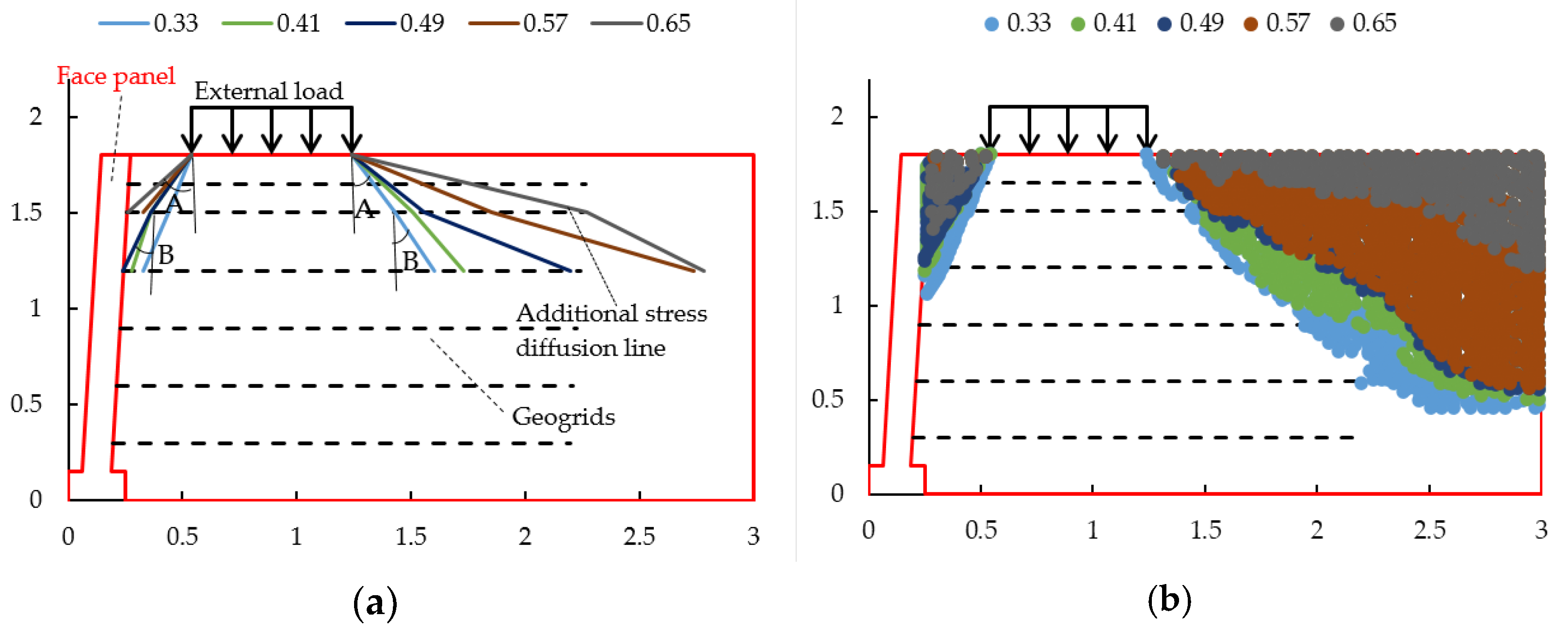
4.3.4. Influence of the Reinforcement–Soil Interaction
- The stress diffusion angle A increased with the increased coefficient of the reinforcement–soil. Although the diffusion angle B had a little bit of a decreased trend, the diffusion range still showed an increasing trend.
- With the increase in the interaction coefficient of the reinforcement–soil, the average increased for the stress diffusion Angle A near the wall was 25.99% and that away from the wall was 23.22%, indicating that the stress diffusion angle near the wall was more sensitive to the change in the interaction coefficient of the reinforcement–soil.
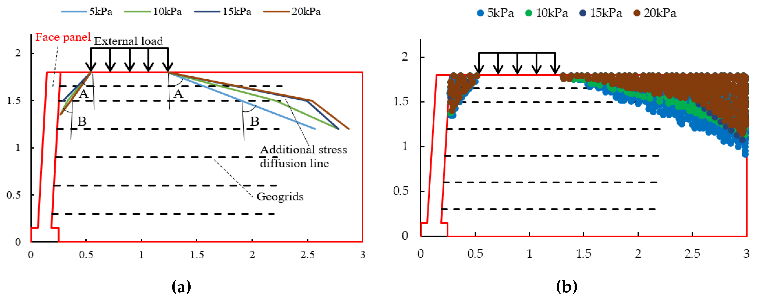
4.3.5. Influence of Dynamic Stress Amplitude
- The stress diffusion for angle A on the side close to the panel increased with the increase in the dynamic stress amplitude and, when the dynamic stress amplitude reached 20 kPa, the diffusion angle A tended to decrease; the diffusion angle B had no obvious regular change.
- The stress diffusion for angle A on the side away from the panel increased with the increase in the dynamic stress amplitude and the diffusion angle B decreased with the increase in the dynamic stress amplitude, but the diffusion range still tended to expand.
5. Discussion
6. Conclusions
- The mean value of the vertical dynamic earth pressure caused by the external load was non-linearly distributed with the height of the retaining wall, decaying from top to bottom. The decay rate at the top was 14.9% smaller than that at the bottom, which was 58.54%, and increased with the increase in the loading amplitude, while the loading frequency and number of loading cycles had no obvious effect on the mean value of the vertical dynamic earth pressure caused by the external load.
- The diffusion angle of the stress caused by the external load of the reinforced body was basically between 50° and 65° in the range from 1.8 m to 1.2 m. The diffusion angle at the top of the retaining wall was slightly larger than that at the middle; the stress diffusion angle at the side near the panel was smaller than that at the side away from the panel. The stress diffusion angle increased with the increase in the loading amplitude and had no obvious change with the increase in the loading frequency. The rule was consistent with the numerical simulation results. The stress diffusion angle reaches the maximum value at the loading amplitude of 60–80kPa and dynamic stress frequency of 4 Hz.
- The stress diffusion range of the reinforced soil retaining wall increased with the increase in the coefficient of the reinforcement—soil, dynamic stress amplitude, dynamic stress frequency, and tensile modulus of the reinforcement material; it decreased with an increase in the reinforcement spacing.
- With the change in the coefficient of reinforcement–soil, dynamic stress amplitude, dynamic stress frequency, tensile modulus of reinforcement, and the spacing of reinforcement. The average variation amplitude of stress diffusion angle A was 24.6%, 12.02%, 0.52%, 1.83%, and 5.61%, respectively. The main factors affecting the stress diffusion in reinforced soil retaining walls were the coefficient of reinforcement–soil and the dynamic stress amplitude. The second factor was the tensile modulus of the reinforcement and the dynamic stress frequency, with the reinforcement spacing having less influence. The change in the stress diffusion was more obvious with the change in parameters on the side away from the panel than on the side near the panel.
Author Contributions
Funding
Institutional Review Board Statement
Informed Consent Statement
Data Availability Statement
Conflicts of Interest
References
- Wang, H.; Yang, G.Q.; Xiong, B.L. An experimental study of the structural behavior of reinforced soil retaining wall with concrete-block panel. Rock Soil Mech. 2016, 37, 487–498. [Google Scholar]
- Wu, L.H.; Yang, G.Q.; Zhang, Q.B. In-situ test on dynamic responses of reinforced soil retaining walls for high-speed railways. J. Southwest Jiaotong Univ. 2017, 52, 546–553. [Google Scholar]
- Pham, H.V.; Dias, D.; Dudchenko, A. 3D modeling of geosynthetic-reinforced pile-supported embankment under cyclic loading. Geosynth. Int. 2018, 27, 157–169. [Google Scholar] [CrossRef]
- Aqoub, K.; Mohamed, M.; Sheehan, T. Analysis of unreinforced and reinforced shallow piled embankments under cyclic loading. Geosynth. Int. 2019, 27, 182–199. [Google Scholar] [CrossRef]
- Aqoub, K.; Mohamed, M.; Sheehan, T. Quantitative analysis of shallow unreinforced and reinforced piled embankments with different heights subject to cyclic loads: Experimental study. Soil Dyn. Earthq. Eng. 2020, 138, 106277. [Google Scholar] [CrossRef]
- Wang, J.Q.; Xu, L.J.; Li, Y.Y. Influence of dynamic loading frequency on dynamic characteristics of geogrid reinforced soil retaining walls. J. Vib. Eng. 2019, 32, 898–907. [Google Scholar]
- Wang, J.Q.; Xu, L.J.; Huang, S.B. Analysis of bearing behavior of geogrid reinforced abutment retaining wall under dynamic load. Rock Soil Mech. 2019, 40, 4220–4228+4269. [Google Scholar]
- Wang, J.Q.; Xu, L.J.; Xue, J.F. Laboratory study on geogrid reinforced soil wall with modular facing under cyclic strip loading. Arab. J. Geosci. 2020, 13, 70–83. [Google Scholar] [CrossRef]
- Xiao, C.Z.; Gao, S.; Li, H.Q. Experimental study on performance of multi-tiered geogrid reinforced soil retaining wall under uniform static load. J. Eng. Geol. 2020, 28, 1359–1367. [Google Scholar]
- Fattah Mohammed, Y.; Salim Nahla, M.; Ismaiel Mohammad, S. Influence of Geogrid Reinforcement of Sand in Transfer of Dynamic Loading to Underground Structure. Earth Environ. Sci. 2021, 856, 012013. [Google Scholar]
- Kargar, M.; Mir Mohammad Hosseini, S.M. Earth pressure distribution behind rigid non-yielding walls under the effect of repeated loading on backfill. Arab. J. Geosci. 2015, 8, 839–847. [Google Scholar] [CrossRef]
- Ding, G.Y.; Wu, J.L.; Wang, J. Experimental study on vibration reduction by using soilbag cushions under traffic loads. Geosynth. Int. 2018, 25, 322–333. [Google Scholar] [CrossRef]
- Luo, X.W.; Lu, Z.; Yao, H.L. Experimental study on soft rock subgrade reinforced with geocell. Road Mater. Pavement Des. 2022, 23, 2190–2204. [Google Scholar] [CrossRef]
- Zhang, T. Study on dynamic characteristics of subgrade filler under vehicle load. Water Sci. Eng. 2022, 2, 78–82. [Google Scholar]


| Items | Indexes |
|---|---|
| Name | Gravel soil |
| Coefficient uniformity (Cu) | 17.48 |
| Coefficient curvature (Cc) | 0.54 |
| Internal friction angle (°) | 35 |
| Maximum dry density (g/cm3) | 2.31 |
| Optimum moisture content (%) | 8.7 |
| Items | Indexes |
|---|---|
| Tensile strength (kN/m) | 39.69 |
| Tensile strength @ 2% strain (kN/m) | 12.3 |
| Tensile strength @ 5% strain (kN/m) | 24.5 |
| Axial peak strain (%) | 11.5 |
| Name | Model | Measuring Range | Accuracy |
|---|---|---|---|
| Vibrating wire pressure cell | JMZX-5003A | 0.3 MPa | 0.001 MPa |
| Strain gauge pressure cell | BY-2, BY-3 | 0.3 MPa | 0.001 MPa |
| Items | Index |
|---|---|
| Coefficient of loose layer | 1.33 |
| Thickness of loose layer (cm) | 20.0 |
| Compaction thickness (cm) | 15.0 |
| Compaction times | 4.0 |
| Compaction degree (%) | ≥85 |
| Location | Dynamic Stress Amplitude (kPa) | Dynamic Stress Frequency (Hz) | Stress Diffusion Angle A (°) | Stress Diffusion Angle B (°) |
|---|---|---|---|---|
| Close to the panel | 60–80 kPa | 4 | 60.855 | 18.09 |
| 6 | 57.995 | 35.184 | ||
| 8 | 55.231 | 28.065 | ||
| 10 | 56.774 | 29.611 | ||
| 60–100 kPa | 4 | 52.992 | 25.174 | |
| 6 | 53.437 | 27.097 | ||
| 8 | 52.992 | 25.174 | ||
| 10 | 52.431 | 22.782 | ||
| 60–120 kPa | 4 | 49.800 | 19.477 | |
| 6 | 50.312 | 20.296 | ||
| 8 | 49.196 | 12.68 | ||
| 10 | 48.847 | 13.071 | ||
| Away from the panel | 60–80 kPa | 4 | 64.902 | 8.904 |
| 6 | 64.782 | 9.834 | ||
| 8 | 63.849 | 18.521 | ||
| 10 | 63.700 | 20.388 | ||
| 60–100 kPa | 4 | 62.303 | 17.311 | |
| 6 | 62.365 | 16.436 | ||
| 8 | 62.427 | 22.375 | ||
| 10 | 62.488 | 17.398 | ||
| 60–120 kPa | 4 | 61.542 | 10.074 | |
| 6 | 61.800 | 12.225 | ||
| 8 | 61.229 | 20.715 | ||
| 10 | 61.216 | 19.409 |
| Material | Constitutive Model | Axial Stiffness at 2% Strain/(kN·m−1) |
|---|---|---|
| Geogrid | Linear Elastic | 615 |
| Items | Filler | Wall Face and Face Footing |
|---|---|---|
| Name | Gravel soil | Concrete |
| Model | Mohr-Coulomb | Linear Elastic |
| Natural unit weight (kN/m3) | 18 | 23 |
| Saturated unit weight (kN/m3) | 18.5 | 25 |
| Cohesion (kPa) | 1 | - |
| Internal friction angle (°) | 35 | - |
| Young’s Modulus (MPa) | 50 | 3×10⁴ |
| Poisson ratio | 0.2 | 0.2 |
| Location | Tensile Modulus of Reinforcement (kN/m) | Stress Diffusion Angle A 1 (°) | Change Amplitude of the Diffusion Angle A/(%) | Stress Diffusion Angle B 2 (°) | Change Amplitude of the Diffusion Angle B/(%) |
|---|---|---|---|---|---|
| Close to the panel | 400 | 30.964 | - | 30.964 | - |
| 600 | 30.964 | 0 | 30.964 | 0 | |
| 800 | 30.964 | 0 | 30.964 | 0 | |
| 1000 | 30.964 | 0 | 30.964 | 0 | |
| Away from the panel | 400 | 65.964 | - | 66.194 | - |
| 600 | 72.814 | 10.38 | 75.256 | 13.69 | |
| 800 | 74.197 | 1.89 | 73.909 | 1.78 | |
| 1000 | 75.500 | 1.75 | 75.964 | 2.78 |
| Location | Dynamic Stress Frequency/Hz | Stress Diffusion Angle A 1/(°) | Change Amplitude of the Diffusion Angle A/(%) | Stress Diffusion Angle B 2/(°) | Change Amplitude of the Diffusion Angle B/(%) |
|---|---|---|---|---|---|
| Close to the panel | 4 | 30.964 | - | 28.072 | - |
| 6 | 30.964 | 0 | 28.072 | 0 | |
| 8 | 30.964 | 0 | 28.072 | 0 | |
| 10 | 30.964 | 0 | 28.072 | 0 | |
| Away from the panel | 4 | 76.504 | - | 44.029 | - |
| 6 | 76.504 | 0 | 47.726 | 8.39 | |
| 8 | 76.504 | 0 | 56.310 | 17.98 | |
| 10 | 76.908 | 0.53 | 56.889 | 1.02 |
| Location | Reinforcement Spacing (cm) | Stress Diffusion Angle A 1 (°) | Change Amplitude of the Diffusion Angle A/(%) | Stress Diffusion Angle B 2 (°) | Change Amplitude of the Diffusion Angle B/(%) |
|---|---|---|---|---|---|
| Close to the panel | 30 | 30.993 | - | 18.435 | - |
| 45 | 28.072 | 9.42 | 21.801 | 18.26 | |
| 60 | 25.017 | 10.88 | 28.072 | 28.76 | |
| Away from the panel | 30 | 76.504 | - | 59.534 | - |
| 45 | 76.075 | 0.56 | 58.523 | 1.70 | |
| 60 | 74.876 | 1.58 | 60.018 | 2.55 |
| Location | Coefficient of Reinforcement–Soil | Stress Diffusion Angle A 1/(°) | Change Amplitude of the Diffusion Angle A/(%) | Stress Diffusion Angle B 2/(°) | Change Amplitude of the Diffusion Angle B/(%) |
|---|---|---|---|---|---|
| Close to the panel | 0.33 | 18.435 | - | 20.136 | - |
| 0.41 | 30.964 | 67.96 | 14.931 | 25.85 | |
| 0.49 | 30.964 | 0 | 21.890 | 46.61 | |
| 0.57 | 34.923 | 12.79 | - | - | |
| 0.65 | 43.025 | 23.20 | - | - | |
| Away from the panel | 0.33 | 32.421 | - | 29.461 | - |
| 0.41 | 42.044 | 29.68 | 36.187 | 22.83 | |
| 0.49 | 46.896 | 11.54 | 64.728 | 78.87 | |
| 0.57 | 63.832 | 36.11 | 71.362 | 10.25 | |
| 0.65 | 73.761 | 15.55 | 59.534 | 16.57 |
| Location | Dynamic Load Amplitude/kPa | Stress Diffusion Angle A 1/(°) | Change Amplitude of the Diffusion Angle A/(%) | Stress Diffusion Angle B 2/(°) | Change Amplitude of the Diffusion Angle B/(%) |
|---|---|---|---|---|---|
| Close to the panel | 5 | 30.964 | - | 21.801 | - |
| 10 | 34.992 | 13.01 | 30.964 | 42.03 | |
| 15 | 39.806 | 13.76 | - | - | |
| 20 | 30.964 | 22.21 | 30.964 | - | |
| Away from the panel | 5 | 65.556 | - | 65.879 | |
| 10 | 72.814 | 11.07 | 62.241 | 5.52 | |
| 15 | 76.504 | 5.07 | 44.029 | 29.26 | |
| 20 | 76.504 | 0 | 44.029 | 0 |
Publisher’s Note: MDPI stays neutral with regard to jurisdictional claims in published maps and institutional affiliations. |
© 2022 by the authors. Licensee MDPI, Basel, Switzerland. This article is an open access article distributed under the terms and conditions of the Creative Commons Attribution (CC BY) license (https://creativecommons.org/licenses/by/4.0/).
Share and Cite
Wang, H.; Wang, N.; Yang, G.; Ma, J. Model Test and Numerical Simulation Research of Reinforced Soil Retaining Walls under Cyclic Loads. Sustainability 2022, 14, 15643. https://doi.org/10.3390/su142315643
Wang H, Wang N, Yang G, Ma J. Model Test and Numerical Simulation Research of Reinforced Soil Retaining Walls under Cyclic Loads. Sustainability. 2022; 14(23):15643. https://doi.org/10.3390/su142315643
Chicago/Turabian StyleWang, He, Nan Wang, Guangqing Yang, and Jian Ma. 2022. "Model Test and Numerical Simulation Research of Reinforced Soil Retaining Walls under Cyclic Loads" Sustainability 14, no. 23: 15643. https://doi.org/10.3390/su142315643
APA StyleWang, H., Wang, N., Yang, G., & Ma, J. (2022). Model Test and Numerical Simulation Research of Reinforced Soil Retaining Walls under Cyclic Loads. Sustainability, 14(23), 15643. https://doi.org/10.3390/su142315643