
Analytical Design of Synchrophasor Communication Networks with Resiliency Analysis Framework for Smart Grid


Abstract
1. Introduction
2. Related Work and Motivation
2.1. Related Work
2.2. Motivation
2.3. Contribution
- The proposed work presents a mathematical modelling of the SCN pertaining to the SG.
- The design perspective of a SCN is presented spanning communication infrastructures, communication protocols, and communication technologies.
- A resiliency analysis framework, including resiliency estimation metrics, is proposed. The resiliency framework is based on both key parameters: hardware reliability and data reliability, ensuring a wide perspective of disturbances for resiliency analysis.
- The proposed resiliency framework is validated for resiliency analysis of a SCN pertaining a practical power grid of India, (West Bengal State) as a case study.
3. System Model and Parametrization
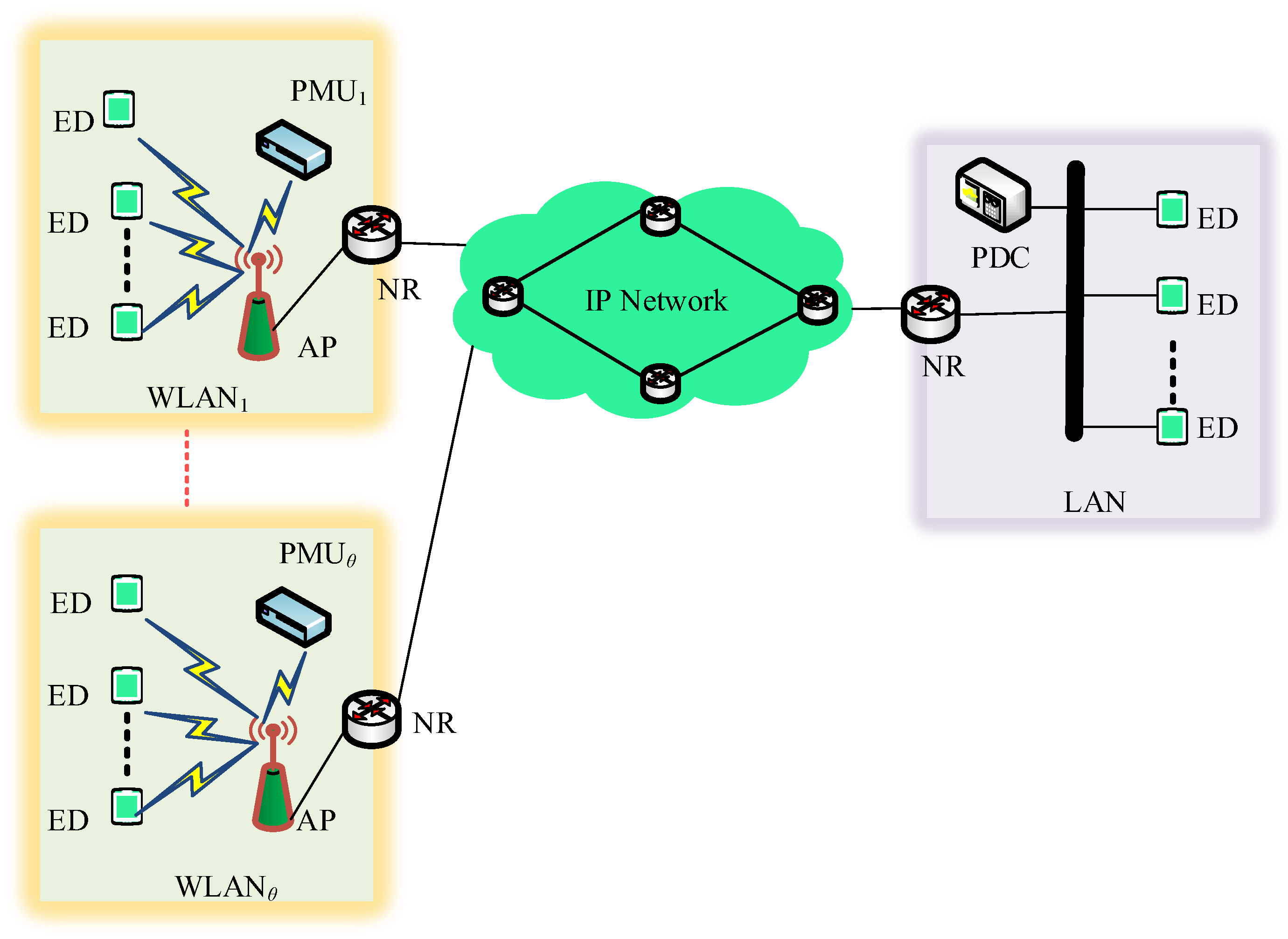
3.1. System Modelling
3.2. Design of Hybrid SCN
4. Comprehensive Resiliency Analysis Framework
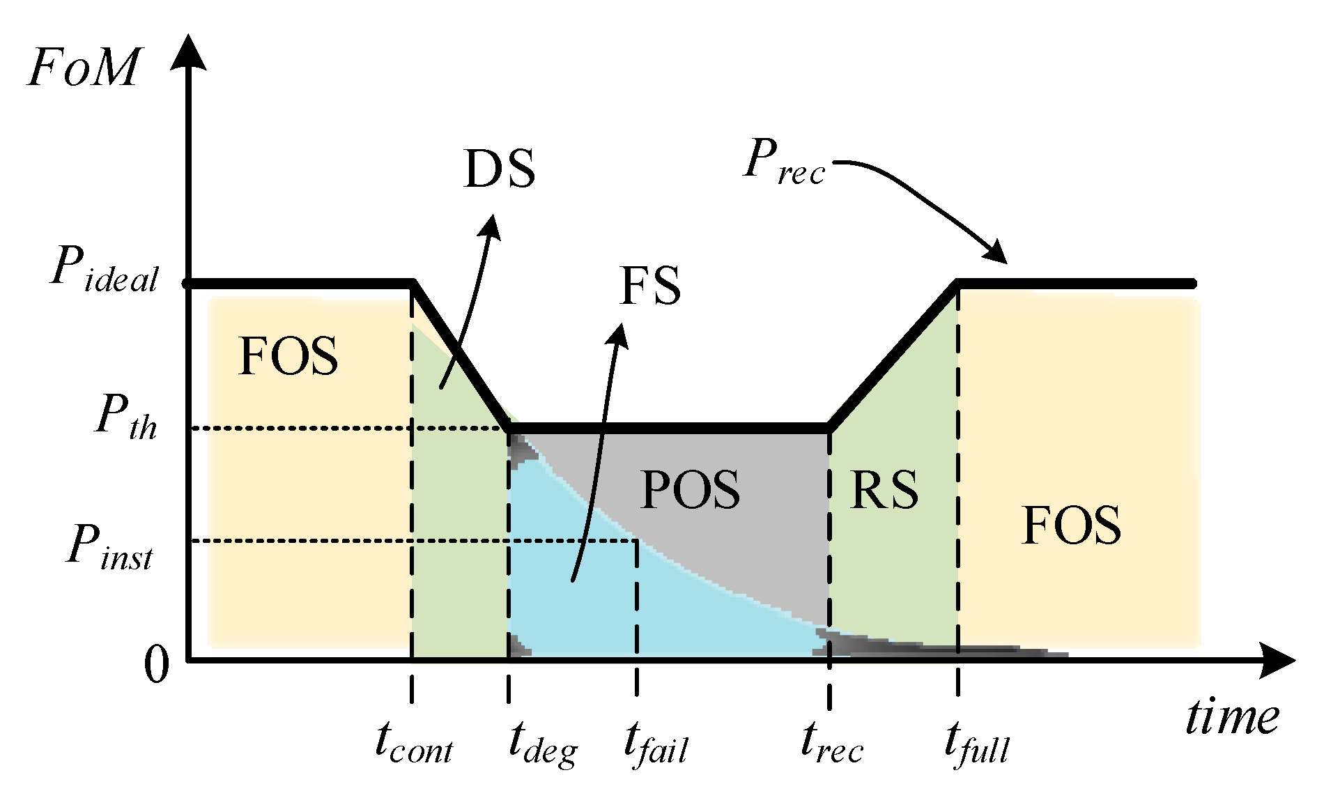
4.1. Resiliency Framework
4.2. Resiliency Metric
5. Parameters for Resiliency Analysis of Hybrid SCN
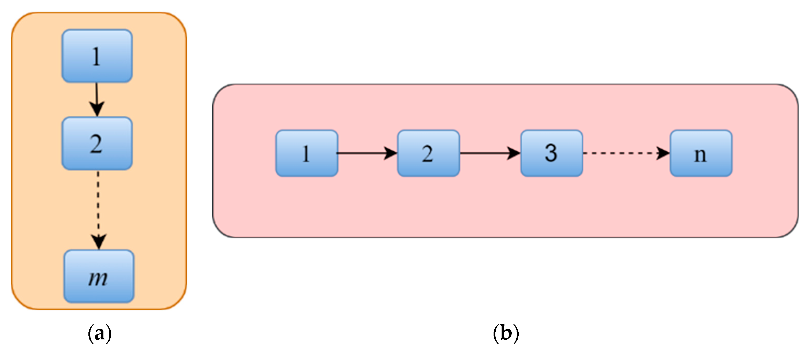
5.1. Reliability Analysis of Series and Parallel Configures System
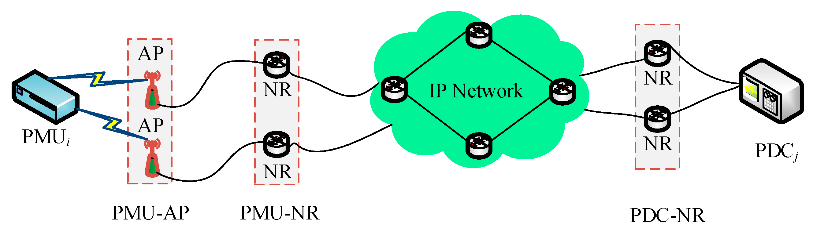
5.2. Hardware Reliability for Hybrid SCN
5.3. Data Reliability of Hybrid SCN
5.4. Resiliency Metrics for Hybrid SCN
6. Resiliency Analysis of Hybrid SCN
6.1. Simulation Framework
6.2. Simulation Results and Discussions
6.3. Resiliency Metrics for WASA
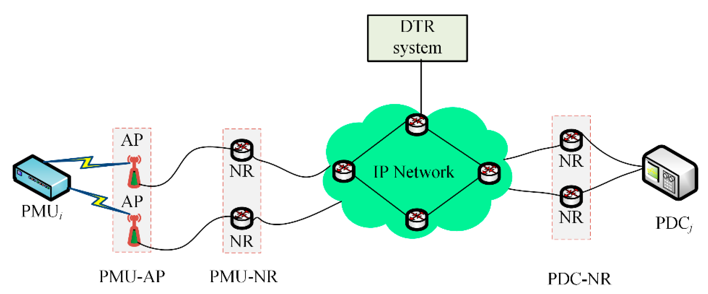
6.4. Resiliency Metric for DTR SCN Model
7. Conclusions
Author Contributions
Funding
Conflicts of Interest
References
- International Energy Outlook 2020. 2020. Available online: https://www.eia.gov/outlooks/ieo/ (accessed on 30 September 2022).
- Jha, A.V.; Appasani, B.; Ghazali, A.N. Analytical Channel Modelling of Synchrophsor Communication Networks in a Smart Grid Cyber Physical System. In Proceedings of the 2021 3rd Global Power, Energy and Communication Conference (GPECOM), Antalya, Turkey, 5–8 October 2021; pp. 257–262. [Google Scholar] [CrossRef]
- Haes Alhelou, H.; Hamedani-Golshan, M.E.; Njenda, T.C.; Siano, P. A Survey on Power System Blackout and Cascading Events: Research Motivations and Challenges. Energies 2019, 12, 682. [Google Scholar] [CrossRef]
- Usman, M.U.; Faruque, M.O. Applications of synchrophasor technologies in power systems. J. Mod. Power Syst. Clean Energy 2018, 7, 211–226. [Google Scholar] [CrossRef]
- Chawla, A.; Aftab, M.A.; Hussain, S.S.; Panigrahi, B.K.; Ustun, T.S. Cyber–physical testbed for Wide Area Measurement System employing IEC 61850 and IEEE C37. 118 based communication. Energy Rep. 2022, 8, 570–578. [Google Scholar] [CrossRef]
- Jimada-Ojuolape, B.; Teh, J. Impacts of Communication Network Availability on Synchrophasor-Based DTR and SIPS Reliability. IEEE Syst. J. 2021, 1–12. [Google Scholar] [CrossRef]
- Jimada-Ojuolape, B.; Teh, J. Surveys on the reliability impacts of power system cyber–physical layers. Sustain. Cities Soc. 2020, 62, 102384. [Google Scholar] [CrossRef]
- Krishna, R.R.; Priyadarshini, A.; Jha, A.V.; Appasani, B.; Srinivasulu, A.; Bizon, N. State-of-the-Art Review on IoT Threats and Attacks: Taxonomy, Challenges and Solutions. Sustainability 2021, 13, 9463. [Google Scholar] [CrossRef]
- Katsaros, K.V.; Yang, B.; Chai, W.K.; Pavlou, G. Low latency communication infrastructure for synchrophasor applications in distribution networks. In Proceedings of the 2014 IEEE International Conference on Smart Grid Communications (SmartGridComm), Venice, Italy, 3–6 November 2014; pp. 392–397. [Google Scholar]
- Appasani, B.; Jha, A.V.; Mishra, S.K.; Ghazali, A.N. Communication infrastructure for situational awareness enhancement in WAMS with optimal PMU placement. Prot. Control Mod. Power Syst. 2021, 6, 1–12. [Google Scholar] [CrossRef]
- Jha, A.V.; Appasani, B.; Ghazali, A.N. A Comprehensive Framework for the Assessment of Synchrophasor Communication Networks from the Perspective of Situational Awareness in a Smart Grid Cyber Physical System. Technol. Econ. Smart Grids Sustain. Energy 2022, 7, 1–18. [Google Scholar] [CrossRef]
- Farooq, S.M.; Hussain, S.M.S.; Kiran, S.; Ustun, T.S. Certificate Based Authentication Mechanism for PMU Communication Networks Based on IEC 61850-90-5. Electronics 2018, 7, 370. [Google Scholar] [CrossRef]
- Farooq, S.M.; Nabirasool, S.; Kiran, S.; Hussain, S.S.; Ustun, T.S. MPTCP based mitigation of denial of service (DoS) attack in PMU communication networks. In Proceedings of the 2018 IEEE International Conference on Power Electronics, Drives and Energy Systems (PEDES), Chennai, India, 18–21 December 2019; pp. 1–5. [Google Scholar]
- Holling, C.S. Resilience and Stability of Ecological Systems. Annu. Rev. Ecol. Syst. 1973, 4, 1–23. [Google Scholar] [CrossRef]
- Southwick, S.M.; Bonanno, G.A.; Masten, A.S.; Panter-Brick, C.; Yehuda, R. Resilience definitions, theory, and challenges: Interdisciplinary perspectives. Eur. J. Psychotraumatol. 2014, 5, 25338. [Google Scholar] [CrossRef] [PubMed]
- Hosseini, S.; Barker, K.; Ramirez-Marquez, J.E. A review of definitions and measures of system resilience. Reliab. Eng. Syst. Saf. 2016, 145, 47–61. [Google Scholar] [CrossRef]
- Jena, P.K.; Ghosh, S.; Koley, E. Identification of Optimal Sensor Location Based on Trade-Off Approach to Improve Resiliency of Electricity Market in Smart Grid. IEEE Sens. J. 2021, 21, 17271–17281. [Google Scholar] [CrossRef]
- Tushar; Venkataramanan, V.; Srivastava, A.; Hahn, A. CP-TRAM: Cyber-Physical Transmission Resiliency Assessment Metric. IEEE Trans. Smart Grid 2020, 11, 5114–5123. [Google Scholar] [CrossRef]
- Liu, G.; Ben Ollis, T.; Zhang, Y.; Jiang, T.; Tomsovic, K. Robust Microgrid Scheduling With Resiliency Considerations. IEEE Access 2020, 8, 153169–153182. [Google Scholar] [CrossRef]
- Bedoya, J.C.; Wang, Y.; Liu, C.-C. Distribution System Resilience Under Asynchronous Information Using Deep Reinforcement Learning. IEEE Trans. Power Syst. 2021, 36, 4235–4245. [Google Scholar] [CrossRef]
- Borghei, M.; Ghassemi, M.; Liu, C.C. Optimal capacity and placement of microgrids for resiliency enhancement of distribution networks under extreme weather events. In Proceedings of the 2020 IEEE Power & Energy Society Innovative Smart Grid Technologies Conference (ISGT), Washington, DC, USA, 17–20 February 2020; pp. 1–5. [Google Scholar]
- AlMajali, A.; Viswanathan, A.; Neuman, C. Analyzing Resiliency of the Smart Grid Communication Architectures under Cyber Attack. In CSET 12: Proceedings of the 5th USENIX conference on Cyber Security Experimentation and Test, Bellevue, WA, USA, 6 August 2012; USENIX Association: Berkeley, CA, USA, 2012. [Google Scholar]
- Jakaria, A.H.M.; Rahman, M.A.; Gokhale, A. Resiliency-Aware Deployment of SDN in Smart Grid SCADA: A Formal Synthesis Model. IEEE Trans. Netw. Serv. Manag. 2021, 18, 1430–1444. [Google Scholar] [CrossRef]
- Al Mtawa, Y.; Haque, A. Clustering-Coefficient Based Resiliency Approach for Smart Grid. In Proceedings of the 2021 International Wireless Communications and Mobile Computing (IWCMC), Harbin City, China, 28 June–2 July 2021; pp. 1569–1574. [Google Scholar]
- Ibrahim, M.; Alkhraibat, A. Resiliency Assessment of Microgrid Systems. Appl. Sci. 2020, 10, 1824. [Google Scholar] [CrossRef]
- Saad, A.; Faddel, S.; Youssef, T.; Mohammed, O.A. On the implementation of IoT-based digital twin for networked microgrids resiliency against cyber attacks. IEEE Trans. Smart Grid 2020, 11, 5138–5150. [Google Scholar] [CrossRef]
- Tabar, V.S.; Ghassemzadeh, S.; Tohidi, S. Increasing resiliency against information vulnerability of renewable resources in the operation of smart multi-area microgrid. Energy 2021, 220, 119776. [Google Scholar] [CrossRef]
- Appasani, B.; Jha, A.V.; Swain, K.; Cherukuri, M.; Mohanta, D.K. Resiliency Estimation of Synchrophasor Communication Networks in a Wide Area Measurement System. Front. Energy Res. 2022, 10, 350. [Google Scholar] [CrossRef]
- Jha, A.V.; Appasani, B.; Ustun, T.S. Resiliency assessment methodology for synchrophasor communication networks in a smart grid cyber–physical system. Energy Rep. 2022, 8, 1108–1115. [Google Scholar] [CrossRef]
- Khalkho, A.M.; Mohanta, D.K. Operational Resiliency Enhancement Using Synchrophasor Measurement. In Advances in Smart Grid Automation and Industry 4.0; Springer: Singapore, 2021; pp. 613–621. [Google Scholar]
- Iftimie, I.A.; Huskaj, G. Strengthening the Cybersecurity of Smart Grids: The Role of Artificial Intelligence in Resiliency of Substation Intelligent Electronic Devices. In Proceedings of the 19th European Conference on Cyber Warfare and Security, a Virtual Conference, University of Chester, Chester, UK, 25–26 June 2020; Academic Conferences and Publishing International Limited: Oxfordshire, UK, 2020; pp. 143–150. [Google Scholar]
- Khediri, A.; Laouar, M.R.; Eom, S.B. Enhancing Resiliency Feature in Smart Grids through a Deep Learning Based Prediction Model. Recent Adv. Comput. Sci. Commun. (Former. Recent Patents Comput. Sci.) 2020, 13, 508–518. [Google Scholar] [CrossRef]
- Singh, V.K.; Vaughan, E.; Rivera, J. SHARP-Net: Platform for Self-Healing and Attack Resilient PMU Networks. In Proceedings of the 2020 IEEE Power & Energy Society Innovative Smart Grid Technologies Conference (ISGT), Washington, DC, USA, 17–20 February 2020; pp. 1–5. [Google Scholar]
- Ustun, T.S.; Farooq, S.M.; Hussain, S.M.S. Implementing Secure Routable GOOSE and SV Messages Based on IEC 61850-90-5. IEEE Access 2020, 8, 26162–26171. [Google Scholar] [CrossRef]
- IEEE Std C37118-2005; IEEE Standard for Synchrophasor Measurements for Power Systems. IEEE Std C371181-2011 Revis; IEEE: Piscataway, NJ, USA, 2011; pp. 1–61. [CrossRef]
- IEEE Std C37118-2005; IEEE Standard for Synchrophasor Data Transfer for Power Systems. IEEE Std C371182-2011 Revis; IEEE: Piscataway, NJ, USA, 2011; pp. 1–53. [CrossRef]
- Khan, R.; McLaughlin, K.; Laverty, D.; Sezer, S. IEEE c37. 118-2 synchrophasor communication framework-overview, cyber vulnerabilities analysis and performance evaluation. In Proceedings of the International Conference on Information Systems Security and Privacy, Rome, Italy, 19–21 February 2016; SciTePress: Setúbal, Portugal, 2016; Volume 2, pp. 167–178. [Google Scholar]
- IEC/IEEE 60255-118-1:2018; IEEE/IEC International Standard-Measuring Relays and Protection Equipment-Part 118-1: Synchrophasor for Power Sys-tems-Measurements. IEEE: New York, NY, USA, 2018; pp. 1–78. [CrossRef]
- IEEE Std C37.247-2019; IEEE Standard for Phasor Data Concentrators for Power Systems. IEEE: New York, NY, USA, 2019; pp. 1–44. [CrossRef]
- Jha, A.V.; Ghazali, A.N.; Appasani, B.; Ravariu, C.; Srinivasulu, A. Reliability analysis of smart grid networks Iincorporating hardware failures and packet loss. Rev. Roum. Sci. Tech. El 2021, 65, 245–252. [Google Scholar]
- QualNet Network Simulator-Keysight. Available online: https://www.keysight.com/us/en/assets/3122-1395/technical-overviews/QualNet-Network-Simulator.pdf (accessed on 7 November 2022).
- Metwaly, M.K.; Teh, J. Fuzzy Dynamic Thermal Rating System-Based SIPS for Enhancing Transmission Line Security. IEEE Access 2021, 9, 83628–83641. [Google Scholar] [CrossRef]
- Jimada-Ojuolape, B.; Teh, J. Composite Reliability Impacts of Synchrophasor-Based DTR and SIPS Cyber–Physical Systems. IEEE Syst. J. 2022, 16, 3927–3938. [Google Scholar] [CrossRef]


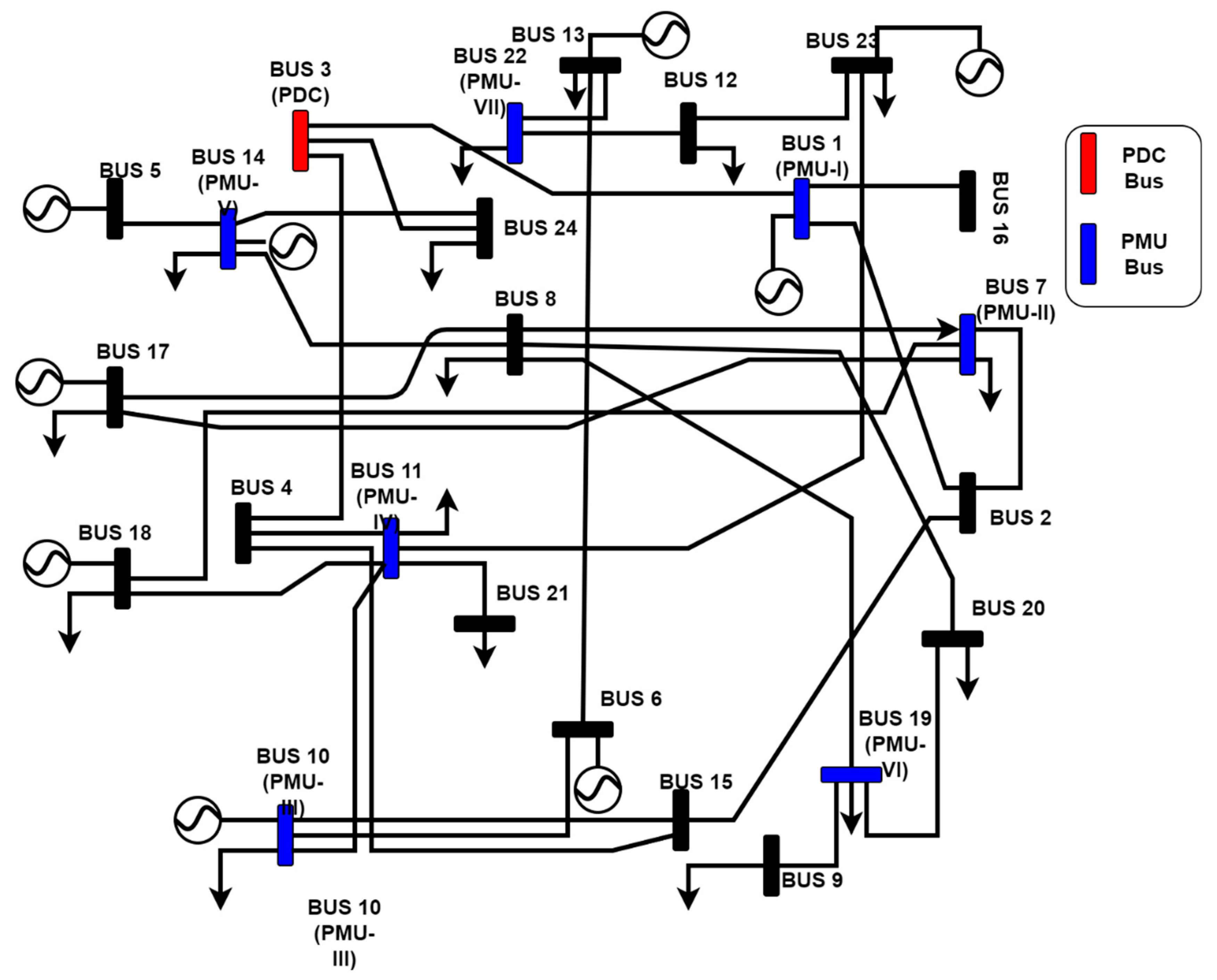
| Bus with a PMU | ID of PMU/PDC | Bus Locations | Distance from PDC (Km) | |
|---|---|---|---|---|
| Latitude | Longitude | |||
| Bus-1 | PMU-1 | 24.7828 | 87.9041 | 154.11 |
| Bus-3 | PDC-1 | 23.4814 | 87.4464 | - |
| Bus-7 | PMU-2 | 22.7494 | 88.5417 | 141.03 |
| Bus-10 | PMU-3 | 22.4442 | 87.8672 | 124.07 |
| Bus-11 | PMU-4 | 22.8361 | 87.9594 | 90.78 |
| Bus-14 | PMU-5 | 22.3997 | 88.2177 | 145.61 |
| Bus-19 | PMU-6 | 22.1188 | 88.3319 | 177.71 |
| Bus-22 | PMU-7 | 25.8502 | 87.8500 | 265.57 |
| Parameters | Values | |
|---|---|---|
| Coordinate System | Latitude | Longitude |
| SW Corner = 20.21 NE Corner = 30.41 | SW Corner = 73.57 NE Corner = 94.44 | |
| Altitude | 1500 m above mean sea level 0 m below mean sea level | |
| Weather mobility | 98 ms | |
| Node placement | As per geographical distribution of PMUs and PDCs | |
| Mobility model | Random walk for EDs | |
| PMU with DoS Attack | Degradation State | Recovery State | ||||||||||
|---|---|---|---|---|---|---|---|---|---|---|---|---|
| Pcont | tcont | Pdeg | tdeg | Prec | trec | Pfull | tfull | |||||
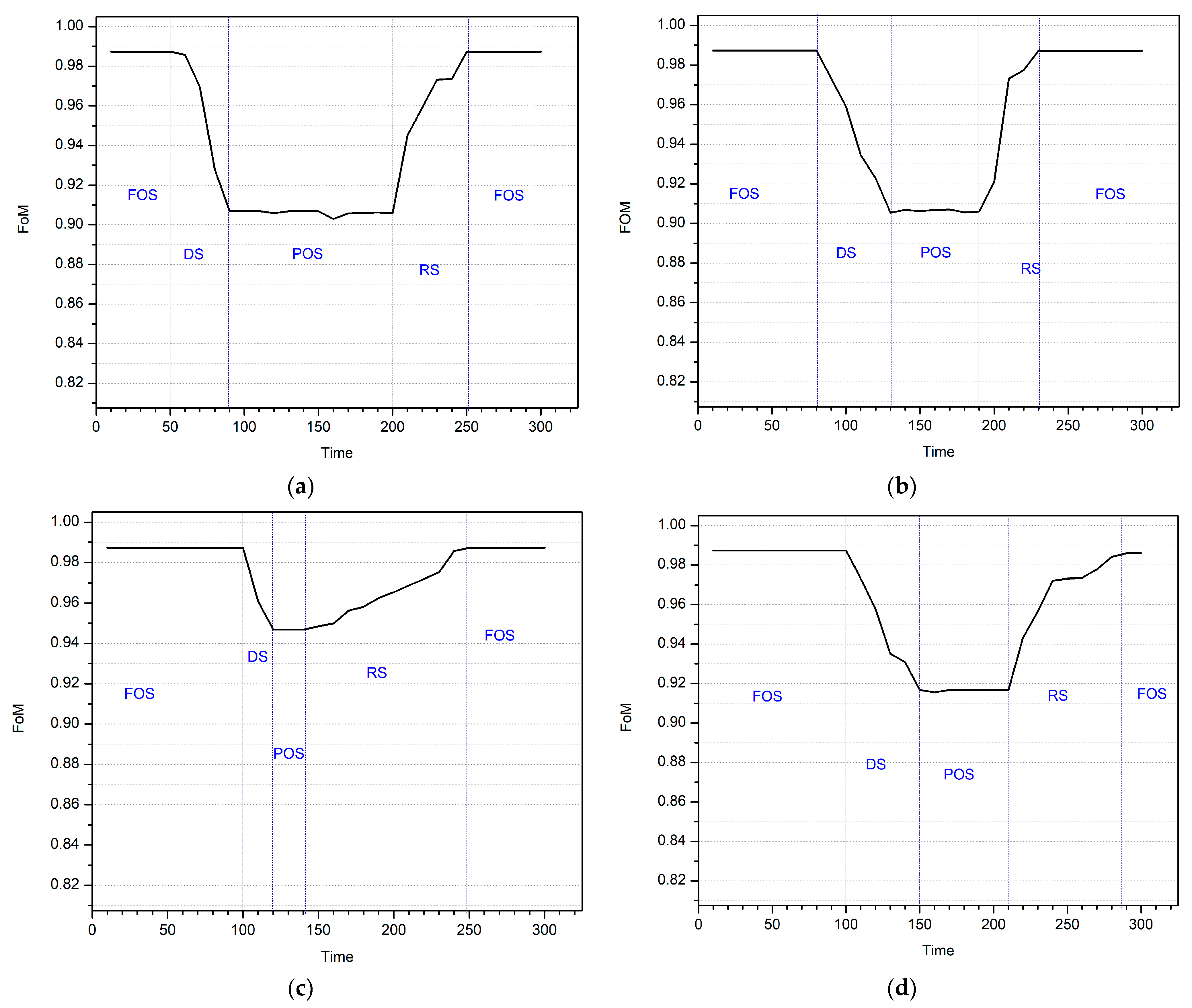
| PMU1 | 0.987639 | 0.985745 | 50 | 0.429894 | 0.906998 | 90 | 0.698939 | 0.944984 | 200 | 0.998939 | 0.987341 | 250 |
| PMU2 | 0.897155 | 0.973222 | 80 | 0.427155 | 0.906863 | 130 | 0.527155 | 0.920982 | 190 | 0.996521 | 0.987251 | 230 |
| PMU3 | 0.998939 | 0.987341 | 90 | 0.712439 | 0.946890 | 110 | 0.712439 | 0.946890 | 130 | 0.998939 | 0.987341 | 240 |
| PMU4 | 0.899277 | 0.973222 | 100 | 0.491277 | 0.915617 | 150 | 0.499299 | 0.916750 | 200 | 0.989277 | 0.985929 | 280 |
| PMU with DoS Attack | Degradation State | Recovery State | (per ms) | (per ms) | |||||||
|---|---|---|---|---|---|---|---|---|---|---|---|
| tcont | tdeg | trec | tfull | ||||||||
| PMU1 | 50 | 0.985745 | 90 | 0.906998 | 200 | 0.944984 | 250 | 0.987341 | 0.98736 | −1.97 | 0.85 |
| PMU2 | 80 | 0.973222 | 130 | 0.906863 | 190 | 0.920982 | 230 | 0.987251 | 0.98764 | −1.33 | 1.66 |
| PMU3 | 90 | 0.987341 | 110 | 0.946890 | 130 | 0.946890 | 240 | 0.987341 | 0.98734 | −2.02 | 0.37 |
| PMU4 | 100 | 0.973222 | 150 | 0.915617 | 200 | 0.916750 | 280 | 0.985929 | 0.98628 | −1.15 | 0.86 |
Publisher’s Note: MDPI stays neutral with regard to jurisdictional claims in published maps and institutional affiliations. |
© 2022 by the authors. Licensee MDPI, Basel, Switzerland. This article is an open access article distributed under the terms and conditions of the Creative Commons Attribution (CC BY) license (https://creativecommons.org/licenses/by/4.0/).
Share and Cite
Jha, A.V.; Appasani, B.; Gupta, D.K.; Ustun, T.S. Analytical Design of Synchrophasor Communication Networks with Resiliency Analysis Framework for Smart Grid. Sustainability 2022, 14, 15450. https://doi.org/10.3390/su142215450
Jha AV, Appasani B, Gupta DK, Ustun TS. Analytical Design of Synchrophasor Communication Networks with Resiliency Analysis Framework for Smart Grid. Sustainability. 2022; 14(22):15450. https://doi.org/10.3390/su142215450
Chicago/Turabian StyleJha, Amitkumar V., Bhargav Appasani, Deepak Kumar Gupta, and Taha Selim Ustun. 2022. "Analytical Design of Synchrophasor Communication Networks with Resiliency Analysis Framework for Smart Grid" Sustainability 14, no. 22: 15450. https://doi.org/10.3390/su142215450
APA StyleJha, A. V., Appasani, B., Gupta, D. K., & Ustun, T. S. (2022). Analytical Design of Synchrophasor Communication Networks with Resiliency Analysis Framework for Smart Grid. Sustainability, 14(22), 15450. https://doi.org/10.3390/su142215450