Article

Characteristics of Mining-Induced Slope Movement and Ground Behavior under Gully Landforms

1
Chongqing Vocational Institute of Engineering, Chongqing 402260, China
2
China Coal Technology Engineering Group Chongqing Research Institute, Chongqing 400039, China
*
Author to whom correspondence should be addressed.
Sustainability 2022, 14(21), 13941; https://doi.org/10.3390/su142113941
Submission received: 22 August 2022 / Revised: 12 October 2022 / Accepted: 24 October 2022 / Published: 26 October 2022
(This article belongs to the Collection Mine Hazards Identification, Prevention and Control)

Abstract

:
Exploring the phenomenon of surface cracks and the abnormal phenomenon of ground behavior during coal mining under gully landforms, laboratory physical similarity simulation models were established to study the movement characteristics and ground behavior laws of working faces of different mining methods under gully landforms. The results indicate that in cases when a roadway is situated below the top of the slope, the corresponding deformation of the surrounding rock of the roadway is aggravated by the mining stress. Furthermore, when a roadway is located below the base of the gully, it is less affected by mining; thus, it could remain relatively stable. The ground behavior laws of working faces in gully geomorphology areas are associated with the position of the working face and the direction of working: when mining towards the gully, the ground behavior appeared relatively gentle and the surface slipped towards the gully; when mining away from the gully, the ground behavior appeared intense, the pressure was sudden and short, and with the increase in overburden thickness, the interval distance periodically decreased. When a working face passes through a gully, dumping of the hydraulic support should be prevented in the section of mining towards the gully; in sections of mining away from gully, the support strength should be strengthened to prevent the support and other equipment from being crushed. In actual mining, mining towards a gully should be adopted as much as possible in the stoping of the working face. In this way, the ground behavior is gentle, the interval distance periodical weight is longer, and the advance abutment pressure is small.

1. Introduction

With the reduction in coal resources in the east, China’s coal mining has gradually shifted to the west. Taking Shanxi Province as an example, coalfields are distributed in 40% of the land in the region. Due to the large number and thickness of coal seams, as well as the excellent coal quality [1], Shanxi Province has attracted worldwide attention and has become an energy base for national economic development [2,3]. Most of the coal fields in Shanxi are medium-thick coal seams with shallow burial and good mining conditions. With the advancement of mining technology and equipment, most coal mines utilize fully mechanized caving. Many scholars have conducted in-depth research on the characteristics of overlying strata movement, surface motion characteristics, and ore pressure behavior under fully mechanized caving mining conditions [4,5].
Some researchers have analyzed the coal seam overlying strata movement and strata behavior regularity of coal seam under fully mechanized caving mining conditions by numerical simulation and similar material simulation. For example, the deformation and failure of surrounding rocks and stress transfer at different roof thicknesses was analyzed using three-dimensional modeling software through a combination of numerical modeling and analogue modeling [6,7]. A macro stress shell was developed for high-stress bunches in the surrounding rocks [8,9], and a physical model analyzed the influence of barrier pillars on overburden failure at the working face [10]. Patterns of overburden movement at a working face with a large mining height were determined using numerical simulations [11,12], and the deformation and failure mechanisms of front top coal were used to propose the caving number [13]. Furthermore, a dynamic balance arch structure was formed using the roof and surrounding rock in the working face [14] and the relationship of roof fall and rib spalling with support parameters. The structure of an immediate roof studied in mechanical equilibrium revealed the formation mechanism [15]; some researchers conducted the on-site monitoring of mine pressure on a fully mechanized caving face [16,17] and analyzed the mine pressure data and the laws of overlying strata under different conditions [18,19].
In mining-induced surface deformation movements [20,21], there were several notable studies related to the surface slope movement induced by underground mining [22,23], conducted in two scenarios [24,25]: underground mining in a mountain area, and the simultaneous operations of underground mining and surface mining [26,27].Due to surface subsidence caused by underground mining, it is possible to induce landslides under certain geological [28,29], topographical, and natural conditions. These are referred to as mining landslides [30,31]. The reasons for the occurrence of mining landslides are as follows: surface cracks in the goaf, mountain landforms, geological structures, atmospheric precipitation or snow melting, work surface layout, etc.
Most contemporary studies have focused on the influence of underground mining on surface movement, overburden movement, and mine pressure characteristics [32]. However, there are few studies on the influence of geomorphic features of surface undulations on underground mining [33]. It is generally believed that it is easy to mine in medium- and shallow-buried coal fields; thus, the influences of surface fluctuations on mine pressure are ignored [34]. Some data and experiments have shown that the ore pressure under uneven landforms appears to be sensitive and more intense under certain conditions, which makes the mine pressure appear more prominent [35].
Coalfields in western China exhibit a small depth of occurrence and diverse topography. Compared with southwest coalfields, the surface vegetation of northwest coalfields is sparse, the soil and water conservation ability is weak, the surface water erosion is serious, the gullies are vertical and horizontal, the slope body changes greatly, the terrain is fragmented, and the relative height difference is more than 100 m. The typical landform of the area is shown in Figure 1. The influence of landforms on underground mining is clear and sometimes even plays a leading role. The phenomena of sudden, strong ground pressure during the mining of some working faces, large-scale caving due to overburdening, high opening rates of safety valves of hydraulic supports, long-term instability of goafs, and severe pressure in a certain section of roadway are difficult to explain with conventional rock pressure theory.
Here, we studied the influence of surface mountain occurrence on the mining surface pressure of a working face and analyzed the rock movement characteristics and other mining pressure parameters of the working face under the gully landform.

2. Background of Case Study

The Wangjialing Minefield is located in the southwestern part of the Hening Mining Area in Hedong Coalfield, Shanxi Province. It is characterized by clear geomorphology in the western part of China, situated in the southern foothills of the Lvliang Mountains. It is a highly eroded high and medium mountainous area with complex topography and gullies. The bedrock is exposed on the hillside, and the small slopes in the beam and the reclamation area are steep. The slope angle is between 25° and 40°, and most of them are “V” shaped valleys. Most of the strata in the area are covered by the Quaternary loess layer. The mine field ranges northeast to southwest, 10~22 km, tends to the northwest, is 5~10 km wide, and has an area of approximately 194 km2. Among them, the intensive area is 92.4 km2, and the detailed investigation area is 101.62 km2.
The 20,109 working face is located in the west of the central roadway of mining area Ⅰ, the south side is adjacent to the goaf area of the 20,107 working face, and the north side is the village protecting the coal pillar. The working face is arranged in the east–west direction and the return airway adopts gob-side entry driving, establishing an 8 m coal pillar roadway in the goaf of the 20,107 working face. The total length of the roadway is 1466 m. The roadway layout is shown in Figure 2.
The coal seam of the 20,109 working face is the 2# coal seam in the middle and lower part of the Shanxi Formation. There are continental lakes deposited, and the coal seam is stable, with an average thickness of 6.02 m. The coal is fragmented, black, and powdery. The angle of inclination is generally less than 10°. The roof of the 2# coal seam is generally gray-black mudstone, siltstone, etc. The thickness is generally approximately 2 m, containing plant leaf fossils. The bottom is composed of black sand mudstone, fine sandstone, and rich fossilized root fossils, with a thickness of 3~6 m.

3. Model Design and Production of Similar Simulation

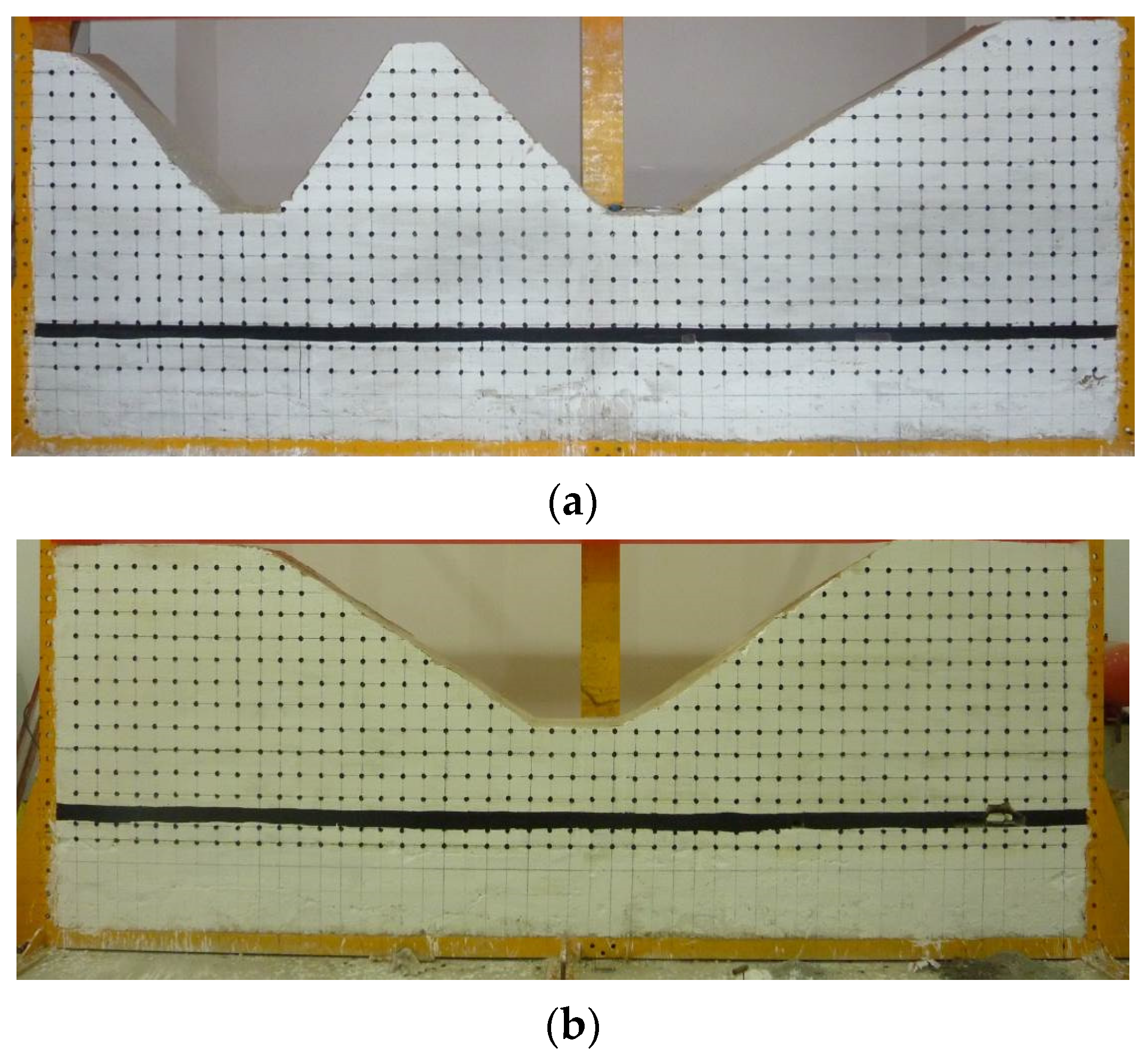
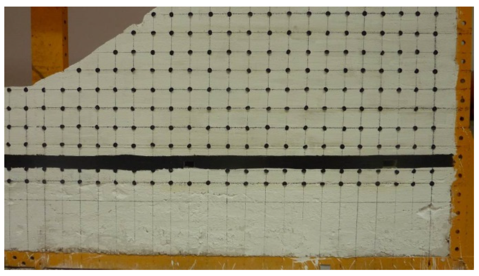
According to the mining geological conditions of the 20,109 working face, two sets of physically similar material simulation tests were carried out: the first model was completed on 20 January 2018, simulating the north–south strike section, studying the roadway layout and coal pillar stability; the second model was completed on 23 March, where the east–west section was simulated. The laws of mining pressure of mining towards the gully or away from the gully were studied. The model size (length × width × height) was 5000 mm × 300 mm × 1700 mm, and the scale of the geometric model was 1:200; model materials are detailed in Table 1. After the model was dried to meet the test strength requirements, the mining test was carried out, and corresponding observations and records were performed.
The model used sand as the aggregate, with gypsum and calcium carbonate as the bonding materials. According to the on-hole drilling histogram and the physical and mechanical parameters of the coal rock measured in the laboratory, the proportions of ingredients were determined, and the proportion of the materials required for laying each rock (coal) layer was calculated.
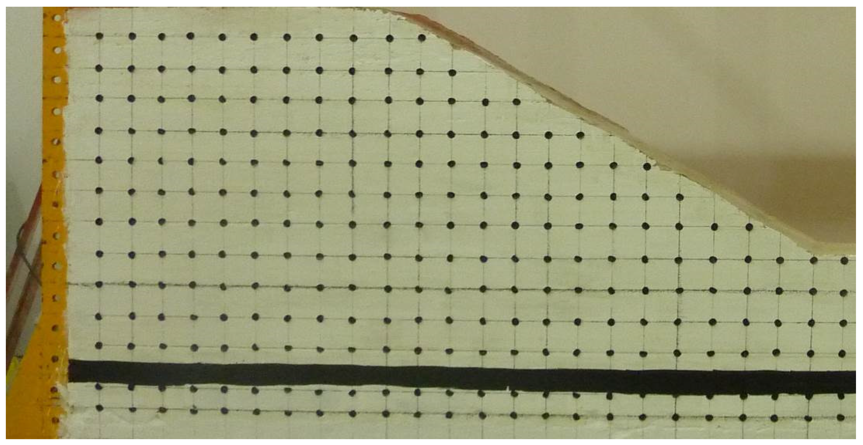
When the model was made, the materials required for the preparation of the coal seam were weighed, stirred with water to a suitable degree, layered, and vibrated; then, mica powder was used to simulate the contact surface of the rock layer. After the model was completed, it was cured for 15 to 20 days. After the model reached the required strength for the test, the front surface of the model was painted white, and a black ink bullet line was drawn with a grid of 10 cm × 10 cm to facilitate observations of the deformation of the model rock mass and destruction characteristics. The experimental model is shown in Figure 3.
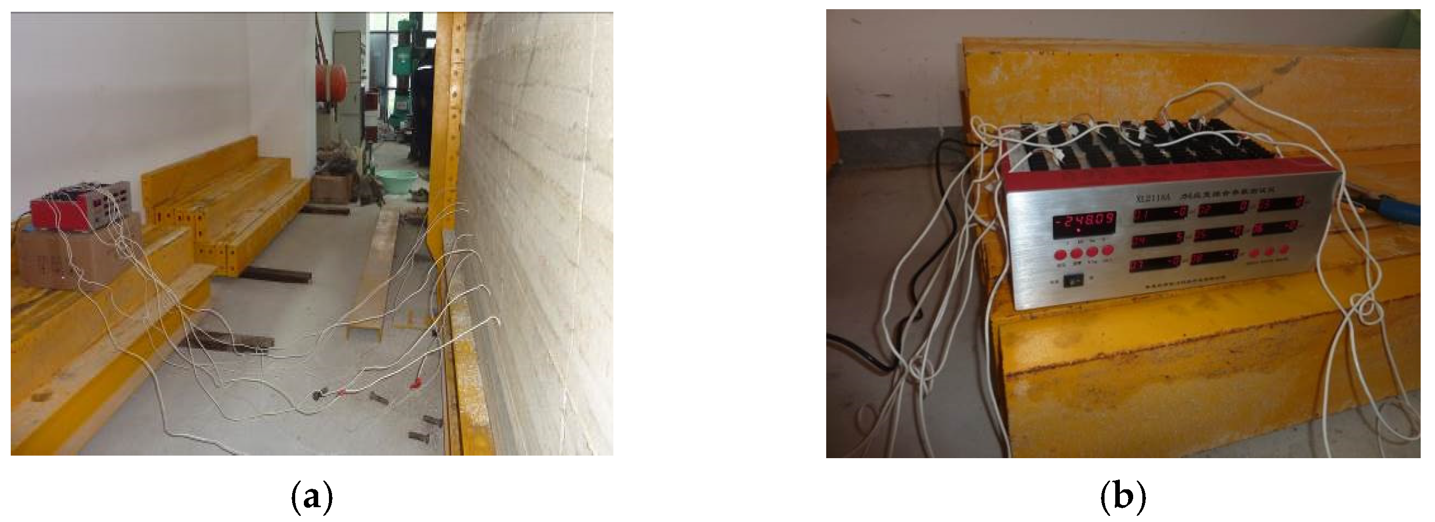
In order to analyze the variation law of vertical stress (advanced abutment pressure), vertical displacement, and horizontal displacement of roof overburdening during the mining of the working face, a pressure sensor was embedded in the model. The measuring point arrangement and instruments are shown in Figure 4.

4. Failure Characteristics of the Surrounding Rock of the Roadway under Different Positions

4.1. The Roadway Located below the Top of the Slope

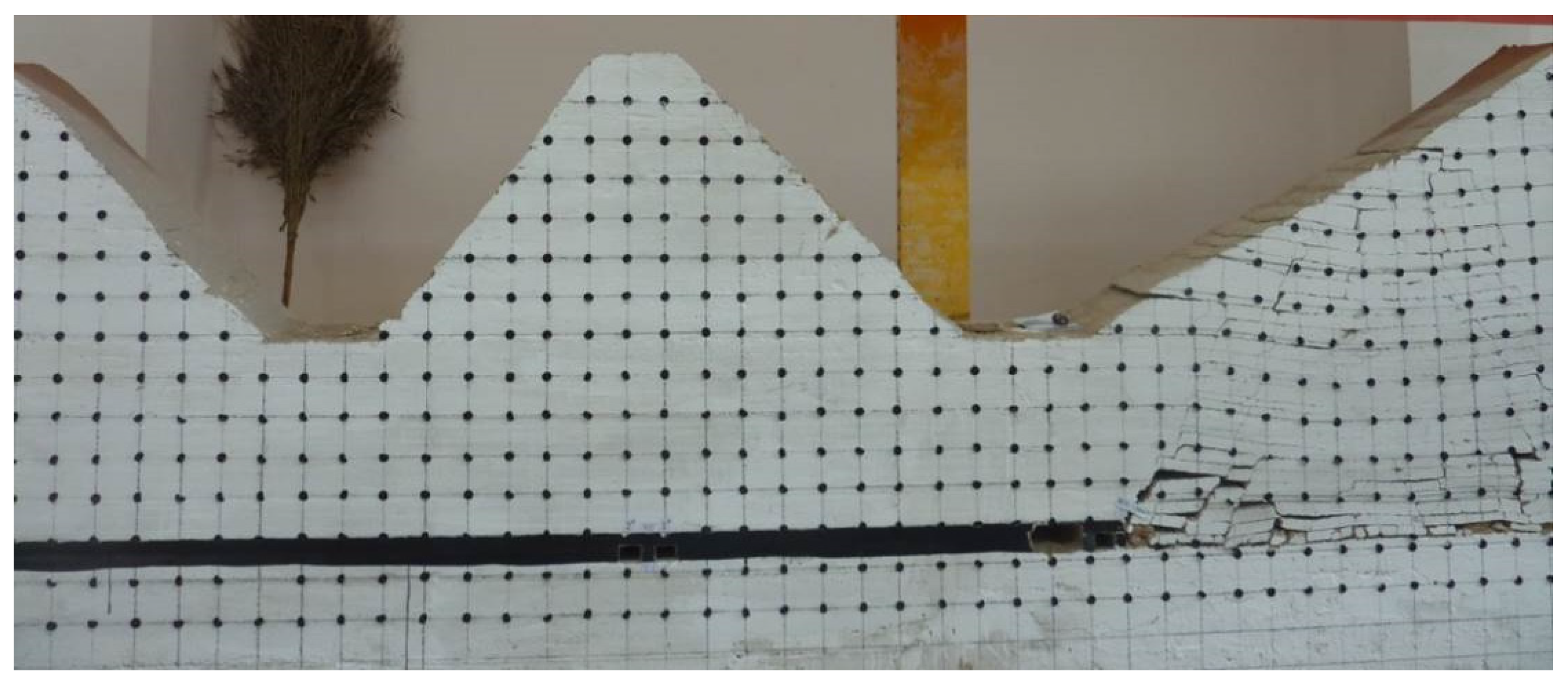
When the roadway was located below the top of the slope, it was analyzed according to the geological mechanics surface structure formation principle. The area was affected by horizontal tectonic stress, and it was more difficult to support both sides of the roadway along the mountain range and below the top of the slope. After successfully finishing the mining, the horizontal tectonic stress was relieved, and a crack above the roadway developed on both sides, which led to an increase in the bearing capacity of the coal pillars and increased stress concentration, as shown in Figure 5 and Figure 6.
After completing the work, the main roof above the working face collapsed and tended to be stable. Cracks developed from the bottom to the top on both sides, the surface exhibited tensile fracture, and the rock layer above the roadway was “diamond shaped”. Deformation and failure occurred at both sides of the actual mining roadway affected by mining stress. At this time, the pressure of coal pillars on both sides of the roadway increased.

4.2. The Roadway Located below the Slope Surface

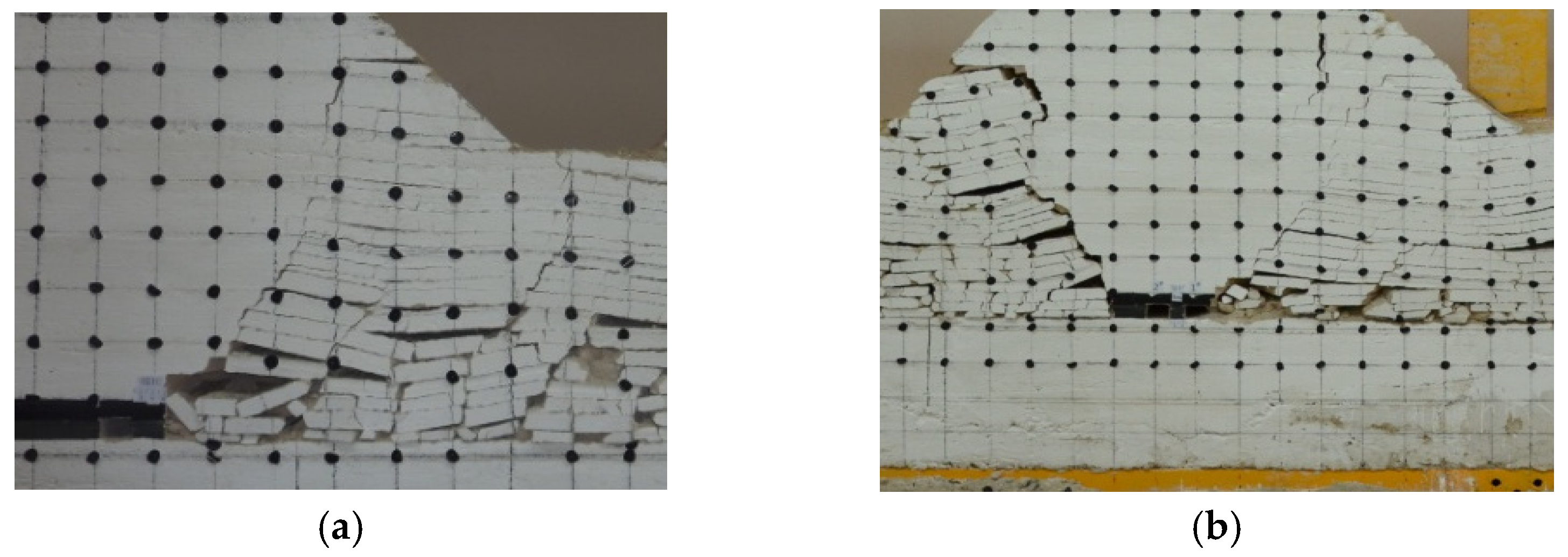
When the roadway was located below the slope surface, the roadway was less affected by the horizontal structure. Due to the asymmetry of the overburden structure above it, the overburden rock near the slope bottom of the roadway was damaged by tensile fracture after finishing the mining work, and maintaining the roof support will be more difficult, as can be seen from Figure 7 and Figure 8.
After finishing mining, collapse fissures of the overlying strata developed from bottom to top and to the side of the slope bottom, and the surface exhibited tensile fracture. The roadway below the slope surface showed obvious asymmetric deformation and damage, both sides of the top of the roadway were particularly obvious, and the stability of the two sides was relatively good.

4.3. The Roadway Located below the Bottom of Slope

When the gateway was located below the surface of the slope, according to the formation principle of geomechanical surface structures, the two sides of the roadway section along the direction of the valley and near the bottom of the valley were in a tension state, affected by the horizontal tectonic stress. The overburden weight above was smaller, and excavation of the gateway was relatively easy. Overburdening rock above the roadway maintained good stability after stoping in the working face, as shown in Figure 9 and Figure 10.
After finishing the simulation, the overburden fractures were developed from the bottom to the top of the slope, and the strata above the roadway was presented in the form of an “inverted triangle”. Due to the support of the fallen strata on both sides, the surrounding rock of the actual mining roadway bore less stress, and the surrounding rock could maintain stability.

5. Laws of Ground Behavior in Different Directions of Working

(1)
Mining towards the gully.
The laws of ground behavior appeared to be different for the different directions of working. First, mining towards the gully was carried out; according to the simulation calculation theory, each excavation was 5 cm, i.e., the actual distance was 10 m.
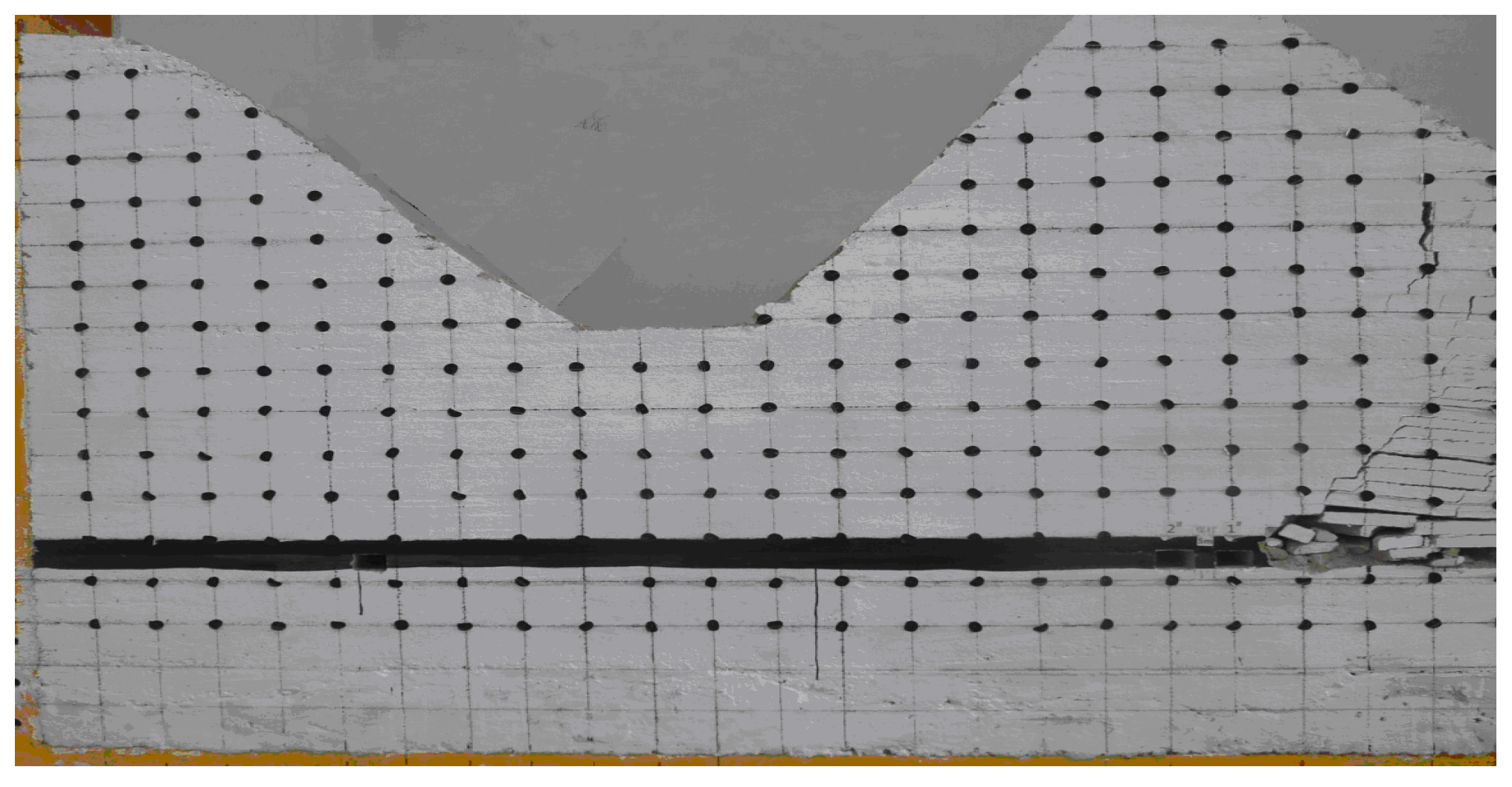
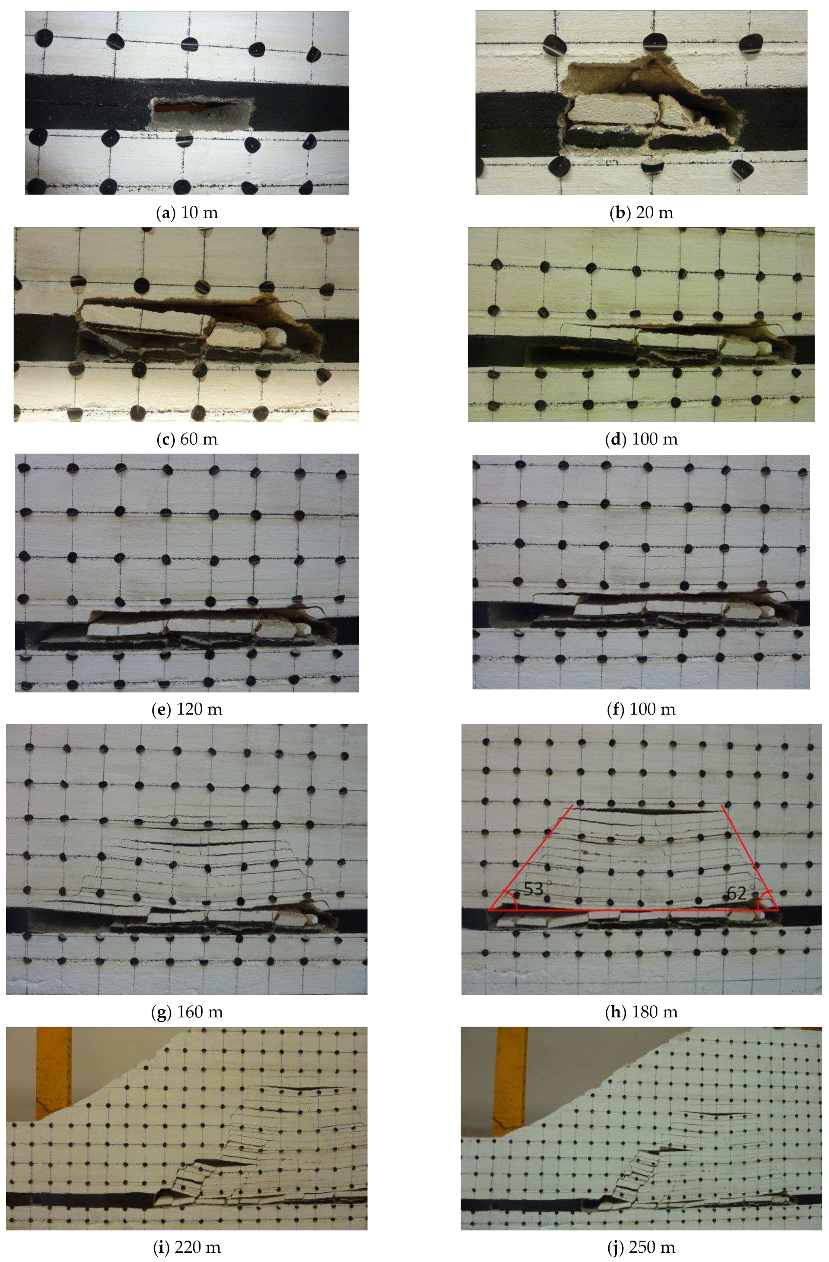
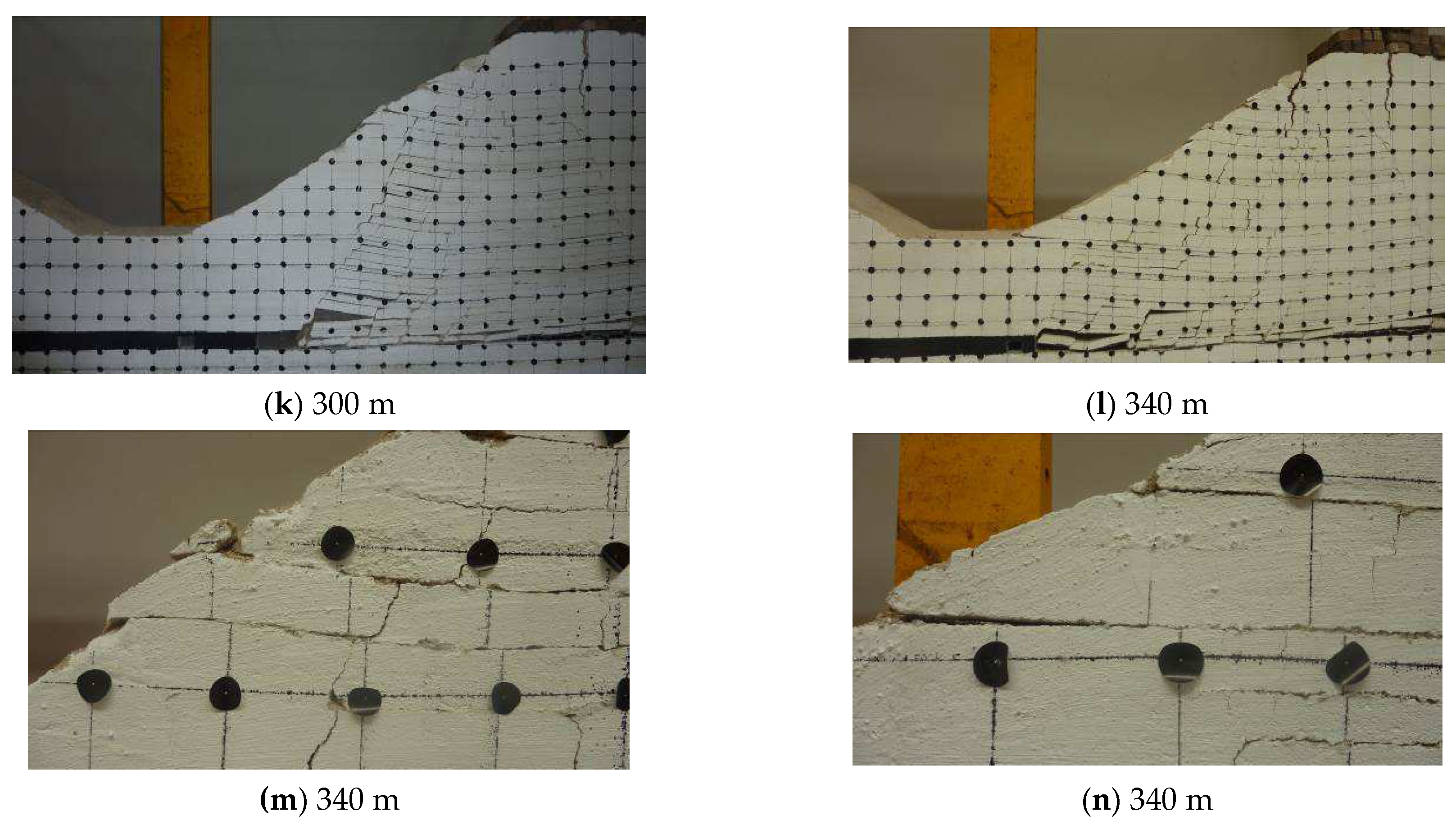
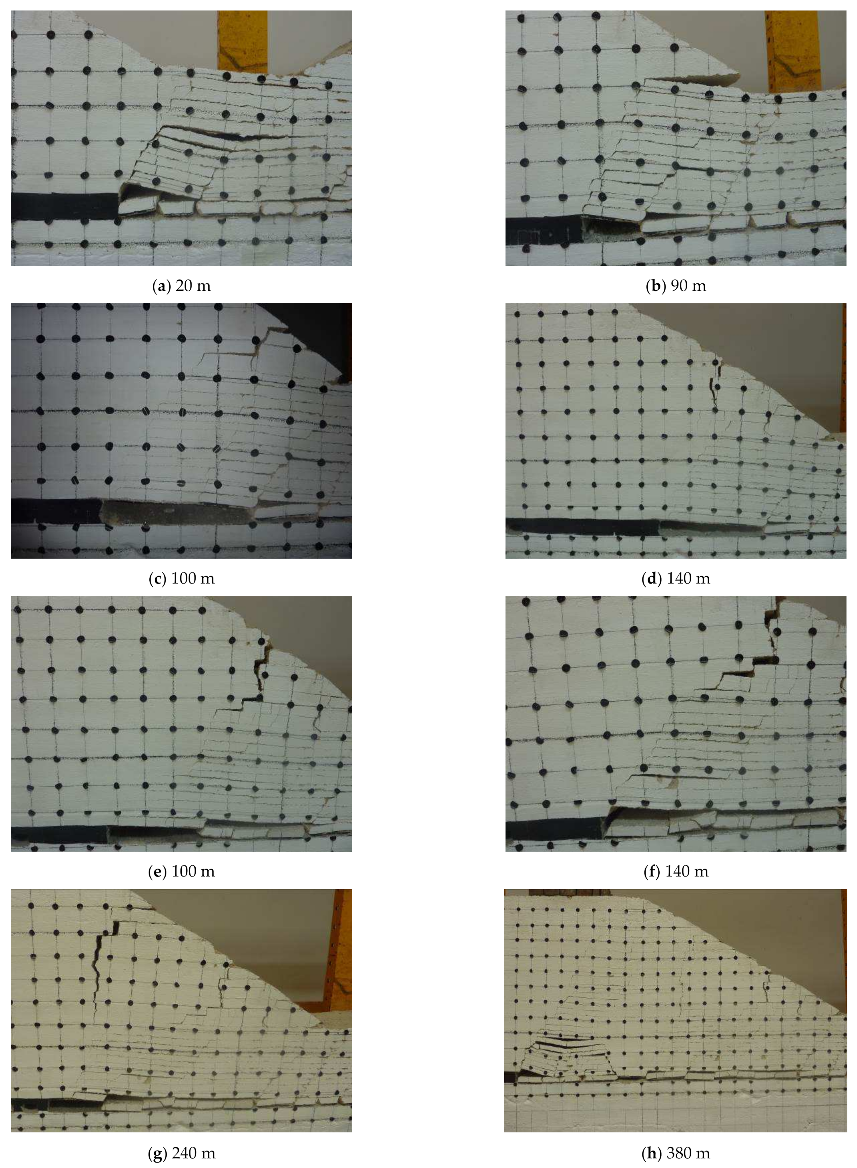
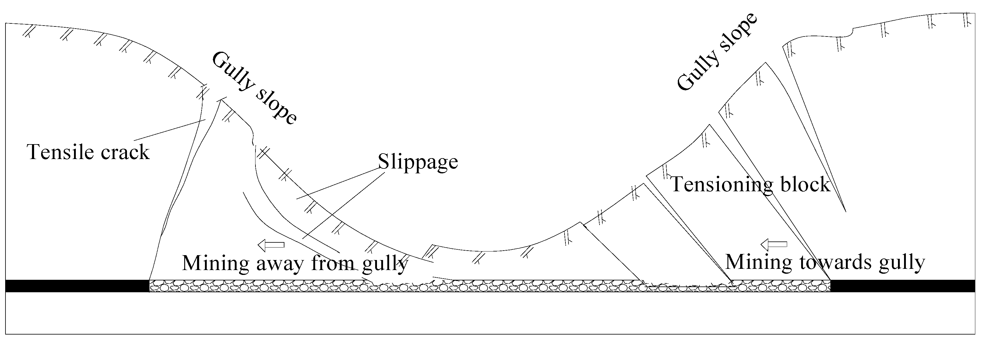
When the working face stoped to the bottom of the slope body, the height of the overlying rock gradually decreased, and the movement and collapse laws of overburden were different from those of the conventional surface. When the working face advanced to 300 m, as shown in Figure 11 and Figure 12, a tensile crack was formed near the top of the slope, and the tensile crack developed downward with mining of the working face. When the working face advanced to 340 m, as shown in Figure 12l, longitudinal fissures formed due to overburden collapse, and surface tension cracks ran through and converged. During the mining at this stage, the slope surface exhibited subsidence towards the bottom of the gully, and slips occurred at the interface of different strata, as shown in Figure 12m,n.
From the above tests, the following characteristics of the overburden movement were determined:
  • The right side of the slope was goaf; therefore, the restriction degree of the slope body decreased, especially in the right horizontal direction, which led to a tendency of the overlying strata sliding to the bottom right of the gully, in addition to downward displacement in the process of stoping. Therefore, when the pulling force towards the right reached a certain degree, a relatively obvious tensile crack was generated at the top of the slope, and the crack developed downward along with working face mining, and finally, the surface tension cracks connected with longitudinal fissures formed by overburden collapse, causing overlying strata with weakened constraints to slip towards the bottom of the gully.
  • Due to the influence of actual mining, the shear strength of the weak surface of overburden gradually became smaller. The slope of the gully was near the goaf; therefore, resistance to additional horizontal stress overburden depended only on the friction between the layers. When the additional horizontal stress was greater than the shear resistance between strata, the strata of the slope body would slip horizontally towards the bottom of the gully to release the additional horizontal stress caused by actual mining.
  • Laws of advanced abutment pressure and displacement of slope
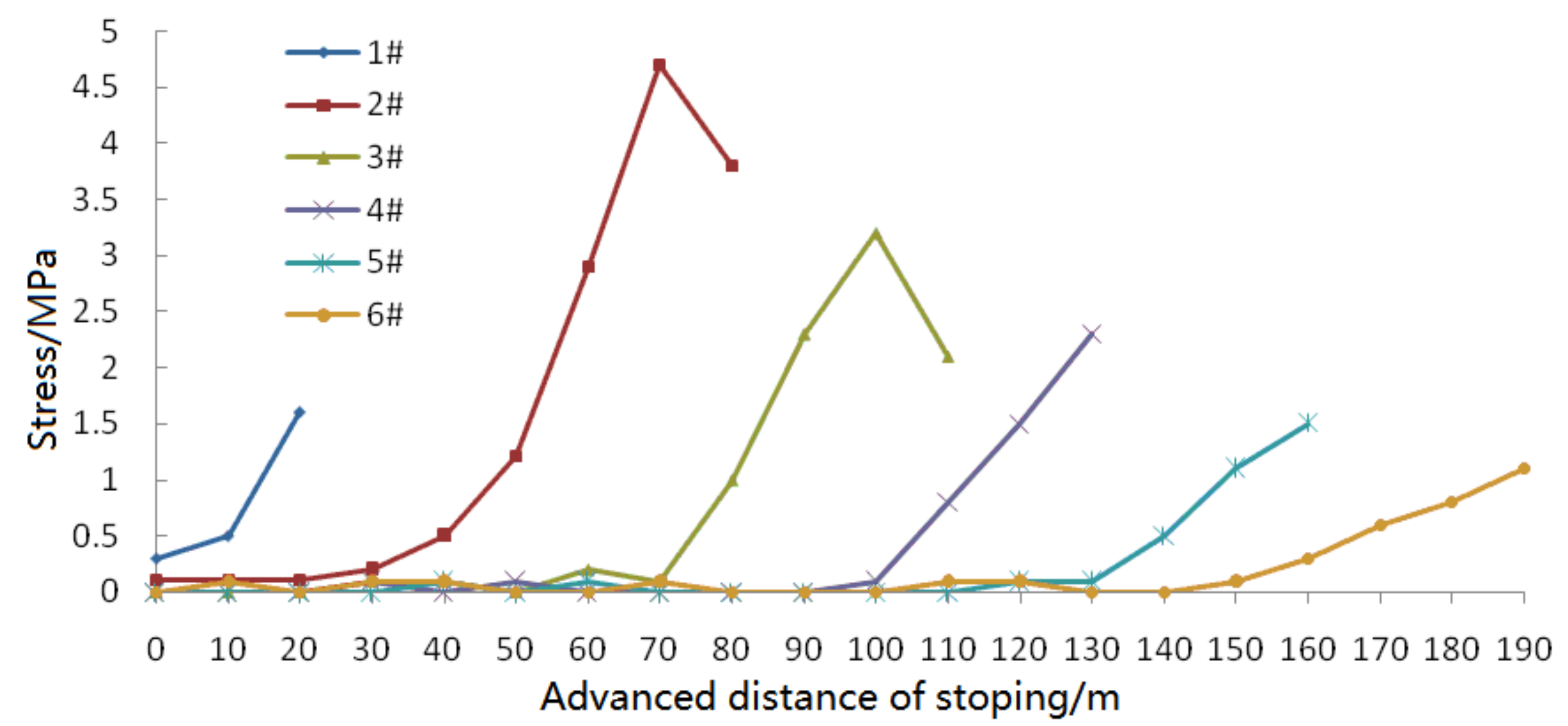
Figure 13 shows the advanced abutment pressure variation in the roof of the working face. It can be seen from the curve on the graph that variations in the 1# and 2# pressure sensors buried in the non-slope section are similar to those of the conventional surface shallow coal seam. It exhibits obvious periodicity, and the influence range of advance abutment pressure is 45 m. The maximum stress concentration factor of the advance abutment pressure is approximately 2.1.
The 3#, 4#, 5#, and 6# pressure sensors were located in the downhill section. It can be seen from the sensor pressure curve that the distribution law of advance abutment pressure during the mining of working face is different from that of the conventional surface working face. The specific performance indicates that the influence range of advance abutment pressure increased, and the concentration factor of advance abutment pressure decreased gradually, from 1.8 to 1.3, and nearly to 1.0 when approaching the bottom of the gully, but the roof could easily be cut off directly, causing dynamic pressure damage. After the occurrence of tensile cracks on the top of slope, the overlying strata lost the tension restraint on the left side due to the tensile cracks, and the slope had a tendency of turning over towards the bottom of the gully until the longitudinal fissures formed by overburden collapse and surface tension cracks ran through and converged.
(2)
Mining away from the gully.
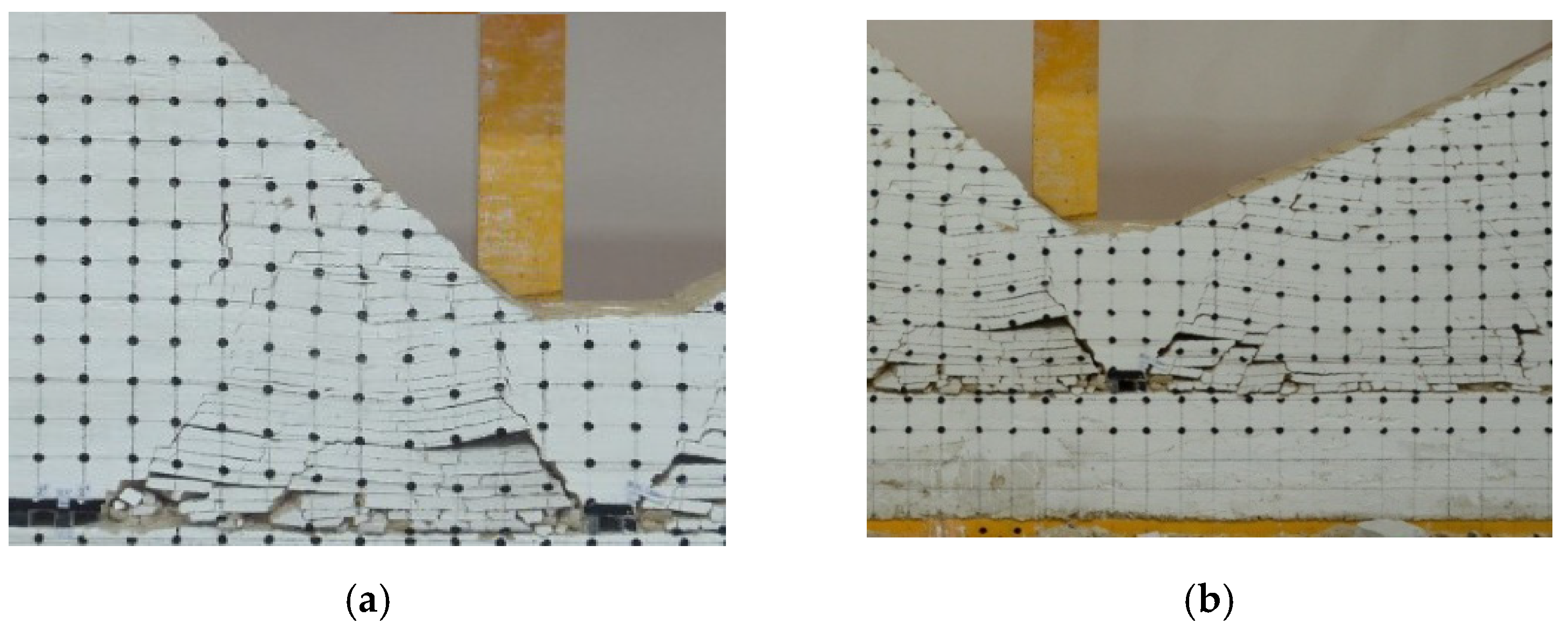
Figure 14 and Figure 15 show the response to mining away from the gully. The characteristics of the overlying strata were obviously different from those of mining towards the gully. It can be seen from the graph that with actual mining of the working face, the basic roof did not produce separation and stratified collapse, as in mining towards the gully; instead, almost-vertical tensile cracks were created directly. The cracks developed from the surface of the slope to the coal wall of the working face. The rock cut by the tensile crack turned over to the goaf and formed a multi-block articulated structure at the coal wall, but the articulated structure was unstable and temporary. With the actual mining of the working face, the articulated structure slid and lost stability, inducing dynamic pressure.
With the gradual increase in collapsed rock mass, due to the swelling property of broken rock blocks, the width of the tensile crack became smaller and smaller. With the bending and subsidence of the unfractured overburden on the right side, the fault blocks slowly came into contact with the complete overburden, forming an occlusion zone, which restricted the formation of tensile cracks to a certain extent. It can be seen from Figure 15h that the working face entered the non-slope section; at this point, no tensile cracks were generated, and the movement and collapse characteristics of overburden rock were similar to those of conventional surface coal seam mining.
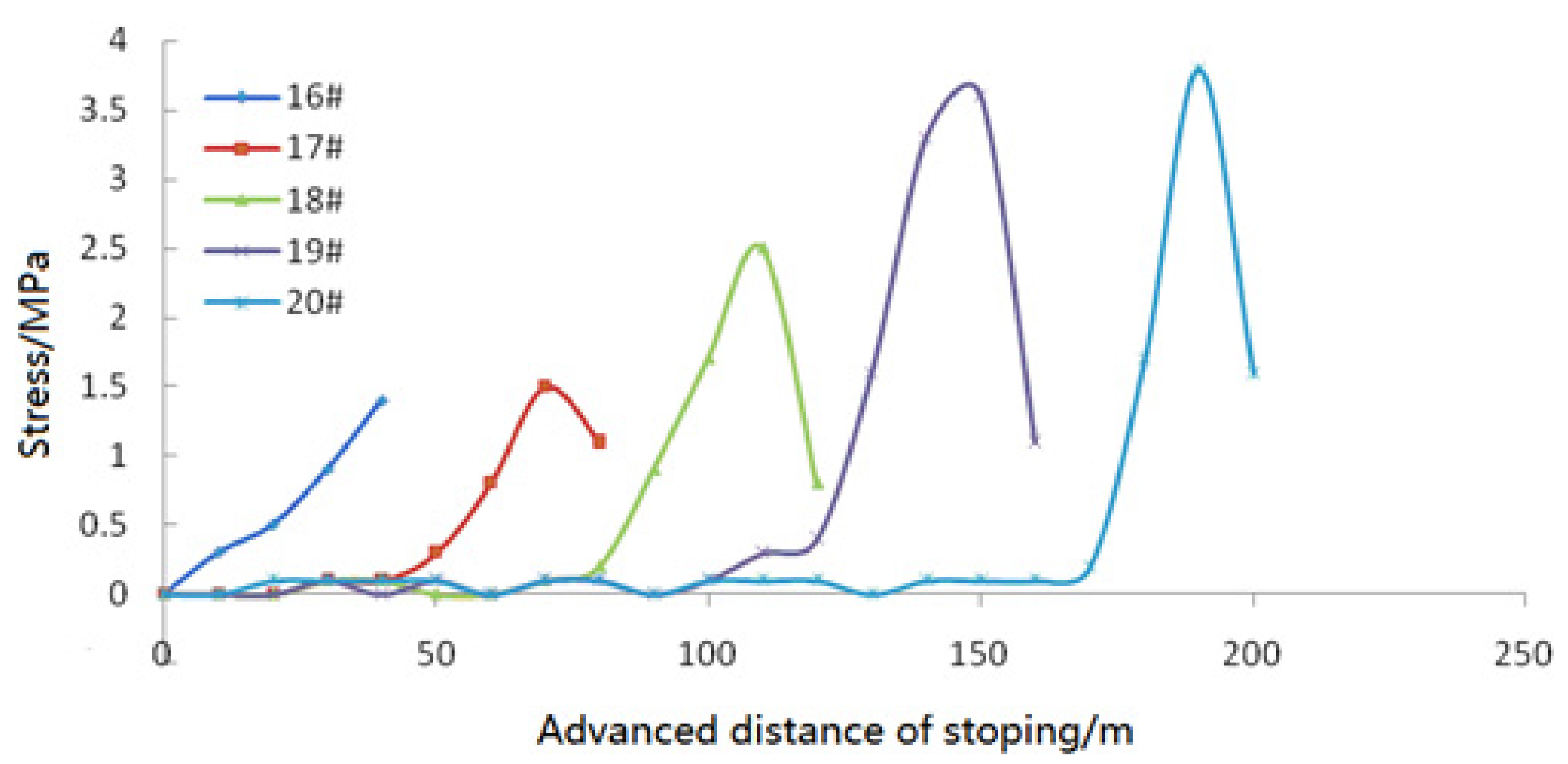
It can be seen from the curve in Figure 16 that the advance abutment pressure increased with the increase in the length of the cantilever until the formation of the tensile cracks reached the maximum; then, the advance abutment pressure rapidly decreased after the multi-block articulated structure was turned over to the bottom of the gully. As the working surface continued to advance, the new cantilever was formed, the advance abutment pressure was gradually increased, it reached the maximum before the formation of the next tensile cracks, and then it rapidly reduced after the collapse and reversal of the multi-block. Due to the increase in the overburden height, the geometric volume of the fracture blocks increased, as did the peak value of the advance abutment pressure. However, due to the reduction in horizontal dimensions of the multi-block, the periodical weight interval distance and duration decreased, i.e., when mining away from the gully, the roof behavior appeared intense, the peak value grew larger and larger, and the duration was shorter and shorter.

6. Comprehensive Analysis of Test Results

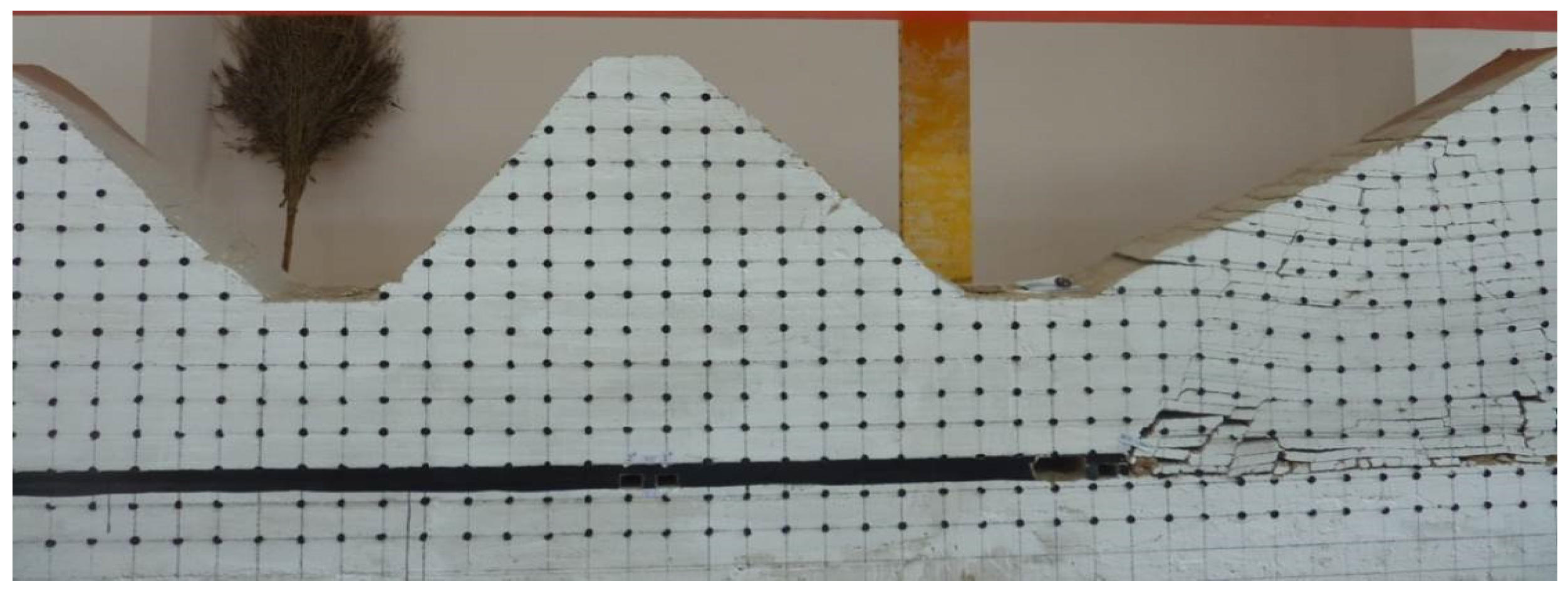
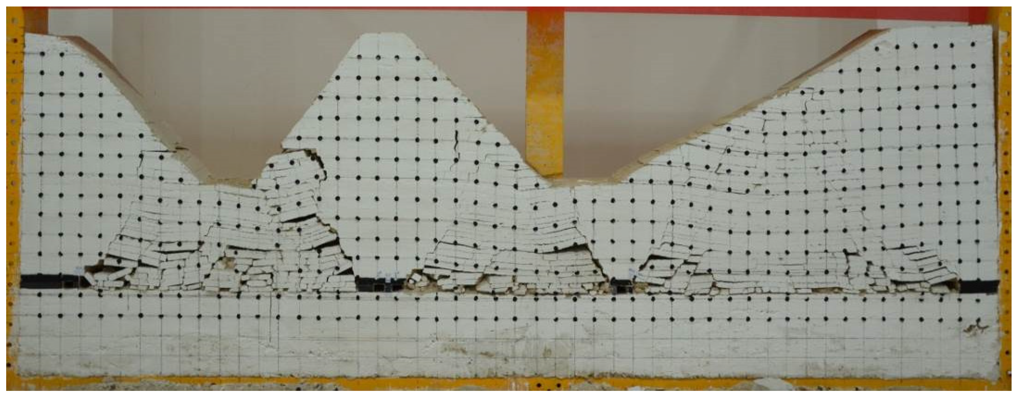
From Figure 17, it can be seen that when the actual mining roadway was located in different positions with different geomorphological features, the stability of the surrounding rock and the degree of disturbance damage were different:
  • When the roadway was located below the top of the slope, the two sides of the roadway were vulnerable to compression damage during excavation; after mining, the deformation of rock surrounding the roadway was aggravated by mining stress, and the abutment pressure of the coal body on the two sides of the roadway increased;
  • When the roadway was located below the bottom of the gully, the stability of rock surrounding the roadway was good during the excavation; after mining, the roadway was less affected by mining and could remain stable;
  • When the roadway was located below the slope surface, the failure of surrounding rock exhibited significant asymmetry under the influence of mining stress.
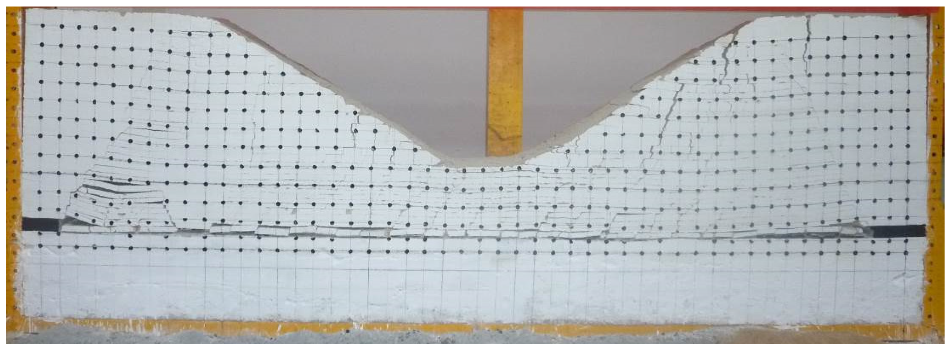
The model 2 test reflected the difference between mining towards or away from gully, as shown in Figure 18 and Figure 19.
  • When mining towards the gully, the ground behavior of the working face was different from that of the conventional surface mining section. The concrete manifestation showed that the ground behavior was gentle, the interval distance periodical weight was longer, and the advance abutment pressure was small, i.e., the concentration factor of the advance abutment pressure was small.
  • When mining away from the gully, the ground behavior laws were very different from those of mining towards the gully; the ground behavior appeared intense. With the increase in overburden thickness, the interval distance periodical weight became shorter and shorter, and the roof behavior appeared intense. Dynamic pressure was easily induced, with a high concentration factor of advance abutment pressure.

7. Conclusions

  • When a roadway is located below the top of the slope, the deformation of rock surrounding the roadway is aggravated by mining stress; when a roadway is located below the bottom of a gully, it is less affected by mining and could remain stable. Therefore, the actual mining roadway should be situated in the area below the bottom of the gully as much as possible.
  • The ground behavior laws of the working face in the gully geomorphology area are related to the position of the working face and the direction of working. When mining towards a gully, the ground behavior is gentle, the interval distance periodical weight is longer, and the surface slips towards the gully; when mining away from a gully, the ground behavior appears intense, and the pressure is sudden and short with an increase in overburden thickness and decrease in interval distance periodical weight.
  • When the working face passes through a gully, dumping of the hydraulic support should be prevented in sections with mining towards the gully; in sections of mining away from a gully, the supports should be strengthened to prevent the support and other equipment from being crushed.
  • In actual mining, mining towards the gully should be adopted as much as possible in the stoping of the working face. In this way, the ground behavior is gentle, the interval distance periodical weight is longer, and the advance abutment pressure is small.

Author Contributions

Data curation, S.M.; Funding acquisition, Y.K.; Methodology, S.M.; Writing—original draft, S.M.; Writing—review & editing, Y.K. All authors have read and agreed to the published version of the manuscript.

Funding

This research was funded by the projects “Development of all-weather displacement monitoring device under complex terrain conditions” (2021YBXM31) and “Research on general survey and control technology and equipment of coal mine disaster causing factors” (2018-JIZHUANGSI-ANQUANSHENGCHANYANJIU-01).

Institutional Review Board Statement

Not applicable.

Informed Consent Statement

Not applicable.

Data Availability Statement

The data used to support the findings of this study are available from the corresponding author upon request.

Conflicts of Interest

The authors declare that they have no conflict of interest.

References

  1. Zhang, D.S.; Fan, G.W.; Wang, X.F. Characteristics and stability of slope movement response to underground mining of shallow coal seams away from gullies. Int. J. Min. Sci. Technol. 2012, 22, 47–50. [Google Scholar] [CrossRef]
  2. Zhang, Z.Q.; Xu, J.L.; Zhu, W.B.; Zhenjun, S. Simulation research on the influence of eroded primary key strata on dynamic strata pressure of shallow coal seams in gully terrain. Int. J. Min. Sci. Technol. 2012, 22, 51–55. [Google Scholar] [CrossRef]
  3. Si, G.; Jamnikar, S.; Lazar, J.; Shi, J.Q.; Durucan, S.; Korre, A.; Zavšek, S. Monitoring and modelling of gas dynamics in multi-level longwall top coal caving of ultra-thick coal seams, part I: Borehole measurements and a conceptual model for gas emission zones. Int. J. Coal Geol. 2015, 144, 98–110. [Google Scholar] [CrossRef]
  4. Xie, Y.S.; Zhao, Y.S. Numerical simulation of the top coal caving process using the discrete element method. Int. J. Rock Mech. Min. Sci. 2009, 46, 983–991. [Google Scholar] [CrossRef]
  5. Vakili, A.; Hebblewhite, B.K. A new cavability assessment criterion for Longwall Top Coal Caving. Int. J. Rock Mech. Min. Sci. 2010, 47, 1317–1329. [Google Scholar] [CrossRef]
  6. Wang, J.C.; Yang, S.L.; Li, Y.; Wei, L.K.; Liu, H.H. Caving mechanisms of loose top-coal in longwall top-coal caving mining method. Int. J. Rock Mech. Min. Sci. 2014, 71, 160–170. [Google Scholar] [CrossRef]
  7. Wang, J.C.; Zhang, J.W.; Li, Z.L. A new research system for caving mechanism analysis and its application to sublevel top-coal caving mining. Int. J. Rock Mech. Min. Sci. 2016, 88, 273–285. [Google Scholar] [CrossRef]
  8. Xie, G.X.; Chang, J.C.; Yang, K. Investigation on displacement field characteristics of tunnels surrounding rock and coal seam at FMTC face. J. Coal Sci. Eng. 2006, 12, 1–5. [Google Scholar]
  9. Xie, G.X.; Chang, J.C.; Yang, K. Investigations into stress shell characteristics of surrounding rock in fully mechanized top-coal caving face. Int. J. Rock Mech. Min. Sci. 2009, 46, 172–181. [Google Scholar] [CrossRef]
  10. Li, L.; Liu, Z.G.; Chen, P.P.; Liu, G. Study on fully-mechanized top coal caving mining under water body with shallow overburden and thin bedrock. Adv. Mater. Res. 2013, 734–737, 644–649. [Google Scholar] [CrossRef]
  11. Zhu, Y.J.; Peng, G. Similar material simulation research on movement law of roof over-lying strata in stope of fully mechanized caving face with large mining height. J. Coal Sci. Eng. 2010, 16, 6–10. [Google Scholar] [CrossRef]
  12. Liu, J.; Chen, S.L.; Wang, H.J.; Li, Y.C.; Geng, X.W. The migration law of overlay rock and coal in deeply inclined coal seam with fully mechanized top coal caving. J. Environ. Biol. 2015, 36, 821–827. [Google Scholar]
  13. Alehossein, H.; Poulsen, B.A. Stress analysis of longwall top coal caving. Int. J. Rock Mech. Min. Sci. 2010, 47, 30–41. [Google Scholar] [CrossRef]
  14. Shen, J.; Meng, D.; Wei, L. Study on the structural system of roof in fully mechanized top coal caving. Appl. Mech. Mater. 2011, 90–93, 2041–2044. [Google Scholar] [CrossRef] [Green Version]
  15. He, F.L.; Wang, X.M.; Zhang, D.Q.; He, S.S. Study on parameters of support for control of roof fall and rib spalling in large fully mechanized top coal caving end face. Adv. Mater. Res. 2013, 616–618, 421–425. [Google Scholar] [CrossRef]
  16. Du, F.; Bai, H.B. Mechanical model for immediate roof structure of thin bedrock in fully-mechanized sublevel caving face. Electron. J. Geotech. Eng. 2012, 17, 3075–3088. [Google Scholar]
  17. Yin, G.; Li, X.; Guo, W. Photo-eiastic experimental and field measurement study of ground pressure of surrounding rock of large dip angle working coal face. Chin. J. Rock Mech. Eng. 2010, 29, 3336–3343. [Google Scholar]
  18. Zhang, J.; Xu, G.; Ma, M.; Wang, H.; Qi, F. Strata behavior law at fully mechanized caving face in thick coal seam with large dip angle Safety in Coal Mines. Saf. Coal Mines 2014, 45, 181–183. [Google Scholar]
  19. Wu, X.Z.; Jiang, Y.J.; Guan, Z.C.; Wang, G. Estimating the support effect of the energy-absorbing rock bolt based on the mechanical work transfer ability. Int. J. Rock Mech. Min. Sci. 2018, 103, 168–178. [Google Scholar] [CrossRef] [Green Version]
  20. Gu, S.; Chen, P.; Wang, J.; Wang, H. Field measurement study of mine strata pressure behavior law of coal mining face under goaf. Coal Mine Eng. 2013, 9, 64–67. [Google Scholar]
  21. Lin, S.Z. A modelling research into slope deformation activities associated with underground mining. J. Xi’an Coll. Geol. 1989, 11, 70–79+112. [Google Scholar]
  22. Singh, V.K. Slope stability study for optimum design of an opencast project. J. Sci. Ind. Res. 2006, 65, 47–56. [Google Scholar]
  23. Sun, L.; Zhang, Y.; Wang, Y.; Liu, Q. Study on the Reoxidation Characteristics of Soaked and Air-Dried Coal. J. Energy Resour. Technol. 2019, 141, 022203. [Google Scholar] [CrossRef]
  24. Erginal, A.E.; Türkeş, M.; Ertek, T.A. Geomorphological investigation of the excavation-induced Dundar landslide, Bursa, Turkey. Geogr. Ann. Ser. A Phys. Geogr. 2008, 90, 109–123. [Google Scholar] [CrossRef]
  25. Kang, J.R. Analysis of effect of fissures caused by underground mining on ground movement and deformation. Chin. J. Rock Mech. Eng. 2008, 27, 59–64. [Google Scholar]
  26. Singh, R.; Mandal, P.K.; Singh, A.K.; Kumar, R.; Maiti, J.; Ghosh, A.K. Upshot of strata movement during underground mining of a thick coal seam below hilly terrain. Int. J. Rock Mech. Min. Sci. 2008, 45, 29–46. [Google Scholar] [CrossRef]
  27. Fan, K.G.; Liu, G.L.; Xiao, T.Q. Study on overlying strata movement and structure features aroused by mountainous shallow buried coal seam mining. In Proceedings of the 2nd International Conference on Mine Hazards Prevention and Control, Qingdao, China, 15–17 October 2010; Volume 12, pp. 76–82. [Google Scholar]
  28. Yuan, T. Research on Mining Subsidence Laws in Shaanxi Loess Gully Region. Master’s Thesis, Xi’an University of Science and Technology, Xi’an, China, 2011. [Google Scholar]
  29. Ji, H.; Yu, X.Y. Analysis and study on formation mechanism of subsidence disaster in gully region of shallow depth seam. Coal Eng. 2012, 6, 69–71. [Google Scholar]
  30. Li, W.X.; Mei, S.H.; Zai, S.H.; Zhao, S.; Liang, X. Fuzzy models for analysis of rock mass displacements due to underground mining in mountainous areas. Int. J. Rock Mech. Min. Sci. 2006, 43, 503–511. [Google Scholar] [CrossRef]
  31. He, M.C.; Feng, J.L.; Sun, X.M. Stability evaluation and optimal excavated design of rock slope at Antaibao open pit coal mine, China. Int. J. Rock Mech. Min. Sci. 2008, 45, 289–302. [Google Scholar] [CrossRef]
  32. Yu, L.; Ignatov, Y.; Ivannikov, A.; Khotchenkov, E.; Krasnoshtanov, D. Common features in the manifestation of natural and induced geodynamic events in the eastern regions of Russia and China. IOP Conf. Ser. Earth Environ. Sci. 2019, 324, 012004. [Google Scholar] [CrossRef]
  33. Rybak, J.; Khayrutdinov, M.M.; Kuziev, D.A.; Kongar-Syuryun, C.B.; Babyr, N.V. Prediction of the geomechanical state of the rock mass when mining salt deposits with stowing. J. Min. Inst. 2022, 253, 61–70. [Google Scholar] [CrossRef]
  34. Khayrutdinov, A.M.; Kongar-Syuryun, C.B.; Kowalik, T.; Tyulyaeva, Y.S. Stress-strain behavior control in rock mass using different-stregth backfill. Min. Inf. Anal. Bull. 2020, 2020, 42–55. [Google Scholar] [CrossRef]
  35. Rybak, J.; Gorbatyuk, S.M.; Kongar-Syuryun, C.B.; Khairutdinov, A.M.; Tyulyaeva, Y.S.; Makarov, P.S. Utilization of Mineral Waste: A Method for Expanding the Mineral Resource Base of a Mining and Smelting Company. Metallurgist 2021, 64, 851–861. [Google Scholar] [CrossRef]
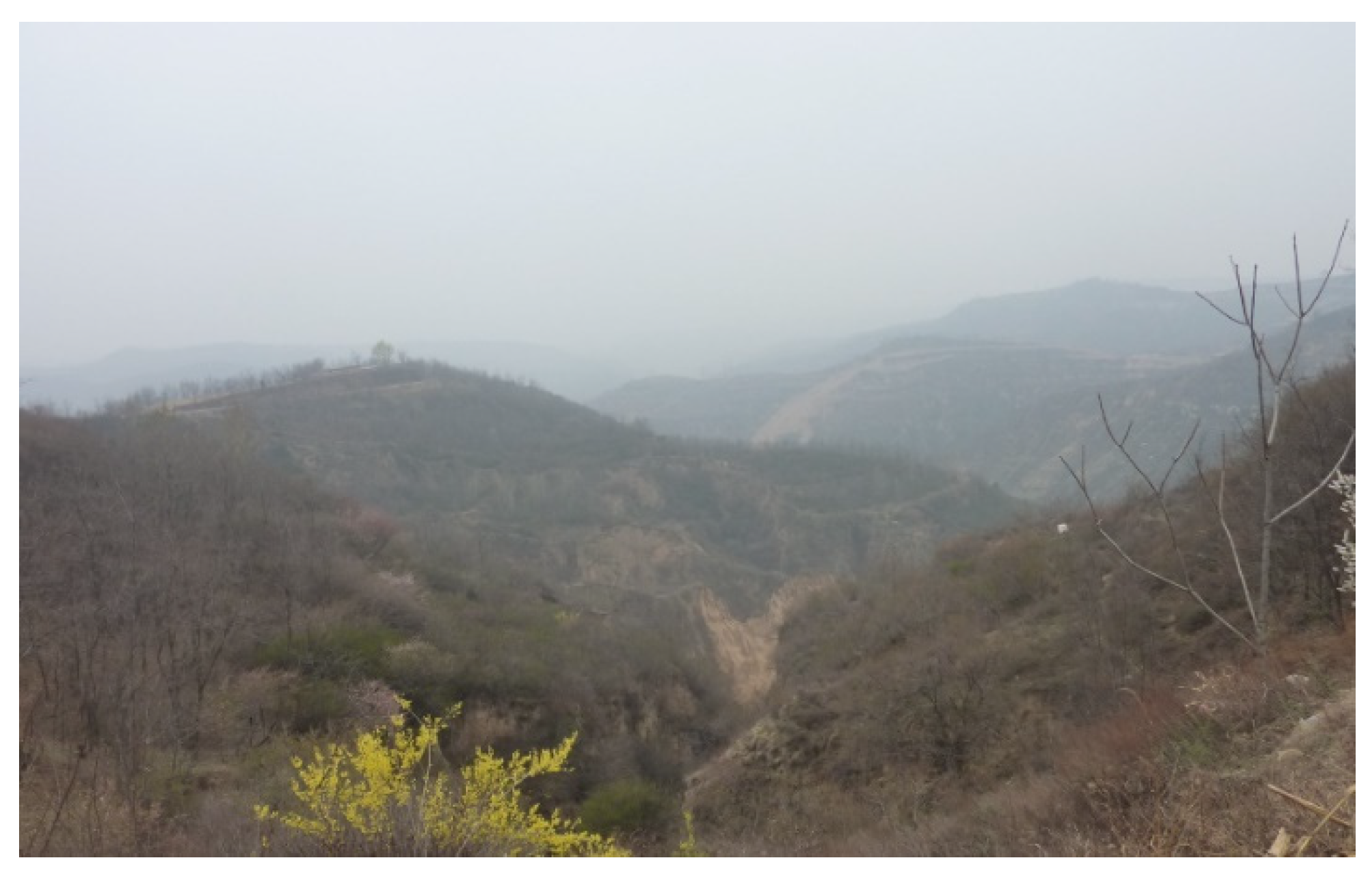
Figure 1. A typical gully landform.
Sustainability 14 13941 g001
Figure 2. Layout plan of the working face.
Sustainability 14 13941 g002
Figure 3. Original appearance of the test model. (a) Model 1. (b) Model 2.
Sustainability 14 13941 g003
Figure 4. Test systems of two models. (a) Embedded pressure sensor. (b) Static resistance strain gauge.
Sustainability 14 13941 g004
Figure 5. Roadway located below the top of the slope.
Sustainability 14 13941 g005
Figure 6. Overburden damage of roadway. (a) Cracks develop to the surface. (b) Roadway damaged by extrusion.
Sustainability 14 13941 g006
Figure 7. Roadway located below the slope surface.
Sustainability 14 13941 g007
Figure 8. Overburden damage of the roadway. (a) Overburden rock collapse. (b) Asymmetric damage.
Sustainability 14 13941 g008
Figure 9. Roadway located below the bottom of slope.
Sustainability 14 13941 g009
Figure 10. Overburden damage of the roadway. (a) Slope damage. (b) Roadway roof sinking damage.
Sustainability 14 13941 g010
Figure 11. Schematic diagram of mining towards the gully.
Sustainability 14 13941 g011
Figure 12. Stages of mining towards the gully.
Sustainability 14 13941 g012aSustainability 14 13941 g012b
Figure 13. Vertical stress curves of measuring points.
Sustainability 14 13941 g013
Figure 14. Schematic diagram of the back groove section.
Sustainability 14 13941 g014
Figure 15. Stages of mining away from the gully.
Sustainability 14 13941 g015
Figure 16. Vertical stress curves of measuring points.
Sustainability 14 13941 g016
Figure 17. Overview of the model after excavation.
Sustainability 14 13941 g017
Figure 18. Overview after the excavation of model two.
Sustainability 14 13941 g018
Figure 19. Schematic diagram of overburden failure in coal seam mining under a gully slope.
Sustainability 14 13941 g019
Table 1. Proportioning table of simulation materials.
Thickness/mRock LayerLayer Thickness (m)SandCarbonate (kg)Gypsum (kg)
7Medium sandstone2.0012.800.962.24
1.509.600.721.68
5Mudstone2.5016.661.661.66
12Sandy mudstone2.5017.140.862.00
2.0013.710.681.60
2.0013.710.681.60
2.0013.710.681.60
7Mudstone2.0013.331.331.33
6Fine sandstone2.0012.002.002.00
2.0012.002.002.00
2.0012.002.002.00
4Mudstone2.0013.331.331.33
6.3Coal2.0013.710.681.60
1.5010.280.521.20
4Medium sandstone2.0012.800.962.24
15Mudstone2.5016.661.661.66
2.5016.661.661.66
2.5016.661.661.66
18Sandy mudstone3.0020.571.282.40
2.0013.710.681.60
2.0013.710.681.60
Publisher’s Note: MDPI stays neutral with regard to jurisdictional claims in published maps and institutional affiliations.