Article

A Conceptual Design and Analysis of a Novel Trigeneration System Consisting of a Gas Turbine Power Cycle with Intercooling, Ammonia–Water Absorption Refrigeration, and Hot Water Production

by
Ayşe Fidan Altun
Mechanical Engineering Department, Engineering Faculty, Bursa Uludag University, Bursa 16059, Türkiye
Sustainability 2022, 14(19), 11820; https://doi.org/10.3390/su141911820
Submission received: 19 August 2022 / Revised: 14 September 2022 / Accepted: 17 September 2022 / Published: 20 September 2022
(This article belongs to the Special Issue Energy Efficient Sustainable Cooling Systems)

Abstract

:
In this study, the performance of a novel trigeneration system with a gas turbine prime mover, an ammonia–water refrigeration system, and a hot water generation system is investigated from thermodynamic and economic standpoints. The effects of various operating conditions on energy efficiency and the levelized cost of energy are investigated. The proposed system has a production capacity of 45.4 kW power, 14.07 kW cooling rate, and 16.32 kW heat rate. The efficiency of the gas turbine cycle is 49.7%, and it becomes 83.0% after the implementation of the trigeneration system. Through combined heating, cooling, and power generation, primary energy input and the CO2 emissions will be 49% lower compared to separate production. According to the exergy analysis, the combustion chamber is the main component where the greatest exergy destruction occurs. Sensitivity analysis revealed that an increase in the ambient temperature results in a decrease in the energy utilization factor and the net power output. The LCOE of the system is around 0.02 $/kWh, whereas the unit price of the local electricity from the grid is 0.09 $/kWh. The payback period of the absorption sub-cycle is between 4 months and 4 years, depending on the annual operation time of the chiller.

1. Introduction

With technological development and the rise of industry, energy demand has increased. In recent years, combined energy system technologies have gained increasing attention due to their better performance, low production cost, energy security and reliability, and high efficiency. Integrated systems take advantage of the waste heat of an engine or a turbine that produces electricity [1]. A combined cooling, heating, and power system (CCHP) is the integration of a prime mover, an absorption or compression chiller, a waste heat recovery system, and a heating unit. CCHP systems can produce heating, cooling, and electricity and have better performance compared to conventional systems. The energy efficiency of these systems can reach up to 60 to 90%, which is a 35% better performance than traditional plants [1]. Furthermore, CCHP systems can be designed for different applications on diverse scales [2]. Cogeneration and trigeneration systems are regarded as sustainable and environmentally friendly energy systems; therefore, the application of these systems has been promoted by the European Union and many other countries, along with the use of sustainable energy systems to achieve environmental targets and energy supply security [3].
The prime mover in combined systems can take various forms, such as fuel cells [4], the organic Rankine cycle [5,6], gas turbines [7,8], reciprocating engines, or a combination of them [9,10]. In addition, the system can be utilized using different types of fuel such as hydrocarbons and renewable energy sources [11] or both [12]. Many scholars have studied combined systems. Mohammadi et al. [13] investigated the performance of an integrated system composed of an ORC cycle, an absorption refrigeration cycle, and a gas turbine. The proposed system provided 30 kW net power and 8 kW cooling with 67.6% efficiency. Javanshir et al. [14] proposed a cycle that is a combination of a modified Kalina cycle and an absorption refrigeration cycle using an ammonia–water solution as the working fluid. The system was modelled, and the performance of the system was optimized for maximum exergy efficiency and minimum total product cost. Urbanucci and Testi [15] proposed a trigeneration system that consisted of an internal combustion engine and an absorption heat pump that uses a water-ammonia mixture as the working pair. In order to investigate financial feasibility, a levelized cost of energy analysis was conducted.
Gas turbine prime movers are one of the favorable power utilization systems because of their low initial investment cost, lower environmental impacts, and acceleration in start-up [16,17]. Gas turbines are also known for having fuel flexibility. Among fuels, natural gas has a much lower impact on the environment in terms of greenhouse gas emissions [18]. In addition to fossil fuels such as natural gas, cleaner energy sources such as biogas [19,20,21] and hydrogen [22,23] can be used in gas turbines. Gas turbines experience a power drop and excessive increase in fuel consumption when working under partial load or high ambient temperatures [24]. These two drawbacks can be overcome by cogeneration/trigeneration applications and inlet air cooling.
Gas turbines’ thermal efficiency is low due to significant heat loss through the high-temperature exhaust gas. The temperature of the exhaust gas is in the range of 450 to 600 °C, and it has great potential to be recovered [16]. The development of thermodynamic cycles plays a vital role in enhancing the performance of power plants. For example, recuperation, intercooling, and various combined cycles have promoted gas turbine development [25]. Simple gas turbine cycles are less efficient due to excessive heat loss through the exhaust gas. The work required to compress air between two specified pressures can be decreased by carrying out the compression process in multiple stages and cooling the gas between the processes [26]. To reduce the energy loss and increase the power output, the intercooler between the compressing stages and the regeneration heat exchanger, which preheats the compressed air before the combustion process, can be utilized in gas turbine power cycles. The working fluid exits from the compressor at a lower temperature and enters the turbine at a higher temperature when intercooling and reheating are utilized [26]. Various researchers investigated the performance enhancement of gas-turbine-cycle and combined-cycle power plants [24,27,28,29].
An extensive amount of primary energy can be saved with the use of integrated systems with gas turbine prime movers. These systems can produce thermal energy in the form of steam or hot water or cooling and electricity. Therefore, some scholars investigated integrated systems with gas turbine prime movers to recover the exhaust heat [16,30,31,32,33]. Adhami et al. [2] designed a portable micro-CCHP system based on a micro-gas turbine and micro-absorption chiller. The authors evaluated the proposed system under extremely hot and cold weather conditions. Ebrahimi and Majidi [34] suggested a CCHP system based on a gas turbine prime mover. A LiBr–water absorption chiller was used for cooling production. A parametric analysis was conducted to understand the influence of the main design parameters on the system performance.
Since the world population continues to grow, refrigeration is essential to preserve perishable products such as vaccines and food [35]. The most common refrigeration technologies are vapor compression cycles and absorption cycles. Since they are thermally driven, absorption refrigeration systems are commonly preferred for combined systems. One of the benefits of an ammonia–water absorption system is that water has a strong affinity for ammonia, and it works under broad operating conditions, such as low evaporating temperatures [36]. However, LiBr–water systems could not work below 4–7 °C evaporator temperatures, since the water freezes. Therefore, for refrigeration applications, choosing an ammonia–water pair is more appropriate. Furthermore, an ammonia–water solution is highly stable. Ammonia does not harm the ozone layer. Unlike the LiBr–water pair, it has no crystallization or vacuum problem.
After the pandemic, the importance of refrigeration increased due to the vital need to preserve perishable products such as vaccines and food products that need to be stored below zero degrees. Ammonia–water absorption refrigeration systems can be used to keep perishable products, since they can work below zero degrees. Ammonia–water solutions are preferred in many energy conversion systems because of their variable boiling point (−60 to −10 °C), which results in lower exergy destructions in components [14]. Therefore, integrating an absorption refrigeration system with a power cycle is beneficial for increasing energy efficiency and sustainability as well as reducing CO2 emissions in the environment. However, there is no study in the literature regarding combined systems with ammonia refrigeration and a gas turbine prime mover with an intercooler.
To the best of the author’s knowledge, there is not any published research on a combined system with ammonia refrigeration and a power sub-cycle with a gas turbine prime mover with double-stage compression and an intercooler. A novel trigeneration system is proposed in this study to produce electricity, refrigeration, and hot water. The system consists of a gas turbine, low-pressure and high-pressure compressors with an intercooler heat exchanger, a single-effect NH3–water absorption refrigeration unit, heat exchangers, a combustion chamber, and a cooling tower. The double-stage compression process with an intercooler is carried out to decrease the compression work and increase thermal efficiency. A portion of the released high-temperature exhaust gases from the turbine is used to heat the air at the combustion chamber inlet. The remaining part is used to drive the generator of the absorption refrigeration unit. Additionally, hot gases at the generator outlet are used to generate hot water. The thermodynamic states of every point in the cycle are presented. The thermodynamic performance of the whole system as well as each component of the system is analyzed. Design conditions and factors influencing the sub-cycles and the system as a whole are also examined.
The high initial investment cost is often a drawback behind the widespread adoption of the combined systems. The economy of combined systems may change drastically depending on many factors. Even though many studies in the literature regarding integrated energy systems have high energy efficiency, most of them do not evaluate the systems in terms of economic feasibility. However, financial feasibility is an important consideration and sometimes a drawback for real-world applications. Therefore, in addition to energy–environmental aspects, economic feasibility evaluations cannot be underestimated, presenting financial benefits to investors. In the present study, a financial analysis is also performed to investigate the levelized energy cost of the proposed system. Finally, a sensitivity study is conducted to understand the impact of operational parameters on the system performance.

2. System Description

The scheme of the designed power/refrigeration/hot water trigeneration system is presented in Figure 1. The system consists of a turbine to produce power, a single-effect ammonia-water absorption chiller for refrigeration, and an additional waste heat recovery heat exchanger for hot water production. The complete system was modelled using the Engineering Equation Solver (EES) software. EES is an equation solver program with a thermodynamic database for hundreds of substances. EES automatically finds groups of equations that must be solved simultaneously. In addition, EES has many thermophysical property functions, so any thermodynamic property can be found from a built-in function call when two other properties are given. EES uses a variant of Newton’s method to solve systems of non-linear algebraic equations [37]. The Jacobian matrix needed in Newton’s method is evaluated numerically at each iteration. The efficiency and convergence properties of the solution method are further improved by the step-size alteration and implementation of the Tarjan blocking algorithm, which breaks the problems into a number of more minor issues that are easier to solve [37].
The power cycle part of the system consists of a low-pressure compressor, a high-pressure compressor, an intercooler heat exchanger between the two compressors, a combustion chamber, a turbine, and a generator coupled to the turbine. The fuel used in the system is natural gas. A recuperator is used to preheat the inlet air to the combustion chamber to reduce fuel consumption. Dry air at the ambient temperature enters the low-pressure compressor. After the initial compression, the air enters the intercooler, and its temperature is decreased. After that, the air enters the high-pressure compressor, and after the second compression process, the air enters the recuperator. In the recuperator, the air is heated by the hot flue gases coming from the turbine. Then, the air enters the combustion chamber, where the air and the fuel are combusted. The gases at high temperatures coming out of the combustion chamber run the turbine to convert kinetic energy into mechanical energy.
The absorption chillers are thermally driven chillers, which are very convenient for the use of exhaust heat from the prime movers [38]. The main components of the refrigeration cycle are an evaporator, a generator, an absorber, a condenser, a pump, a refrigerant heat exchanger (RHX), a solution heat exchanger (SHX), expansion valves, and a rectifier. In the absorption chiller, ammonia is used as the refrigerant, and water is used as the absorbent. The chiller can work at two pressure levels. Gas turbine exhaust gas is the primary energy source for utilizing the absorption chiller.
Figure 1. The scheme of the proposed system.
Sustainability 14 11820 g001

3. Mathematical Modelling

3.1. Thermodynamic Analysis

Each component of the system is formulated. The assumptions below were considered in this work:
  • The proposed system works in a steady-state condition
  • The pressure losses are negligible in heat exchangers.
  • The ammonia–water solution leaving the absorber and condenser is saturated liquid.
The mass balance equation for any component can be written as:
m ˙ i n = m ˙ o u t
where m ˙ is the mass flow rate in [kg/s]. Subscripts in and out refer to inlet and outlet, respectively. Energy and exergy conservation equations for any system can be given as:
m ˙ i n h i n + Q ˙ c v m ˙ o u t h o u t W ˙ c v = 0
E ˙ i n E ˙ o u t + E ˙ h e a t + W ˙ E ˙ d e s t r u c t i o n = 0
In Equation (2), Q ˙ is the heat transfer rate in [kW], W ˙ is the power in [kW], and exergy term E ˙ is the sum of physical and chemical exergies.   h is the enthalpy in [kJ/kg]. Physical exergy can be expressed by the following equation:
E ˙ = m ˙ [ ( h h 0 ) T 0 ( s s 0 ) ]
T is the temperature in Kelvin, and s is the entropy in [kJ/kg.K]. Subscript 0 refers to the reference state. Air is compressed in the first and second compression stages. The compression ratio (rp) of both compressors is the same. The following equations show the pressure of the air [kPa] at different points:
P 26 = P 25 × r p
P 28 = P 27 × r p
The temperature and enthalpy at each cycle point during the first compression stage is given below:
T 26 , i s T 25 = ( P 26 P 25 ) ( k 1 k )
h 26 = h 26 , i s h 25 η c o m p + h 25
In Equations (7) and (8), is stands for the isentropic efficiency, η c o m p is the compressor efficiency, and k is the air specific heat ratio. In the designed system, cooled air enters in the second compression stage. The temperature and enthalpy of the air can be calculated as below:
T 28 , i s T 27 = ( P 28 P 27 ) ( k 1 k )
h 28 = h 28 , i s h 27 η c o m p + h 27
The heat transfer in the intercooler is calculated as below:
T 26 T 27 = ε i c × ( T 26 T 19 )
In Equation (11), ε i c is the effectiveness of the intercooler heat exchanger. After the second compression stage, the compressed air enters a recuperator and is preheated by the hot flue gases exiting the gas turbine. Pressure drop throughout the recuperator is neglected. The preheating process has some benefits, such as decreasing fuel consumption and increasing overall efficiency. The heat transfer process of the recuperator can be expressed as below:
T 29 T 28 = ε r e c × ( T 32 T 28 )
In Equation (12), ε r e c is the recuperator effectiveness. After the preheating process, the air enters the combustion chamber. The heat transfer process in the combustion chamber Q ˙ c b [kW] can be presented as below:
Q ˙ c b = m ˙ f × L H V N G × η c b
In Equation (13), cb stands for combustion. m ˙ f [kg/s] stands for the mass flow rate of the fuel. L H V is the lower heating value of natural gas, and it is taken as 50,043 kJ/kg. After the combustion process, the hot gases enter the gas turbine and produce power. The gas turbine can be modelled as below:
T 32 , i s T 31 = ( P 32 P 31 ) ( k 1 k )
η t b = h 32 h 31 h 32 , i s h 31  
In Equation (15), η t b is the adiabatic turbine efficiency. The net power produced by the system, W ˙ n e t [kW], can be found below:
W ˙ n e t = W ˙ T W ˙ H P C W ˙ L P C
Equations related to absorption modelling can be found in [39]. The energy and exergy relation of each system component is presented in Table 1, Table 2 and Table 3, and the main assumptions regarding the system modelling are given.

3.2. System Evaluation

The system performance is evaluated by the coefficient of performance (COP), energy utilization factor, and thermal efficiency.
The COP is an essential parameter for absorption chillers, and it is presented below:
C O P = Q ˙ e v a p Q ˙ g e n + W ˙ p u m p
In order to investigate the performance of combined systems, energy utilization factor (EUF) is a commonly used term.
E U F = W ˙ n e t + Q ˙ e v a p + Q ˙ H R H X Q ˙ c b
The efficiency of the power cycle can be expressed as below:
η t = W ˙ n e t Q ˙ c b

3.3. Economic Analysis

It is very important to evaluate combined systems financially to decide whether they are feasible investments or not. The levelized cost of energy (LCOE) is a beneficial economic parameter and has been used by various researchers in previous studies [40,41,42,43,44,45]. It is defined as the cost of the annual generated amount of energy of all types. Annualized price includes annualized initial cost, annual fuel cost, and annual operational and maintenance cost. Thus, the LCOE is given by [46,47]:
L C O E = C a n n , t o t E t o t a l × n
In Equation (20), E t o t a l is the generated energy in terms of heat, cooling, and power (kWh), C a n n , t o t is the total annualized cost of the system ($/year), and n is the operation time (h) of the system for a year. C a n n , t o t   can be calculated as below:
C a n n , t o t = ( C R F .   C i n i t i a l ) + C O & M + C f u e l
In Equation (21), C i n i t i a l is the initial investment cost of the system, C O & M is the operation and maintenance cost, and C f u e l is the fuel cost. The cost equations used for the system components are given in Table 4. In Table 4, R corresponds to the reference state. The capital recovery cost (CRF) can be calculated using the following equation [28]:
C R F = i ( 1 + i ) N ( 1 + i ) N 1
To calculate the investment costs of the heat exchangers, the surface area should be known. The surface area of the heat exchangers can be computed using the logarithmic mean temperature difference method:
A = Q U Δ T l o g
where Q is the heat rate of the heat exchangers in kW. U is the heat transfer coefficient in kW/m2 K. The heat transfer coefficient values that are accepted for heat exchangers are given in Table 5. Δ T l o g is the logarithmic mean temperature difference, and it can be computed as below:
Δ T l o g = Δ T m a x Δ T m i n I n   Δ T m a x Δ T m i n
In Equation (24), Δ T m i n and Δ T m a x present the minimum and the maximum temperature difference in the heat exchangers.
The payback period (PBP) of the sub-cycles can be calculated by using the following equation:
P B P = l o g ( E S C . n . c e l e c ) C O & M ( E S C . n . c e l e c ) C O & M ( i . C i n i t i a l ) l o g ( 1 + i )
All of the economic parameters accepted for the study are given in Table 6.
Table 4. Cost equations are used for the system components.
EquipmentCost Equation ($)Reference
Absorption refrigeration subsystem
Evaporator C e v a p = C R , e v a p ( A A R ) 0.6   A R = 100   m 2
C R , e v a p = 16 , 000 $
Behnam et al. [48]
Condenser C c o n d = C R , c o n d ( A A R ) 0.6   A R = 100   m 2
  C R , c o n d = 8000 $
Behnam et al. [48]
Generator C g e n = C R , g e n ( A A R ) 0.6   A R = 100   m 2
C R , g e n = 17 , 500 $
Behnam et al. [48]
SHX C S H X = C R , S H X ( A A R ) 0.6   A R = 100   m 2
C R , S H X = 12 , 000 $
Behnam et al. [48]
RHX C R H X = C R , R H X ( A A R ) 0.6   A R = 100   m 2
  C R , R H X = 12 , 000 $
Behnam et al. [48]
Absorber C a b s = C R , a b s ( A A R ) 0.6   A R = 100   m 2
  C R , a b s = 16 , 500 $
Behnam et al. [48]
Rectifier C r e c = C R , r e c ( A A R ) 0.6   A R = 100   m 2
  C R , r e c = 12 , 000 $
Behnam et al. [48]
Pump C p u m p = C R , p u m p ( W p u m p W R , p u m p ) 0.26 ( 1 η p u m p η p u m p ) η p u m p
W R , p u m p = 10   kW
C R = 2100 $
Behnam et al. [48]
Power subsystem
Turbine C t = 479.34 × m ˙ 31 ( 1 0.92 η t u r ) I n ( P 31 P 32 ) × [ 1 + exp ( 0.036 × T 31 54.4 ) ] Abedi et al. [49]
LP Compressor C L P C = 71.1 × m ˙ 25 ( 1 0.9 η c o m p ) ( P 26 P 25 ) I n ( P 26 P 25 ) Abedi et al. [49]
HP Compressor C H P C = 71.1 × m ˙ 27 ( 1 0.9 η c o m p ) ( P 28 P 27 ) I n ( P 28 P 27 ) Abedi et al. [49]
Combustion Chamber C c b = ( 46.08 × m ˙ 29 0.995 P 31 / P 29 ) [ 1 + exp ( 0.018 T 31 ) 26.4 ] Liu et al. [50]
Intercooler C i c = C R , i c ( A A R ) 0.6 A R = 100   m 2 C R , i c = 12 , 000 $ Behnam et al. [48]
Recuperator C r e c = C R , r e c ( A A R ) 0.6 A R = 100   m 2 C R , r e c u p = 12 , 000 $ Behnam et al. [48]
Heating subsystem
Heat Recovery Heat Exchanger C H R H X = C R , H R H X ( A A R ) 0.6 A R = 100   m 2 C R , H R H X = 12 , 000 $ Behnam et al. [48]
Table 5. Heat transfer coefficients of the heat exchangers used in this study.
ComponentU (kW/m2 °C)Reference
Generator2[48]
Condenser4.5[48]
Evaporator2.4[48]
Absorber2.3[48]
Other heat exchangers1[48]
Table 6. The parameters used in the economic analysis.
ParametersDefinitionValueReference
iInterest rate15%[46]
nAnnual operation time8000 h
NThe lifetime of the system20 years[46]
CNGThe unit price of the natural gas0.14 $/m3
C O & M Operation and maintenance cost of the system components1.5% of the initial cost[46]
C e l e c The unit price of the electricity0.09 $/kWh

3.4. Sensitivity Analysis

Sensitivity analysis determines the variation in the decision-making evaluation by altering one or more uncertainties. There are several crucial design parameters that can seriously influence the behaviour of the proposed system. These include turbine inlet temperature, compressor pressure ratio, exhaust air, and ambient temperature. To investigate the effects of these parameters on the system performance, a sensitivity analysis is carried out. Furthermore, the unit price of the fuel fluctuates due to changes in demand. Therefore, the effect of fluctuations in natural gas price is also investigated parametrically. All other parameters remain constant except the parameter that is being studied. In Table 7, all of the investigated cases are given.

4. Discussion

4.1. Model Validation

The thermodynamic models of the sub-cycles, absorption refrigeration cycle, and power sub-cycle are validated separately using the data reported in the literature. The comparison results for the absorption refrigeration cycle between the present study and the work reported by Adewusi and Zubair [39] are presented in Table 8. It can be seen that there is a good agreement between the data of the present model and the data published in the literature.
In Table 9, the comparison of the present model and a data sheet of a manufacturer is presented for a microturbine having a recuperator and a single compressor and without an intercooler. The simulation results of the current model and the producer data show a good agreement. Therefore, both absorption sub-cycle and gas turbine sub-cycle thermodynamic models are validated.
Table 8. Comparison of the present model calculation results with the study of Adewusi and Zubair (2004) [39].
ComponentHeat Transfer Rate or Power [kW]Entropy Generation [kW/K]
Adewusi and ZubairPresent StudyDifference
Rate (%)
Adewusi and ZubairPresent StudyDifference
Generator267.9263.91.510.01280.01270.78
Rectifier50.749.23.040.03040.03020.66
Absorber231.0227.21.670.07740.07770.38
Pump3.03.041.310.00480.00480
Condenser151.0156.03.20.03410.03584.7
Table 9. Comparison of the present model calculation results with the C65 Microturbine product data.
ParameterUnitPresent StudyRef. [51]Error
Turbine power outputkW65650
Efficiency-0.28190.280.68
Air mass flow ratekg/s0.47850.48000.31
Exhaust mass flow ratekg/s0.49080.49000.16
Exhaust gas temperatureC3293290

4.2. Simulation Results for the Base Case

After the validation, the mathematical models can be used to obtain simulation outputs for the operating conditions given in Table 3. In this section, the results of the thermodynamic analysis are presented for the proposed system. All thermodynamic states were calculated for the state points given in Figure 1. For the base case, the turbine inlet temperature (T31) is 1000 °C. The temperature of the air leaving the heat recovery heat exchanger (HRHX) is 50 °C. The evaporator temperature and the generator temperature are fixed at 0 °C and 120 °C, respectively. Considering the absorber unit is being cooled with an air-to-air cooling tower, the absorber temperature is set at 40 °C. The inlet temperature of the low-pressure compressor (T25) is equal to the environmental temperature. With the help of an intercooler, the temperature of the air at the HP compressor inlet (T27) is decreased to 37.17 °C. The thermodynamic properties of air, water, and ammonia–water solution are calculated for each state point, and the results are listed in Table 10. By using the results calculated, power generated and required by each system component can be calculated.
In Table 11, the performance of the combined system is given. Results show that the power output of the gas turbine is 77.09 kW. After subtracting the power consumption of the compressors, the net power output can be calculated. The required power of the high-pressure compressor is slightly higher than that of the low-pressure compressor. This is due to the inlet temperature of the high-pressure compressor being higher and the density of air being lower. The net power output of the designed system is 45.4 kW. The system has a 14.07 kW refrigeration capability based on the design conditions. The hot water production capacity of the heat recovery heat exchanger is 16.32 kW. The thermal efficiency and the energy utilization factor of the system are estimated as 49.72% and 83.01%, respectively.
Figure 2 presents a comparison scheme for separate energy production and the proposed trigeneration system. The annual energy consumption of the trigeneration plant is 616,000 kWh. If the energy utilization were separate (ηelec = 40%, COP = 0.7, ηheat = 85%), the yearly energy consumption of the system would be 1,222,400 kWh. Through combined heating, cooling, and power routes, the primary energy input in the power plant and the CO2 emissions will be 49% lower than the separate production. It can be observed that the energy loss is 616,080 kWh in the case of separate energy production. The energy loss can be reduced to 104,842 kWh in trigeneration mode.
Through the exergy destruction analysis, the exergy destruction rate of each piece of equipment can be identified to see the potential for improvement [52]. In Table 12, the exergy destruction of the system components is given. In Figure 3, the exergy destruction percentage of the system components is depicted. Results show that the greatest irreversibilities were related to fuel combustion in the power cycle. Of the total exergy destruction, 68% takes place in the power cycle part of the system. It is mainly caused by the combustion process. Another 18% of the total exergy destruction takes place in the heat recovery heat exchanger. The total exergy destruction in the absorption refrigeration cycle is relatively lower. The total exergy destruction of the absorption refrigeration cycle is 13.4% of the total system. The largest exergy destruction of the absorption cycle occurs in the generator. Some measures can be taken to decrease the exergy destruction of the components and improve their efficiencies, such as employing optimized design methodologies.

4.3. Sensitivity Analysis

The impact of ambient air temperature on the net power production and the total power consumption of the compressors is depicted in Figure 4. The density of air is inversely proportional to the temperature. Results reveal that increasing the air temperature raises the power consumption of the air compressors. When the Ta changes from 15 to 39 °C, the total power consumption of the compressors increases by 8.22%. The net power output of the system decreases at higher ambient temperatures. From 15 to 39 °C ambient temperature, the net power output changes from 46.45 kW to 43.93 kW. Therefore, the cooling of the inlet compressor air with various technologies is an important consideration to improve the efficiency of gas turbine systems.
In Figure 5, system efficiency parameters were presented for different ambient temperatures. Results show that the EUF and the η t decrease with increasing ambient temperatures. At 15 and 39 °C ambient temperature, the EUF and the thermal efficiency of the system decreased by 2.5% and 4.7%, respectively. In Figure 6, the LCOE versus the ambient temperature is given. As can be seen from the results, the LCOE of the system is around 0.02 $/kWh. The unit cost of local electricity from the grid is 0.09 $/kWh. The results of the economic analysis show that the unit price of the energy generated by the trigeneration system is 77% lower compared to the local grid. The LCOE is inversely proportional to the total energy output; therefore, higher ambient temperatures result in an increase in the cost of energy. It can be seen that by varying the ambient temperature between 15 and 39 °C, the LCOE increases by 2.73%.
Figure 4. The net power generation ( W ˙ n e t ) of the system and the total power consumption of the compressors ( W ˙ c , t o t a l ) against different ambient temperatures.
Sustainability 14 11820 g004
Up to this point, analysis was conducted with turbine inlet temperature set at 1000 °C. In this part, the turbine inlet temperature is varied to understand its influence on the system performance. The results of the analysis are depicted in Figure 7. It is observed that the fuel mass flow rate and the net power generation are increased with the increase in the turbine inlet temperature.
The EUF and the LCOE are plotted in Figure 8 against varying exhaust temperatures (T35). The EUF shows a decreasing tendency, and the LCOE shows an increasing trend for higher values of exhaust gas temperature. For this reason, it is essential to benefit as much as possible from the useful energy of the high-temperature exhaust gas.
Figure 9 shows the impact of the pressure ratio (rp) on the net power utilization and power consumption/generation of the compressors and the turbine. According to the results, when the rp increases, both turbine and compressor power increases, but after a specific rp value, increments in the compressor power consumption are higher than those for the turbine power; therefore, the net power output decreases. The net power utilization of the system is maximum when the rp is 4, and it starts to fall after.
Figure 10 illustrates the effects of the annual operation hours of the absorption chiller on the payback period of the absorption chiller. It is observed that a lower payback period is attained as the yearly operation time of the chiller increases. Therefore, it can be concluded that the integration of an absorption chiller is more beneficial financially when the cooling requirement is high, stable, and continuous. It is a valuable investment, particularly for facilities to continue their cooling, heating, and electrical energy consumption without interruption.
Natural gas prices fluctuate depending on many factors. Therefore, it is important to analyze the effects of natural gas rates on the LCOE of the system. In Figure 11, the natural gas rates are varied from 0.12 to 0.28 $/m3. Results show that the LCOE of the combined cycle is very sensitive to the cost of natural gas. The LCOE shows an increasing trend for greater values of unit natural gas cost. However, the current local electricity rate is much higher (0.09 $/kWh) even for the most expensive unit natural gas case (0.28 $/m3, LCOE: 0.04 $/kWh).

5. Conclusions

Energy-efficient technologies such as trigeneration systems are among the solutions for transitioning to decarbonization. Ammonia refrigeration systems are crucial to preserving delicate products such as vaccines, since they can work below zero degrees. A novel trigeneration system with a regenerative gas turbine prime mover, a single-effect ammonia–water absorption refrigeration cycle, and a hot water production system is proposed and analyzed from thermodynamic and economic viewpoints. The energy required by the compressors is decreased by carrying out the compression process in multiple stages and cooling the air between the processes. Energy discharged from the gas turbine is utilized in the generator part of the absorption chiller and a hot water heat recovery heat exchanger. Such integration results in much higher efficiencies compared to a sole gas turbine cycle.
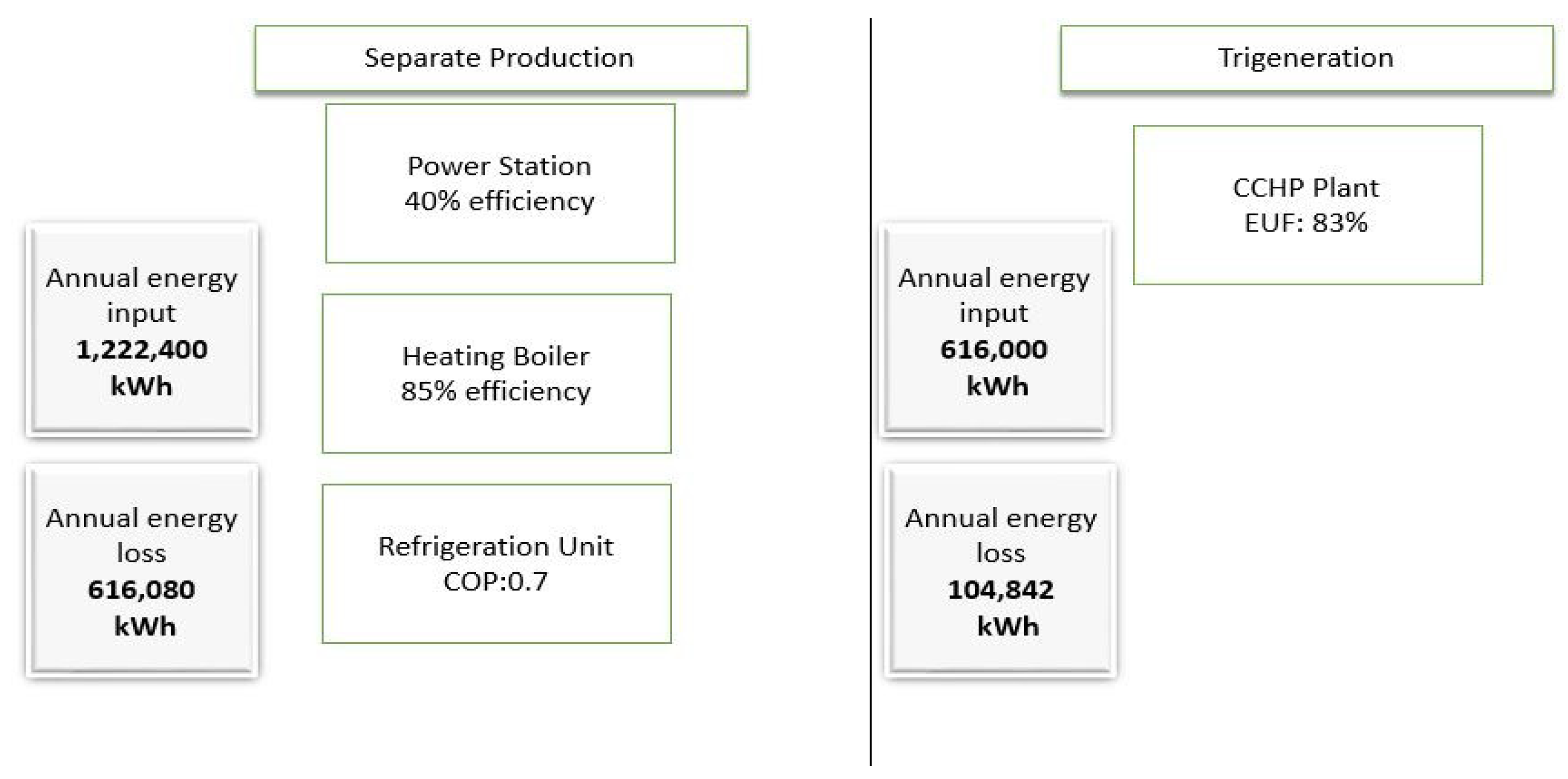
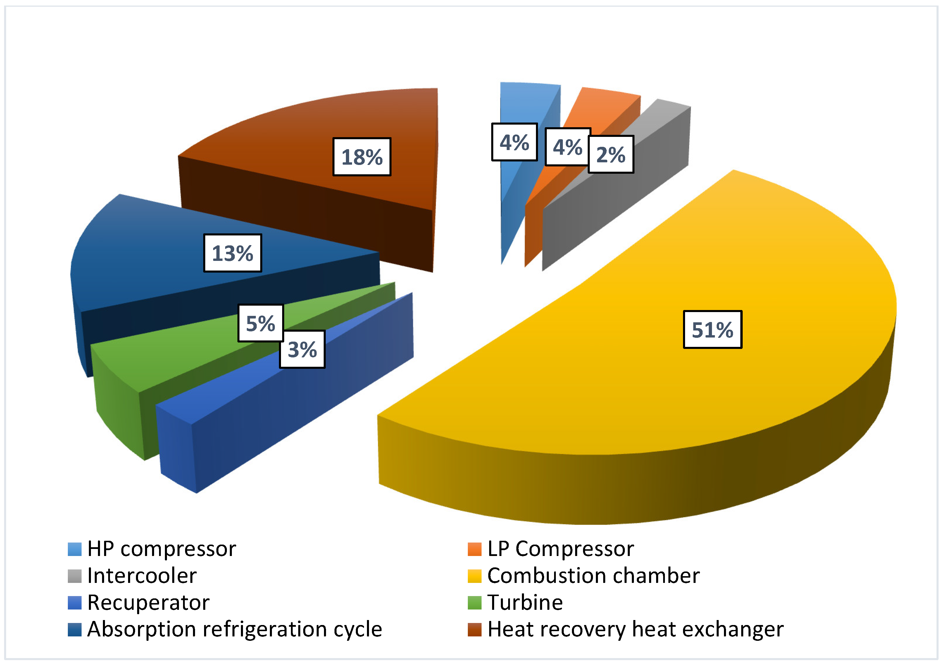
For the base case, the cycle efficiency of the gas turbine is 49.7%; on the other hand, the EUF of the trigeneration system is 83.0%. A major economic benefit for the application of trigeneration technology is generating energy at a lower cost than the cost of purchase from the local energy supplier. Results of the economic analysis show that with the implementation of the proposed combined system, the unit cost of the energy becomes much lower compared to the local grid. The LCOE of the system is around 0.02 $/kWh, whereas the unit price of the local electricity from the grid is 0.09 $/kWh. Compared to a separate production plant, a trigeneration system has 49% lower fuel input. In addition, energy losses through the plant with individual energy and power production are much higher compared to the trigeneration plant. The results of the exergy analysis show that the combustion chamber is the primary source of exergy destruction. Therefore, some measures can be taken to decrease the exergy destruction of that component.
A parametric study was also carried out to investigate the influence of some essential parameters on the system performance. The main findings are summarized below:
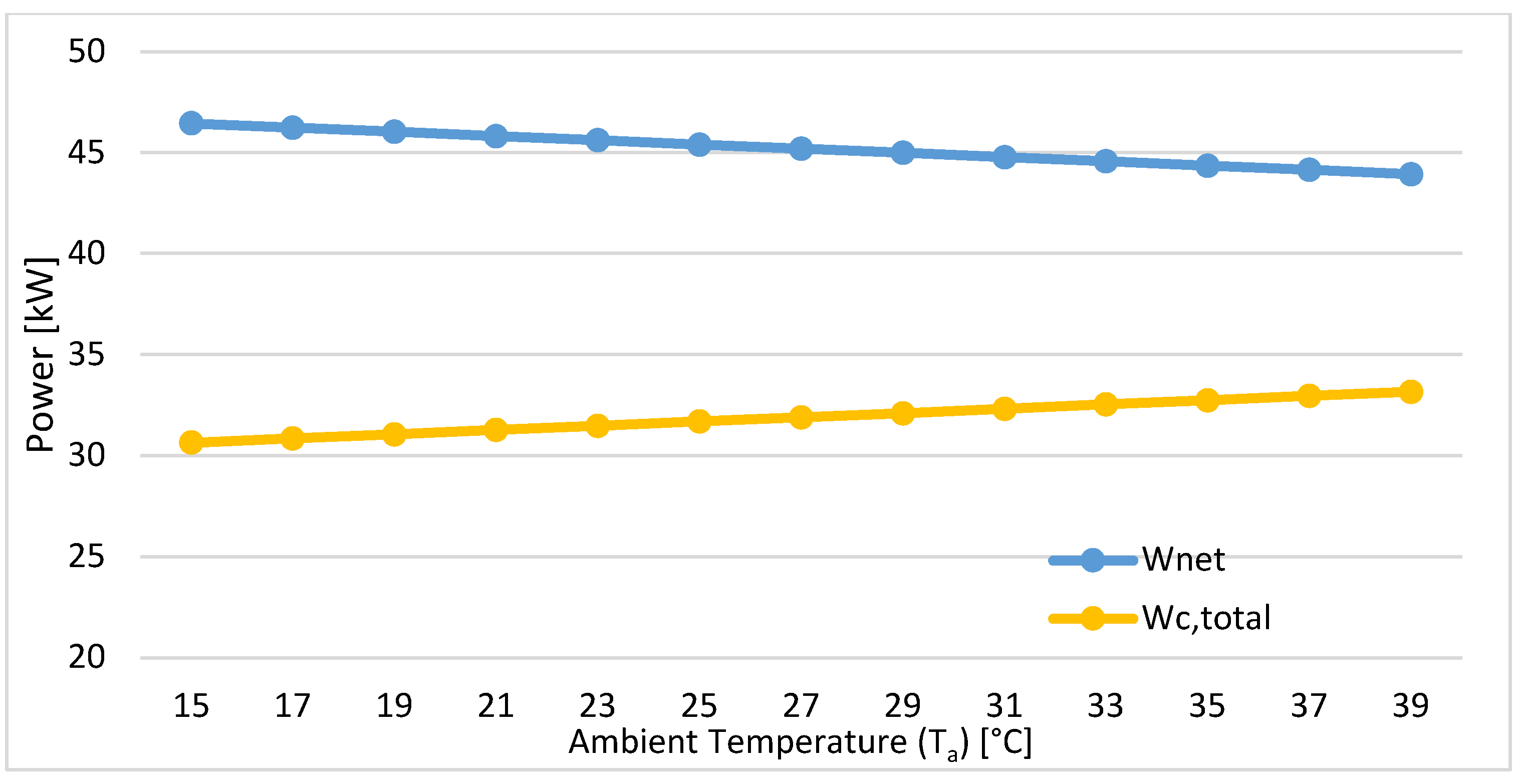
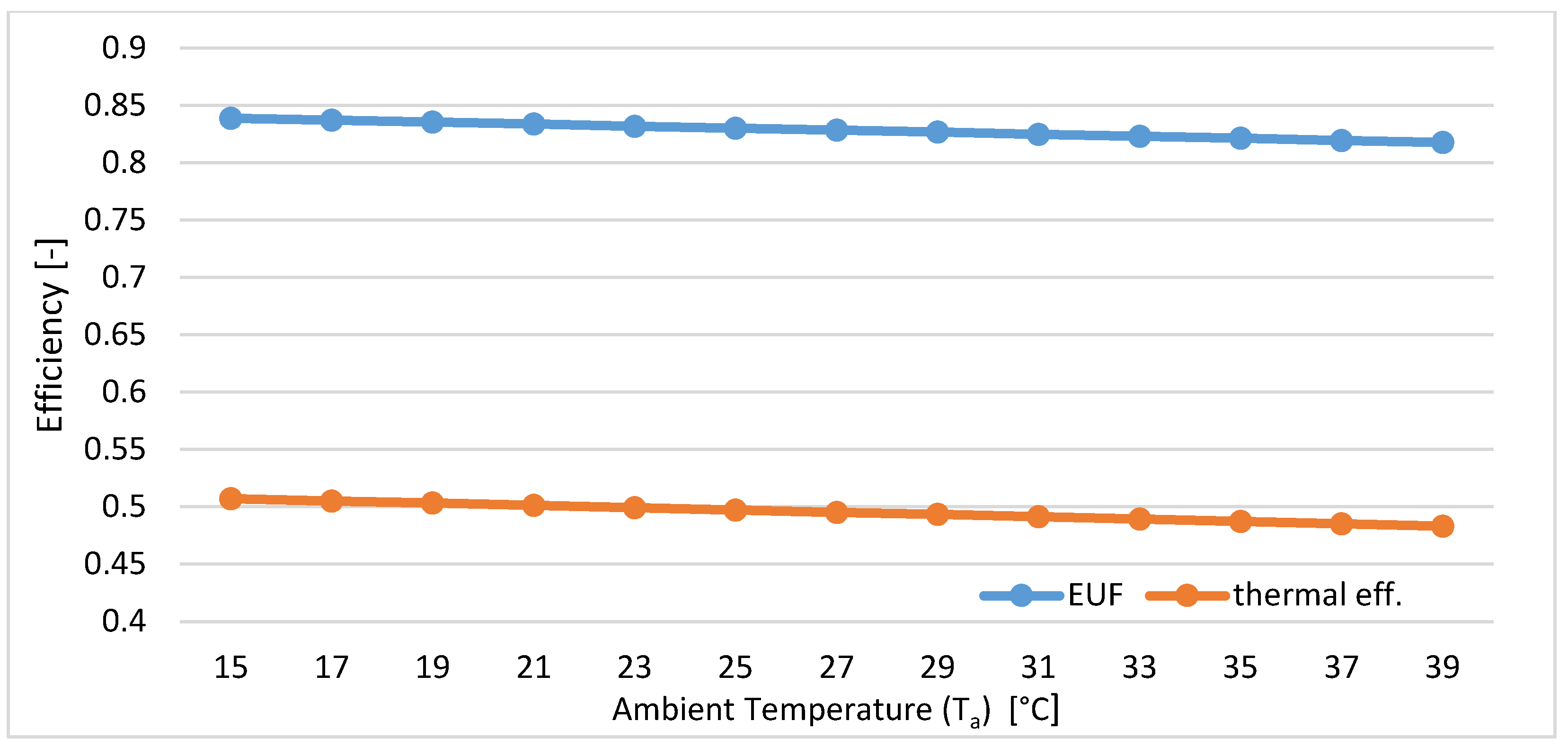
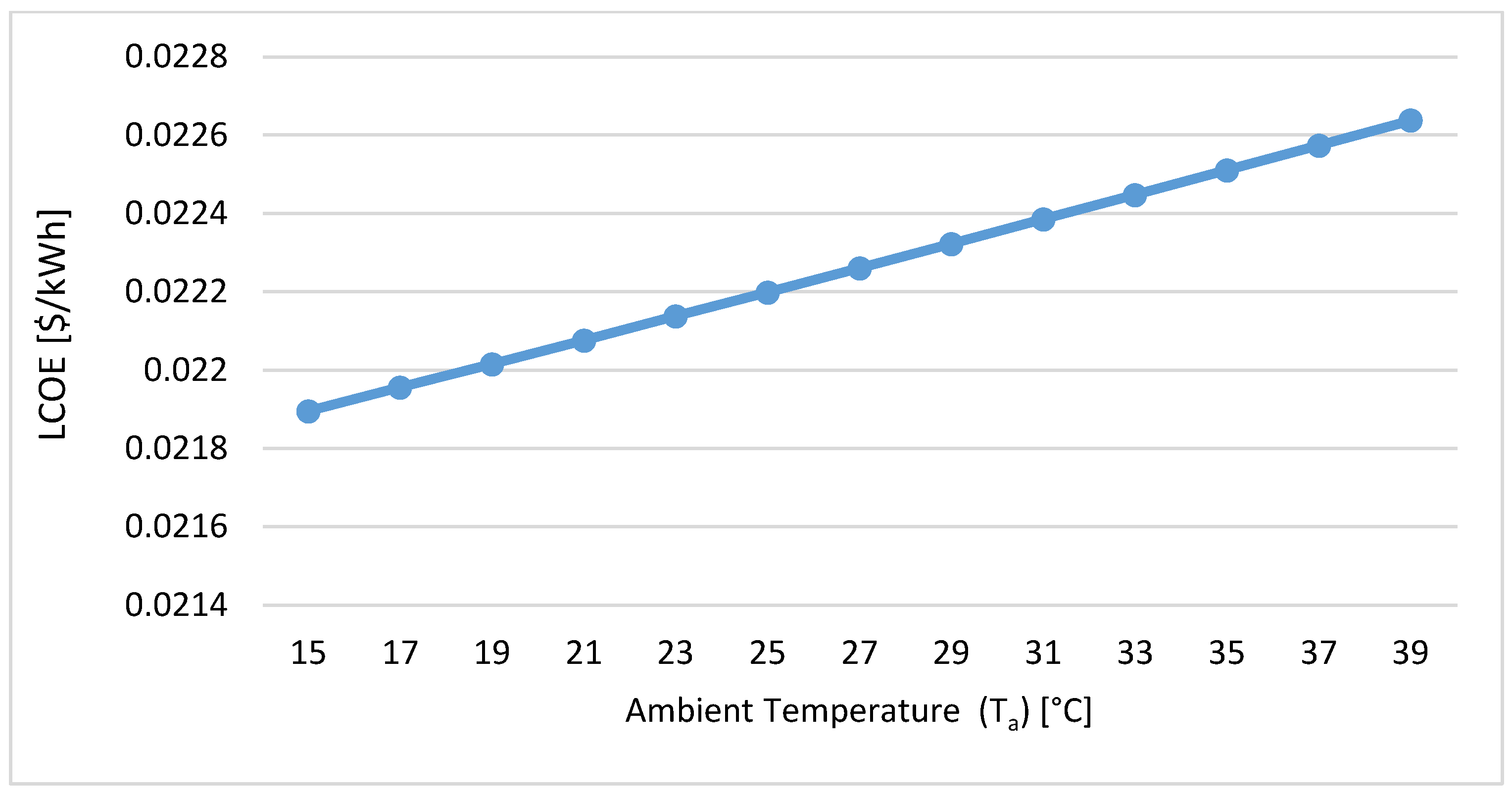
  • Results show that as the ambient temperature rises, the EUF and W ˙ n e t   decrease, and the LCOE of the system increases. The LCOE of the system changes from 0.0219 to 0.0225 $/kWh between 15 and 39 °C ambient temperatures. Therefore, cooling the inlet compressor air with various technologies is an important consideration to improve the thermodynamic performance and financial feasibility of the system.
  • At higher turbine inlet temperatures, fuel mass flow rate and the net power generation increase.
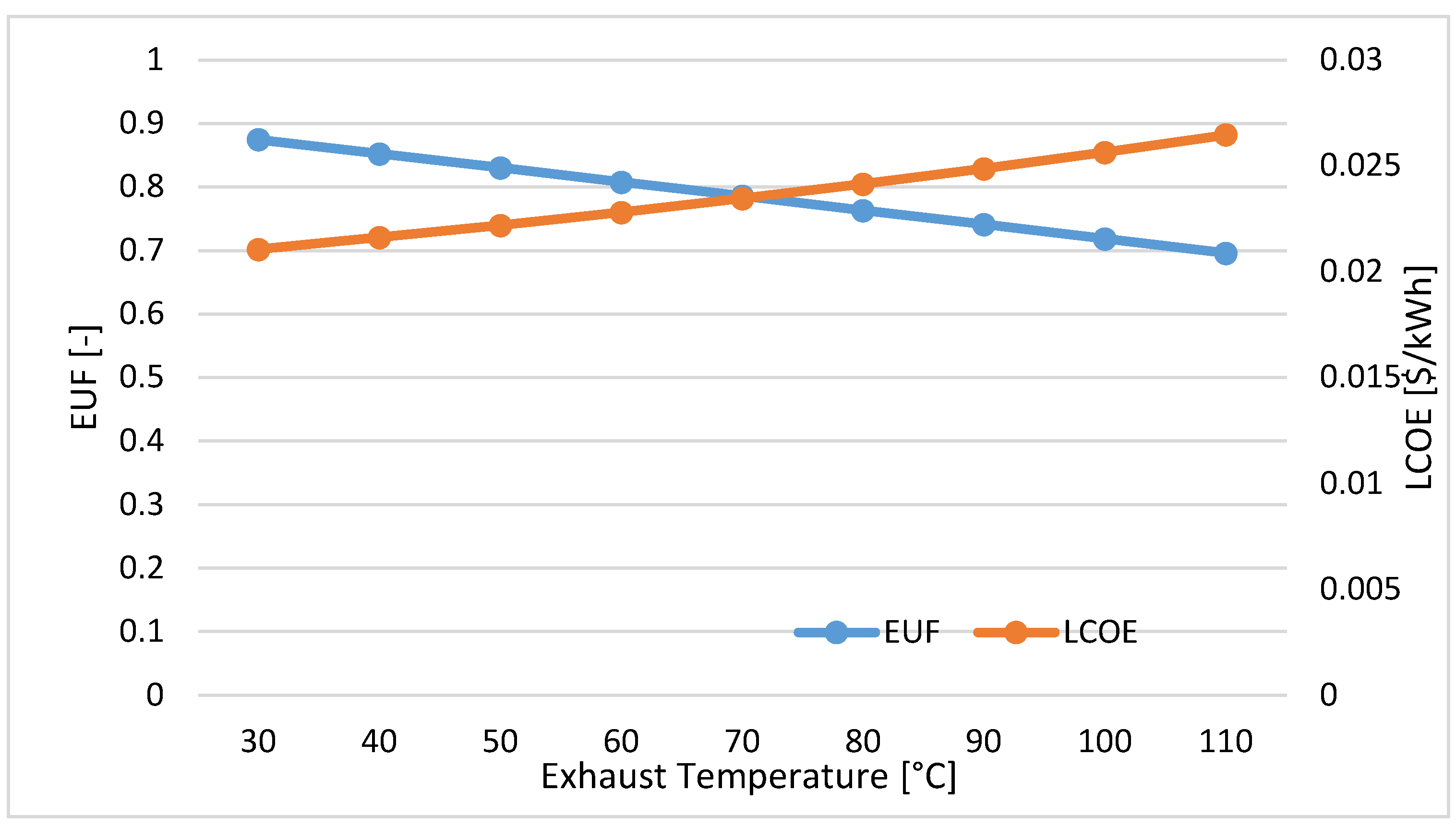
  • Increasing the exhaust temperature decreases the EUF and increases the LCOE. At 30 °C exhaust temperature, the LCOE is at 0.0210 $/kWh, and at 110 °C exhaust temperature, it is at 0.0264 $/kWh. As a result, it is necessary to benefit from the potential of the high-temperature exhaust gas before rejecting it.
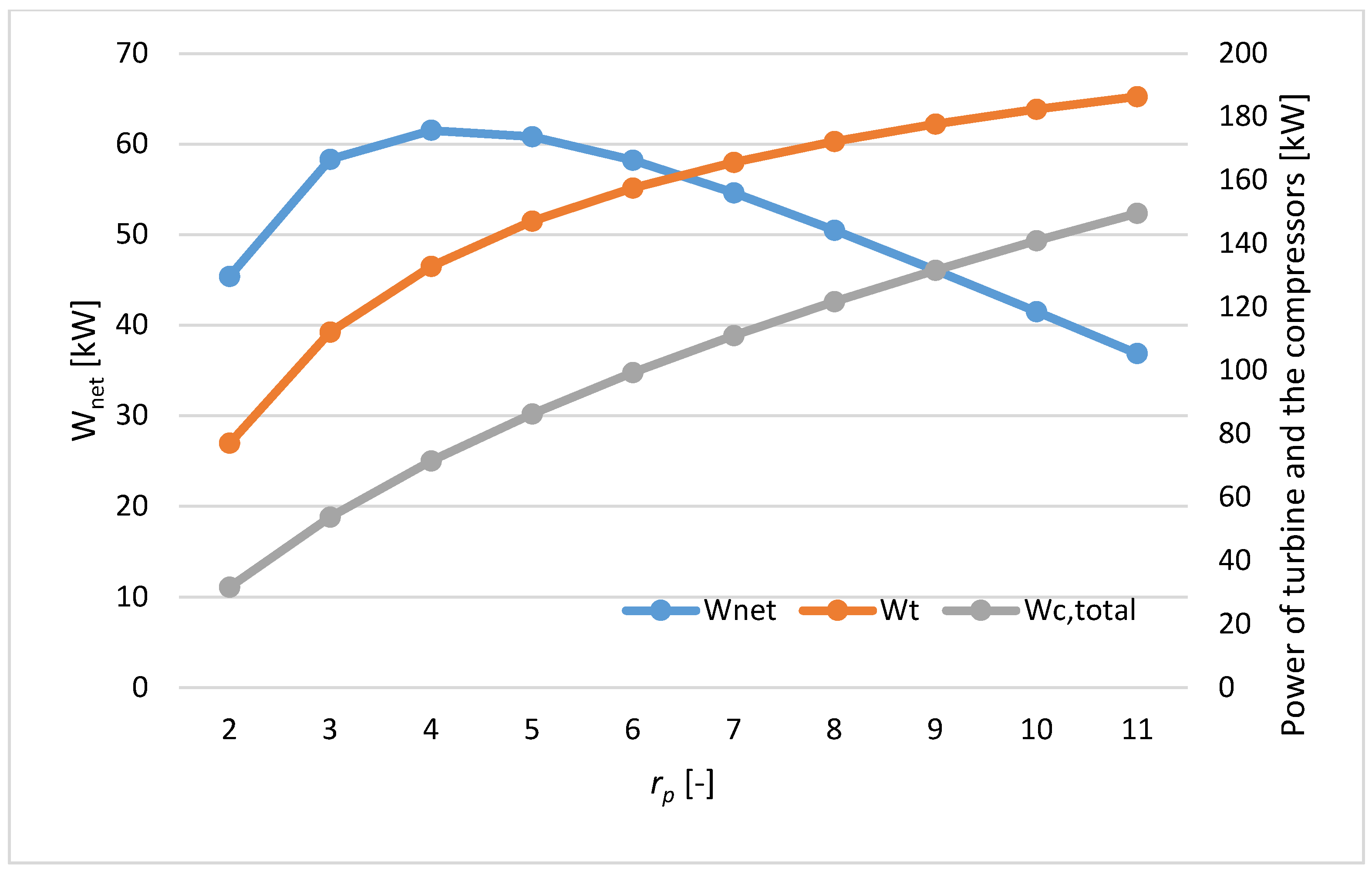
  • When the pressure ratio increases, both turbine and compressor power increase, but after a specific rp value, increments in the compressors’ power consumption are more significant than those for the turbine; as a result, the net power output decreases. The net power utilization of the system is maximum when the rp is 4, for each compressor.
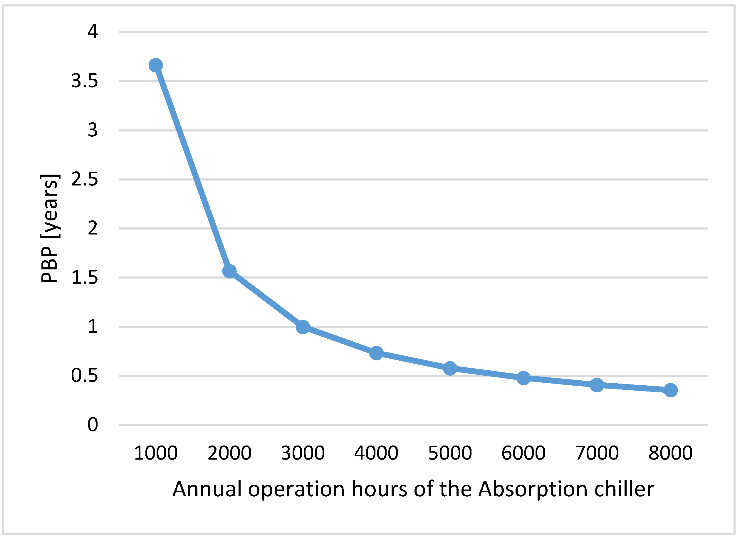
  • The effect of the annual operation hours of the absorption chiller on the payback period of the chiller is investigated. Results show that the integration of an absorption chiller is more beneficial financially when the cooling requirement is high, stable, and continuous. When the annual operation time is 1000 h, the PBP of the chiller is 3.6 years, and it decreases to 4 months when the operation time becomes 8000 h.
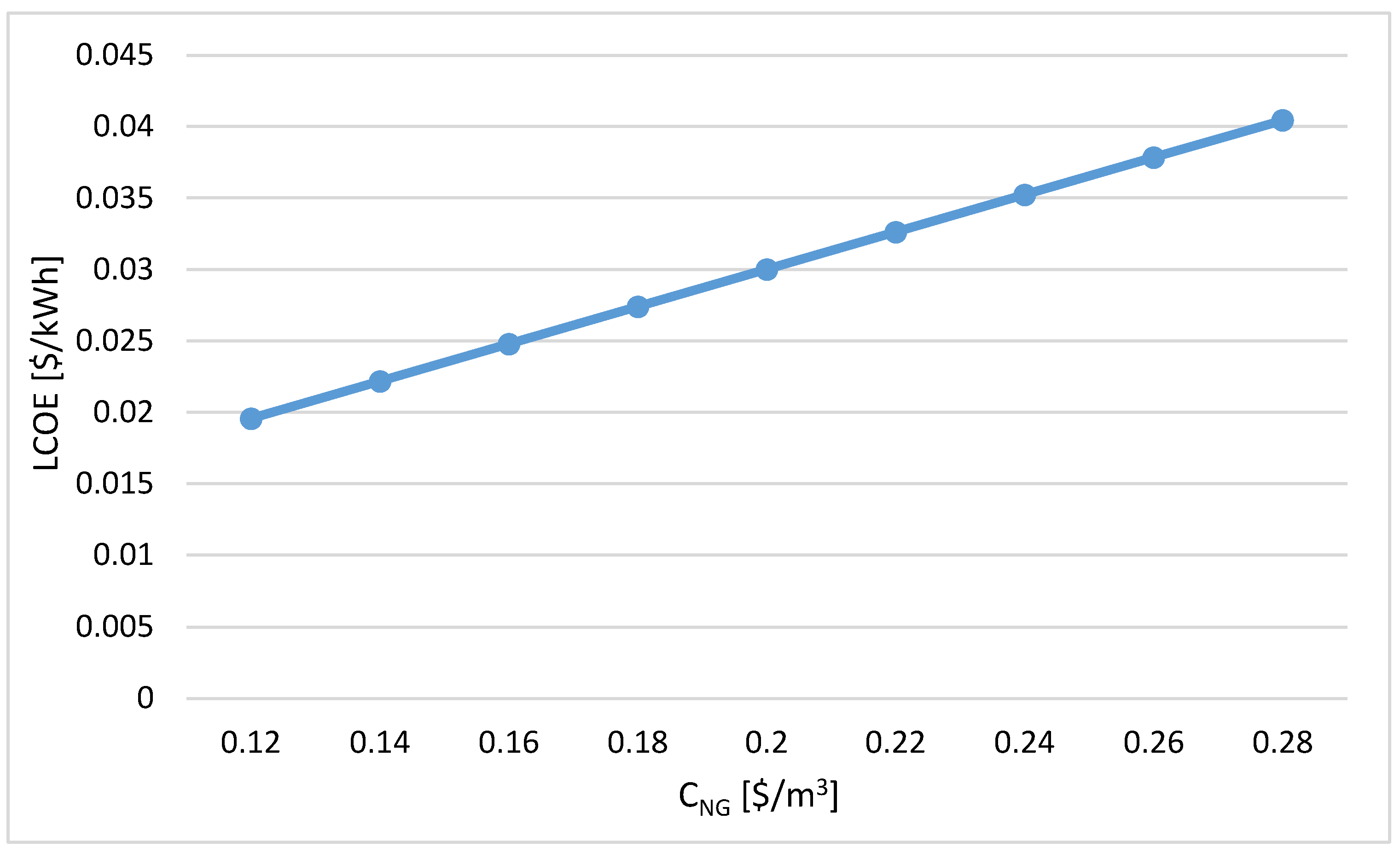
  • Fuel costs have a larger uncertainty in the future market. To reduce the risks, it is important to make accurate fuel price predictions. The effect of the natural gas cost on the LCOE is analyzed. Results show that the LCOE of the combined cycle is very sensitive to the price fluctuations of natural gas. However, even for the most expensive natural gas cost rate scenario, the LCOE of the system is much lower compared to the local electricity rate.
  • Local incentives should be enhanced by regulations to broaden the combined system applications, as the high investment cost is an economic barrier.

Funding

This research received no external funding.

Institutional Review Board Statement

Not applicable.

Informed Consent Statement

Not applicable.

Data Availability Statement

Not applicable.

Conflicts of Interest

The author declares no conflict of interest.

References

  1. Mirzaee, M.; Zare, R.; Sadeghzadeh, M.; Maddah, H.; Ahmadi, M.H.; Acıkkalp, E.; Chen, L. Thermodynamic analyses of different scenarios in a CCHP system with micro turbine—Absorption chiller, and heat exchanger. Energy Convers. Manag. 2019, 198, 111919. [Google Scholar] [CrossRef]
  2. Adhami, H.; Khalilarya, S.; Jafarmadar, S.; Ebrahimi, M. Thermodynamic feasibility study of a suggested portable personal micro trigeneration system based on micro-gas turbine and micro-absorption chiller. Appl. Therm. Eng. 2018, 144, 45–58. [Google Scholar] [CrossRef]
  3. Papadimitriou, A.; Vassiliou, V.; Tataraki, K.; Giannini, E.; Maroulis, Z. Economic assessment of cogeneration systems in operation. Energies 2020, 13, 2206. [Google Scholar] [CrossRef]
  4. Sleiti, A.K.; Al-Ammari, W.A.; Arshad, R.; El Mekkawy, T. Energetic, economic, and environmental analysis of solid oxide fuel cell-based combined cooling, heating, and power system for cancer care hospital. Build. Simul. 2022, 15, 1437–1454. [Google Scholar] [CrossRef]
  5. Wu, Q.; Ren, H.; Gao, W.; Weng, P.; Ren, J. Design and operation optimization of organic Rankine cycle coupled trigeneration systems. Energy 2018, 142, 666–677. [Google Scholar] [CrossRef]
  6. Bellos, E.; Tzivanidis, C. Parametric analysis and optimization of a solar driven trigeneration system based on ORC and absorption heat pump. J. Clean. Prod. 2017, 161, 493–509. [Google Scholar] [CrossRef]
  7. Khaliq, A. Exergy analysis of gas turbine trigeneration system for combined production of power heat and refrigeration. Int. J. Refrig. 2009, 32, 534–545. [Google Scholar] [CrossRef]
  8. Basrawi, F.; Ibrahim, T.K.; Habib, K.; Yamada, T. Effect of operation strategies on the economic and environmental performance of a micro gas turbine trigeneration system in a tropical region. Energy 2016, 97, 262–272. [Google Scholar] [CrossRef]
  9. Buonomano, A.; Calise, F.; D’Accadia, M.D.; Palombo, A.; Vicidomini, M. Hybrid solid oxide fuel cells-gas turbine systems for combined heat and power: A review. Appl. Energy 2015, 156, 32–85. [Google Scholar] [CrossRef]
  10. Khaljani, M.; Khoshbakhti Saray, R.; Bahlouli, K. Comprehensive analysis of energy, exergy and exergo-economic of cogeneration of heat and power in a combined gas turbine and organic Rankine cycle. Energy Convers. Manag. 2015, 97, 154–165. [Google Scholar] [CrossRef]
  11. Thu, K.; Saha, B.B.; Chua, K.J.; Bui, T.D. Thermodynamic analysis on the part-load performance of a microturbine system for micro/mini-CHP applications. Appl. Energy 2016, 178, 600–608. [Google Scholar] [CrossRef]
  12. Wang, Y.; Wu, J.; Mao, X. Exergy Analysis of Cogeneration System for the Wind–Solar–Gas Turbine Combined Supply. Appl. Sol. Energy 2018, 54, 369–375. [Google Scholar] [CrossRef]
  13. Mohammadi, A.; Kasaeian, A.; Pourfayaz, F.; Ahmadi, M.H. Thermodynamic analysis of a combined gas turbine, ORC cycle and absorption refrigeration for a CCHP system. Appl. Therm. Eng. 2017, 111, 397–406. [Google Scholar] [CrossRef]
  14. Javanshir, N.; Seyed Mahmoudi, S.M.; Kordlar, M.A.; Rosen, M.A. Energy and cost analysis and optimization of a geothermal-based cogeneration cycle using an ammonia-water solution: Thermodynamic and thermoeconomic viewpoints. Sustainability 2020, 12, 484. [Google Scholar] [CrossRef]
  15. Urbanucci, L.; Testi, D. Integration of reversible absorption heat pumps in cogeneration systems: Exergy and economic assessment. Energy Convers. Manag. 2019, 200, 112062. [Google Scholar] [CrossRef]
  16. Entezari, A.; Manizadeh, A.; Ahmadi, R. Energetical, exergetical and economical optimization analysis of combined power generation system of gas turbine and Stirling engine. Energy Convers. Manag. 2018, 159, 189–203. [Google Scholar] [CrossRef]
  17. Çakmak, T.; Kılıç, M. The Simulation of a Micro-gas Turbine Cycle and Optimization of the System Components. Uludag Univ. J. Eng. Fac. 2007, 12, 97–108. [Google Scholar]
  18. At, P.; Pentiuc, R.D.; Milici, D. Opportunity Analysis of Cogeneration and Trigeneration Solutions: An Application in the Case of a Drug Factory. Energies 2022, 15, 2737. [Google Scholar] [CrossRef]
  19. Doseva, N.; Chakyrova, D. Energy and exergy analysis of cogeneration system with biogas engines. J. Therm. Eng. 2015, 1, 391–401. [Google Scholar] [CrossRef]
  20. Hoda, A.; Rahman, T.M.R.; Asrar, W.; Khan, S.A. A Comparative Study of Natural Gas and Biogas Combustion in A Swirling Flow Gas Turbine Combustor. Combust. Sci. Technol. 2021, 194, 2613–2640. [Google Scholar] [CrossRef]
  21. Kang, D.W.; Kim, T.S.; Hur, K.B.; Park, J.K. The effect of firing biogas on the performance and operating characteristics of simple and recuperative cycle gas turbine combined heat and power systems. Appl. Energy 2012, 93, 215–228. [Google Scholar] [CrossRef]
  22. Pyo, M.J.; Moon, S.W.; Kim, T.S. A comparative feasibility study of the use of hydrogen produced from surplus wind power for a gas turbine combined cycle power plant. Energies 2021, 14, 8342. [Google Scholar] [CrossRef]
  23. Javadi, M.A.; Khodabakhshi, S.; Ghasemiasl, R.; Jabery, R. Sensivity analysis of a multi-generation system based on a gas/hydrogen-fueled gas turbine for producing hydrogen, electricity and freshwater. Energy Convers. Manag. 2022, 252, 115085. [Google Scholar] [CrossRef]
  24. Najjar, Y.S.H.; Abubaker, A.M. Thermoeconomic analysis and optimization of a novel inlet air cooling system with gas turbine engines using cascaded waste-heat recovery. Energy 2017, 128, 421–434. [Google Scholar] [CrossRef]
  25. Cai, R.; Jiang, L. Analysis of the recuperative gas turbine cycle with a recuperator located between turbines. Appl. Therm. Eng. 2006, 26, 89–96. [Google Scholar] [CrossRef]
  26. Cengel, Y.A.; Boles, M. Thermodynamics an Engineering Approach, 8th ed.; McGraw-Hill Education: New York, NY, USA, 2014; Volume 7, ISBN 9772081415. [Google Scholar]
  27. Matjanov, E. Gas turbine efficiency enhancement using absorption chiller. Case study for Tashkent CHP. Energy 2020, 192, 116625. [Google Scholar] [CrossRef]
  28. Ghafoor, A.; Harijan, K.; Aslam, M.; Ahmed, R. Thermo-environmental and economic analysis of simple and regenerative gas turbine cycles with regression modeling and optimization. Energy Convers. Manag. 2013, 76, 852–864. [Google Scholar] [CrossRef]
  29. Altun, A.F. Design and thermodynamic performance analysis of an ammonia-water absorption refrigeration and microturbine combined system. Uludağ Univ. J. Fac. Eng. 2022, 27, 765–784. [Google Scholar] [CrossRef]
  30. Turan, O.; Aydin, H. Exergetic and exergo-economic analyses of an aero-derivative gas turbine engine. Energy 2014, 74, 638–650. [Google Scholar] [CrossRef]
  31. Chahartaghi, M.; Baghaee, A. Energy & Buildings Technical and economic analyses of a combined cooling, heating and power system based on a hybrid microturbine (solar-gas) for a residential building. Energy Build. 2020, 217, 110005. [Google Scholar] [CrossRef]
  32. Sahin, A.Z.; Al-sharafi, A.; Yilbas, B.S.; Khaliq, A. Overall performance assessment of a combined cycle power plant: An exergo-economic analysis. Energy Convers. Manag. 2016, 116, 91–100. [Google Scholar] [CrossRef]
  33. Shamoushaki, M.; Ehyaei, M.A. Exergy, economic, and environmental (3E) analysis of a gas turbine power plant and optimization by MOPSO algorithm. Therm. Sci. 2018, 22, 2641–2651. [Google Scholar] [CrossRef]
  34. Ebrahimi, M.; Majidi, S. Exergy-energy-environ evaluation of combined cooling heating and power system based on a double stage compression regenerative gas turbine in large scales. Energy Convers. Manag. 2017, 150, 122–133. [Google Scholar] [CrossRef]
  35. Garcia, J.M.; Rosa, A. Theoretical study of an intermittent water-ammonia absorption solar system for small power ice production. Sustainability 2019, 11, 3346. [Google Scholar] [CrossRef]
  36. Al-falahi, A.; Alobaid, F.; Epple, B. Thermo-Economic Evaluation of Aqua-Ammonia Solar Absorption Air Conditioning System Integrated with Various Collector Types. Entropy 2020, 22, 1165. [Google Scholar] [CrossRef]
  37. Klein, S.A. Engineering Equation Solver Manual; F-Chart Software, Box: Madison, WI, USA, 2016; pp. 1–278. Available online: https://www.fchart.com/assets/downloads/ees_manual.pdf (accessed on 20 August 2022).
  38. Seyfouri, Z.; Ameri, M. Analysis of integrated compression-absorption refrigeration systems powered by a microturbine. Int. J. Refrig. 2012, 35, 1639–1646. [Google Scholar] [CrossRef]
  39. Adewusi, S.A.; Zubair, S.M. Second law based thermodynamic analysis of ammonia-water absorption systems. Energy Convers. Manag. 2004, 45, 2355–2369. [Google Scholar] [CrossRef]
  40. Altun, A.F.; Kilic, M. Design and performance evaluation based on economics and environmental impact of a PV-wind-diesel and battery standalone power system for various climates in Turkey. Renew. Energy 2020, 157, 424–443. [Google Scholar] [CrossRef]
  41. Karimi, S.; Mansouri, S. A comparative profitability study of geothermal electricity production in developed and developing countries: Exergoeconomic analysis and optimization of different ORC configurations. Renew. Energy 2018, 115, 600–619. [Google Scholar] [CrossRef]
  42. Rezaei-Shouroki, M.; Mostafaeipour, A.; Qolipour, M. Prioritizing of wind farm locations for hydrogen production: A case study. Int. J. Hydrog. Energy 2017, 42, 9500–9510. [Google Scholar] [CrossRef]
  43. Rezaei, M.; Jafari, N. Wind energy utilization for hydrogen production in an underdeveloped country: An economic investigation. Renew. Energy 2020, 147, 1044–1057. [Google Scholar] [CrossRef]
  44. Gong, L.; Zhang, Y.; Bai, Z. Geothermal-solar hybrid power with the double-pressure evaporation arrangement and the system off-design evaluation. Energy Convers. Manag. 2021, 244, 114501. [Google Scholar] [CrossRef]
  45. Arabkoohsar, A. An integrated subcooled-CAES and absorption chiller system for cogeneration of cold and power. In Proceedings of the 2018 International Conference on Smart Energy Systems and Technologies (SEST), Seville, Spain, 10–12 September 2018; pp. 1–5. [Google Scholar] [CrossRef]
  46. Aksar, M.; Yağlı, H.; Koç, Y.; Koç, A.; Sohani, A.; Yumrutaş, R. Why Kalina (Ammonia-Water) cycle rather than steam Rankine cycle and pure ammonia cycle: A comparative and comprehensive case study for a cogeneration system. Energy Convers. Manag. 2022, 265, 115739. [Google Scholar] [CrossRef]
  47. Haghighat, A.; Alberto, S.; Escandon, A.; Naja, B.; Shirazi, A.; Rinaldi, F. Techno-economic feasibility of photovoltaic, wind, diesel and hybrid electri fi cation systems for off-grid rural electri fi cation in Colombia. Renew. Energy 2016, 97, 293–305. [Google Scholar] [CrossRef]
  48. Behnam, P.; Arefi, A.; Shafii, M.B. Exergetic and thermoeconomic analysis of a trigeneration system producing electricity, hot water, and fresh water driven by low-temperature geothermal sources. Energy Convers. Manag. 2018, 157, 266–276. [Google Scholar] [CrossRef]
  49. Abedi, M.R.; Salehi, G.; Azad, M.T.; Manesh, M.H.K.; Fallahsohi, H. Exergetic and exergoeconomic analysis and optimization of gas turbine inlet air cooling systems with absorption or compression chilling. Int. J. Thermodyn. 2021, 24, 93–107. [Google Scholar] [CrossRef]
  50. Liu, X.; Zeng, Z.; Hu, G.; Asgari, A. Thermodynamic, environmental, and economic analysis of a novel power and water production system driven by gas turbine cycle. Alexandria Eng. J. 2022, 61, 9529–9551. [Google Scholar] [CrossRef]
  51. Capstone C65 Microturbine Data Sheet. Available online: https://www.pureworldenergy.com/media/filer_public/b3/7e/b37e3586-9e71-492a-9190-0cd6e92c3619/c65_ichp_hpng_331072b_lowres.pdf (accessed on 18 August 2022).
  52. Wang, J.; Wang, J.; Zhao, P.; Dai, Y. Thermodynamic analysis of a new combined cooling and power system using ammonia-water mixture. Energy Convers. Manag. 2016, 117, 335–342. [Google Scholar] [CrossRef]
Figure 2. Comparison of the separate energy production and trigeneration.
Sustainability 14 11820 g002
Figure 3. The exergy destruction percentage of the system components.
Sustainability 14 11820 g003
Figure 5. The EUF and the thermal efficiency of the power cycle ( η t ) against different ambient temperatures.
Sustainability 14 11820 g005
Figure 6. The LCOE of the system against varying ambient temperatures.
Sustainability 14 11820 g006
Figure 7. Impact of turbine inlet temperature on net power generation ( W ˙ n e t ) and fuel consumption ( m ˙ f ).
Sustainability 14 11820 g007
Figure 8. Impact of exhaust temperature on the EUF and the LCOE.
Sustainability 14 11820 g008
Figure 9. Impact of pressure ratio on the net power generation ( W ˙ n e t ) and the capacity of the turbine ( W ˙ t ) and the compressors ( W ˙ c , t o t a l ).
Sustainability 14 11820 g009
Figure 10. The payback period (PBP) of the absorption chiller against the annual operation hours.
Sustainability 14 11820 g010
Figure 11. The LCOE of the system for varying natural gas rates.
Sustainability 14 11820 g011
Table 1. Energy relation of the system components.
ComponentEnergy Relation
Absorption refrigeration system
Evaporator Q ˙ e v a p = m ˙ r e f × ( h 13 h 12 )
Absorber Q ˙ a b s = ( m ˙ r e f × h 14 ) + ( m ˙ g e n × h 6 ) ( m ˙ a b s × h 1 )
Solution Heat Exchanger (SHX) Q ˙ S H X = ε S H X × C m i n × T 4 T 2
Generator Q ˙ g e n = ( m ˙ 7 × h 7 ) + ( m ˙ g e n × h 4 ) ( m ˙ a b s × h 3 ) ( m ˙ 8 × h 8 )
Rectifier Q ˙ r e c t = ( m ˙ 7 × h 7 ) ( m ˙ r e f × h 9 ) ( m ˙ 8 × h 8 )
Condenser Q ˙ c o n d = m ˙ r e f × ( h 9 h 10 )
Refrigerant Heat Exchanger (RHX) Q ˙ R H X = ε R H X × C m i n × T 10 T 13 ;
C m i n = min ( C 23 , C 45 )
Solution Pump W ˙ p u m p = m ˙ a b s × ( h 2 h 1 )
Power cycle
Low-Pressure Compressor W ˙ L P C = m ˙ a i r x ( h 26 h 25 )
High-Pressure Compressor W ˙ H P C = m ˙ a i r x ( h 28 h 27 )
Intercooler Q ˙ i c = m ˙ 26 × ( h 26 h 27 ) = m ˙ 19 × ( h 20 h 19 )
Recuperator Q ˙ r e c = m ˙ 28 × ( h 29 h 28 ) = m ˙ 32 × ( h 32 h 33 )
Combustion Chamber Q ˙ c b = L H V N G × m ˙ f × η c b
Turbine W ˙ T = m ˙ 31 × ( h 31 h 32 )
Hot water system
Heat Recovery Heat Exchanger (HRHX) Q ˙ H R H X = m ˙ 34 × ( h 34 h 35 )
Table 2. Exergy relation of the system components.
ComponentExergy Relation
Absorption refrigeration system
Evaporator E ˙ e v a p = ( E ˙ 21 E ˙ 22 ) + ( E ˙ 12 E ˙ 13 )
Absorber E ˙ a b s = ( E ˙ 15 E ˙ 16 ) + ( E ˙ 14 + E ˙ 6 E ˙ 1 )
Solution Heat Exchanger (SHX) E ˙ S H X = ( E ˙ 2 E ˙ 3 ) + ( E ˙ 4 E ˙ 5 )
Generator E ˙ g e n = ( E ˙ 3 E ˙ 4 ) + ( E ˙ 8 E ˙ 7 ) + ( E ˙ 33 E ˙ 34 )
Rectifier E ˙ r e c t = ( E ˙ 18 E ˙ 19 ) + ( E ˙ 7 E ˙ 9 E ˙ 8 )
Condenser E ˙ c o n d = ( E ˙ 17 E ˙ 18 ) + ( E ˙ 9 E ˙ 10 )
Refrigerant Heat Exchanger (RHX) E ˙ R H X = ( E ˙ 10 E ˙ 11 ) + ( E ˙ 13 E ˙ 14 )
Solution Pump E ˙ p u m p = ( E ˙ 1 E ˙ 2 ) + W ˙ P
Refrigerant Expansion Valve (REV) E ˙ R E V = ( E ˙ 11 E ˙ 12 )
Solution Expansion Valve (SEV) E ˙ S E V = ( E ˙ 5 E ˙ 6 )
Power cycle
Low-Pressure Compressor E ˙ L P C = W ˙ L P C + E ˙ 25 E ˙ 26
High-Pressure Compressor E ˙ H P C = W ˙ H P C + E ˙ 27 E ˙ 28
Intercooler E ˙ I C = ( E ˙ 26 E ˙ 27 ) + ( E ˙ 19 E ˙ 20 )
Recuperator E ˙ R e c = ( E ˙ 28 E ˙ 29 ) + ( E ˙ 32 E ˙ 33 )
Combustion Chamber E ˙ C B = E ˙ 29 E ˙ 31 + E ˙ 30
Turbine E ˙ T = E ˙ 31 E ˙ 32 W ˙ T
Hot water system
Heat Recovery Heat Exchanger (HRHX) E ˙ H R H X = ( E ˙ 34 E ˙ 35 ) + ( E ˙ 24 E ˙ 23 )
Table 3. Main assumptions for the combined system.
ParameterValue
Ambient temperature (°C)25
The temperature at the turbine inlet (°C)1000
Pump isentropic efficiency (%)0.5
Isentropic efficiency of the compressor0.85
The mass flow rate of the air at the LPC (kg/s)0.2
The mass flow rate of the domestic hot water (kg/s)0.1
Isentropic efficiency of the turbine (-)0.9
The pressure ratio of the compressors (-)2
Effectiveness of the intercooler (-)0.9
Effectiveness of the recuperator (-)0.9
Effectiveness of the RHX (-)0.95
Effectiveness of the SHX (-)0.95
Combustion efficiency (-)0.95
Evaporation temperature in cooling cycle (°C)0
Absorption temperature in cooling cycle (°C)40
Desorption temperature in the cooling cycle (°C)120
The temperature of the air at the HRHX exit (°C)50
Table 7. Investigated cases in the present study.
Simulation CaseInvestigated Value Ranges
Ambient temperature (Ta)15–39 °C
Turbine inlet temperature (T31)500–1100 °C
Exhaust temperature (T35)30–110 °C
Pressure ratio (rp)2–11
Natural gas prices (CNG)0.12–0.28 $/m3
Table 10. The CCHP thermodynamic state in Ta = 20 °C.
StateT (°C)P (kPa)h (kJ/kg) m ˙   ( k g / s ) s (kJ/kg K)
140409.2−59.420.056940.4434
240.411556−56.650.056940.4478
3100.31556214.30.056941.239
41201556333.30.044941.509
544.391556−10.040.044940.5385
643.08409.2−10.040.044940.5426
789.47155614620.012494.668
889.471556166.50.00049181.109
945.13155613110.0124.223
10401556190.70.0120.6579
1118.88155688.310.0120.3194
12−1.273409.288.310.0120.3367
130409.212610.0124.629
1438409.213630.0124.981
1525400105.20.92280.3671
1630400126.10.92280.4366
1725400105.20.42250.3671
1832.614001370.42250.4724
1934400142.80.42250.4914
2040.97400171.90.42250.5851
211540063.360.3360.2244
22540021.420.3360.07625
2364.05400268.40.10.8816
2425400105.21.5450.3671
2525298.4298.40.26.86
26101.7375.5375.50.26.891
2737.17310.4310.40.26.7
28116.9390.7390.70.26.732
29615.5920.7920.70.27.601
3025500-0.001923-
311000136513650.20198.021
32670.9982.9982.90.20198.067
33231.6508.2508.20.20197.394
34130404.4404.40.20197.164
3550323.5323.50.20196.941
Table 11. Performance of the combined system.
TermValueUnit
The power output of the turbine77.09kW
Power consumption of the LP compressor15.43kW
Power consumption of the HP compressor16.25kW
The net power output of the system45.4kW
Cooling rate14.07kW
The mass flow rate of the fuel ( m ˙ f )6.916kg/h
The capacity of the HRHX16.32kW
Energy utilization factor (EUF)0.8301-
The thermal efficiency of the power cycle ( η t ) 0.4972-
COP0.6662-
Table 12. Exergy destruction of the components.
Component E ˙ d e s t   [ kW ]
Power cycle
HP compressor1.871
LP compressor1.870
Intercooler1.130
Combustion chamber26.260
Recuperator1.306
Turbine2.760
TOTAL35.197
Absorption refrigeration cycle
Rectifier0.1692
RHX0.04902
SHX0.4291
Condenser0.516
Evaporator0.5385
Pump0.07484
Generator4.833
Absorber0.1746
Solution expansion valve0.05533
Refrigerant expansion valve0.06172
TOTAL6.901
Hot water cycle
Heat recovery heat exchanger9.282
Publisher’s Note: MDPI stays neutral with regard to jurisdictional claims in published maps and institutional affiliations.

