Article

A Hydrogen-Fueled Micro Gas Turbine Unit for Carbon-Free Heat and Power Generation

Faculty of Science and Technology, University of Stavanger, 4021 Stavanger, Norway
*
Author to whom correspondence should be addressed.
Sustainability 2022, 14(20), 13305; https://doi.org/10.3390/su142013305
Submission received: 30 August 2022 / Revised: 4 October 2022 / Accepted: 6 October 2022 / Published: 16 October 2022

Abstract

:
The energy transition with transformation into predominantly renewable sources requires technology development to secure power production at all times, despite the intermittent nature of the renewables. Micro gas turbines (MGTs) are small heat and power generation units with fast startup and load-following capability and are thereby suitable backup for the future’s decentralized power generation systems. Due to MGTs’ fuel flexibility, a range of fuels from high-heat to low-heat content could be utilized, with different greenhouse gas generation. Developing micro gas turbines that can operate with carbon-free fuels will guarantee carbon-free power production with zero CO2 emission and will contribute to the alleviation of the global warming problem. In this paper, the redevelopment of a standard 100-kW micro gas turbine to run with methane/hydrogen blended fuel is presented. Enabling micro gas turbines to run with hydrogen blended fuels has been pursued by researchers for decades. The first micro gas turbine running with pure hydrogen was developed in Stavanger, Norway, and launched in May 2022. This was achieved through a collaboration between the University of Stavanger (UiS) and the German Aerospace Centre (DLR). This paper provides an overview of the project and reports the experimental results from the engine operating with methane/hydrogen blended fuel, with various hydrogen content up to 100%. During the development process, the MGT’s original combustor was replaced with an innovative design to deal with the challenges of burning hydrogen. The fuel train was replaced with a mixing unit, new fuel valves, and an additional controller that enables the required energy input to maintain the maximum power output, independent of the fuel blend specification. This paper presents the test rig setup and the preliminary results of the test campaign, which verifies the capability of the MGT unit to support intermittent renewable generation with minimum greenhouse gas production. Results from the MGT operating with blended methane/hydrogen fuel are provided in the paper. The hydrogen content varied from 50% to 100% (volume-based) and power outputs between 35kW to 100kW were tested. The modifications of the engine, mainly the new combustor, fuel train, valve settings, and controller, resulted in a stable operation of the MGT with NOx emissions below the allowed limits. Running the engine with pure hydrogen at full load has resulted in less than 25 ppm of NOx emissions, with zero carbon-based greenhouse gas production.

1. Introduction

The global warming caused by CO2 emissions from anthropogenic activities is threatening life on earth. Intermittent renewables, such as wind and solar energy, are foreseen to provide the largest increase in renewable power generation as the most important contributors to sustainable development. The paradigm change, from today’s energy system to the future’s carbon-free version based on intermittent renewables, can be formulated as the power will be generated when possible, not when needed. However, the intermittent nature of these energy sources is already causing grid instability, which will become even more severe when their share in the power mix will further increase in the near future. Therefore, fuel-flexible, dispatchable energy conversion technologies and energy storage will be needed to bridge the gap caused by the intermittency of the renewables, such as wind and solar.
Distributed energy generation (DEG) facilitates the use of different energy sources. Since distributed power is generated at or near the point of use, transfer losses can be reduced, and small heat sinks close to end-users can be utilized resulting in considerable efficiency improvements and reduction in emissions. The characteristics of micro gas turbines, i.e., reliability and low maintenance, along with their fuel flexibility and load-following capability have made them an interesting option for combined heat and power generation and a prime mover for competitive, secure and sustainable micro-scale poly-generation [1]. In fact, MGTs can operate on a range of fuels, from high heating values such as methane to low heating value fuels such as biogas [2]. The combustion systems of micro gas turbines can also be designed so that they can burn fuels with lower octane numbers and heavier hydrocarbon components [3,4]. This applies also to fuels containing hydrogen [5].
Fuel flexible, distributed generation units that can utilize locally available resources to provide heat and power on demand, will be of paramount importance for the realization of sustainable energy solutions. Therefore, experimental studies for technology verification and the provision of data for model validation are needed to support this development. Utilizing hydrogen or hydrogen blends has become an important issue for carbon-free power generation. Various challenges are associated with developing and/or modifying the engine components to manage the variable volume flow of the fuel and the changing flame structure and kinetics due to hydrogen combustion [6,7]. However, evaluating the system operation with a large portion of the hydrogen in the fuel blend is a concern for which just a limited number of publications are available in the open literature.
The journey of driving gas turbines with hydrogen-enriched fuels began decades ago. In 1939, Hans von Ohain tested a prototype of a gas turbine that was supplied with hydrogen from an externally pressurized source. The smooth and fast combustion of hydrogen was observed while metal burnout was reported as an obstacle [7]. A combustor prototype for a micro gas turbine was developed by Minakawa et al. [8] to run with pure hydrogen. The combustor was a lean premixed swirling type, and it was tested in atmospheric pressure conditions, resulting in efficient combustion and low NOx emissions. The prototype was later assembled on an MGT which resulted in flashbacks during the startup. This issue, which was unforeseen during the component test, was addressed by modifying the air inlet to the combustor [8]. One of the first publications reporting the measurements of hydrogen injection into a heavy-duty gas turbine was provided by Morris et al. [9] in 1998. An immediate reduction in CO emissions and a slight increase in NOx production were observed by hydrogen injection up to 10% in the fuel.
With the development of computers over the years, researchers pursued modeling and simulation of combustion with hydrogen to reduce experimental costs and attain a deep understanding of the phenomena. Combustion of hydrogen/methane-blended fuels in a micro gas turbine was studied by Shih et al. utilizing computational fluid dynamic (CFD) methods [10]. In their research, the effect of hydrogen on flame structure and emissions were investigated by adding hydrogen from 0 to 90% on volume bases. The authors concluded that although simulation results indicate a stable combustion performance, modifications to the original combustor will be required to address the emissions of the combustor with a high hydrogen content [10]. Experiments, as well as numerical investigations, were conducted by Rajpara et al. [11] to assess the effect of hydrogen injection on a gas turbine burning methane, upstream of the swirl combustor. Increasing hydrogen content resulted in smaller flame dimensions with an increase in NOx emissions due to higher flame temperature but a decrease in CO emissions. Cappelletti et al. [12] investigated the combustion of pure hydrogen in a lean premix burner with experimental and numerical simulations. The experimental setup was built based on an existing burner from a heavy-duty gas turbine, which was modified to enable variable premixing levels. With hydrogen combustion, high flow velocity was required to avoid the flame positioning inside the pre-mixer duct. The results of their work confirmed the possibilities of developing combustion technology with pure hydrogen fuel while keeping the emissions below the regulated limits. Binesh et al. [13] performed a series of experiments to investigate the combustion behavior of hydrogen-enriched methane fuel in a swirl-stabilized model gas-turbine combustor. The amount of hydrogen in the blended fuel was increased up to 80% in volume and during their test, the upper and lower limits of air to maintain stable combustion were derived.
In May 2020, Kawasaki announced a successful test of an industrial gas turbine with hydrogen fuel, through their dry low emission combustion technology. The combustor applies micro-mix combustion technology, which features ultra-small hydrogen-fueled flames and achieves low NOx combustion without using water or steam, which is beneficial in terms of cycle efficiency [14,15].
This paper presents the experimental setup of a test rig in Stavanger, Norway, utilizing a T100 micro gas turbine in combined heat and power (CHP) mode. As the reviewed literature shows, the goal of operating micro gas turbines has been pursued for decades, however, the successful operation of a micro gas turbine with high (up to 100%) content of hydrogen was not achieved before. In fact, burning high hydrogen content fuels was investigated in two ways, either numerical or experiments with combustor test rigs to focus on combustion phenomena. The stable combustion was achieved in most of the combustor test rigs at the atmospheric condition which fails to imitate the real pressure conditions in an engine. Furthermore, a test rig that is specified for a combustor, fails to simulate the interaction between the combustor and other components, different operating conditions of the engine, the transitions, and how they all affect the combustion of the hydrogen-enriched fuel.
This paper provides insights into the application of hydrogen-enriched fuel on a commercial micro gas turbine. The complications of running the engine in part-loads and base-load operations have been addressed. The transitions between loads are crucial situations in the engine, where the varying fuel flow rate and rotational speed in the engine will impact the air/fuel ratio in the combustor and the main flow rate through the engine as well. The complications of hydrogen combustion have a destructive effect on the performance of the engine, which has been encountered during the current endeavor and undertaken via design modifications and controller optimization.
The structure of the paper is as follows: first, an overview of the main challenges with hydrogen combustion is provided. Secondly, the engine setup is presented, with a focus on technology modifications, overcoming the issues of hydrogen combustion. The preliminary results from engine operation with various mixtures of methane and hydrogen are also presented which verifies the presented technology.

2. Problem Formulation

Developing a gas turbine engine to run with hydrogen is accompanied by numerous challenges; especially when the goal is to accommodate the variable content of the hydrogen blend with carbon-based fuels. The difference in characteristics of hydrogen and hydrocarbon (in this case, methane) leads to different combustion characteristics which must be considered during the designing process of the combustor and fuel delivery system. Reviewing numerous studies on combustion with hydrogen, a summary of these characteristics is provided in the following subsections.

2.1. Combustion Kinetics

Hydrogen has higher flammability and a lower ignition temperature. In fact, the low ignition temperature of hydrogen together with the high flame propagation speed and high flame temperature could improve the conditions for maintaining stable combustion in low-load ranges of gas turbines operation, also lower the risk of flame-out in lean combustion conditions [16,17,18,19,20]. The higher speed of hydrogen flame in comparison with methane can cause flashbacks, in which the flame sits in unwanted locations and could result in component damage. Part-load operations are more prone to flashbacks, therefore careful consideration for controlling the airflow during the operation is required to avoid flashbacks [21].

2.2. Flame Temperature

The adiabatic flame temperature of hydrogen combustion is higher than methane and their differences increase as the combustion becomes richer [22,23]. Adding hydrogen to methane will also increase the adiabatic flame temperature since hydrogen will accelerate the reaction rate [16,24]. In Figure 1, the adiabatic flame temperature of burning methane and hydrogen is compared with each other. The air/fuel mixture in the calculation is assumed to be at 4.3 bar pressure and 630 K temperature, which is the condition of the air entering the combustor when the MGT is running at the baseload. As it is evident from the figure, the richer the combustion is, the larger the difference between the adiabatic flame temperature of methane and hydrogen becomes. However, in very lean air/fuel mixes, the adiabatic temperature of methane and hydrogen are very close to each other.

2.3. NOx Emissions

One of the main concerns of hydrogen combustion is the production of toxic nitrogen oxides due to high temperatures. The nitrogen molecule present in the air reacts with oxygen in high temperature conditions. The NOx production begins when the temperature reaches above 1000 °C and the rate of production increases rapidly with further increase in the temperature [25]. One of the common ways of preventing NOx emissions in gas turbines is to use lean premixed burners or dry low NOx burners, where the fuel is premixed with the air prior to the combustion, to keep the flame temperature below a certain value [26]. The main concerns with lean premixed burners are providing stable conditions for combustion, avoiding flashbacks, and thermo-acoustic instabilities [27,28]. These issues become more complicated when using hydrogen and methane blends. The established technology designed for hydrocarbon-based fuels is not adequate for hydrogen blends, especially with high hydrogen contents. With a big difference in flammability range and reaction rates of hydrogen from hydrocarbons, the ignition in combustors will occur before the fuel is adequately mixed with air which results in high temperatures and promotes NOx emissions. Dilution with steam and water is another method employed in gas turbines to alleviate the combustion temperature and NOx production, which is not the best solution since it has a destructive effect on cycle efficiency because of the evaporation of water spray in the hot combustion gas. Besides, dilution with water and steam could cause thermal stress which affects the material integrity of the components. Moreover, high quality water will be required which will increase the costs.

2.4. Different Combustion Products

The replacement of carbon atoms with hydrogen when hydrogen is added to the fuel will result in different combustion products. Burning methane will produce carbon dioxide and water, while the products of hydrogen combustion will be only water (steam). Therefore, hydrogen combustion will result in a higher content of water (steam) in flue gas than when methane is combusted. Burning the fuels with air assuming the two main components of it (nitrogen and oxygen) will be as described in Equations (1) and (2):
CH 4 + 2 ( O 2 + 3.76 N 2 )   CO 2 + 2 H 2 O + 7.52 N 2
2 H 2 + ( O 2 + 3.76 N 2 )   2 H 2 O + 3.76 N 2
This is when we are assuming complete combustion, however, the reality includes other products as the combustion is not complete. Carbon monoxide, nitrogen oxides, and even radicals could be in the product mix. Adding hydrogen to the fuel could improve the combustion efficiency and reduce the share of these products, as it increases the flame temperature [29].
To evaluate the effect of adding hydrogen to a methane–fuels combustor, two different approaches were conducted by the authors in [11]. Once, the hydrogen injection was performed while keeping the heat input constant, and secondly, the volume flow rate was kept constant. Both mechanisms that resulted in the reduction of CO in the products were observed in these two scenarios.
A numerical approach was taken by the authors of [16], where CO emissions for combustion at different pressure and temperature conditions with variant hydrogen content were simulated. According to their work, once the hydrogen share in the fuel reaches 80% of the whole fuel flow, CO emissions decreased to the half value of when there is no hydrogen in the mix. This result was somewhat true regardless of the pressure and temperature conditions. The simulations show that even a small quantity of hydrogen in the primary zone of combustion could contribute to CO reduction, because of both mechanisms discussed [30].
The destructive effect of premix on combustion efficiency and CO and HC emissions could be lessened by injecting small quantities of hydrogen (up to 4%) to lean primary zones, without affecting NOx production [31].
Developing combustor technology for hydrogen combustion becomes more complex when the goal is to operate with pure hydrogen as well as hydrogen-blended fuels. Blended fuels of methane and hydrogen should be applicable to small-scale heat and power generation units, such as micro gas turbines, with the option to vary the mixture ratio [32].
The difference in the heating value and density of the fuels is another variation that must be considered. This will lead to variations in the fuel flow rate and therefore flue gas flow rate. Moreover, with the difference in flue gas composition, the thermodynamic cycle of the MGT could be altered, as the matching point could be moved [33]. Assuming the same condition for the air entering the combustion chamber, the engine baseload condition is compared between methane and hydrogen. For the micro gas turbine to receive the required heat input, 6.7 g/s methane (pure methane case) and 2.8 g/s of hydrogen (pure hydrogen case) should be provided. The air has 4.3 bar and 610 K after passing through the compressor and the recuperator.
The equivalence ratio of the combustion mix could be calculated, assuming that the airflow inlet to the engine is 0.8 kg/s at the baseload. For pure methane, the equivalence ratio is 0.14 and for hydrogen it is 0.12, both indicating lean combustion. This difference will cause a 6 °C increase in the adiabatic flame temperature of hydrogen in comparison with methane. The volumetric flow rate of the flue gas entering the turbine will increase by 1.5% due to the alteration of the density and mass flow rate. The specific heat capacity in flue gas with hydrogen will be 1% higher compared to methane. All of these minor changes are due to the fact that the combustion mix at the baseload is very lean, so the difference in the properties is relatively small. This situation is very different from large-scale gas turbines, where the fuel-to-air ratio is an order of magnitude higher compared to MGTs. The flue gas properties are reported in Table 1 for pure methane and pure hydrogen combustion in the MGT.
In the following section, an overview of the experimental setup with the main modifications and redeveloped items are explained which were essential to solve the challenges explained.

3. Test Rig Description

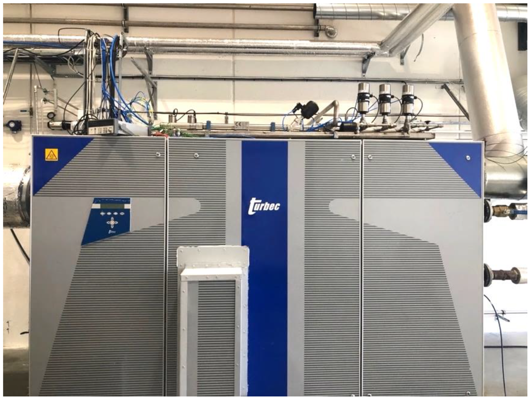
The test rig was based on a commercial Turbec T100 unit (T100PH) Series 2 micro gas turbine. T100PH is a single shaft micro gas turbine designed to work both in power generation mode and in cogeneration mode for combined heat and power generation. The T100 is equipped with a recuperator that preheats the air before the combustion chamber by transferring heat from the turbine exhaust gas. There is also a heat exchanger, exploiting the remaining heat in the exhaust gas to warm up the circulating water.
The power generating unit consists of a single-stage centrifugal compressor, a single-stage radial turbine, a tubular combustor, and a high-speed permanent magnet generator. The compressor and the turbine work with a pressure ratio of about 4.3 and a turbine inlet temperature of around 950 degrees Celsius. At nominal operating conditions (with ISO ambient conditions), the unit can produce 100 kW of electrical power at a rotational speed of 70,000 rpm and electrical efficiency of 30%, thanks to the recuperator which is compensating for the low-pressure ratio and low turbine-inlet temperature. In cogeneration mode, the total efficiency (fuel utilization factor) increases to 80%. The test rig, modified for fuel flexible operation is presented in Figure 2.
During the past few years, numerous modifications have been made to the engine to enable research and development activities, exploring the fuel flexibility of the unit. Recently, the original engine was modified to enable running with hydrogen-enriched fuels, by replacing the original combustor with a new design. The fuel train was also modified to enable different fuel blends in terms of hydrogen content. Over 50 sensors have been installed in different locations of the engine for a comprehensive overview of the engine condition during a test run. In this section, an overview of the main modifications implemented on the engine is provided.
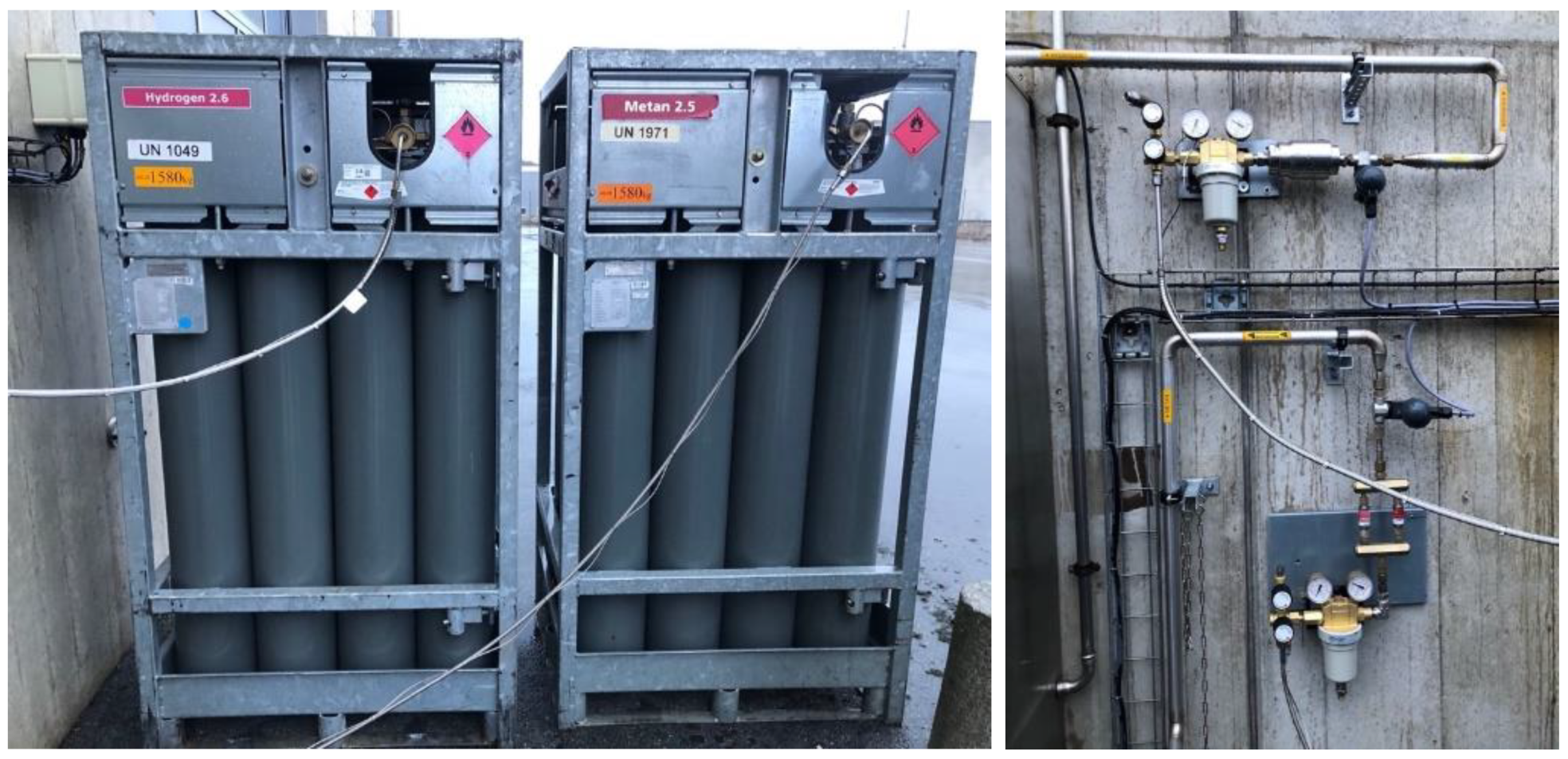
Hydrogen and methane fuel is provided by bundles, each comprising high-pressure interconnected bottles. The bundles are connected to the fuel train via a pressure regulator, to reduce the pressure from over 200 bars to below 20 bars. There are also flashback arrestors and disconnecting valves in the circuit which protect the line. The disconnecting valves are controlled by a leakage sensor inside the building. The bundles and regulator are shown in Figure 3.
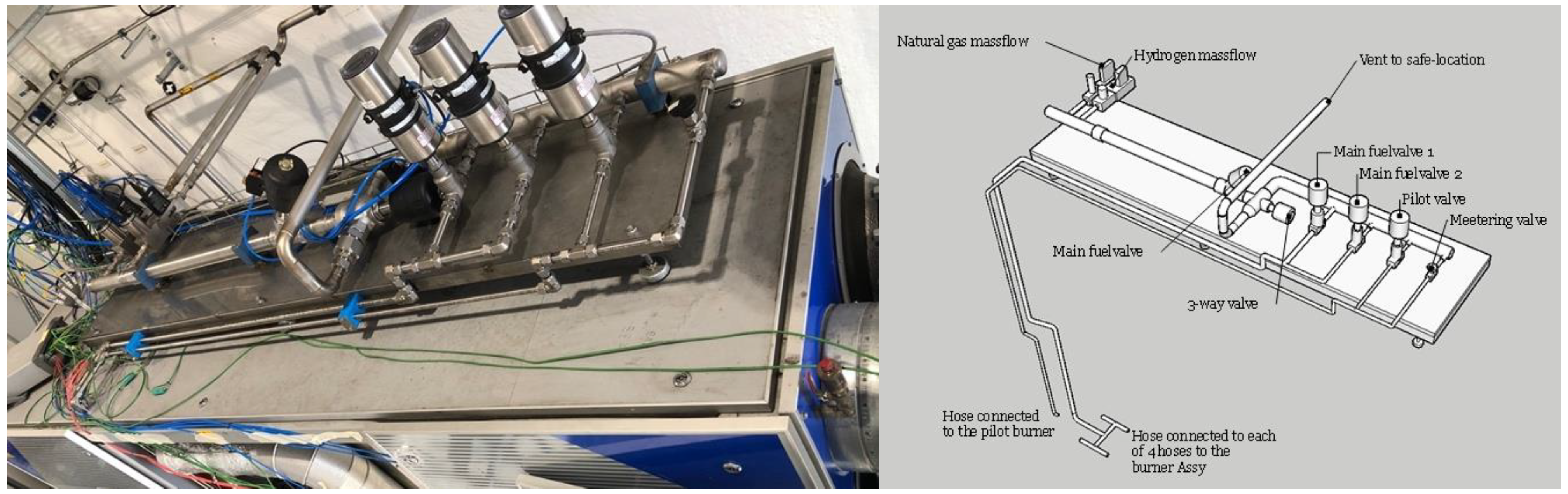
To enable seamless fuel mixing and to accommodate for the changing volume flow of the fuel blend, the fuel train and the gas mixing station have been modified. The system consists of two separate flow controllers for methane and hydrogen, a mixing station, two main valves, and a pilot valve to supply fuel to the MGT. The mixing station is a wide and long pipe that provides enough space so that methane and hydrogen mix well together, preventing hydrogen pockets and local high temperatures inside the combustor which could result in thermal damage and NOx production. The mixed fuel rate is determined by the MGT controller, which has a PID system that finds the adequate fuel flow rate that provides enough heat input to the system at each power set point. The amount of each fuel type is however defined and regulated by the additional controller provided for the fuel train, working based on the ratio of the fuel types defined by the operator.
In Figure 4, the fuel train temporarily installed on top of the MGT encloser is shown with a schematic diagram of the system. Originally, two main valves were installed to increase the flexibility during the operation, however, one of them remained closed since it was not required. A three-way valve that provides discharge to the atmosphere is also included in the system for safety reasons.
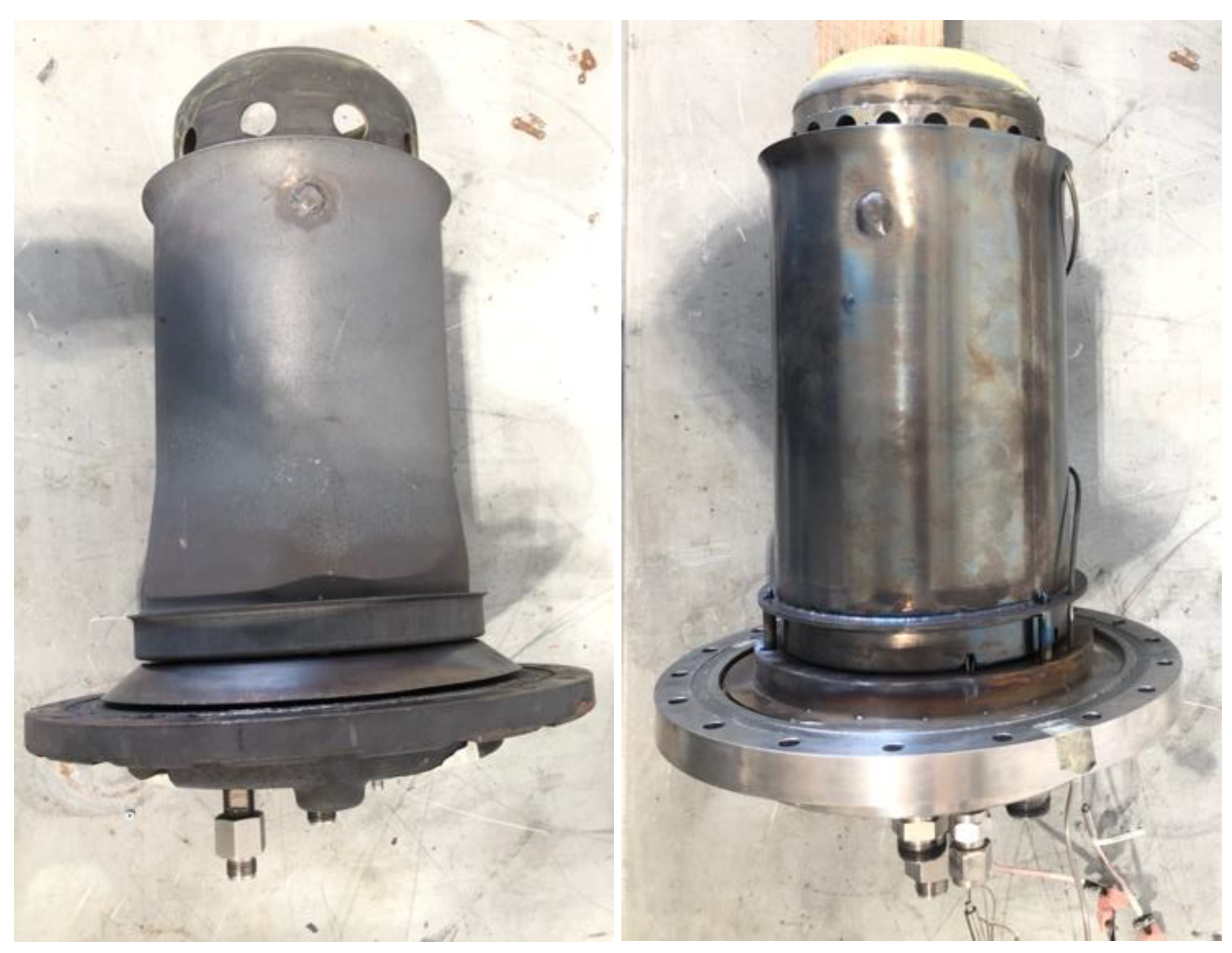
The combustion chamber and fuel system of the MGT test rig have been replaced with a new design to accommodate various fuel mixtures of hydrogen and hydrocarbon-based fuels. The original combustor has been replaced by a fuel-flexible combustor designed and manufactured by the German Aerospace Centre (DLR) to investigate the performance of the engine in different load conditions. To evaluate the unit’s performance and cyclic behavior, additional pressure and temperature sensors have been installed.
The test rig is equipped with an F400s FLOX® combustor (see Figure 5). It is a low NOx, flameless combustor with proven fuel flexibility, capable of running on hydrogen [3,5]. The combustor was tested on an atmospheric test rig with up to 100% hydrogen, but its hydrogen capability in real conditions inside a gas turbine was verified during the current experiments. An overview of the original combustor’s geometry could be found in [34].
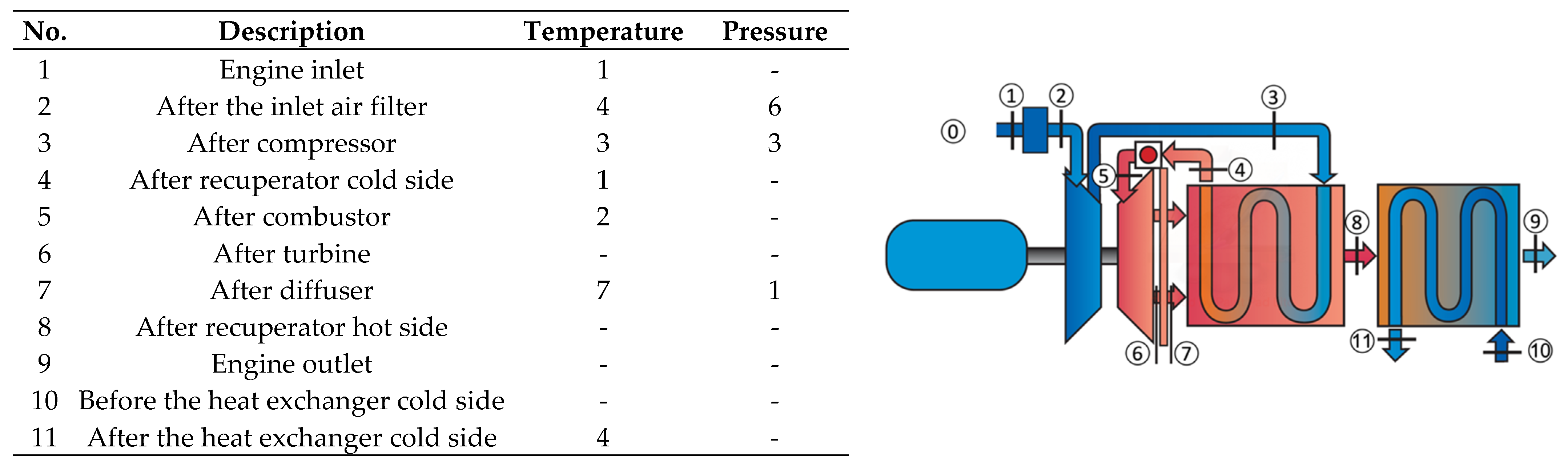
The baseline engine is equipped with sensors, that measure the flow properties, rotational speed, power output, and a few other parameters mainly for controlling the engine operation. The test rig has been equipped with over 50 additional sensors to enable detailed condition monitoring and performance analysis. Figure 6 shows the position of the sensors at different locations. These sensors can be divided into four different categories:
  • Cycle measurements: Pressure and temperature sensors are placed in different locations to provide operational data;
  • Fuel measurement: Pressure, temperature, and mass flow sensors are providing comprehensive information about the fuel at every operational condition;
  • Metal temperature measurement: The metal temperature is measured inside the combustor for lifetime assessments;
  • Emissions measurement: Measuring the concentration of the exhaust gas components.
Among the 32 sensors listed in the table of 
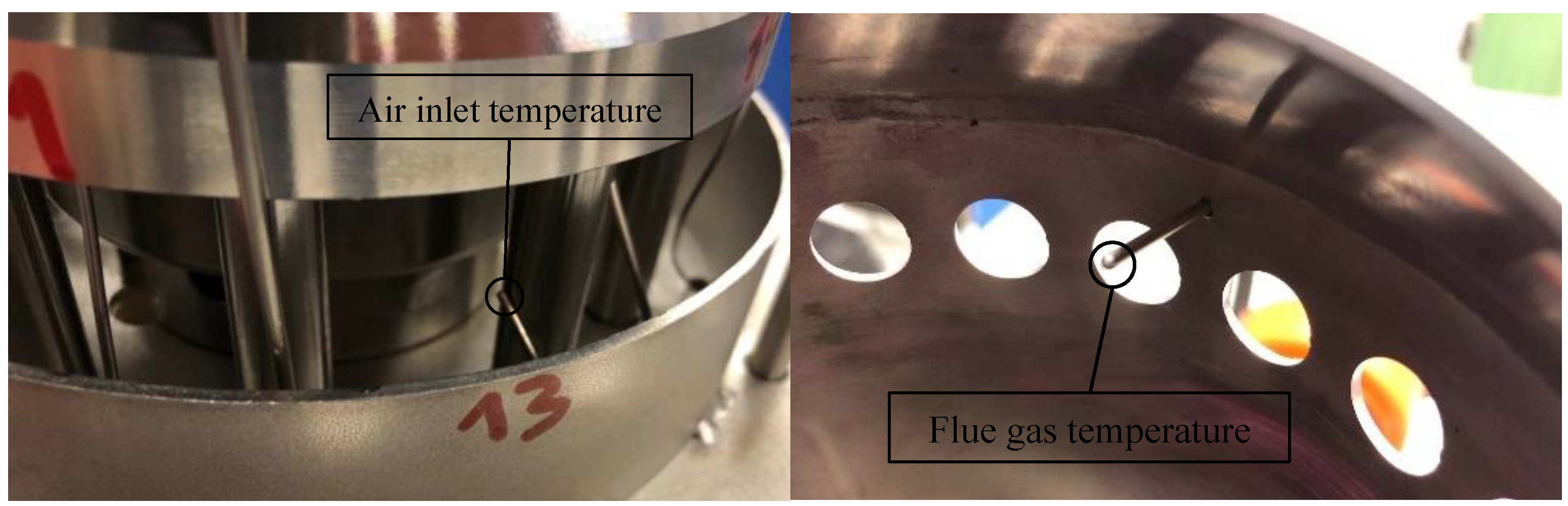
Figure 6 are 6 Turbec built-in sensors and 26 are additionally installed. It is worth mentioning that two thermocouples have been installed in position 5, where the working flow has the highest temperature in the cycle. These sensors are located inside the combustor, measuring the temperature of the flow close to the combustion and dilution zone. The temperature of the inlet air to the combustor is also measured (see Figure 7).
The measurements related to the fuel system are presented in Table 2, providing detailed information about fuel conditions, before and after mixing. The sensors listed in rows 1 to 3 are installed in the fuel train (Figure 3 and Figure 4) and the fuel temperature in the combustor is measured by a thermocouple close to the combustion point.

4. Results

To investigate the transient performance of the engine running with high hydrogen content, a maneuver of the engine with increasing hydrogen content, from 85% to 90% was conducted without changing the controller’s settings. The run was executed in 13 °C ambient temperature and 1.01 bar ambient pressure for which the logged data are presented in Figure 8. Snapshot data are extracted and presented in Table 3, where the performance parameters at each power step in steady-state conditions are presented. The hydrogen content in the fuel is calculated based on the volume flow rate. Power step-up was run with 88% hydrogen and at the maximum load it was increased to 90% and then a step-down was conducted. These data provide the bases for comparison as it was collected from less than an hour’s run, however, the ambient temperature during the run gradually increased by one degree.
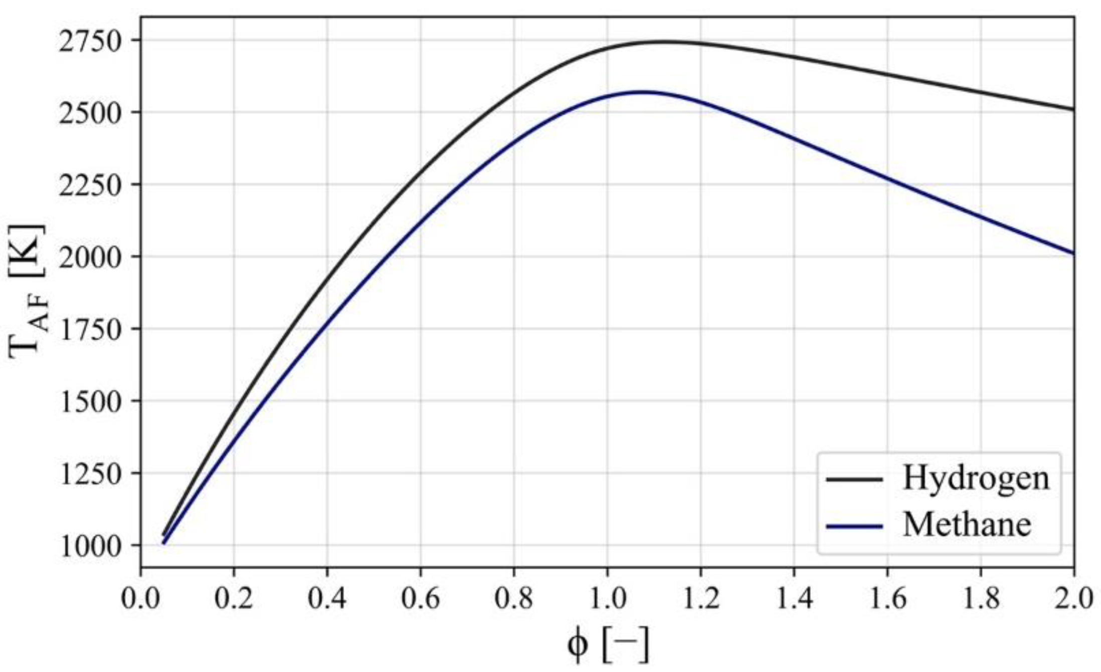
At 100 kW the increase in hydrogen resulted in less than 2 °C increase in flue gas temperature and more than 1 ppm increase in NOx emissions. The same difference in the temperature and emissions could be observed for other power rates as well. The difference in NOx emission rate is due to the higher temperature in the combustor, previously discussed in the section "flame temperature." The variation in combustion temperature is illustrated in Figure 8 and according to the data reported in Table 3, less than 2 °C could be observed in flue gas temperature. This change is measured by the thermocouple shown in Figure 7 which is installed inside the combustor and closed to the dilution holes. Therefore, the measured temperature could only be an indicator of the increase in combustion temperature, since it is a local measurement after cooling and the actual value of the increase in combustion temperature is not clear. Other than the 100 kW case, the comparison for other power rates shows that NOx production is 1 ppm higher due to a 3% increase in hydrogen content.
The rotational speed of the engine for the same power outputs is slightly (less than 1% relative to the nominal speed) higher with increased hydrogen content, however, the ambient temperature is higher during the second half of the operation and that has a direct impact on the rotational speed. In general, when weather is warmer, the engine rotates at higher speeds.
The position of the pilot and main valves is also presented in Figure 8, where the pilot valve position is almost constant throughout the operation. The main valve provides variations in fuel flow rate for the maneuver. The pilot opening for the steady-state operation was originally set to 14%, which is a value appropriate for methane and blended methane/hydrogen fuel with small share of hydrogen. With increasing the amount of hydrogen, the pilot valve is recalibrated to a lower value which keeps the NOx emissions below the regulated amount and also stabilizes the combustion.
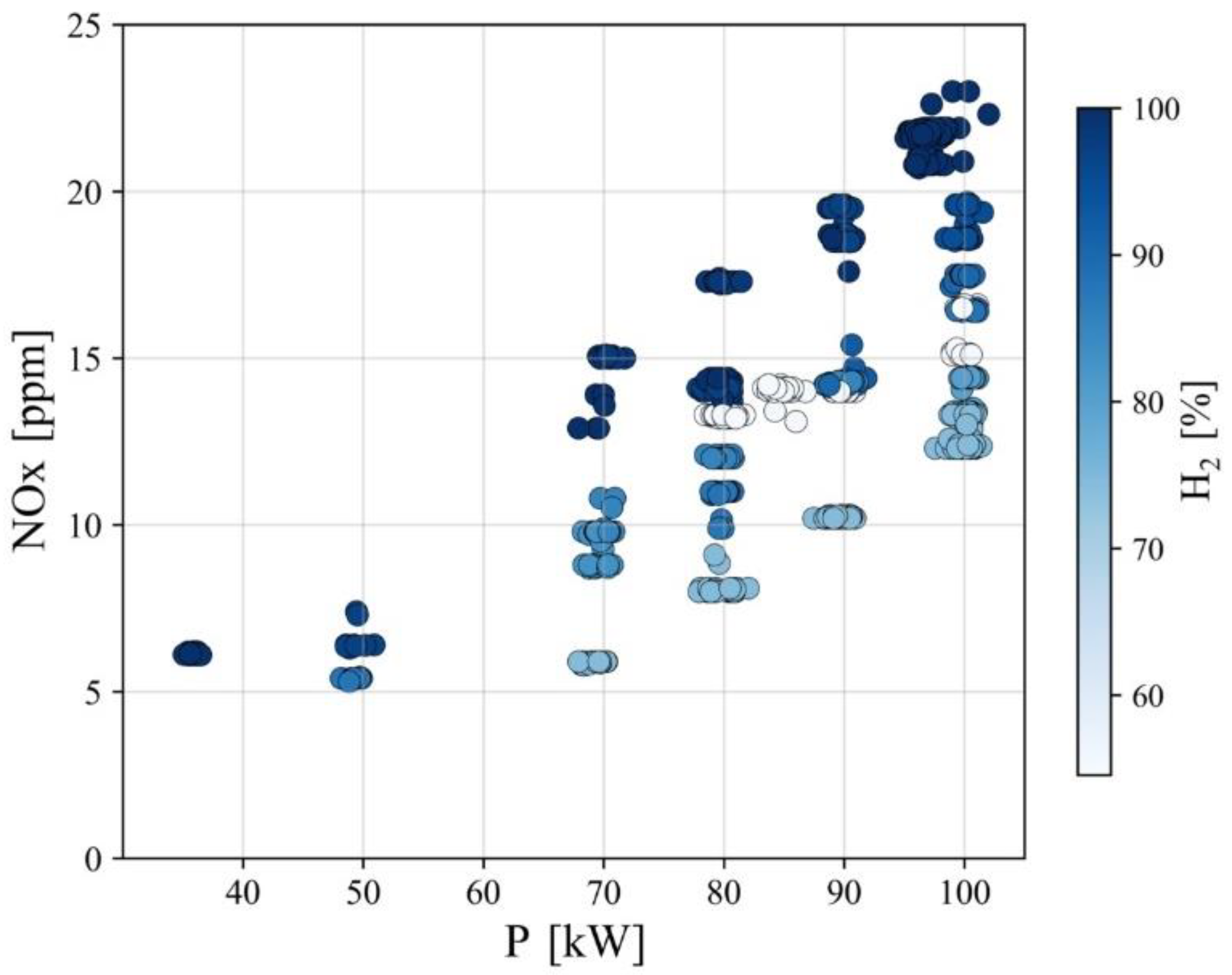
Other than the discussed maneuvers, several runs with different hydrogen content have been conducted. Using the data post-processing tool, the steady-state period data are extracted which can provide insights into the influence of hydrogen injection on the MGT performance parameters. In Figure 9, the NOx emissions in different power outputs with various hydrogen content are presented. The general trend taken from the figure suggests that the production of NOx increases as the share of hydrogen in the fuel increases. There are a few points in Figure 9 that are from the runs with a hydrogen content of around 55% (white circles) which do not follow the general behavior. The reason is that, during that test, the original valve setting was used which led to high NOx emissions. The high temperatures in the combustor encouraged modifying the valves’ settings which led to the lower opening of the pilot valve. All other points are from the maneuvers after recalibration of the valves.
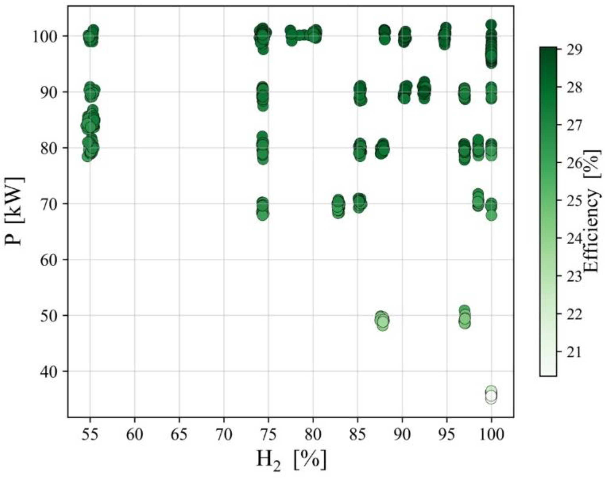
The impact of hydrogen injection on the efficiency of the engine cycle is investigated in Figure 10. The performance of the engine in terms of electrical efficiency for a range of hydrogen contents is similar to each other and increases with the power output. There is a slight difference in the efficiency of the cycle at a constant power output, but the main reason is the effect of ambient conditions; as the engine inlet temperature increases, the efficiency of the engine reduces [35].
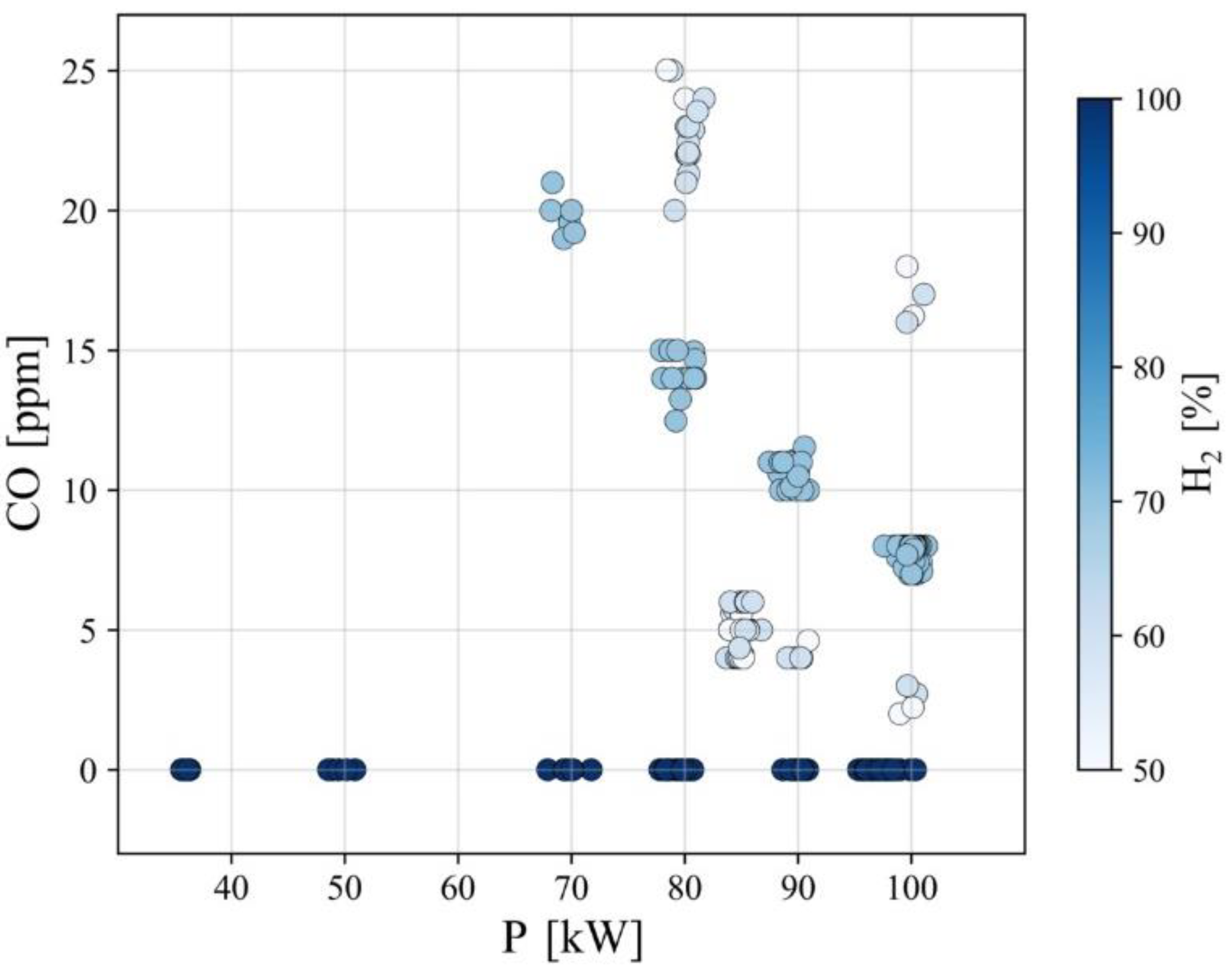
The main reason for replacing carbon-based fuels with hydrogen is to reduce the production of carbon oxides. As discussed, adding hydrogen fuel will contribute to the reduction in the greenhouse gasses that result in global warming, both by replacement of carbon atoms with hydrogen and by promoting combustion efficiency and complete combustion. This effect is illustrated in Figure 11, where a higher content of hydrogen has resulted in lower CO emissions and zero CO emissions are evident for pure hydrogen. The only points that are not compliant with the trends are, once again, the experiment with 55% hydrogen. The run of that case included trials and errors to ensure a stable operation with NOx emissions below the regulated values, so different arrangements for pilot valves were tried. The results of these tests led to different combustion efficiencies and therefore CO emission rates.

5. Conclusions

In this paper, the process of redeveloping a commercial micro gas turbine to operate with blended methane/hydrogen fuel is presented. Previous studies have shown that a small amount of hydrogen injection into gas turbines is tolerated, however, as the share of hydrogen increases, combustion temperatures and therefore NOx emissions increase. Moreover, using the same combustion system will result in unstable combustion and the risk of flashbacks, because of the difference between the combustion characteristics between hydrogen and methane (or natural gas).
During a collaboration between the university of Stavanger and the German Aerospace Centre (DLR), a modified version of the T100 PH micro gas turbine is provided, with minimum modifications required. A new combustor with an innovative design based on FLOX technology developed by DLR is used to accommodate combustion with high hydrogen content. The engine is also equipped with a new fuel train with an additional controller, so a range of fuel blends could be provided for the engine. The modifications to the main controller of the engine are kept to a minimum and confined only to the controller parameters in the software. With a smaller opening in the pilot valve, stable combustion with regulated NOx is realized.
Several maneuvers with different hydrogen contents are conducted for a range of power outputs. The maximum NOx emission is 25 ppm for running the engine at maximum load with pure hydrogen. The corrected NOx emission based on the case with 15% O2 is 64 ppm, which is lower than the regulated value. The electrical efficiency of the engine is not impaired by hydrogen injection into the system. The greenhouse gas emission is reduced by increasing the share of hydrogen in the fuel, by replacement of the carbon element with hydrogen, also by the improvement of combustion efficiency. Close to zero CO emissions are realized when the engine is derived with pure hydrogen.

Author Contributions

Data curation, R.B.; Funding acquisition, M.A.; Software, R.B.; Supervision, M.A.; Visualization, R.B.; Writing—original draft, R.B.; Writing—review and editing, M.A. All authors have read and agreed to the published version of the manuscript.

Funding

This project has received funding from the European Union’s Horizon 2020 research and innovation program under the Marie Skłodowska-Curie grant agreement No. 861079, “NextMGT”- Next Generation of Micro Gas Turbines for High Efficiency, Low Emissions and Fuel Flexibility.

Institutional Review Board Statement

Not applicable.

Informed Consent Statement

Not applicable.

Conflicts of Interest

The authors declare no conflict of interest.

References

  1. European Turbine Network (ETN). Micro Gas Turbine Technology Research and Development for European Collaboration. In ETN Micro Gas Turbine Technology Summary; ETN: Brussels, Belgium, 2018. [Google Scholar]
  2. Pilavachi, P. Mini- and micro-gas turbines for combined heat and power. Appl. Therm. Eng. 2002, 22, 2003–2014. [Google Scholar] [CrossRef]
  3. Lammel, O.; Schütz, H.; Schmitz, G.; Lückerath, R.; Stöhr, M.; Noll, B.; Aigner, M.; Hase, M.; Krebs, W. FLOX® Combustion at High Power Density and High Flame Temperatures. J. Eng. Gas Turbines Power 2010, 132, 121503. [Google Scholar] [CrossRef]
  4. Zornek, T.; Monz, T.; Aigner, M. Performance analysis of the micro gas turbine Turbec T100 with a new FLOX-combustion system for low calorific fuels. Appl. Energy 2015, 159, 276–284. [Google Scholar] [CrossRef] [Green Version]
  5. Lückerath, R.; Meier, W.; Aigner, M. FLOX combustion at high pressure with different fuel compositions. In Proceedings of the ASME Turbo Expo 2007: Power for Land, Sea and Air, Montreal, QC, Canada, 14–17 May 2007; pp. 1–9. [Google Scholar] [CrossRef]
  6. Calabria, R.; Chiariello, F.; Massoli, P.; Reale, F. CFD Analysis of Turbec T100 Combustor at Part Load by Varying Fuels. In Proceedings of the ASME Turbo Expo 2015: Turbine Technical Conference and Exposition, Montreal, QC, Canada, 15–19 June 2015. [Google Scholar]
  7. Langston, L.S. Hydrogen Fueled Gas Turbines. Mech. Eng. 2019, 141, 52–54. [Google Scholar] [CrossRef] [Green Version]
  8. Minakawa, K.; Miyajima, T.; Yuasa, S. Development of a hydrogen-fueled micro gas turbine with a lean premixed combustor. In Proceedings of the 33rd Joint Propulsion Conference and Exhibit, Seattle, WA, USA, 6–9 July 1997; pp. 1–6. [Google Scholar] [CrossRef]
  9. Morris, J.D.; Symonds, R.A.; Ballard, F.L.; Banti, A. Combustion Aspects of Application of Hydrogen and Natural Gas Fuel Mixtures to MS9001E DLN-1 Gas Turbines at Elsta Plant, Terneuzen, The Netherlands. In Proceedings of the ASME International Gas Turbine and Aeroengine Congress and Exhibition, Stockholm, Sweden, 2–5 June 1998. [Google Scholar] [CrossRef] [Green Version]
  10. Shih, H.-Y.; Liu, C.-R. A computational study on the combustion of hydrogen/methane blended fuels for a micro gas turbines. Int. J. Hydrogen Energy 2014, 39, 15103–15115. [Google Scholar] [CrossRef]
  11. Rajpara, P.; Shah, R.; Banerjee, J. Effect of hydrogen addition on combustion and emission characteristics of methane fuelled upward swirl can combustor. Int. J. Hydrogen Energy 2018, 43, 17505–17519. [Google Scholar] [CrossRef]
  12. Cappelletti, A.; Martelli, F. Investigation of a pure hydrogen fueled gas turbine burner. Int. J. Hydrogen Energy 2017, 42, 10513–10523. [Google Scholar] [CrossRef]
  13. Imteyaz, B.A.; Nemitallah, M.; Abdelhafez, A.A.; Habib, M.A. Combustion behavior and stability map of hydrogen-enriched oxy-methane premixed flames in a model gas turbine combustor. Int. J. Hydrogen Energy 2018, 43, 16652–16666. [Google Scholar] [CrossRef]
  14. Horikawa, A.; Okada, K.; Wirsum, M.; Funke, H.H.-W.; Kusterer, K. 100% hydrogen dry low NOx combustor developments for 2MW class gas turbine. In Proceedings of the International Conference on Power Engineering (ICOPE), Yokohama, Japan, 17–21 October 2021; Volume 2021. [Google Scholar] [CrossRef]
  15. Funke, H.H.-W.; Beckmann, N.; Keinz, J.; Horikawa, A. 30 Years of Dry-Low-NOx Micromix Combustor Research for Hydrogen-Rich Fuels—An Overview of Past and Present Activities. J. Eng. Gas Turbines Power 2021, 143. [Google Scholar] [CrossRef]
  16. Sun, Y.; Zhang, Y.; Huang, M.; Li, Q.; Wang, W.; Zhao, D.; Cheng, S.; Deng, H.; Du, J.; Song, Y.; et al. Effect of hydrogen addition on the combustion and emission characteristics of methane under gas turbine relevant operating condition. Fuel 2022, 324, 124707. [Google Scholar] [CrossRef]
  17. Anderson, D.N. Effect of Hydrogen Injection on Stability and Emissions of an Experimental Premixed Prevaporized Propane Burner; Report NASA TMX-3301; Lewis Research Center, National Aeronautics and Space Administration: Cleveland, OH, USA, October 1975.
  18. Emami, S.D.; Kasmani, R.M.; Hamid, M.D.; Hassan, C.R.C.; Mokhtar, K.M. Kinetic and dynamic analysis of hydrogen-enrichment mixtures in combustor systems—A review paper. Renew. Sustain. Energy Rev. 2016, 62, 1072–1082. [Google Scholar] [CrossRef]
  19. Wei, Z.; He, Z.; Zhen, H.; Zhang, X.; Chen, Z.; Huang, Z. Kinetic modeling investigation on the coupling effects of H2 and CO2 addition on the laminar flame speed of hydrogen enriched biogas mixture. Int. J. Hydrogen Energy 2020, 45, 27891–27903. [Google Scholar] [CrossRef]
  20. He, Y.; Liang, M.; Liu, C.; Liao, S.; Yang, R.; Qin, L.; Jian, X.; Shao, Y. Kinetic incentive of hydrogen addition on nonpremixed laminar methane/air flames. Int. J. Hydrogen Energy 2021, 46, 14813–14823. [Google Scholar] [CrossRef]
  21. Wu, J.; Brown, P.; Diakunchak, I.; Gulati, A.; Lenze, M.; Koestlin, B. Advanced Gas Turbine Combustion System Development for High Hydrogen Fuels. In Proceedings of the ASME Turbo Expo: Power for Land, Sea, and Air, Montreal, QC, Canada, 14–17 May 2007; Volume 2, pp. 1085–1091. [Google Scholar] [CrossRef] [Green Version]
  22. Zhou, Q.; Cheung, C.; Leung, C.; Li, X.; Li, X.; Huang, Z. Effects of fuel composition and initial pressure on laminar flame speed of H2/CO/CH4 bio-syngas. Fuel 2018, 238, 149–158. [Google Scholar] [CrossRef]
  23. Amar, H.; Abdelbaki, M.; Fouzi, T.; Zeroual, A. Effect of the addition of H 2 and H 2 O on the polluting species in a counter-flow diffusion flame of biogas in flameless regime. Int. J. Hydrogen Energy 2018, 43, 3475–3481. [Google Scholar] [CrossRef]
  24. Xiang, L.; Jiang, H.; Ren, F.; Chu, H.; Wang, P. Numerical study of the physical and chemical effects of hydrogen addition on laminar premixed combustion characteristics of methane and ethane. Int. J. Hydrogen Energy 2019, 45, 20501–20514. [Google Scholar] [CrossRef]
  25. Toof, J.L. A Model for the Prediction of Thermal, Prompt, and Fuel NOx Emissions from Combustion Turbines. J. Eng. Gas Turbines Power 1986, 108, 340–347. [Google Scholar] [CrossRef]
  26. Cowell, L.H.; Smith, K.O. Development of a Liquid-Fueled, Lean-Premixed Gas Turbine Combustor. J. Eng. Gas Turbines Power 1993, 115, 554–562. [Google Scholar] [CrossRef]
  27. Ditaranto, M.; Heggset, T.; Berstad, D. Concept of hydrogen fired gas turbine cycle with exhaust gas recirculation: Assessment of process performance. Energy 2020, 192, 116646. [Google Scholar] [CrossRef]
  28. Venkataraman, K.K.; Preston, L.H.; Simons, D.W.; Lee, B.J.; Lee, J.G.; Santavicca, D.A. Mechanism of Combustion Instability in a Lean Premixed Dump Combustor. J. Propuls. Power 2012, 15, 909–918. [Google Scholar] [CrossRef]
  29. Lee, I.B.; Woo, I.S.; Lee, M.C. Effects of nitrogen dilution on the NOx and CO emission of H2/CO/CH4 syngases in a partially-premixed gas turbine model combustor. Int. J. Hydrogen Energy 2016, 41, 15841–15851. [Google Scholar] [CrossRef]
  30. Schefer, R.W. Reduced Turbine Emissions Using Hydrogen-Enriched Fuels. In Proceedings of the 2002 US DOE Hydrogen Program Review, NREL/CP-610-32405, Golden, CO, USA, 6–10 May 2002. [Google Scholar]
  31. Juste, G.L. Hydrogen injection as additional fuel in gas turbine combustor. Evaluation of effects. Int. J. Hydrogen Energy 2006, 31, 2112–2121. [Google Scholar] [CrossRef]
  32. Tang, C.; Zhang, Y.; Huang, Z. Progress in combustion investigations of hydrogen enriched hydrocarbons. Renew. Sustain. Energy Rev. 2014, 30, 195–216. [Google Scholar] [CrossRef]
  33. Chiesa, P.; Lozza, G.; Mazzocchi, L. Using Hydrogen as Gas Turbine Fuel. J. Eng. Gas Turbines Power 2005, 127, 73–80. [Google Scholar] [CrossRef]
  34. Cadorin, M.; Pinelli, M.; Vaccari, A.; Calabria, R.; Chiariello, F.; Massoli, P.; Bianchi, E.C. Analysis of a Micro Gas Turbine Fed by Natural Gas and Synthesis Gas: MGT Test Bench and Combustor CFD Analysis. J. Eng. Gas Turbines Power 2012, 134, 071401. [Google Scholar] [CrossRef]
  35. Technical Description Microturbine Turbec T100. Available online: www.ensola.com (accessed on 5 October 2022).
Figure 1. Adiabatic flame temperature for burning methane and hydrogen.
Sustainability 14 13305 g001
Figure 2. Turbec T100 unit with modified combustor and fuel train for flexible fuel operation.
Sustainability 14 13305 g002
Figure 3. Fuel bundles and regulators.
Sustainability 14 13305 g003
Figure 4. Fuel train for hydrogen/methane fuel supply and mixing.
Sustainability 14 13305 g004
Figure 5. The original combustor was installed on T100 (left) compared to the F400s fuel flexible combustor installed on the test rig (right).
Sustainability 14 13305 g005
Figure 6. Cycle measurements.
Sustainability 14 13305 g006
Figure 7. Flow measurements installed in the combustor.
Sustainability 14 13305 g007
Figure 8. Power variation with F400-s ver02, modified controller setup. The ambient condition during the test is 13 °C and 1.01 bar.
Sustainability 14 13305 g008
Figure 9. NOx production in a range of power outputs with respect to hydrogen content in the fuel.
Sustainability 14 13305 g009
Figure 10. Electrical efficiency of the engine in a range of power output and hydrogen content in the fuel.
Sustainability 14 13305 g010
Figure 11. CO emission in a range of power output with different hydrogen content in the fuel.
Sustainability 14 13305 g011
Table 1. Flue gas properties comparison burning methane and hydrogen. Air composition is 21% O2 and 79% N2 with 4.3 bar pressure and 610 K temperature.
PropertyMethaneHydrogen
Lower heating value (per mass) 50   MJ / kg 120   MJ / kg
Fuel flow rate for nominal power output 6.7   g / s 2.8   g / s
Air flow rate 0.8   kg / s 0.8   kg / s
Flue gas flow rate 0.67   m 3 / s 0.68   m 3 / s
Stoichiometric air–fuel ratio (mass-based) 17.12 34.06
Actual air–fuel ratio (mass-based) 120 288
Equivalence ratio 0.14 0.12
Adiabatic flame temperature 1230.52   K 1236.51   K
Flue gas heat capacity at constant pressure 1214.8   J / kgK 1228.8   J / kgK
Table 2. Number of fuel measurements in the fuel system.
DescriptionTemperaturePressureMass flowrate
Methane fuel111
Hydrogen fuel111
Mixed fuel11-
Fuel in combustor1--
Table 3. Data extracted from steady-state spans from a test run depicted in Figure 8.
Elapsed time P   ( kW ) N   ( % ) m ˙ f ( g / s ) H 2   ( % ) T comb ( ° C ) NOx   ( ppm ) V pilot   ( % ) V main ( % )
t 1 1003577.92.185.1869.83.310.320.6
t 2 6005082.92.487.7899.75.410.525.1
t 3 8507089.53.187.6934.58.79.831.5
t 4 10008092.73.587.7948.111.010.335.0
t 5 13509095.83.988.1966.313.910.639.5
t 6 160010098.74.287.9979.216.49.943.3
t 7 180010098.84.190.4980.517.510.243.9
t 8 21009096.03.790.4964.614.210.239.2
t 9 23508093.53.390.3947.812.010.235.8
t 10 25007090.22.990.3933.59.710.231.3
t 11 28005083.72.390.0902.65.39.924.9
Publisher’s Note: MDPI stays neutral with regard to jurisdictional claims in published maps and institutional affiliations.

