Article

Feasibility of Applying Mel-Frequency Cepstral Coefficients in a Drive-by Damage Detection Methodology for High-Speed Railway Bridges

by
Edson Florentino de Souza
1,2,*,
Túlio Nogueira Bittencourt
2,
Diogo Ribeiro
3 and
Hermes Carvalho
4
1
Department of Civil Engineering (COECI), Federal University of Technology—Parana (UTFPR), Guarapuava 85053-525, Brazil
2
Department of Structural Engineering and Geotechnical (PEF), University of São Paulo (USP), São Paulo 05508-900, Brazil
3
Institute of R&D in Structures and Construction (CONSTRUCT), School of Engineering, Polytechnic of Porto, 4200-072 Porto, Portugal
4
Department of Structural Engineering, Federal University of Minas Gerais (UFMG), Belo Horizonte 31270-901, Brazil
*
Author to whom correspondence should be addressed.
Sustainability 2022, 14(20), 13290; https://doi.org/10.3390/su142013290
Submission received: 13 August 2022 / Revised: 8 October 2022 / Accepted: 11 October 2022 / Published: 16 October 2022
(This article belongs to the Special Issue Sustainable Railway Infrastructure and Rolling Stock)

Abstract

:
In this paper, a drive-by damage detection methodology for high-speed railway (HSR) bridges is addressed, to appraise the application of Mel-frequency cepstral coefficients (MFCC) to extract the Damage Index (DI). A finite element (FEM) 2D VTBI model that incorporates the train, ballasted track and bridge behavior is presented. The formulation includes track irregularities and a damaged condition induced in a specified structure region. The feasibility of applying cepstrum analysis components to the indirect damage detection in HSR by on-board sensors is evaluated by numerical simulations, in which dynamic analyses are performed through a code implemented in MATLAB. Different damage scenarios are simulated, as well as external excitations such as measurement noises and different levels of track irregularities. The results show that MFCC-based DI are highly sensitive regarding damage detection, and robust to the noise. Bridge stiffness can be recognized satisfactorily at high speeds and under different levels of track irregularities. Moreover, the magnitude of DI extracted from MFCC is related to the relative severity of the damage. The results presented in this study should be seen as a first attempt to link cepstrum-based features in an HSR drive-by damage detection approach.

1. Introduction

With the continuous development of new HSR lines around the globe, bridges account for a large proportion of these infrastructures and, as a result, the demand for condition assessment of such a great number of bridges is steadily increasing [1,2,3]. In recent decades, vibration-based Structural Health Monitoring (SHM) has been extensively explored as one of the most common assessment methodologies. Indeed, SHM has been an active field of research for over three decades. In conventional approaches (direct SHM), the dynamic responses of structures are typically evaluated using sensors installed directly on the bridge. However, these types of monitoring are time-consuming and laborious in deploying sensors and equipment, which are often planned on a one-system-per-bridge basis [4,5].
For this reason, indirect approaches for SHM of bridges have garnered increased interest, particularly as an efficient and comprehensive method of inspecting many railway bridges with a single run. The main approach used consists in the drive-by estimation of passing railway bridges based on the on-board measured data of an in-service train traveling on the specific routes [6,7]. Based on VBI, these approaches analyze the vibration signals of a moving vehicle, using embedded sensors. The idea of these systems is that a moving vehicle crossing a bridge can function as a mobile exciter and sensor. Because of the dynamic interaction between the passing vehicle and the vibrating bridge, the vehicle’s response contains bridge-related information and can be used for bridge health evaluation. Not only do indirect SHM frameworks require no instrumentation on the bridge, but they also give a greater spatial resolution monitoring system, as the response of the passing vehicle and the bridge is measured at multiple contact points along the bridge [8].
Drive-by bridge evaluation has been proposed for cost-effective SHM, and numerous research on bridge performance evaluation and damage detection using this method have been conducted in the highway field. However, there are not enough studies on procedures for drive-by bridge inspection on HSR [9]. The feasibility of estimating bridge conditions by extracting their natural frequencies using moving vehicles was introduced and described theoretically and experimentally by [10,11]. Afterward, the parameters that influence the drive-by evaluation of bridges were discussed [12], and a filtering approach was proposed for this drive-by extraction method [13]. In addition to these pioneering efforts, the estimation of bridge vibration using the drive-by system has been researched worldwide, with a focus on scaled-down model experiments [14,15,16,17]. Moreover, further investigations on drive-by bridge evaluation (referred to as vehicle scanning) and its applications to highway bridges and railway tracks have recently been conducted [18].
In recent years, a variety of drive-by bridge inspection methods have been proposed, such as those employing particle filters [19], data-driven neural networks [20], frequency-independent underdamped pinning stochastic resonance [21], the bridge displacement profile [22], the bridge frequency with two vehicles [23] and a data-driven approach [8]. In most of these investigations in SHM, the fundamental frequency of the bridge was discovered indirectly via a frequency domain analysis of the mixed bridge responses of vehicles, which has been limited to relatively slow-moving vehicles that remain on the bridges for an extended period, due to limited frequency resolution and bridge–vehicle interactions [24]. At high vehicle speeds, the frequency resolution of the on-vehicle measured data and the transmission of the bridge reaction to the car via bridge–vehicle interactions are significantly undermined [6]. In like manner, to identifying bridge frequencies, other parameters of the bridge such as bridge modal shapes, bridge damping [25,26,27,28], and bridge damage can also be identified from vehicle responses. A comprehensive analysis of the most recent development of the drive-by bridge assessment is presented in [29], with its applications categorized according to the following aspects: modal identification, damage detection, pavement roughness detection, attempts by or including modern devices, identification of vehicle properties and railway track detection.
Regarding bridge damage detection as a relevant application of the drive-by bridge inspection method [30,31,32,33], based on the identified modal parameters, the structural damage of the bridge under different conditions can be detected [6,34,35,36,37]. For damage detection of railway tracks, a theoretical framework for a two-axle test vehicle traveling over train lines was proposed by [38]. The driving component of the contact-point response was processed by the Hilbert transform to take the instantaneous amplitude squared (IAS), which was identified as a good damage indicator, yet the damaged region cannot be excited appropriately at higher vehicle speeds.
An overview of recent progress in vibration-based damage identification methods and theoretical development of damage detection strategies for bridge structures is provided by [39], including intelligent algorithms, the Bayesian theory, and time-domain signal processing–based methodologies. Structural damage detection and SHM methods can be categorized as modal-based [40] or signal-based [41]. Modal-based approaches employ alterations in measured modal parameters or their derivatives, to determine structural deterioration. Signal-based approaches rely on vibration measurements, which are indicative of structural damage. These methods use adequate signal processing techniques to detect damage by tracking alterations in the features generated directly from the recorded dynamic responses or their associated spectra. Principal vibration signal processing techniques are based on time and frequency analysis, time-frequency analysis, and cepstral analysis [41,42]. Indirect damage detection was also studied, by utilizing mature technologies to process the vehicle responses, such as wavelet transform [30], frequency response function [43], and machine learning approach [44,45,46,47,48], among others. Deep learning algorithms have also been applied to the prediction of time-history responses of the bridge under vehicular loads with few and measurable input features extracted from VBI systems and vehicle responses to produce reliable training data [49].
Recent research has focused on the novel idea of cepstrum-based operational modal analysis [42,50,51,52,53,54]. Cepstrum analysis provides information from the vibration signal as a function of quefrency, and appears to be effective for identifying subtle spectrum changes. Initial studies of cepstrum-based analysis have demonstrated the method’s great potential for SHM applications [55]. Nevertheless, in this field, there are few recent research papers on employing cepstrum for damage detection, and they all involve non-destructive evaluation or direct SHM. Cepstral distance has been used to extract features for damage detection in layered carbon fiber reinforced polymer [56] and to generate frequency response functions using response-only measurements, where the difference between baseline and damaged frequency response functions was then used to compress the data and to train neural networks for damage-detection [52].
Mel-frequency cepstrum (MFC) is a type of cepstrum analysis that has also drawn the attention of SHM researchers. In contrast with the performance of conventional delamination detection methods, which are easily impacted by environmental noise and the subjectivity of the inspector, independent component analysis and MFCC were associated with a radial basis function network for delamination detection, and experiments and field tests have demonstrated the robustness of the technique to noise, even with insufficient training data [57]. Damage identification based on auto-regressive coefficients was also undertaken as a point of comparison with adapting MFCC, and their Mahalanobis distance used as damage features in a computational 10 degrees of freedom (DOFs) and on a nonlinearly behaving laboratory structure. The method based on MFCC presented better results than the one based on auto-regressive coefficients [58]. MFCC were also adopted as features in a vibration-based SHM methodology proposed to assess the health conditions of monitored civil structures by drawing knowledge from rich classification models trained on large datasets, such as audio sets (the source domain) commonly used for speech and speaker recognition purposes [59,60,61].
Despite being a research subject that has recently aroused interest in the SHM area, there are still only a small number of works applying MFCC to indirect health monitoring for damage detection. Indeed, to the best of the authors’ knowledge, only two studies have addressed this topic. Firstly, a novel damage feature extracted from adapted MFCC was proposed for damage detection of bridges using drive-by data, focusing on the highway SHM field and the concept of using mobile sensor network [62]. The numerical analysis and laboratory experiment results showed that the approach could identify the existence of damage and provide useful information about its severity. Subsequently, the aforementioned adapted MFCC was applied to a drive-by damage detection framework [63]. The method’s feasibility was verified numerically with a single DOFs sprung mass model and by a laboratory experiment.
In this paper, a drive-by damage detection methodology for HSR bridges is addressed to appraise the application of MFCC to extract features that are related to bridge damage. The organization of the article is as follows: firstly, a 2D VTBI model that incorporates the train, ballasted track and bridge behavior is presented, in which the train cars consist of four-axle vehicles, the track is modeled as a beam resting on uniformly distributed spring-mass systems, and the bridge deck of the HSR is modeled as a simply supported Bernoulli-Euler beam. The formulation includes track irregularities and damage conditions induced in a specified structure region. Secondly, the proposed drive-by damage detection strategy is demonstrated, and the premises of the damage index extraction from the MFCC approach are discussed. Afterward, the feasibility of applying cepstrum analysis components to the indirect damage detection in HSR by on-board sensors is evaluated by numerical simulations, in which dynamic analyses are performed through a code implemented in MATLAB® [64]. Different damage scenarios are simulated, as well as external excitations such as measurement noises and different levels of track irregularities. Finally, the key results are summarized in the last section, and some prospects are highlighted. The results presented in this study should be seen as a first attempt to link cepstrum-based features in an HSR drive-by damage detection approach.

2. Methodology

2.1. Vehicle-Track-Bridge Dynamic Interaction System

The passing trains induce severe vibrations in the substructures, which may affect the proper operation of the track and bridge structures. In turn, the track and bridge’s sharply dynamic behaviors can influence the trains’ dynamic performance. In order to evaluate the dynamic performance and service life of the train–track–bridge system, it is necessary to take the train, the track, and the bridge as a coupled system into account and analyze them simultaneously [65].
In general, in train–bridge dynamic interaction models, the bridge subsystem is usually modeled on the finite element method (FEM) or continuous beam theories, whereas the theory of multi-body system dynamics is adopted to establish the moving vehicle subsystem, which implies that most of the vehicle degrees of freedom, or equations of motion, are assigned to the motions of the vehicle bodies [66,67]. A comprehensive literature review of railway vehicle modeling is provided in [67], and a substantial state-of-the-art review of train–track–bridge dynamic interaction is presented in [65].
This section describes the 2-dimensional VTBI model used in the present study to numerically simulate a high-speed train response to a bridge-crossing event. Plane VBI systems can satisfactorily predict vertical dynamic response [68,69]. As to ballasted railways tracks consisting of rails, pads, sleepers, ballast, and sub-ballast, it is possible to depict the track with varying degrees of complexity, which may be roughly categorized by the number of sprung layers taken into account [70].

2.1.1. Vehicle Model

The multi-rigid-body vehicle model considered is schematically depicted in Figure 1a. It is assumed that the train is composed of N c independent vehicles and crosses the bridge at a constant speed v . Each vehicle has one carbody, two bogies, and four wheelsets. The carbody frame has been modeled as a rigid body with a concentrated mass m c and rotary inertia J c . Similarly, each bogie frame has also been modeled as a rigid body and has a concentrated mass m b and a rotary inertia J b . The carbody and bogie frame rotary inertias are about the transverse horizontal axis through its center of gravity. The wheelsets are represented as lumped masses m w that are connected to the bogie frames by means of spring-dashpot sets representing the primary suspension with spring stiffness k 1 y and damping coefficient c 1 y . Bogie frames are coupled to the carbody by spring-dashpot sets with spring stiffness k 2 y and damping coefficient c 2 y , representing the secondary suspension system.
In total, the vehicle model has ten independent DOFs that correspond to seven vertical displacements for the masses ( y c ,   y b 1 ,   y b 2 ,   y w 1 ,   y w 2 ,   y w 3 , and y w 4 ), and three rotations of the rigid bars ( θ c ,   θ b 1 , and θ b 2 ). This model has been extensively discussed in the literature, and its equations of motion may be found in a variety of sources [70,71].

2.1.2. Track Model

As depicted in Figure 1b, the track is modeled as a beam resting on uniformly distributed spring-mass systems. The rail is modeled specifically as an Euler–Bernoulli beam using FEM discretization, whose behavior is characterized by four parameters: Young’s modulus E r , sectional area A r , moment of inertia I r , and mass per unit length a mass per unit length of m ¯ r . The sleepers are represented as masses M s separated by a regular spacing L s and coupled to the rail by a spring-dashpot system with stiffness K p and viscous damping C p representing the pad. The ballast is depicted as a lumped mass M b a that interacts with the sleeper via a spring-dashpot layer with stiffness K b a and a damping coefficient C b a . The third layer represents the dynamic qualities of the sub-ballast, using an additional spring-dashpot system in parallel with stiffness K s b and viscous damping C s b , respectively. The rail irregularities r x at the x -coordinate are taken into account by introducing random irregularity profile functions on the rail surface, which describe the deviation from a perfectly smooth track. The track irregularities are measured relative to the beam’s vertical static equilibrium locations (mean horizontal axle).

2.1.3. Bridge Model

The bridge deck of the HSR is modeled as a simply supported Bernoulli-Euler beam (Figure 1c) with a mass per unit length of m ¯ , Young’s modulus E b , sectional area A b , moment of inertia I b and equivalent damping coefficient c . The bridge is implemented utilizing FEM formulation with beam elements. Numerous papers have detailed the elemental matrices [70,72], and the assembly of these matrices into global form yields the set of motion equations that characterize the dynamic behavior of the bridge. In order to simulate the structure damage being identified and localized indirectly by the passing vehicle, a beam region has its bending stiffness affected by a coefficient f s r (reduction stiffness ratio).

2.1.4. Equations of Motion for the VTBI System

All the above-mentioned subsystems are incorporated into a single VTBI model. The train convoy is composed of c = 1 ,   2 , , N c independent cars traveling in succession. The vehicles travel on a rail supported by three layers of spring-dashpot systems representing the pad, ballast, and sub-ballast. The track is then supported by either the bridge or a rigid foundation (Figure 1b). The length of the track is adequate to prevent the vehicle from reaching the bridge until it has reached dynamic equilibrium. It is also sufficiently long for the vehicle to completely exit the bridge [70].
A set of motion equations specifies each subsystem. These second-order differential equations can be expressed in a general matrix form, using the mass, damping, and stiffness time-dependent global matrices— M , C , and K , respectively—together with the vector of external forces F and solved for the vector X of the global displacements (DOFs). The coupled equations of motion of the model as a whole can be represented in a sub-matrices form as
M V 0 0 0 M T 0 0 0 M B X ¨ V X ¨ T X ¨ B + C V C VT 0 C TV C T C TB 0 C BT C B X ˙ V X ˙ T X ˙ B + K V K VT 0 K TV K T K TB 0 K BT K B X V X T X B = F V F T F B
where the subscripts V , T , and B the vehicle, track, and bridge subsystems, respectively. In Equation (1), the coupling of the subsystems is mathematically described with additional off-diagonal block matrices. These coupling terms are determined by the beam element’s shape function and the mechanical parameters of the system. A complete derivation of these mathematical expressions is presented by [73] in greater detail.
The coupling terms between the vehicle and the track depend on the vehicle’s position; hence, they are time-dependent and must be computed at each time step. Conversely, the coupling terms between the track and bridge stay unchanged, since their configuration does not vary within a single simulation. It should be noted that when the vehicle and track are connected, some of the vehicle’s DOFs are combined with those of the track. Consequently, the mass matrix of the track M T must be modified at each time step, to account for the increased masses of the wheels [70,71,72,73].

2.2. Irregularity of Track Vertical Profile

In general, with the exception of areas with turnouts, road crossings, and deteriorating rail lines, the irregularities of the track’s vertical profile can be viewed as stationary ergodic Gaussian random processes in a space domain along the track’s length, which is characterized by a superposition of random harmonic waves with varying wavelengths, phases, and amplitudes [74]. Power spectral density (PSD) is the most significant and widely employed statistical function for simulating random track irregularities. PSD of track irregularities are curves of constant variation, in which spectral density is the ordinate and either frequency or wavelength is the abscissa, in which the relationship between irregularity amplitude and frequency is clearly evidenced [72].
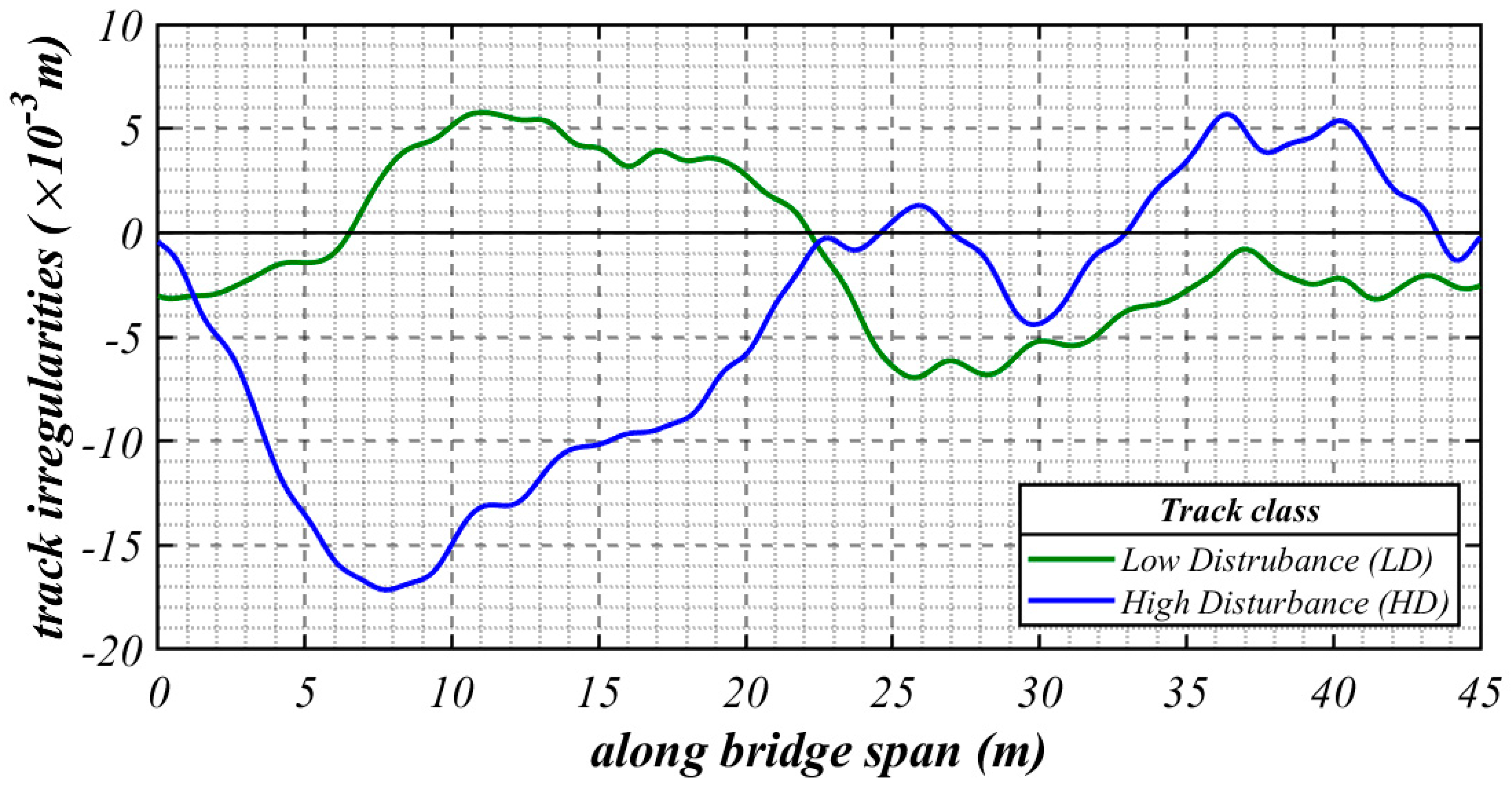
For the numerical simulations presented in Section 3, two vertical track profiles with random vertical irregularities were generated using a random function r x of zero expectance and constant variance presented by [75], and expressed by a trigonometry series as
r ( x ) = 2 j = 1 N S Ω j Δ Ω cos Ω j x + ϕ j ,
where ϕ j is a random phase with uniformity distribution in 0 ,   2 π   r a d , S Ω j is the PSD function evaluated in the j th spatial frequency Ω j r a d / m of the discrete domain Ω j = Ω l + j 1 / 2 Δ Ω , with j = 1 , 2 , , N , and whose frequency band Δ Ω = Ω c Ω r / N is defined by the lower and upper limit’s spatial frequencies, respectively Ω l = 2 π / L r , m a x and Ω u = 2 π / L r , m i n , and by the wavelength range L r , m i n ,   L r , m a x in which the PSD function is included.
For Equation (2), the following were assumed: N = 3540 (number of spatial frequencies), L r , m i n = 1.524   m , L r , m a x = 304.8   m , and the German PSD function has been used, which is written by
S V Ω = A V Ω c 2 Ω 2 + Ω r 2 Ω 2 + Ω c 2 m 2 r a d / m ,
where Ω c and Ω r are the cut-off frequencies and A V is the roughness constant, whose values are presented in Table 1. Figure 2 shows the irregularity profiles used in the numerical simulations.

2.3. Drive-by Damage Detection Using MFCC

The main goal of feature extraction is to turn the unprocessed input signal into a representation with minimal variables, which contains the most discriminating information and which can adequately reduce the input’s dimensionality and eliminate redundant or irrelevant information, in order to produce the series of feature vectors. With this intention, cepstral analysis is frequently used to derive MFCC features from raw data [42]. The MFCC represents a signal’s short-term power spectrum, using a linear cosine transform of a log power spectrum on a nonlinear Mel frequency scale [76].
Cepstrum analysis scans and extracts information for a range of frequencies instead of merely looking for peaks, and assigns equal weights to different frequency ranges. In contrast, MFC analysis assigns more weights to lower frequency, which is crucial for bridge monitoring. MFC is originally designed to mimic how human beings respond with their auditory system, for which the conceptual distance between 100 Hz and 200 Hz is substantially more meaningful than the same linear distance between 10,000 Hz and 10,100 Hz. The scenario is comparable to the bridge’s frequency domain, where the lower frequency range containing the most significant modes is usually more meaningful than the higher frequency ranges [62].
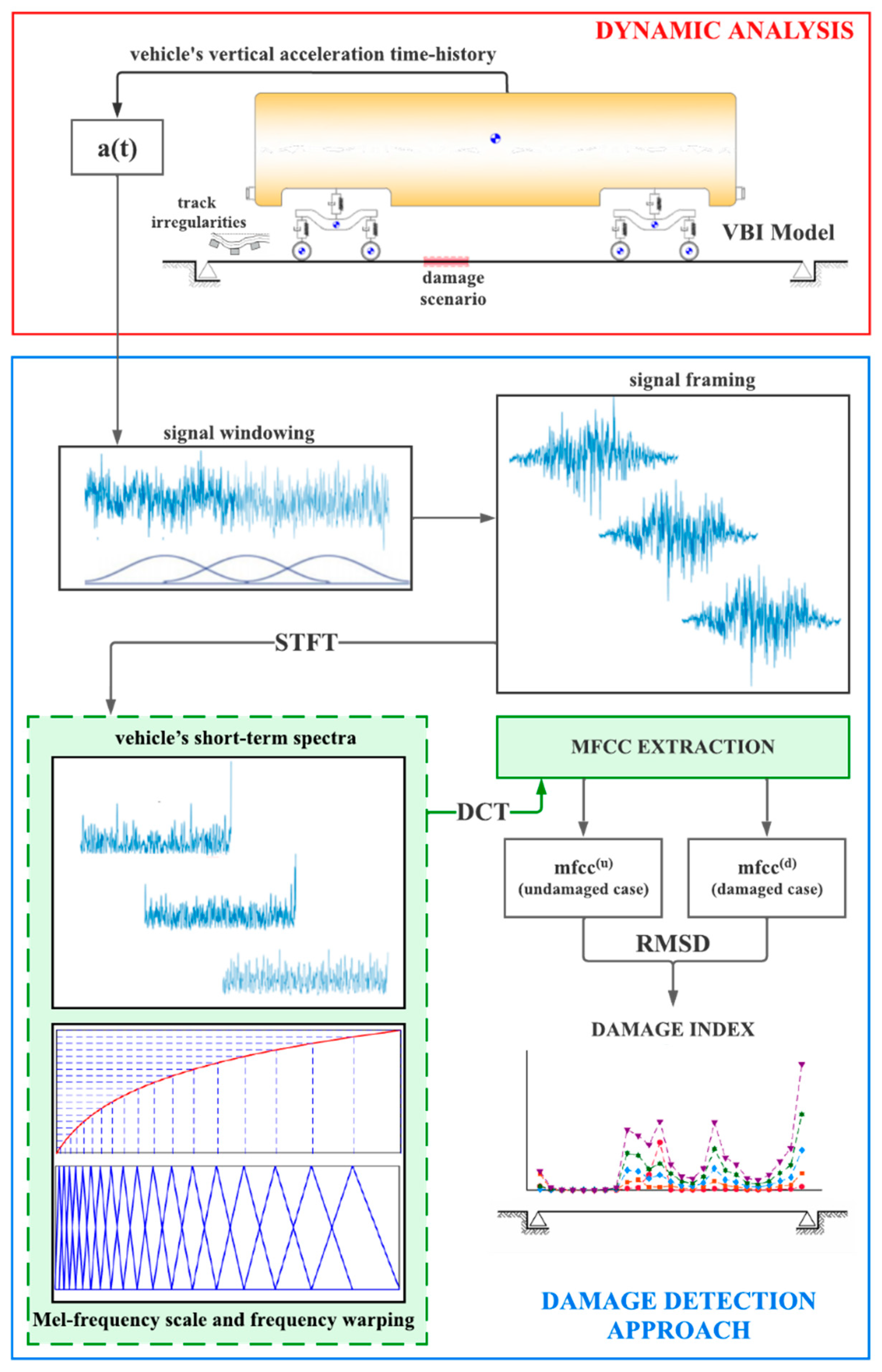
The framework proposed in this paper for drive-by damage detection of HSR bridges using MFCC for feature extraction is discussed in this section, and can be summarized by the flow chart depicted in Figure 3.

2.3.1. Vehicle’s Acceleration Segmentation Short-Term Spectra

The Short-time Fourier Transform (STFT) is used to analyze how the frequency content of the vehicle’s acceleration signal changes over time. Thus, the vehicle’s vertical acceleration time history responses for both the healthy (undamaged) scenario and a damaged one, respectively a u t and a d t , are discretized into j segments, by sliding a window function over them. This function hops through the original signals at intervals of a pre-established number of samples. After segmentation and windowing, the vehicle’s short-term spectra of each frame of both cases, X j u f and X j d f , are obtained by the STFT by taking the discrete fourier transform (DFT) of all the segments.
This work used the Hanning window function in the signal time discretization. When dealing with non-stationary signals, as is the case for a variety of structural response time-histories, the framing and windowing techniques are particularly advantageous. In fact, when the monitored system is excited by a very non-stationary input, such as high-speed train excitation in a bridge, the response exhibits non-stationarity features in its transient part, which is frequently the only time history recorded for short-term SHM applications [58].

2.3.2. Adapted Mel-Frequency Scale and Frequency Warping

After the STFT has been evaluated, the frequency spectrum of each frame, in a procedure known as frequency warping, is undertaken to emphasize the signal’s Mel-frequency characteristics.
Although MFC is used for numerous applications, there is no single formula for the correspondence between Hertz and Mel frequency scales. The most widely used is given by
m = 1127 ln 1 + f / 700 ,
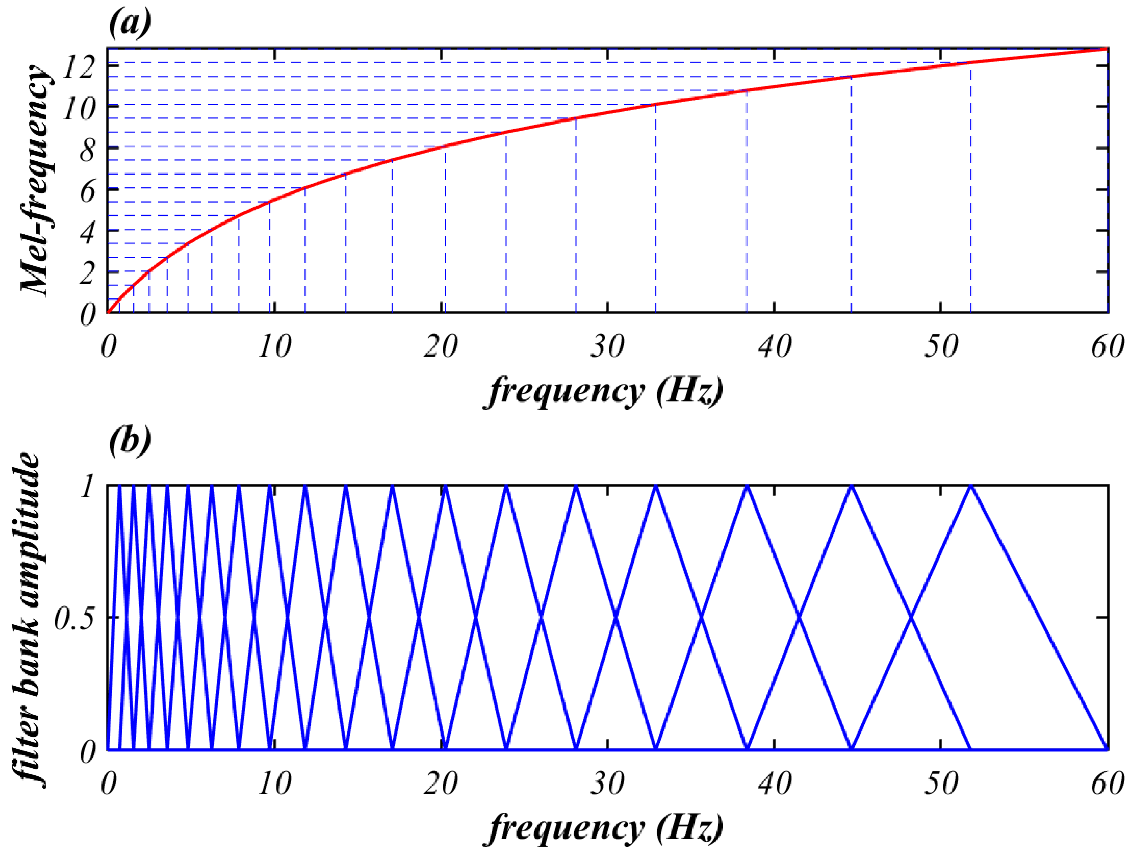
where m is the Mel-scale frequency, and f is the Hertz-scale frequency. Considering that lower frequency of bridges is always more important, an adapted formula for the transformation, to mimic the trending of Mel-scale in Equation (4) was proposed by [62] and is as follows
m = 5 ln 1 + f / 5 ,
where m is the Mel-scale frequency, and f is the Hertz-scale frequency.
Frequency warping is accomplished by applying a set of N triangular filters, called filter bank, to weigh the DFT values. The filter bank points are uniformly spaced on the Mel-frequency scale, and their centers are symmetric with respect to one another [61]. This procedure reduces distorted information in the spectrum (or Mel-spectra, or cepstrum) of the vehicle responses at high frequencies, higher than the significant ones from the bridge. For exemplification purposes, Figure 4 shows a frequency warping for a filter bank composed of twenty filters whose Hertz-scale frequency range from 0 to 60 Hz.

2.3.3. Mel-Frequency Cepstral Coefficients (MFCC)

The next step is obtaining the list of MFCC associated with the short-term spectra. The inverse discrete cosine transform (DCT) is employed, and then the m f c c j discrete vector related to j th short-term cepstrum X j f becomes
m f c c j = m f c c k j T ,   k = 1 , 2 , , N f 2 ,
with the k th component m f c c k j given by
m f c c k j = n = 2 N f 1 L o g X n cos π N 2 n 3 2 k
In Equations (6) and (7), N f is the number of filters in the filter bank, and L o g X n denotes the n th filter log-energy output, which can be written as
L o g X n = log l = 1 L T F n f × X j f 2 ,
in which T F n is the n th triangular filter that is applied over the j th short-term power spectrum X j f 2 , in its l = 1 , 2 , , L samples.

2.3.4. Damage Index

In the last stage of the procedure, MFCC are used to calculate the damage indices (DI), from which the HSR bridge damage prognosis is performed by comparing the aforementioned m f c c j u vectors extracted from the recorded vehicle’s responses when it crosses the undamaged bridge, with the m f c c j d ones provided by the vehicle passing over the bridge under the presence of damage. The along bridge span DI are taken by the Root Mean Square Deviation described as
D I j = k = 1 N 2 m f c c k j u m f c c k j d 2 k = 1 N 2 m f c c k j u 2 .

3. Numerical Simulations: Results and Discussion

The previously discussed VBI model and the drive-by damage detection procedure were implemented in MATLAB® [64], and the feasibility of using damage features extracted from MFCC in indirect SHM of HSR infrastructure is numerically evaluated in this section for two different levels of track conditions: low disturbance (LD) and high disturbance (HD) (as described in Section 2.2), in addition to the case where no irregularity is considered (NC), for train speeds of 144   k m / h and 288   k m / h . To analyze the sensitivity of the method regarding the intensity of the damage, five damage scenarios were simulated on the bridge, assuming bending stiffness reductions of f s r = 5 % ,   10 % ,   15 % ,   20 % and 25% in a region of the Euler-Bernoulli beam with 1.2   m length (The bridge span is L = 45   m ). On the other hand, to verify the sensitivity of MFFC-based DI as to the damage location, these damage scenarios were considered for different cases, in which these regions were located around the cross-section situated at the midspan and at 1/4 of the span from the left support.
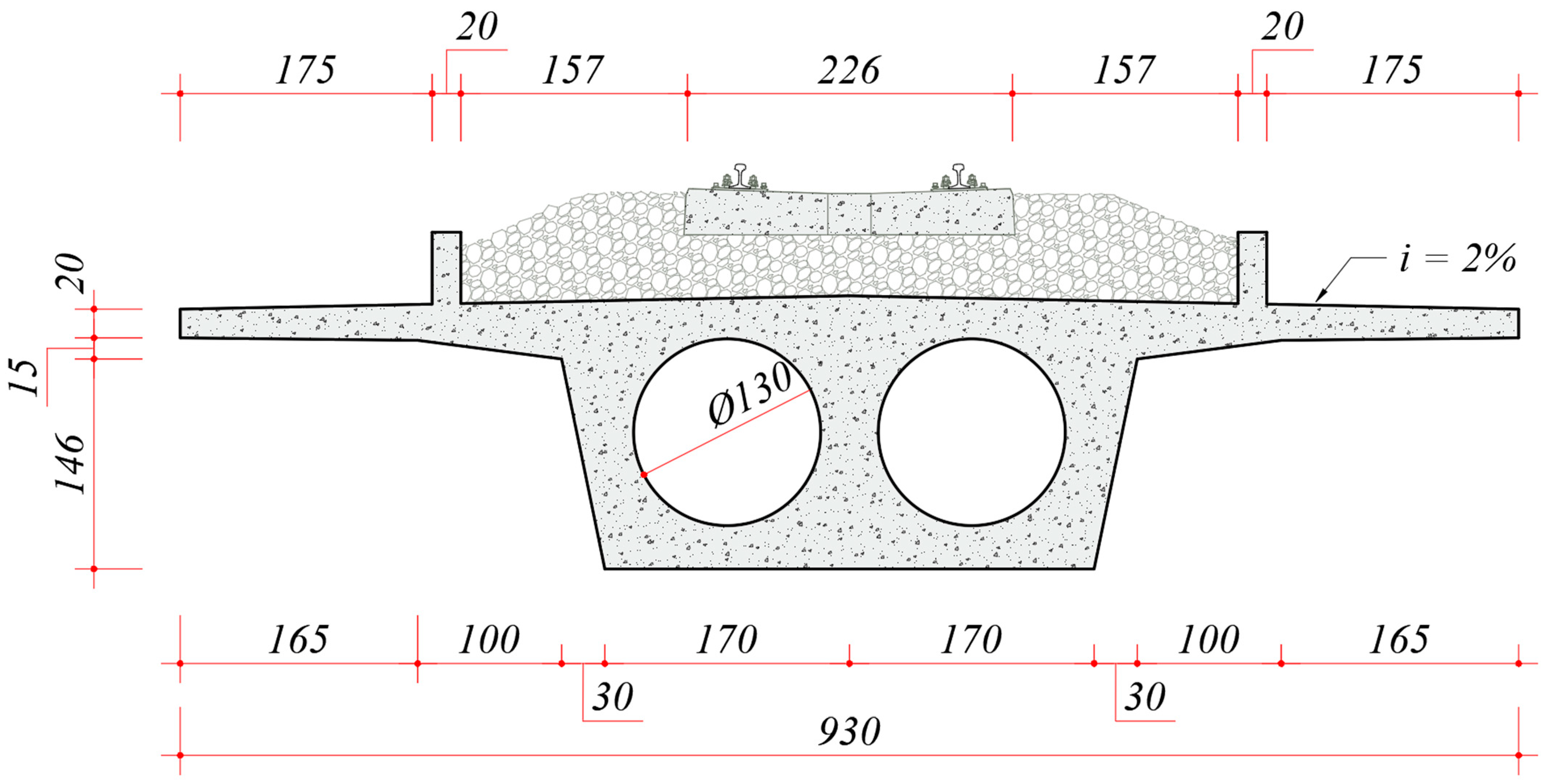
The bridge parameters are summarized in Table 2 and were determined from an idealized cross-section with a reinforced concrete deck and ballasted track (Figure 5). The rail profile was assumed to be smooth, and a track length of 40 m was considered before the bridge. The VTBI model was discretized with a bridge mesh size of 0.6 m, a rail mesh size of 0.2 m. At the first and second bridge modes, the Rayleigh damping coefficients were set to achieve a damping ratio of 0.5%. Vehicle properties were assumed for the Siemens ICE3 Velaro High-Speed Train [69] and are listed in Table 3.

3.1. Dynamic Analysis

In the dynamic analyses, a train composed of three cars was considered for all the numerical simulations. VTBI’s equations of motion system—Equation (1)—were solved by Newmark- β method algorithm, considering a constant time step Δ t equal to 0.0005   s.
In the assembly of the global VTBI matrices of Equation (4), on the bridge level, the structural damping was computed assuming Rayleigh proportional damping, defined by setting a damping ratio of ν = 2.5 % for the bridge’s first and second vertical mode. Table 4 presents the first eight natural frequency values of the bridge. The obtained vehicle’s natural frequency values and their corresponding mode shapes are enumerated in Table 5.

3.1.1. Bridge Response

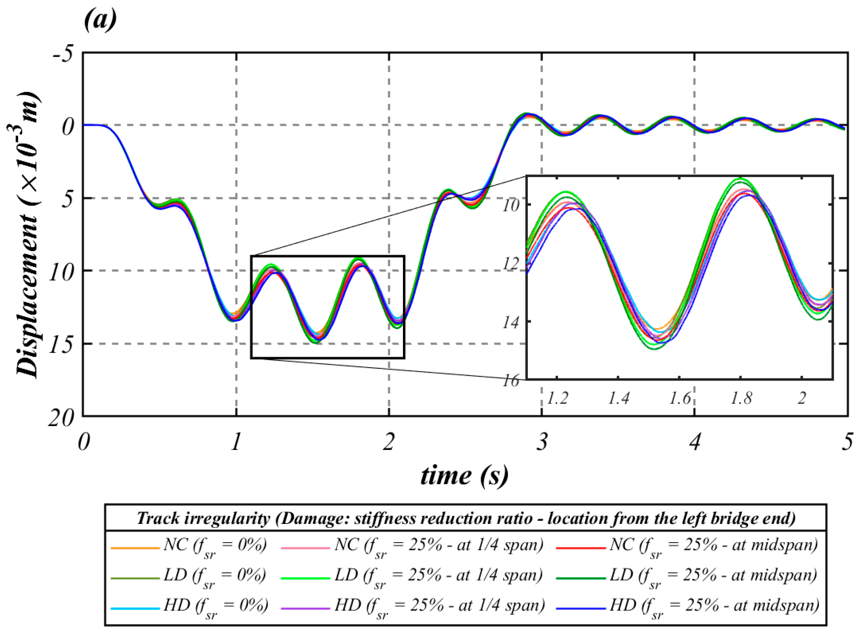
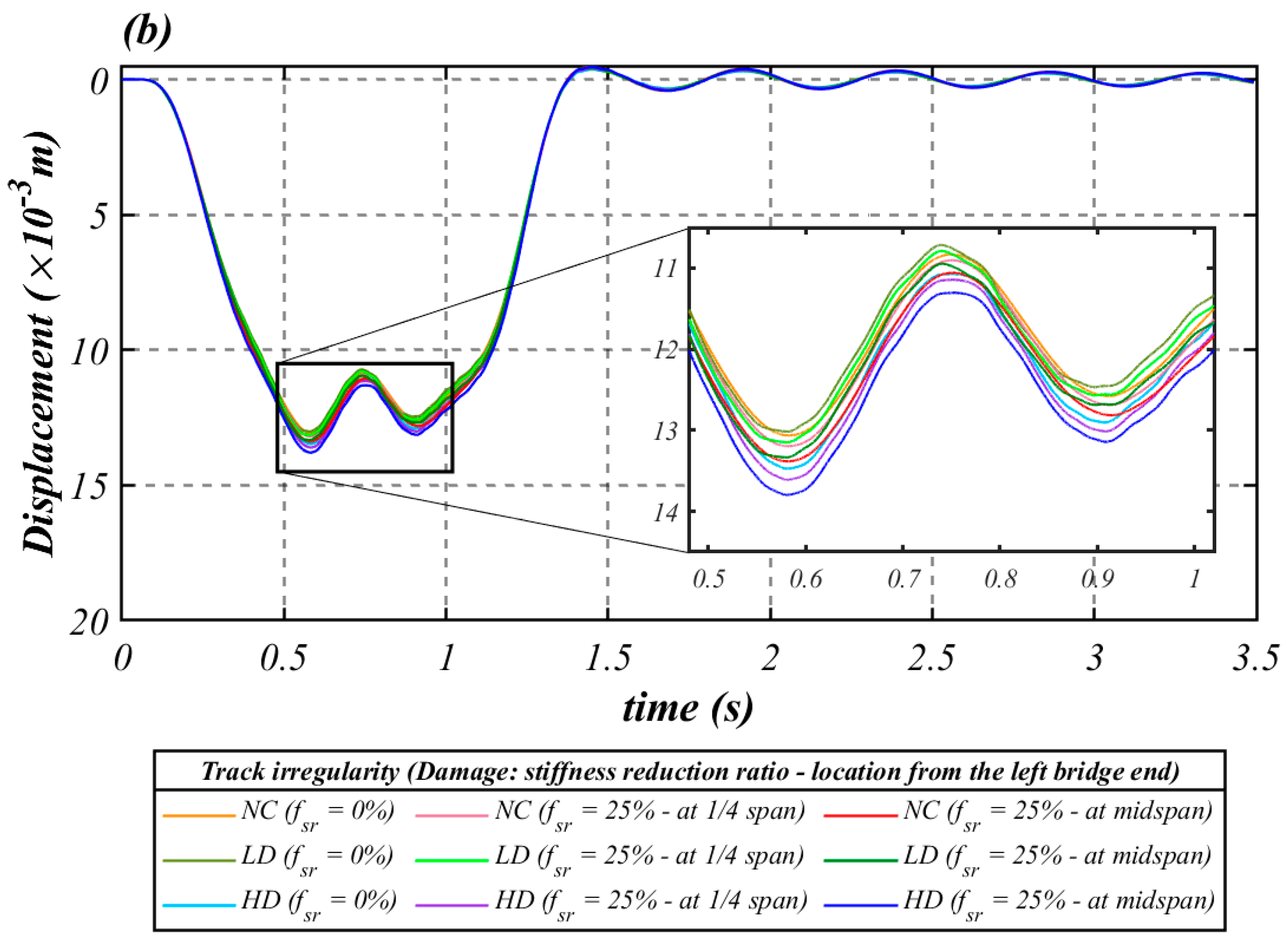
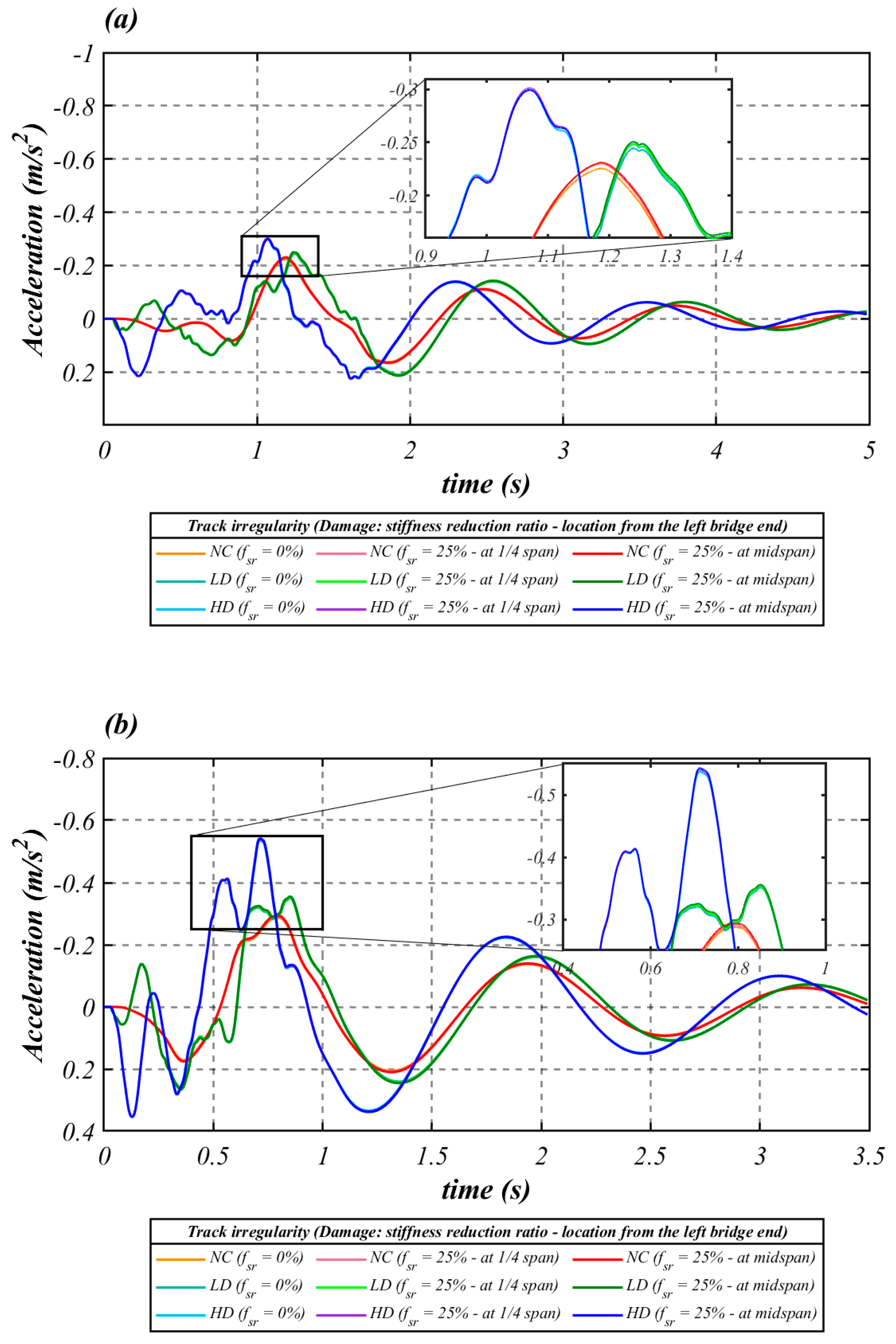
In order to analyze the impact of track irregularities and damage conditions on the bridge response, the displacements (Figure 6) and accelerations (Figure 7) at midspan were compared for the two operating speeds mentioned above, with respect to the three track irregularity levels and to two damage conditions, where f s r = 0 (undamaged case) and f s r = 25 % (the most extreme condition) were located at the midspan and 1/4 of the span from the left support, respectively.
Regarding the influence of the track conditions, it can be observed that the irregularities do not considerably impact the vertical displacement response of the structure (the maximum variation between results was limited to the order of 1 mm). However, in contrast, some influence is observed on the vertical acceleration response. The same considerations can be observed regarding the influence of the simulated damage conditions on the dynamic behavior of the bridge, but with the exception that, with increasing speed, the influence of the damage condition for the same level of track irregularity reduces significantly.

3.1.2. Vehicle Response

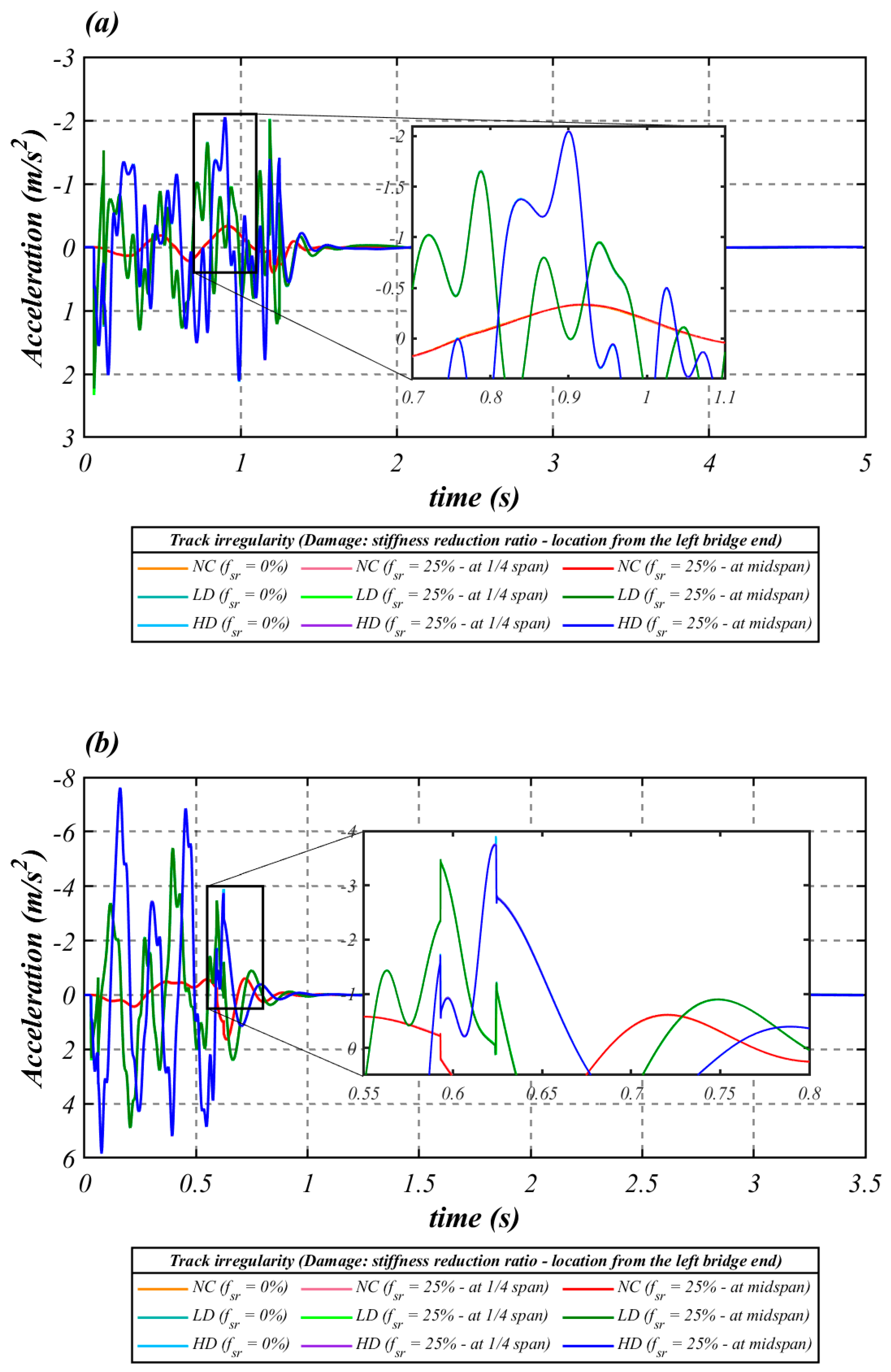
In order to evaluate the influence of track and damage conditions on the responses of the vehicle components, the time-histories of the vertical acceleration of the carbody and the front bogie are depicted in Figure 8 and Figure 9, respectively, for the same scenarios used for the previous discussion on the bridge response.
In contrast to what was observed for the bridge, the degree of track irregularity significantly influences the dynamic responses of both vehicle components. As for the effect of structural damage on vehicle responses, the following observations are worth noting:
  • As shown in Figure 9, different damage conditions are not visibly distinguished by the bogie responses. However, due to the reduction provided by the secondary suspension system in both the frequencies and the amplitude of the carbody’s responses relative to those of the bogie, different damage conditions were picked up by the car body’s vertical accelerations, albeit subtly. For this reason, the methodology proposed in this paper was applied, concerning the carbody accelerations.
  • Figure 8a,b shows that the differences between the responses to damage severity become less apparent with increasing speed. This aspect represents the main challenge to be overcome in developing vibration-based drive-by damage detection methodologies for indirect SHM of HSR bridges.

3.2. Performance of the Proposed Drive-by Damage Detection Using MFCC

To analyze the performance of the proposed damage detection procedure, all the scenarios described at the beginning of this section were used to obtain the results discussed below. The post-processing of the output data from the dynamic analyses for extracting the MFCC and obtaining the short-term DI were carried out according to the following considerations:
  • The output dataset corresponding to the time-histories of the carbody’s vertical acceleration recorded at each case were corrupted by 5% white noise, to simulate the effect of measurement disturbances.
  • No bandpass filters were used in the signal processing, since this procedure is already covered in the frequency warping stage, with the filter bank application.
  • The filter bank was configured with 50 triangular filters, whose corresponding 50 frequency values in Hertz, equally spaced on a Mel-frequency scale, had a cut-off frequency of 60 Hz.
  • For the segmentation/windowing of the carbody’s signal recorded, the STFT was set up with a window function length of 2 11 samples (22 frames) to guarantee enough segments for damage identification on the bridge. Moreover, as the window functions taper off at the edges to avoid spectral ringing, the corresponding overlapping used was 34/64 of the windowing length.

Damage Detection Performance

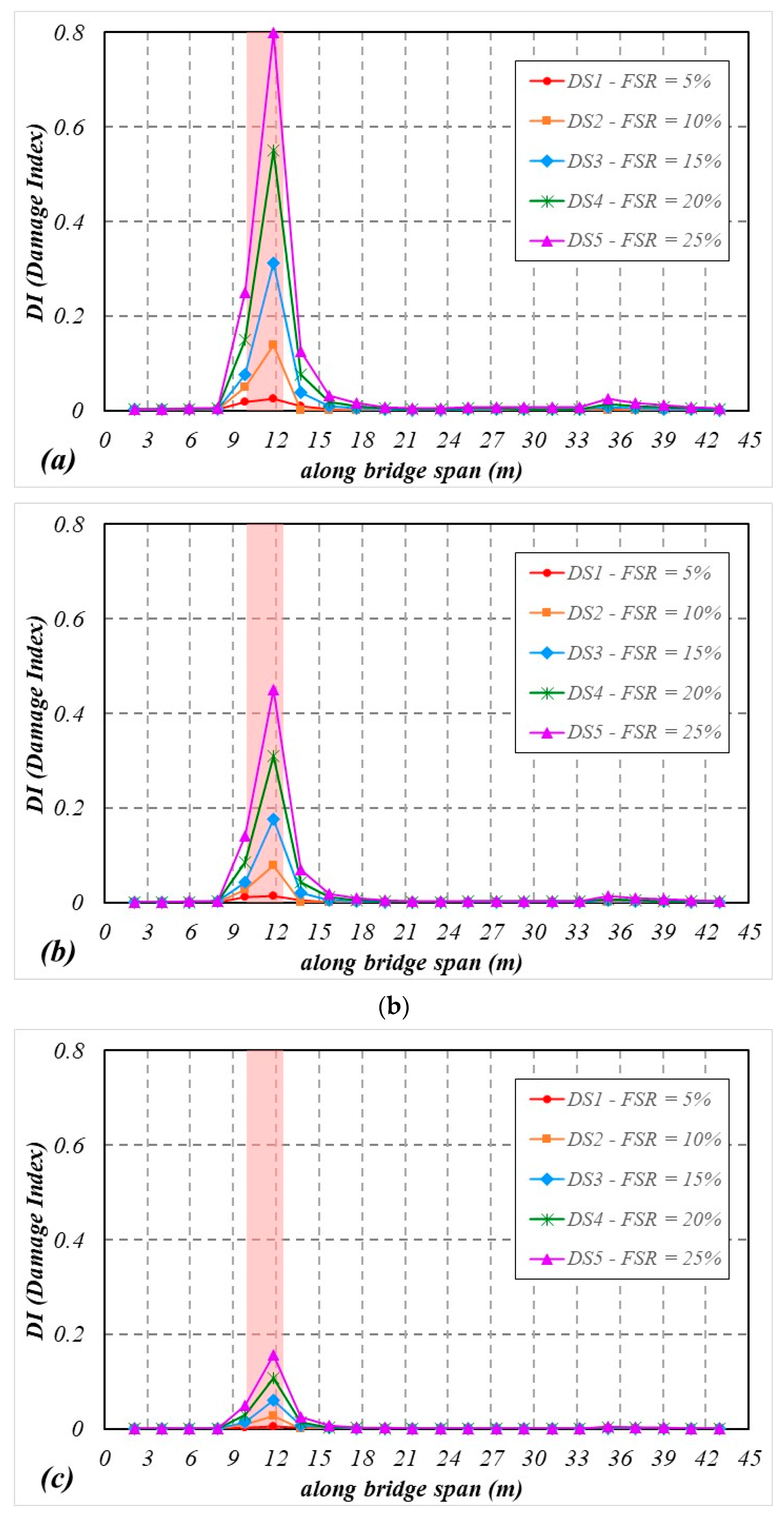
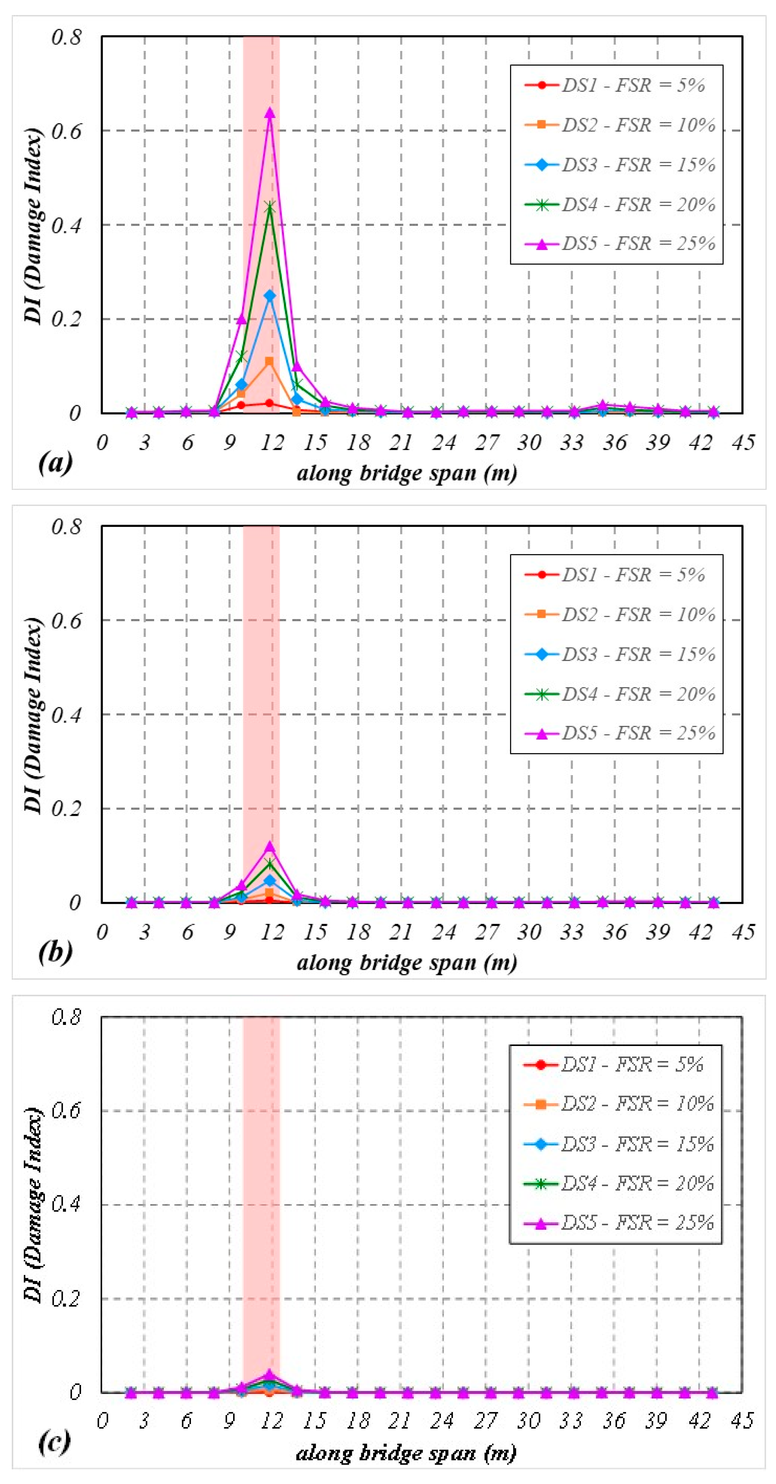
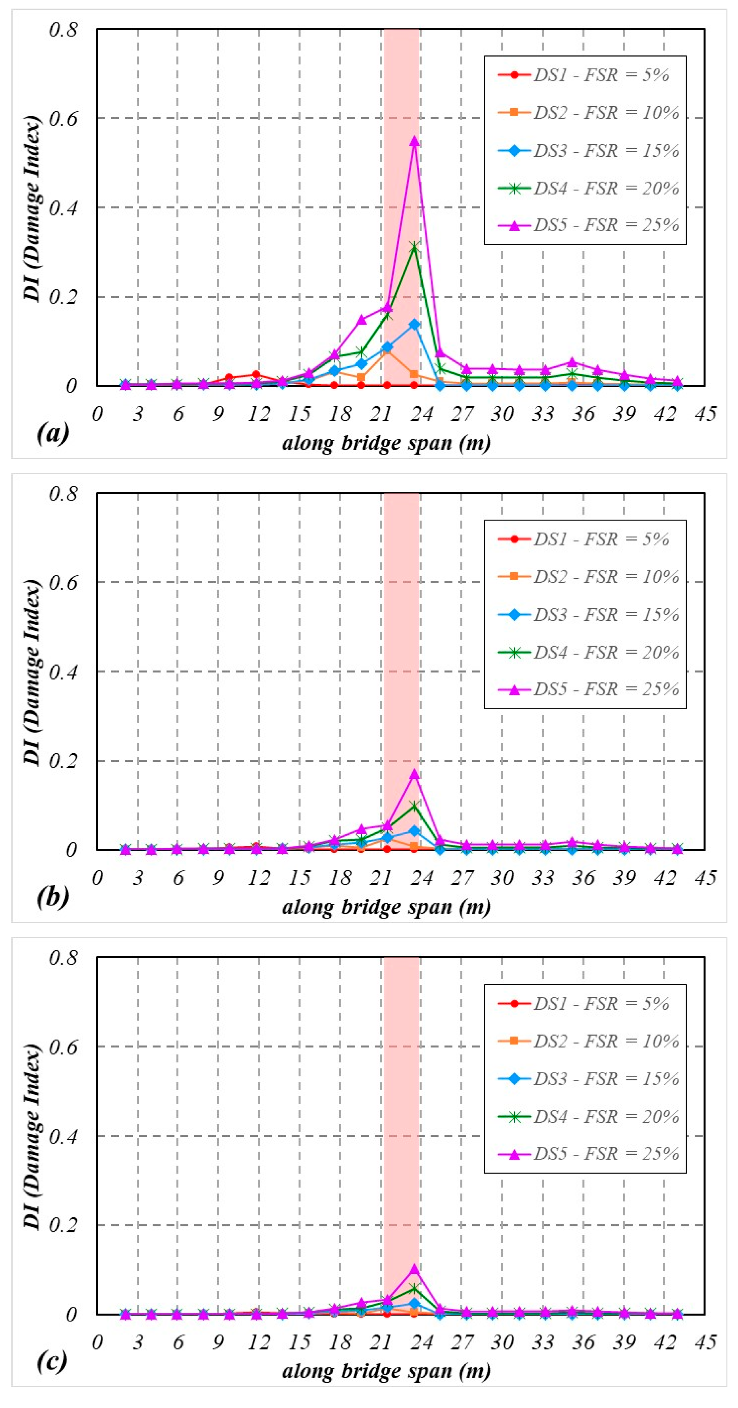
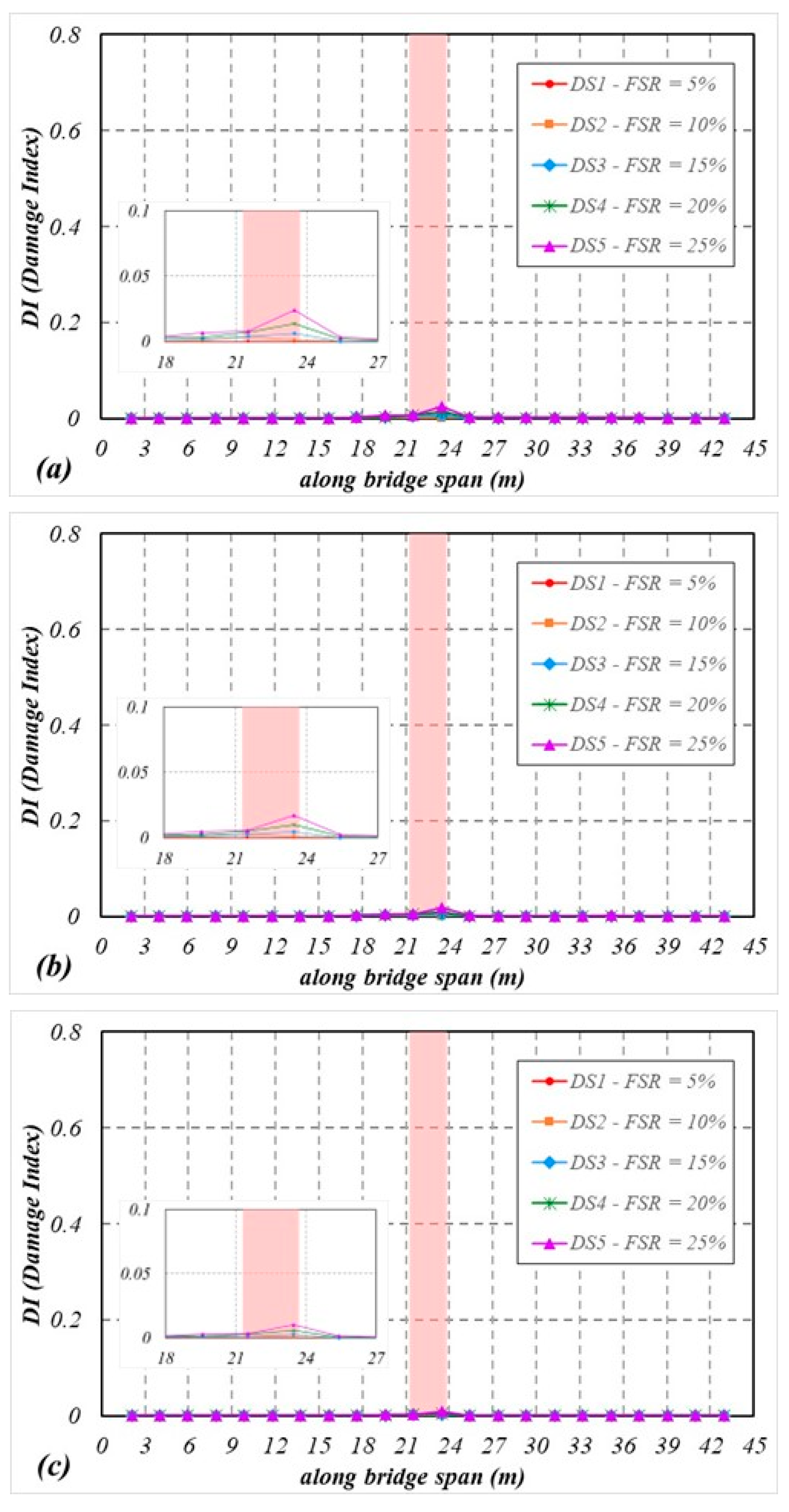
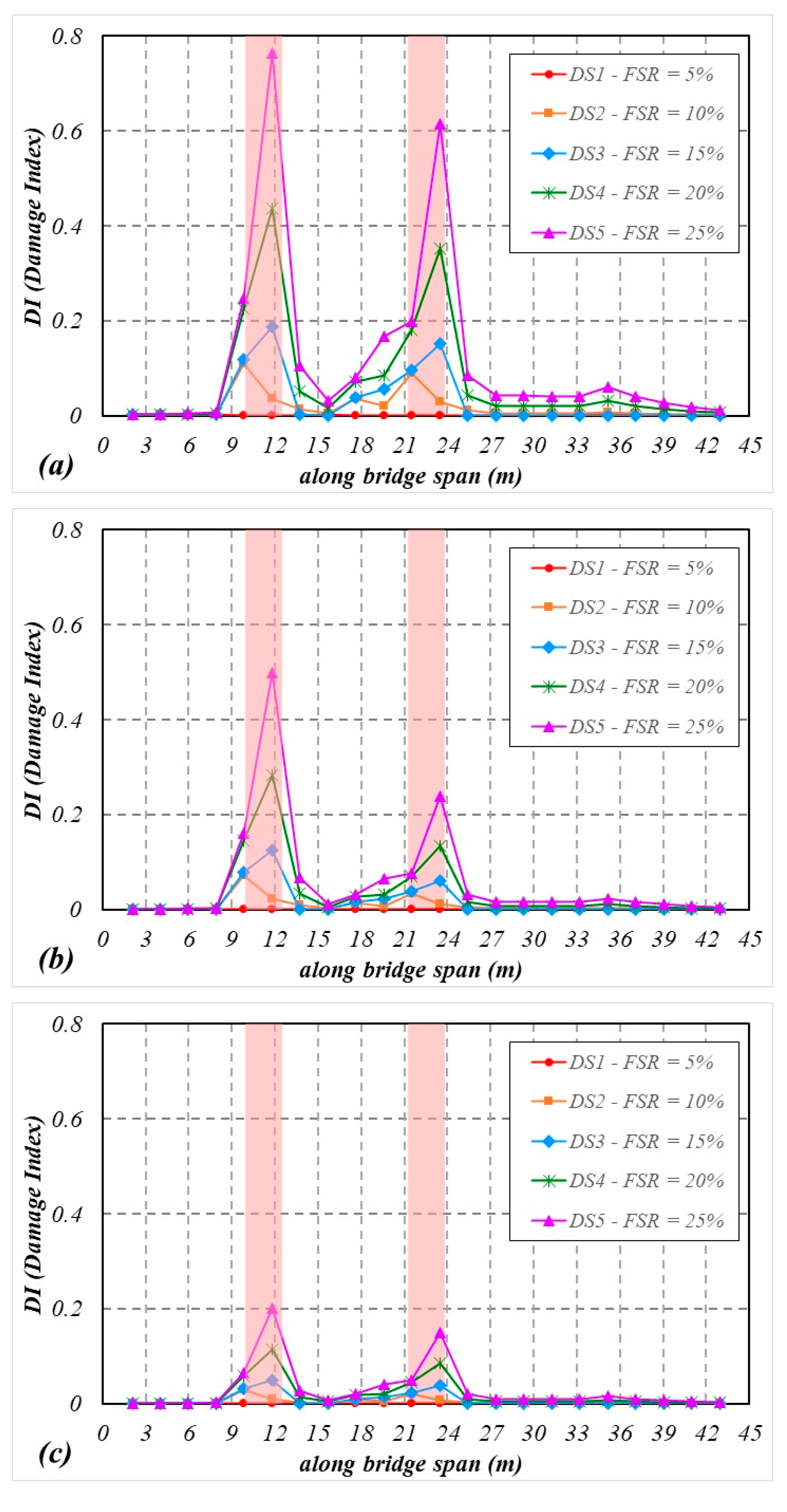
The performance of MFCC in providing DI that can determine whether the system is under a structural damaged condition is now being discussed. Figure 10 and Figure 11 display, for the train running speeds of v = 144   k m / h and v = 288   k m / h , respectively, the DI values obtained for the cases where different damage scenarios were applied in the section at 1/4 of the span, under the three levels of track irregularities mentioned earlier. Analogously, Figure 12 and Figure 13 show the DI values obtained for the same conditions, but with the damage located at mid-span.
By looking at these graphics (Figure 10, Figure 11, Figure 12 and Figure 13), one can immediately see that the DI values obtained from MFCC provided robust features regarding the location of the damage. The DI values were able to indicate accurately the damage location and severity in all cases.
It can also be seen that, although the sensitivity of the proposed DI to the degree of damage and its location is unaffected, the magnitude of the feature correlates with both the speed at which the vehicle passes over the bridge and the degree of track irregularities. In this last aspect, the detectability of the technique corroborates the fact that abnormal excitations induced by roadway irregularities are more expressive than damage (especially for slight damage).
Figure 14 shows that for a multiple damage scenario, it is observed that the DI values are approximately the same as those observed for singular damage scenarios.
The different patterns of distribution of its values, in response to different damage conditions and sources of excitation, together with the potential to detect the presence and severity of the damage, suggest its feasibility and the merits of investigating its application in a drive-by methodology for damage detection of HSR bridges in a pattern recognition approach. Once these cepstrum-based features become available, they can be statistically analyzed to recognize their pattern and correlate it to a damage location.

4. Conclusions and Prospects

This research assesses the applicability of MFCC to a drive-by damage detection approach for HSR bridges. The proposed framework was implemented in MATLAB, and, using numerical simulations, damage indices (DI) were extracted from the root mean square deviation of the MFCC. They were calculated using the recorded vehicle responses when it crossed an undamaged bridge and those obtained when it passed over the structure, under induced damage scenarios in which a region of the bridge had a bending stiffness reduction in a delimited extension of its length. The dynamic analyses were performed using a finite element (FEM) 2D VTBI model that incorporates the train, ballasted track and bridge behavior. The influence of external excitations such as measurement noises and different levels of track irregularities in the methodology effectiveness were explored. Finally, the key results were summarized in the last section, and some prospects were highlighted. The results presented in this study should be seen as a first attempt to link cepstrum-based features in an HSR drive-by damage detection approach. The following major conclusions are obtained from our analysis:
  • The DI values acquired from MFCC offer robust information regarding the location of the damage. In all circumstances, the DI values reliably reflect the location and severity of the damage.
  • The amplitude of the feature extracted from MFCC correlates with the vehicle’s speed over the bridge and the degree of track irregularities. The DI values are more sensitive to excitation sources caused by track irregularities than those induced by damage.
  • The results indicate that the distribution patterns of DI differ concerning different damage locations, with a tendency to exhibit peaks near these damaged zones.
  • In this paper, no attempt has been made to apply any dimensionality reduction techniques to the extracted features, such as principal component analysis, in which a linear mapping of the MFCC can be performed to extract the components more likely to be influenced by structural properties than by other excitation sources. Neither have more sophisticated techniques such as deep learning or time series analysis been applied, to compare the statistical distributions of the MFCC and extract damage location from them. These prospects will be investigated in the future.

Author Contributions

Conceptualization, E.F.d.S.; methodology, E.F.d.S.; software, E.F.d.S.; validation, E.F.d.S.; formal analysis, E.F.d.S.; investigation, E.F.d.S.; writing—original draft preparation, E.F.d.S.; writing—review and editing, D.R. and H.C.; visualization, D.R., T.N.B. and H.C.; supervision, T.N.B. and D.R.; project administration, T.N.B. All authors have read and agreed to the published version of the manuscript.

Funding

This research received no external funding.

Institutional Review Board Statement

Not applicable.

Informed Consent Statement

Not applicable.

Data Availability Statement

Not applicable.

Conflicts of Interest

The authors declare no conflict of interest.

References

  1. Li, Z.; Li, S.; Lv, J.; Li, H. Condition Assessment for High-Speed Railway Bridges Based on Train-Induced Strain Response. Struct. Eng. Mech. 2015, 54, 199–219. [Google Scholar] [CrossRef]
  2. Montenegro, P.A.; Calçada, R.; Carvalho, H.; Bolkovoy, A.; Chebykin, I. Stability of a Train Running over the Volga River High-Speed Railway Bridge during Crosswinds. Struct. Infrastruct. Eng. 2020, 16, 1121–1137. [Google Scholar] [CrossRef]
  3. Wang, Y.; Wang, P.; Tang, H.; Liu, X.; Xu, J.; Xiao, J.; Wu, J. Assessment and Prediction of High Speed Railway Bridge Long-Term Deformation Based on Track Geometry Inspection Big Data. Mech. Syst. Signal Process. 2021, 158, 107749. [Google Scholar] [CrossRef]
  4. Yang, Y.B.; Xu, H.; Zhang, B.; Xiong, F.; Wang, Z.L. Measuring Bridge Frequencies by a Test Vehicle in Non-Moving and Moving States. Eng. Struct. 2020, 203, 109859. [Google Scholar] [CrossRef]
  5. Zhan, J.; Wang, Z.; Kong, X.; Xia, H.; Wang, C.; Xiang, H. A Drive-by Frequency Identification Method for Simply Supported Railway Bridges Using Dynamic Responses of Passing Two-Axle Vehicles. J. Bridge Eng. 2021, 26, 04021078. [Google Scholar] [CrossRef]
  6. Hester, D.; Gonzalez, A. A Discussion on the Merits and Limitations of Using Drive-by Monitoring to Detect Localised Damage in a Bridge. Mech. Syst. Signal Process. 2017, 90, 234–253. [Google Scholar] [CrossRef] [Green Version]
  7. Yang, Y.B.; Yang, J.; Zhang, B.; Wu, Y. Vehicle Scanning Method for Bridges; John Wiley & Sons Ltd.: Hoboken, NJ, USA, 2019; ISBN 9781119539582. [Google Scholar]
  8. Cheema, P.; Alamdari, M.M.; Chang, K.C.; Kim, C.W.; Sugiyama, M. A Drive-by Bridge Inspection Framework Using Non-Parametric Clusters over Projected Data Manifolds. Mech. Syst. Signal Process. 2022, 180, 109401. [Google Scholar] [CrossRef]
  9. Matsuoka, K.; Tanaka, H.; Kawasaki, K.; Somaschini, C.; Collina, A. Drive-by Methodology to Identify Resonant Bridges Using Track Irregularity Measured by High-Speed Trains. Mech. Syst. Signal Process. 2021, 158, 107667. [Google Scholar] [CrossRef]
  10. Yang, Y.-B.; Lin, C.W.; Yau, J.D. Extracting Bridge Frequencies from the Dynamic Response of a Passing Vehicle. J. Sound Vib. 2004, 272, 471–493. [Google Scholar] [CrossRef]
  11. Lin, C.W.; Yang, Y.B. Use of a Passing Vehicle to Scan the Fundamental Bridge Frequencies: An Experimental Verification. Eng. Struct. 2005, 27, 1865–1878. [Google Scholar] [CrossRef]
  12. Yang, Y.B.; Chang, K.C. Extracting the Bridge Frequencies Indirectly from a Passing Vehicle: Parametric Study. Eng. Struct. 2009, 31, 2448–2459. [Google Scholar] [CrossRef]
  13. Yang, Y.B.; Chang, K.C.; Li, Y.C. Filtering Techniques for Extracting Bridge Frequencies from a Test Vehicle Moving over the Bridge. Eng. Struct. 2013, 48, 353–362. [Google Scholar] [CrossRef]
  14. Kim, C.W.; Isemoto, R.; Toshinami, T.; Kawatani, M.; McGetrick, P.J.; O’Brien, E.J. Experimental Investigation of Drive-by Bridge Inspection. In Proceedings of the SHMII-5 2011—5th International Conference on Structural Health Monitoring of Intelligent Infrastructure, Cancun, Mexico, 11–15 December 2011. [Google Scholar]
  15. Cerda, F.; Chen, S.; Bielak, J.; Garrett, J.H.; Rizzo, P.; KovaČević, J. Indirect Structural Health Monitoring of a Simplified Laboratory-Scale Bridge Model. Smart Struct. Syst. 2014, 13, 849–868. [Google Scholar] [CrossRef]
  16. Chang, K.-C.; Kim, C.-W.; Kawatani, M. Feasibility Investigation for a Bridge Damage Identification Method through Moving Vehicle Laboratory Experiment. Struct. Infrastruct. Eng. 2014, 10, 328–345. [Google Scholar] [CrossRef] [Green Version]
  17. Kim, C.W.; Isemoto, R.; Mcgetrick, P.J.; Kawatani, M.; Obrien, E.J. Drive-by Bridge Inspection from Three Different Approaches. Smart Struct. Syst. 2014, 13, 775–796. [Google Scholar] [CrossRef] [Green Version]
  18. Yang, Y.B.; Wang, Z.-L.; Shi, K.; Xu, H.; Wu, Y.T. State-of-the-Art of Vehicle-Based Methods for Detecting Various Properties of Highway Bridges and Railway Tracks. Int. J. Struct. Stab. Dyn. 2020, 20, 2041004. [Google Scholar] [CrossRef]
  19. Elhattab, A.; Uddin, N.; OBrien, E. Drive-by Bridge Damage Monitoring Using Bridge Displacement Profile Difference. J. Civ. Struct. Health Monit. 2016, 6, 839–850. [Google Scholar] [CrossRef]
  20. Locke, W.; Sybrandt, J.; Redmond, L.; Safro, I.; Atamturktur, S. Using Drive-by Health Monitoring to Detect Bridge Damage Considering Environmental and Operational Effects. J. Sound Vib. 2020, 468, 115088. [Google Scholar] [CrossRef]
  21. Elhattab, A.; Uddin, N.; OBrien, E. Drive-By Bridge Frequency Identification under Operational Roadway Speeds Employing Frequency Independent Underdamped Pinning Stochastic Resonance (FI-UPSR). Sensors 2018, 18, 4207. [Google Scholar] [CrossRef] [Green Version]
  22. Wang, H.; Nagayama, T.; Nakasuka, J.; Zhao, B.; Su, D. Extraction of Bridge Fundamental Frequency from Estimated Vehicle Excitation through a Particle Filter Approach. J. Sound Vib. 2018, 428, 44–58. [Google Scholar] [CrossRef]
  23. Reksowardojo, A.P.; Nagayama, T.; Su, D.; Mizutani, T. Bridge Natural Frequency Estimation by Extracting the Common Vibration Component from the Responses of Two Vehicles. Eng. Struct. 2017, 150, 821–829. [Google Scholar] [CrossRef]
  24. He, Y.; Yang, J.P. Using Acceleration Residual Spectrum from Single Two-Axle Vehicle at Contact Points to Extract Bridge Frequencies. Eng. Struct. 2022, 266, 114538. [Google Scholar] [CrossRef]
  25. Malekjafarian, A.; OBrien, E.J. Identification of Bridge Mode Shapes Using Short Time Frequency Domain Decomposition of the Responses Measured in a Passing Vehicle. Eng. Struct. 2014, 81, 386–397. [Google Scholar] [CrossRef] [Green Version]
  26. Li, J.; Zhu, X.; Law, S.; Samali, B. Indirect Bridge Modal Parameters Identification with One Stationary and One Moving Sensors and Stochastic Subspace Identification. J. Sound Vib. 2019, 446, 1–21. [Google Scholar] [CrossRef]
  27. Zhang, Y.; Wang, L.; Zhao, H.; Lie, S.T. Extraction of Mode Shapes of Beam-like Structures from the Dynamic Response of a Moving Mass. Acta Mech. Sin./Lixue Xuebao 2019, 35, 664–673. [Google Scholar] [CrossRef]
  28. Yang, Y.B.; Li, Z.; Wang, Z.L.; Shi, K.; Xu, H.; Qiu, F.Q.; Zhu, J.F. A Novel Frequency-Free Movable Test Vehicle for Retrieving Modal Parameters of Bridges: Theory and Experiment. Mech. Syst. Signal Process. 2022, 170, 108854. [Google Scholar] [CrossRef]
  29. Wang, Z.L.; Yang, J.P.; Shi, K.; Xu, H.; Qiu, F.Q.; Yang, Y.B. Recent Advances in Researches on Vehicle Scanning Method for Bridges. Int. J. Struct. Stab. Dyn. 2022, 2230005. [Google Scholar] [CrossRef]
  30. Nguyen, K.V.; Tran, H.T. Multi-Cracks Detection of a Beam-like Structure Based on the on-Vehicle Vibration Signal and Wavelet Analysis. J. Sound Vib. 2010, 329, 4455–4465. [Google Scholar] [CrossRef]
  31. Bowe, C.; Quirke, P.; Cantero, D.; Obrien, E.J. Drive-by Structural Health Monitoring of Railway Bridges Using Train-Mounted Accelerometers. In Proceedings of the COMPDYN 2015—5th ECCOMAS Thematic Conference on Computational Methods in Structural Dynamics and Earthquake Engineering, Crete Island, Greece, 25–27 May 2015; Papadrakakis, M., Papadopoulos, V.P.V., Eds.; National Technical University of Athens: Athens, Greece, 2015; pp. 1652–1663. [Google Scholar]
  32. Carnevale, M.; Collina, A.; Peirlinck, T. A Feasibility Study of the Drive-by Method for Damage Detection in Railway Bridges. Appl. Sci. 2019, 9, 160. [Google Scholar] [CrossRef] [Green Version]
  33. Micu, E.A.; Obrien, E.J.; Bowe, C.; Fitzgerald, P.; Pakrashi, V. Bridge Damage and Repair Detection Using an Instrumented Train. J. Bridge Eng. 2022, 27, 05021018. [Google Scholar] [CrossRef]
  34. Li, Z.; Au, F.T.K. Damage Detection of Bridges Using Response of Vehicle Considering Road Surface Roughness. Int. J. Struct. Stab. Dyn. 2015, 15, 1450057. [Google Scholar] [CrossRef]
  35. OBrien, E.J.; Malekjafarian, A.; González, A. Application of Empirical Mode Decomposition to Drive-by Bridge Damage Detection. Eur. J. Mech. A/Solids 2017, 61, 151–163. [Google Scholar] [CrossRef] [Green Version]
  36. Tan, C.; Elhattab, A.; Uddin, N. “Drive-by” Bridge Frequency-Based Monitoring Utilizing Wavelet Transform. J. Civ. Struct. Health Monit. 2017, 7, 615–625. [Google Scholar] [CrossRef]
  37. Yang, Y.B.; Yang, J.P. State-of-the-Art Review on Modal Identification and Damage Detection of Bridges by Moving Test Vehicles. Int. J. Struct. Stab. Dyn. 2017, 18, 1850025. [Google Scholar] [CrossRef]
  38. Yang, Y.B.; Wang, Z.L.; Shi, K.; Xu, H.; Mo, X.Q.; Wu, Y.T. Two-Axle Test Vehicle for Damage Detection for Railway Tracks Modeled as Simply Supported Beams with Elastic Foundation. Eng. Struct. 2020, 219, 110908. [Google Scholar] [CrossRef]
  39. An, Y.; Chatzi, E.; Sim, S.-H.; Laflamme, S.; Blachowski, B.; Ou, J. Recent Progress and Future Trends on Damage Identification Methods for Bridge Structures. Struct. Control Health Monit. 2019, 26, e2416. [Google Scholar] [CrossRef]
  40. He, Y.; Yang, J.P.; Li, Y.-F. A Three-Stage Automated Modal Identification Framework for Bridge Parameters Based on Frequency Uncertainty and Density Clustering. Eng. Struct. 2022, 255, 113891. [Google Scholar] [CrossRef]
  41. Qiao, L.; Esmaeily, A. An Overview of Signal-Based Damage Detection Methods. Appl. Mech. Mater. 2011, 94–96, 834–851. [Google Scholar] [CrossRef]
  42. Babajanian Bisheh, H.; Ghodrati Amiri, G.; Nekooei, M.; Darvishan, E. Damage Detection of Bridges Based on Combining Efficient Cepstral Coefficients. J. Vib. Control 2021, 27, 2279–2290. [Google Scholar] [CrossRef]
  43. Kong, X.; Cai, C.S.; Kong, B. Damage Detection Based on Transmissibility of a Vehicle and Bridge Coupled System. J. Eng. Mech. 2015, 141, 04014102. [Google Scholar] [CrossRef]
  44. Malekjafarian, A.; Golpayegani, F.; Moloney, C.; Clarke, S. A Machine Learning Approach to Bridge-Damage Detection Using Responses Measured on a Passing Vehicle. Sensors 2019, 19, 4035. [Google Scholar] [CrossRef] [PubMed] [Green Version]
  45. Bernardini, L.; Carnevale, M.; Somaschini, C.; Matsuoka, K.; Collina, A. A Numerical Investigation of New Algorithms for the Drive-by Method in Railway Bridge Monitoring. In Proceedings of the Proceedings of the International Conference on Structural Dynamic, EURODYN; Papadrakakis, M., Fragiadakis, M.P.C., Eds.; European Association for Structural Dynamics: Bochum, Germany, 2020; Volume 1, pp. 1033–1043. [Google Scholar]
  46. Hajializadeh, D. Deep-Learning-Based Drive-by Damage Detection System for Railway Bridges. Infrastructures 2022, 7, 84. [Google Scholar] [CrossRef]
  47. Hajializadeh, D. Deep Learning-Based Indirect Bridge Damage Identification System. Struct. Health Monit. 2022, 3. [Google Scholar] [CrossRef]
  48. Souza, E.F.; Bittencourt, T.N.; Ribeiro, D.; Carvalho, H. Development of Damage Detection Methodologies in Bridges Using Drive-by Methods and Machine Learning Algorithms: A Systematic Review of the Literature. In EUROSTRUCT 2021. Lecture Notes in Civil Engineering: Proceedings of the 1st Conference of the European Association on Quality Control of Bridges and Structures; Springer: Cham, Switzerland, 2022; Volume 200, pp. 123–131. [Google Scholar] [CrossRef]
  49. Li, H.; Wang, T.; Yang, J.P.; Wu, G. Deep Learning Models for Time-History Prediction of Vehicle-Induced Bridge Responses: A Comparative Study. Int. J. Struct. Stab. Dyn. 2022, 2350004. [Google Scholar] [CrossRef]
  50. Smith, W.A.; Randall, R.B. Cepstrum-Based Operational Modal Analysis Revisited: A Discussion on Pole–Zero Models and the Regeneration of Frequency Response Functions. Mech. Syst. Signal Process. 2016, 79, 30–46. [Google Scholar] [CrossRef]
  51. Randall, R.B.; Antoni, J.; Smith, W.A. A Survey of the Application of the Cepstrum to Structural Modal Analysis. Mech. Syst. Signal Process. 2019, 118, 716–741. [Google Scholar] [CrossRef]
  52. Dackermann, U.; Smith, W.A.; Randall, R.B. Damage Identification Based on Response-Only Measurements Using Cepstrum Analysis and Artificial Neural Networks. Struct. Health Monit. 2014, 13, 430–444. [Google Scholar] [CrossRef]
  53. Dackermann, U.; Smith, W.A.; Li, J.; Randall, R.B. On the Use of the Cepstrum and Artificial Neural Networks to Identify Structural Mass Changes from Response-Only Measurements. In Proceedings of the ISMA 2014—International Conference on Noise and Vibration Engineering and USD 2014—International Conference on Uncertainty in Structural Dynamics, Leuven, Belgium, 15–17 September 2014; Sas, P., Moens, D.D.H., Eds.; KU Leuven: Leuven, Belgium, 2014; pp. 3739–3750. [Google Scholar]
  54. Morgantini, M.; Betti, R.; Balsamo, L. Structural Damage Assessment through Features in Quefrency Domain. Mech. Syst. Signal Process. 2021, 147, 107017. [Google Scholar] [CrossRef]
  55. Randall, R.B. Cepstral Methods of Operational Modal Analysis. In Encyclopedia of Structural Health Monitoring; John Wiley & Sons, Ltd.: Hoboken, NJ, USA, 2009; ISBN 9780470061626. [Google Scholar]
  56. Bochud, N.; Gomez, A.M.; Rus, G.; Carmona, J.L.; Peinado, A.M. Robust Parametrization for Non-Destructive Evaluation of Composites Using Ultrasonic Signals. In Proceedings of the ICASSP, IEEE International Conference on Acoustics, Speech and Signal Processing—Proceedings, Prague, Czech Republic, 22–27 May 2011; pp. 1789–1792. [Google Scholar]
  57. Zhang, G.; Harichandran, R.S.; Ramuhalli, P. Application of Noise Cancelling and Damage Detection Algorithms in NDE of Concrete Bridge Decks Using Impact Signals. J. Nondestruct. Eval. 2011, 30, 259–272. [Google Scholar] [CrossRef]
  58. Balsamo, L.; Betti, R.; Beigi, H. A Structural Health Monitoring Strategy Using Cepstral Features. J. Sound Vib. 2014, 333, 4526–4542. [Google Scholar] [CrossRef]
  59. Tronci, E.M.; Beigi, H.; Feng, M.Q.; Betti, R. Damage Assessment in Structural Systems through Transfer Learning from Audio Domains. In Proceedings of the International Conference on Structural Health Monitoring of Intelligent Infrastructure: Transferring Research into Practice, SHMII; International Society for Structural Health Monitoring of Intelligent Infrastructure ISHMII: Brussels, Belgium, 2021; Volume 2021, pp. 805–811. [Google Scholar]
  60. Tronci, E.M.; Beigi, H.; Feng, M.Q.; Betti, R. Transfer Learning from Audio Domains a Valuable Tool for Structural Health Monitoring. In Proceedings of the Conference Proceedings of the Society for Experimental Mechanics Series; Grimmelsman, K., Ed.; Springer: Berlin/Heidelberg, Germany, 2022; pp. 99–107. [Google Scholar]
  61. Tronci, E.M.; Beigi, H.; Feng, M.Q.; Betti, R. A Transfer Learning SHM Strategy for Bridges Enriched by the Use of Speaker Recognition X-Vectors. J. Civ. Struct. Health Monit. 2022, 12. [Google Scholar] [CrossRef]
  62. Mei, Q.; Gül, M.; Boay, M. Indirect Health Monitoring of Bridges Using Mel-Frequency Cepstral Coefficients and Principal Component Analysis. Mech. Syst. Signal Process. 2019, 119, 523–546. [Google Scholar] [CrossRef]
  63. Yu, Z.; Shao, S.; Deng, G.; Zhou, Z. A Damage Detection Method of Bridges Utilizing Vehicle Vibration Time History Signal. In European Workshop on Structural Health Monitoring; Springer: Cham, Switzerland, 2021; Volume 127, pp. 367–377. [Google Scholar] [CrossRef]
  64. MATLAB Release Notes (R2022a); MATLAB: Natick, MA, USA, 2022.
  65. Zhai, W.; Han, Z.; Chen, Z.; Ling, L.; Zhu, S. Train–Track–Bridge Dynamic Interaction: A State-of-the-Art Review. Veh. Syst. Dyn. 2019, 57, 984–1027. [Google Scholar] [CrossRef] [Green Version]
  66. Zhai, W.; Xia, H.; Cai, C.; Gao, M.; Li, X.; Guo, X.; Zhang, N.; Wang, K. High-Speed Train–Track–Bridge Dynamic Interactions—Part I: Theoretical Model and Numerical Simulation. Int. J. Rail Transp. 2013, 1, 3–24. [Google Scholar] [CrossRef]
  67. Iwnicki, S.; Spiryagin, M.; Cole, C.; McSweeney, T. (Eds.) Handbook of Railway Vehicle Dynamics, 2nd ed.; CRC Press: Boca Raton, FL, USA, 2019. [Google Scholar]
  68. Nguyen, K.; Goicolea, J.M.; Galbadón, F. Comparison of Dynamic Effects of High-Speed Traffic Load on Ballasted Track Using a Simplified Two-Dimensional and Full Three-Dimensional Model. Proc. Inst. Mech. Eng. Part F J. Rail Rapid Transit. 2014, 228, 128–142. [Google Scholar] [CrossRef]
  69. Quirke, P.; Bowe, C.; OBrien, E.J.; Cantero, D.; Antolin, P.; Goicolea, J.M. Railway Bridge Damage Detection Using Vehicle-Based Inertial Measurements and Apparent Profile. Eng. Struct. 2017, 153, 421–442. [Google Scholar] [CrossRef]
  70. Cantero, D.; Arvidsson, T.; OBrien, E.; Karoumi, R. Train–Track–Bridge Modelling and Review of Parameters. Struct. Infrastruct. Eng. 2016, 12, 1051–1064. [Google Scholar] [CrossRef] [Green Version]
  71. Lou, P.; Au, F.T.K. Finite Element Formulae for Internal Forces of Bernoulli–Euler Beams under Moving Vehicles. J. Sound Vib. 2013, 332, 1533–1552. [Google Scholar] [CrossRef]
  72. Zhai, W. Vehicle–Track Coupled Dynamics: Theory and Applications; Springer: Berlin/Heidelberg, Germany, 2020; ISBN 978-981-32-9282-6. [Google Scholar]
  73. Lou, P. Finite Element Analysis for Train–Track–Bridge Interaction System. Arch. Appl. Mech. 2007, 77, 707–728. [Google Scholar] [CrossRef]
  74. Lei, X.; Noda, N.-A. Analyses of Dynamic Response of Vehicle and Track Coupling System with Random Irregularity of Track Vertical Profile. J. Sound Vib. 2002, 258, 147–165. [Google Scholar] [CrossRef]
  75. Podwórna, M. Modelling of Random Vertical Irregularities of Railway Tracks. Int. J. Appl. Mech. Eng. 2015, 20, 647–655. [Google Scholar] [CrossRef] [Green Version]
  76. Lee, J.; Choi, H.; Park, D.; Chung, Y.; Kim, H.-Y.; Yoon, S. Fault Detection and Diagnosis of Railway Point Machines by Sound Analysis. Sens. 2016, 16, 549. [Google Scholar] [CrossRef] [PubMed]
  77. Calçada, R.; Delgado, R.; Campos e Matos, A. (Eds.) Bridges for High-Speed Railways: Revised Papers from the Workshop, Porto, Portugal, 3–4 June 2004, 1st ed.; CRC Press: Boca Raton, FL, USA, 2008; ISBN 9780429207396. [Google Scholar]
Figure 1. 2-D vehicle-track-bridge dynamic interaction system: (a) vehicle model, (b) track model, and (c) bridge model.
Sustainability 14 13290 g001
Figure 2. Track irregularities profiles.
Sustainability 14 13290 g002
Figure 3. Flowchart of the drive-by damage detection approach using MFCC.
Sustainability 14 13290 g003
Figure 4. Frequency warping: (a) Mel-frequency mapping using Equation (5), and (b) correspondent triangular filter bank.
Sustainability 14 13290 g004
Figure 5. Idealized cross-section of the bridge numerical model (Adapted from [77]).
Sustainability 14 13290 g005
Figure 6. Time-histories of the bridge vertical displacements at the midspan for different track and damage conditions; and for different operating speeds: (a) v = 144   km / h and (b) v = 288   km / h . (The y-axis was reversed, according to the positive direction adopted in the VBI modeling).
Sustainability 14 13290 g006aSustainability 14 13290 g006b
Figure 7. Time-histories of the bridge vertical accelerations at the midspan for different track and damage conditions, and for different operating speeds: (a) v = 144   km / h and (b) v = 288   km / h . (The y-axis was reversed, according to the positive direction adopted in the VBI modeling).
Sustainability 14 13290 g007aSustainability 14 13290 g007b
Figure 8. Time-histories of the carbody vertical accelerations for different track and damage conditions, and for different operating speeds: (a) v = 144   km / h and (b) v = 288   km / h . (The y-axis was reversed, according to the positive direction adopted in the VBI modeling).
Sustainability 14 13290 g008
Figure 9. Time-histories of the front bogie vertical accelerations for different track and damage conditions, and for different operating speeds: (a) v = 144   km / h and (b) v = 288   km / h . (The y-axis was reversed, according to the positive direction adopted in the VBI modeling).
Sustainability 14 13290 g009
Figure 10. DI values under different damage conditions at 1/4 of the span, for the vehicle running at v = 144   km / h , and under different levels of track irregularities: (a) NC, (b) LD, and (c) HD.
Sustainability 14 13290 g010
Figure 11. DI values under different damage conditions at 1/4 of the span, for the vehicle running at v = 288   km / h , and under different levels of track irregularities: (a) NC, (b) LD, and (c) HD.
Sustainability 14 13290 g011
Figure 12. DI values under different damage conditions at the midspan, for the vehicle running at v = 144   km / h , and under different levels of track irregularities: (a) NC, (b) LD, and (c) HD.
Sustainability 14 13290 g012
Figure 13. DI values under different damage conditions at the midspan, for the vehicle running at v = 288   km / h , and under different levels of track irregularities: (a) NC, (b) LD, and (c) HD.
Sustainability 14 13290 g013
Figure 14. DI values under different damage conditions at 1/4 of the span and at the midspan, for the vehicle running at v = 144   km / h , and under different levels of track irregularities: (a) NC, (b) LD, and (c) HD.
Sustainability 14 13290 g014
Table 1. Roughness coefficients and cut-off frequencies for German track irregularity PSDs [72].
Track Class Ω c   ( rad / m ) Ω r   ( rad / m ) A V   ( m 2 × rad / m )
Low disturbance0.82460.02064.032 × 10−7
High disturbance0.82460.02061.080 × 10−6
Table 2. Properties of the bridge model.
PropertiesNotationValueUnit
DeckReinforced concrete density ρ c 2500kg/m3
Reinforced concrete area A c 6.0191m2
Ballast [72]Ballast density ρ b 1750kg/m3
Ballast area A b 3.6315m2
Sleeper [72]Sleeper mass (half) m s 170kg
Sleeper spacing (half) l s 0.60m
Rail [72]Rail mass per unit length (per rail seat) m ¯ r 60.64kg/m
Euler-Bernoulli beam:
Mass per unit length m ¯ 13,350kg/m
Modulus of elasticity E 39GPa
Cross-section moment of inertia I 2.60m4
Span length L 45m
Table 3. Mechanical, geometrical, and suspension properties of the 2D vehicle model (ICE3 Velaro) [69].
PropertiesNotationValueUnit
Concentrated massesCarbody m c 47,800kg
Bogies m b 3500kg
Wheelsets m w 1800kg
Rotary inertiaCarbody J c 1.96 × 10⁶kg·m2
Bogies J b 1715kg·m2
Stiffness coefficient (*)Primary suspension k 1 y 2.40 × 10⁶N/m
Secondary suspension c 1 y 2.00 × 10⁴N·s/m
Damping coefficient (*)Primary suspension k 2 y 7.00 × 10⁵N/m
Secondary suspension c 2 y 4.00 × 10⁴N·s/m
Distances
Distance between bogie centers in one car L c 17.375m
Distance between wheelset axles in one bogie L b 2.50m
Distance between bogie centers from adjacent cars L a c 7.40m
(*) For the 2-D model, the stiffness and damping coefficients of each spring-damper set in the suspension systems correspond to the equivalent constants of a parallel arrangement of the axle boxes at both sides of each axle. Thus, the assumed values were taken from the reference values (given per axle box) multiplied by two for these properties.
Table 4. Bridge’s natural vibration frequencies.
Vertical bending mode1st2nd3rd4th5th6th7th8th
Frequency (Hz)2.148.5519.2434.2153.4576.96104.75136.82
Table 5. Vehicle’s natural vibration frequencies.
ModeFrequency (Hz)
CarbodyFront BogieRear Bogie
Vertical (bouncing)0.8046.3176.323
Pitching1.08910.52510.525
Publisher’s Note: MDPI stays neutral with regard to jurisdictional claims in published maps and institutional affiliations.