Article

Risk Prioritization in a Natural Gas Compressor Station Construction Project Using the Analytical Hierarchy Process

by
Georgios K. Koulinas
1,*,
Olympia E. Demesouka
1,
Gerasimos G. Bougelis
2,3 and
Dimitrios E. Koulouriotis
1
1
Department of Production and Management Engineering, Democritus University of Thrace, Vas. Sofias 12 St., 67132 Xanthi, Greece
2
Department of Engineering Project Management, Faculty of Science and Technology, Hellenic Open University, Parodos Aristotelous 18 St., 26335 Patra, Greece
3
TERNA S.A., 85, Mesogeion Ave., 11526 Athens, Greece
*
Author to whom correspondence should be addressed.
Sustainability 2022, 14(20), 13172; https://doi.org/10.3390/su142013172
Submission received: 5 September 2022 / Revised: 3 October 2022 / Accepted: 9 October 2022 / Published: 14 October 2022
(This article belongs to the Topic Advances in Construction and Project Management)

Abstract

:
Recently, the seamless construction and operation of natural gas pipelines has become even more critical, while the oil and gas industry’s capability to operate effectively with acceptable risks and hazardous situations is mainly dependent on safety. As a result, it is very important to have a wide knowledge of effective management tactics for enhancing implementation of safety regulations and procedures. The problem of assuring workers’ health and safety in the workplace is a crucial component in the endeavor to raise the productivity of labor and the level of competitiveness of building projects. To promote the health, safety, and well-being of workers, issues that are embedded within the concept of sustainability, we propose in this study a safety risk-assessment process that uses the analytical hierarchy process for assigning priorities to risks on construction worksites. This process uses a popular multicriteria method. The success of this strategy was shown by its application to the building of a natural gas compressor plant in Greece. The main contribution of this study is the application of a well-known multicriteria method for assessing risks in a natural gas compressor station construction project and prioritizing hazards to allocate budget for risk-mitigation measures.

1. Introduction

The most environmentally friendly form of hydrocarbon combustion is natural gas. It is available in large quantities, has a wide range of applications, helps fulfill the rising need for energy worldwide, and can work in tandem with other forms of renewable energy. In addition, natural gas is an essential resource for such industries as heating and power generation, manufacturing, and transportation, not only in Europe but all around the world.
Even though the combustion of natural gas releases greenhouse gases, it produces a far lower amount of carbon dioxide (CO2) and other air pollutants than the vast majority of the fuels it is gradually replacing, particularly coal. The use of natural gas has increased dramatically over the last decade, making up over a third of the increase in total energy demand. This is higher than any other fossil fuel.
Natural gas is currently responsible for around a quarter of the world’s electrical generation. It is anticipated that it will play a significant part in easing the transition to energy systems that produce zero net emissions over the medium range; however, its utility over the longer term remains unknown in a future where renewable energy sources predominate. Recently, natural gas pipelines have become vital for the functioning of every country, since natural gas that is transported via pipelines contributes to the economic expansion of cities and industries. It is anticipated that natural gas pipelines will continue to be significant for the global economy because they have the ability to transport hydrogen that is created from natural gas or electrolysis and has the potential to be a game changer in the transition to a cleaner source of energy [1]. Additionally, after goods derived from petroleum, natural gas is the principal energy resource in the Euro area while it is considered as the most significant energy source for the manufacturing industry.
During the last few decades, many studies contributed to the relative scientific field of risk management in natural gas infrastructures. Simonoff et al. [2] developed risk measures and scenarios to better understand how consequences of pipeline failures are linked to causes and other incident characteristics, and [3] proposed a model for quantitative risk assessment on metering stations and metering-regulation stations for natural gas with natural ventilation. In addition, ref. [4] described an application of a methodology for quantitative risk assessment that considered failure frequencies found in a public database, and consequences were computed as a function of pipe diameter and operating pressure for each network’s section. Also, ref. [5] performed job-hazard assessment to predict hazards while executing nonroutine tasks in gas transmission stations, while [6] developed a model for accident classification in the natural gas sector according to possible fatalities, using rough set theory and decision rules. Recently, ref. [7] assessed the safety state of oil and gas activities and identified risk factors that cause hazards to people and to the environment using formal risk assessment and Bayesian networks.
Additionally, some studies used multicriteria decision analysis methods for oil and gas industry applications, such as [8], who presented a new methodology for identifying and assessing risks simultaneously by applying a multiattribute group decision-making technique. In the study of [9], the researchers proposed an approach for pipeline route selection based on SWOT analysis and the Delphi method for determining decision-makers’ beliefs, and then the PROMETHEE model was used to integrate these beliefs with subjective judgments and identify the suitable pipeline route. Paradopoulou and Antoniou [10] performed REGIME multicriteria decision analysis to prioritize alternative LNG terminal locations on the island of Cyprus in the Mediterranean Sea, while Strantzali et al. [11] proposed a decision-support tool that embodies multicriteria analysis, using the PROMETHEE II method, for the evaluation of potential LNG export terminals in Greece. A comprehensive literature review and a framework for classification of decision-support methods used for technical, economic, social and environmental assessments within different energy sectors including upstream oil and gas, refining and distribution can be found in the study of [12].
In the recent studies of Marhavilas et al. [13,14,15,16], a combination of both the typical and fuzzy AHP and HAZOP method used for risk assessments in the sour crude oil industry.
The applications of AHP and fuzzy AHP in the health and safety research field include a wide range. In their study, [17] used AHP for measuring health and safety awareness in selecting a maintenance strategy within the Norwegian oil and gas industry, while [18] used a fuzzy extension of AHP with trapezoidal fuzzy numbers for safety evaluations in hot and humid workplaces. Additionally, [19] presented a framework for safety risk assessments in construction projects that was based on the cost of a safety model and the analytic hierarchy process, and [20] developed a methodology for safety device selection that used AHP and mechanical hazard classification. Podgórski [21] used typical AHP for evaluating how workplace safety and health management systems are working. In addition, [22] applied nonlinear fuzzy analytic hierarchy process and logarithmic fuzzy preference programming for performing safety evaluations within coal mines in China, and Xie et al. [23] developed a technique for evaluating the environmental quality of two commercial buildings. Janackovic et al. [24] ranked and selected occupational safety indicators using fuzzy AHP, and Kasap and Subasi [25] employed fuzzy AHP to quantify occupational risk in open pit mining. Additionally, Carpitella et al. [26] optimized system maintenance by combining reliability analysis with multicriteria techniques like fuzzy TOPSIS and AHP. Recently, [27] applied a combination of the Pythagorean fuzzy AHP and VIKOR method for health and safety risk assessment in dangerous workplaces, while Koulinas et al., [28] and Marhavilas et al., [29] used fuzzy AHP and real data to perform risk assessments in construction projects.
The literature review above is summarized in Table 1.
A great survey on risk analysis and assessment methodologies in the workplace can be found in the study of [30]. In addition, [31] provided a systematic literature review on the use of risk-acceptance criteria in occupational health and safety risk assessment.
The present approach intends to serve as a practical tool for knowledge and expertise transfer. The remaining five sections of the paper are: describing the analytical hierarchy process, presenting the compressor station, explaining the suggested framework, describing the application, and discussing the findings.

2. The Concept of the Analytical Hierarchy Process

The analytical hierarchy process (AHP) proposed by Saaty [32] is a well-known approach for evaluating many criteria in which the factors at hand are arranged in a hierarchical manner. It is founded not just on mathematics but also on human psychology, fusing together rational thought with emotional inclination. The ability to incorporate qualitative and quantitative criteria during the evaluation is one of the benefits of using this method. Another benefit is the ability to use the experience, knowledge, and intuition of the person making the decision when determining the weights of the elements. On the other hand, the subjective character of the modeling process is the fundamental flaw of this approach and, more generally, of similar multicriteria methods. This implies that the methodology cannot ensure that the judgments will be absolutely accurate.
The AHP approach allows for the multicriteria problem to be organized into a hierarchical structure. Following this, the local and global priorities for the problem’s criteria and subcriteria may be defined using pairwise comparisons and weightings. During the process of conducting the pairwise comparisons, the AHP takes the judgments of the decision-maker regarding how important one criterion is in comparison to another as its input. As an output, the AHP generates a ranking according to the importance of each criterion and/or subcriterion of the analysis. A standard scale (Table 2) is used in order to convert the qualitative estimates of importance that the decision-maker has into numerical values.
The fact that the approach examines the input judgments of the decision-maker for any possible instances of inconsistency is a feature that is highly significant to the method. The latter leads in an improvement in overall quality. In this particular study, we employ standard AHP in order to rate the risks identified for every task of the project.

3. Description of a Natural Gas Compressor Station

A compressor station is an essential component of a natural gas pipeline network, which transports natural gas from specific producing sites to the end customers. In this paper, the case of the Kipi Compressor Station of the Trans Adriatic Pipeline (TAP) is studied [34]. Distance, friction, and elevation variances inhibit the flow of natural gas via a pipeline and lower pressure. The compressor stations are ideally located throughout the collection and transportation pipeline network to assist maintain gas flow rate to the clients. Because the gas has a tendency to slow down as it passes through the pipeline network, engineers build compressor stations along the pipeline to maintain the gas flowing toward its destination.
During times of low demand, compressor stations are also able to deliver natural gas to storage sites in the surrounding region. In addition, the passage of the gas through the pipeline results in the formation of water droplets and various types of hydrocarbons inside the gas itself. Scrubbers, strainers, and filters are used in compressor stations to remove dirt and other contaminants from the flow of gas, in addition to separating the aforementioned objects.

3.1. The Natural Gas Compression Process

As described in Figure 1, and in [34], initially, the gas enters the station through the yard piping, which is the term given to the network of pipes that link the main gas pipeline to the compressor station.
The gas is routed through a number of filters and scrubbers in the yard by means of pipes, which eliminates any liquid or solid pollutants that may be present in the gas stream. After that, it goes back into the pipe at the compression station yard and enters a compressor unit. The compressor works to repressurize the gas so that it will flow steadily through the primary natural gas pipeline network. However, the process of increasing the pressure of the gas results in the generation of heat, which needs to be controlled. As a solution to this issue, the compressor station is equipped with a cooling system that is meant to remove the additional heat. This is often accomplished by employing a number of fans to assist in chilling the pipes as they reflect the heat away. Because of this cooling process, which also involves shifts in pressure and temperature, part of the liquid that was present in the gas condenses and separates itself from the primary flow of gas.
Other operations, such as the addition of mercaptan, the smell of which is sulfurous and indicates the existence of natural gas, may be a part of the process at the gas compressor station once the pressure of the gas has been reestablished.
A comprehensive system monitoring, gas pressure monitoring, and safety control apparatus are some of the other components that are often present in a gas compressor station. In the event that there is a disruption in the power supply, backup generators are an important component that plays a role in helping to maintain the natural gas pipeline running continuously and evenly.
Given that the compressor station is designed to filter, meter and compress natural gas for further transportation through the pipeline network, it mainly consists of the following:
  • gas turbine compressors
  • gas coolers, filtering, metering and piping Systems
  • utilities (e.g., fuel gas, instrument air)
  • electrical equipment
  • I&C equipment
  • civil structures
  • one vent stack for station/piping depressurization
The gas is brought in by a scraper reception facility, which serves as the operational interface between the pipeline and the station. The station is where the gas is compressed. The natural gas that is being transported via the gas transmission pipeline is brought into the compressor station after it has gone through the scraper reception facilities. Before the gas can enter the metering and compression units, it must first be passed through an intake separator, which removes any solid particles and free water that may be present in the gas stream.
Two distinct steps of separation will make the separation process simpler. The droplets in the gas stream are subjected to gravity and/or centrifugal forces during the initial step of the separation process. After this initial stage, there is a second stage that is comprised of cartridges that use coalescing effects in order to produce liquid droplets that are of a larger size. Last but not least, the gas stream progresses via a demisting and vane step, which gets rid of the bigger droplets. The contaminants and liquids that have been separated will be collected in a sump located below the separator in the form of a horizontal pipe.
For reasons of custody, it is necessary to measure the volume of natural gas that is delivered to the gas transmission system located farther downstream. This will be accomplished by the utilization of ultrasonic flow meters (USM). In addition to this, the measured amount of gas flow will be utilized in the process of controlling the performance of the compressor.
A gas analyzing unit will perform an examination for the purpose of custody to determine the quality of the natural gas that is being transported from the upstream gas transmission system (GAU). The measurement will be carried out mechanically, either constantly or discontinuously, depending on how the relevant network code specifies it should be done.
The process gas chromatograph (PGC) is the primary component of the gas analyzing unit (GAU) system, which is designed to analyze at least the following parameters:
  • C1 to C6 and CO2 concentration
  • hydrocarbon dew point
  • water dew point
  • sulfur concentration
  • oxygen concentration
Because this is the primary gas entry point to the pipeline, the gas will be analyzed in more depth than it will be at the intermediate stations, which will merely monitor the concentration of C1 to C6 hydrocarbons and the hydrocarbon dew point. The numbers needed for the flow calculation, such as density and compressibility factor, are computed based on the results of measuring the composition of the gas. In addition, this composition provides the information necessary to construct indices such as the Net and Gross calorific value, as well as the Wobbe index. Additional quality-control methods are used for the purpose of monitoring the gas when it is introduced into the pipeline system.
The gas will enter the gas compression units once it has completed its journey via the gas metering unit. Depending on the capacity of the station, gas turbine-driven turbo compressors are anticipated to be utilized for the purpose of compressing the gas. The compressors are set up in a parallel configuration. Each compressor unit is built with unit shutoff valves, which may be used to separate the compressor unit on either the suction or discharge side. When a gas first enters the suction of a compressor, it is sent via a suction strainer on its way to the suction line. This serves as a protective measure against the formation of bigger deposits in the suction line. A flow meter is utilized on the gas supply before it is allowed to enter the compressor proper. After that, the gas will be compressed by a turbo compressor that has three different rotors, or impellers. A gas turbine will serve as the source of propulsion for the turbo compressor.
After exiting the compressor at the specified pressure, the gas then travels to the discharge header, where it is directed through the discharge check valve and the unit shutoff valve en route.
In the event of low flow, turbo compressors are prone to surging, which has the potential to cause the machine’s destruction. A short recycling with a hot bypass valve (HBV) and a longer cooled recycle with an antisurge control valve (ASV) are both designed and put into the system so as to prevent surge operation from occurring. Controlling the machine at low flows is the antisurge valve (ASV), which prevents the machine from running too closely to the surge area. In the event that the antisurge valve does not respond quickly enough to rapid transients in the process, the hot bypass valve (HBV) will open entirely, which will cause the machine to trip. At each machine, the necessary process parameters are monitored. These include flow, suction and discharge pressure, and temperature. It is important to keep in mind that the antisurge cycle, namely, the cooler, is intended to be used with a single compressor unit. On the other hand, in the event that the units have to be run with a low flow, the station recycling valve will be used to accomplish this.
The same lines that are utilized for recycling will also be used for the purposes of starting up. The presence of these separate lines makes it possible for the compressor to begin functioning, even when other equipment is already in use. This starting line will be sent to the beginning of the startup header. The gas that will be used in the gas turbine will come from the suction header of the compressor. Nevertheless, in conformity with EN 12583, this line also features a separate shutoff valve that may be utilized if necessary. The fuel gas is being supplied by the fuel gas unit, and it will then be sent further to the gas turbine through a direct channel.
Another gas line is run all the way to the compressor seal gas panel from the side of the compressor that discharges the gas. This is necessary because the compressor needs a steady gas flow to the dry gas seals in order to function properly. Additionally, this gas flow is necessary even while the devices are in their pressurized stop position. As a result, it will be obtained from a position that is not directly associated with the shutoff valves that control the compressor unit. The gas will be extracted from the discharge side because the pressure has to be slightly greater than the suction or settle-out pressure. Purging of the tandem dry gas seal will be accomplished with the usage of the gas (primary and secondary seals). Air will be used to clean the tertiary compressor seal once it has been purged. Because there is always some quantity of seal gas that enters the process lines via the machine, the lines need to be depressurized during prolonged standstills (for example, to the suction line) in order to guarantee that there is adequate driving force for the flow of seal gas. It is impossible to prevent some of the seal gas from escaping through the vent lines of the dry gas seals, hence this is an inevitable aspect of the sealing system. In order to prevent the release of greenhouse gases, any air that escapes via the primary vent line (the connection between the primary and secondary seals) will be burnt in the boiler unit.
The gas will then be sent to a gas chiller when it has completed its journey through the compression unit. This cooler is necessary because a maximum temperature of 50 degrees Celsius must be maintained for the gas that is directed toward the pipeline. The cooler, also known as the transportation cooler, has a total of five compartments. Out of these five bays, four bays are required for duty, while the remaining bay serves as a standby bay. Each bay has the necessary number of one-pass heat exchanger bundles as well as two fans. A temperature measurement device located in the discharge header of the cooler is used, in conjunction with variable speed drives for the fans’ motors, to maintain a consistent temperature at the cooler’s output. In the event that the output temperature cannot be attained for whatever reason, the flow originating from the compressors will be lowered in the appropriate proportion. In the event that this preventive precaution is not enough, the compressors will be turned off. After that, the gas is transferred to the pipeline system using devices known as scraper launchers. Due to the fact that the design of the station is somewhat elevated above the design of the pipeline, it is anticipated that there will be a pressure shutoff valve at the station outlet, which will also serve as the station’s shutoff valve. A startup cooler will also be provided, in addition to the transit cooler that was already mentioned. After being connected to the compressor’s startup header, the cooler is then routed back to the suction header of the compressor. This refrigerator is constantly operational, and its entire capacity may be accessed at any time. A temperature measurement device located in the discharge header of the cooler is used, in conjunction with variable speed drives for the fans’ motors, to maintain a consistent temperature at the cooler’s output. The second reason for having this cooler is so that it can offer cooling capacity in the event that a compressor is working inside the antisurge area. In this scenario, gas is redirected from the compressor discharge line via the cooler and back to the compressor suction.
A scraper launcher facility serves as the operational interface between the pipeline and the compressor station. This is where the gas is launched once it has been compressed at the station.
Regarding the utility systems, these are described in the following sections.

3.2. Condensate Tank

The primary function of the condensate tank is to collect and store in a common condensate tank all liquids that have been separated in the various individual filters and separators until they are removed by a vacuum truck. A high-level alarm will sound whenever there is a dangerously high amount of liquid inside the tank [34].
Because of the potential for the environment within the tank to become explosive, a flame arrestor will be installed in it so that the station may continue to function in an appropriate and secure manner. In order to prevent any leaks into the earth, the tank will be constructed as a double-walled tank that will also have a leak detecting system.
To maintain a liquid temperature of at least +5 degrees Celsius even when the surrounding air temperature is at its coldest, the whole condensate tank will be electrically trace-heated and insulated.

3.3. Fuel Gas Unit

The gas turbine, the hot-water boiler unit, and the power generating unit are the three major users of the fuel gas unit, and thus the primary function of this unit is to condition the station incoming gas to meet their specific requirements [34]. The suction side of the compressor station is where the fuel gas is extracted from. Fuel gas treatment is designed to run in two separate trains with 100 percent capacity each. A filter is used to remove liquids and deposits from the pipeline before the gas is released into the atmosphere. After going through the filtration process, the gas is sent via a heat exchanger that is powered by hot water. This heat exchanger will preheat the gas in order to compensate for the temperature loss that will occur as a result of the Joule–Thompson effect, which will be accomplished by lowering the pressure. In this component of the system, a pressure relief valve will be provided in order to prevent an excessive buildup of pressure brought on by the heating of the gas in the event that the heat exchanger becomes clogged. The pressure of the gas will be lowered upstream of the heat exchanger until it reaches the desired pressure of 18 to 34 bar (depending on gas turbine supplier). In the event that the controller fails, there will be two medium-driven shutoff valves installed upstream of the pressure reduction valve. This will prevent the system from becoming overpressurized. On the low-pressure side of the system, a relief valve has been planned for installation, and its sole function will be to prevent the system from shutting down as a result of pressure peaks in the event that the redundant system is automatically switched on. While the fuel gas is being taken upstream of the metering system, the turbine flow meter that is meant to be suited for fiscal purposes will be measuring the fuel gas stream as it flows through the system. After this step, the gas is prepared for use in the gas turbine by being conditioned.

3.4. Hot-Water Boiler System

For both the radiator in the room- or building-heating system and the gas preheating in the fuel gas system, the heating medium, which is water that may be conditioned for heating purposes, will be given. This water will serve as the heating medium. In order to prevent the release of greenhouse gases, the seal gas that is produced by the compressor units will be burnt in the boiler units.

3.5. Vent and Blowdown System

In the event that an emergency depressurization is required, the station will be outfitted with a vent and blowdown system that has the capability of lowering the operating pressure to 6.9 bar in less than 15 min. The vented gas will be collected through one of three distinct headers at the end of the process. The suction area of the station is included in the first header, while the compressors are included in the second header and the discharge area is included in the third header. The blowdown system is constructed in such a way that it directs a consistent mass flow to the vent stack. This will be accomplished by the carefully orchestrated opening of the blowdown lines that are located in close proximity to the vent. After passing through the silencer, the gas is routed to the vent stack for final disposal. In addition to the emergency blowdown system, the blowdown system also has a number of manually operated vents that are connected to it. Venting for maintenance purposes requires the use of these manual vents.

3.6. Instrument Air System

The quality of the instrument air that is supplied to the compressor station shall be determined in accordance with DIN ISO 8573-1 [34]. In order to deliver the necessary quantity of air, three instrument air compressors have been installed simultaneously, and an additional unit has been set aside as a backup. Piston compressors have been chosen because they provide the appropriate degree of flexibility. A three-stage cleaning process is planned for the area downstream of the compressors. There is a stage dedicated to the removal of liquid droplets, followed by two stages dedicated to the removal of solids. After going through this cleaning process, the air is then sent through an adsorption drier in order to achieve the desired water dew point. One adsorption system will be on duty at all times, while the other will be in standby mode. Following an additional cleaning process, the air is then sent to the instrument air network through a buffer vessel so that it can handle peak demands. After the first stage of filtering, the liquids that have been removed will be sent to an oil/water separation stage before the effluent is disposed of.

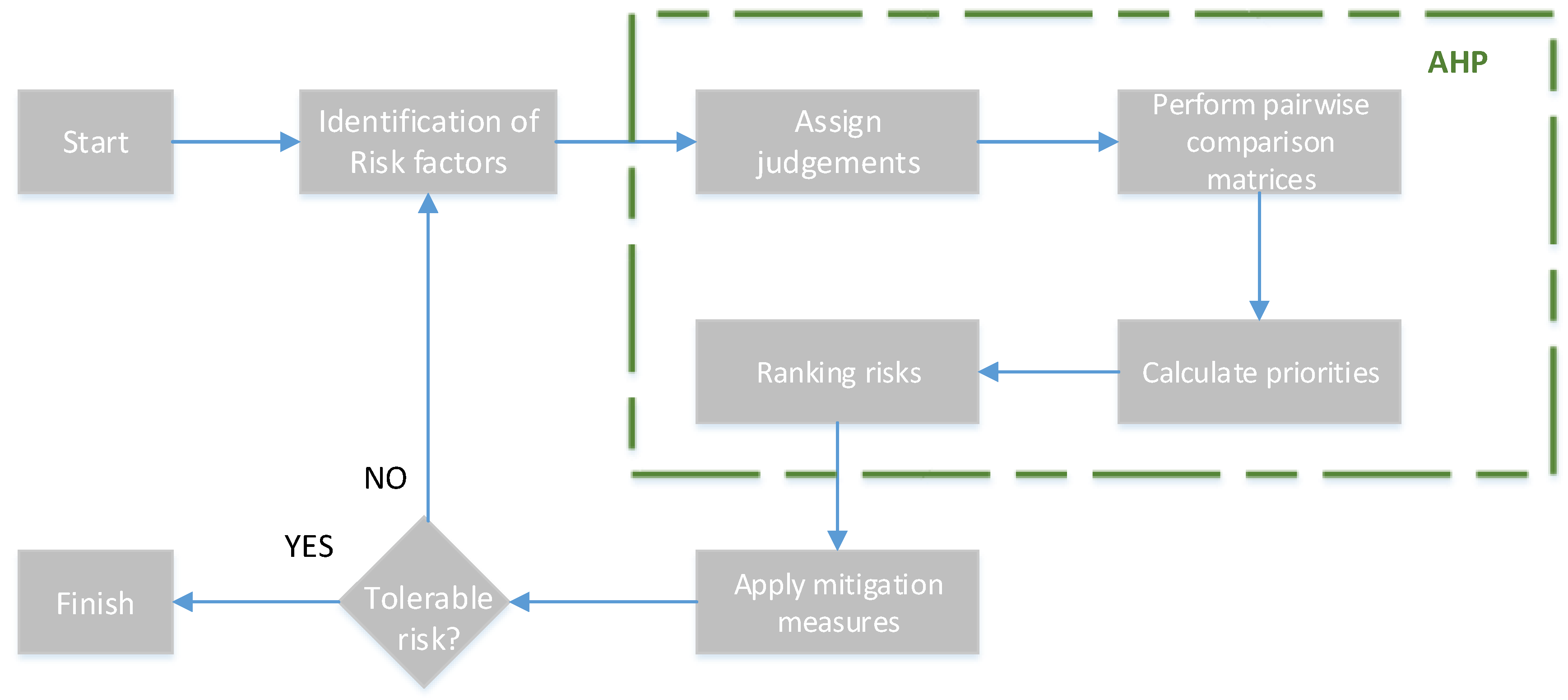
4. The Proposed Framework

Due to the nature of construction sites as one of the most common locations for occurrences of accidents, conducting an evaluation of the project’s safety risk is an essential component of effective construction project management. Figure 2 below depicts the suggested risk analysis and assessment framework based on the AHP application.
Firstly, the risks that might arise during the completion of each task are enumerated, and then the pairwise comparison matrices for those activities are filled up. The standard AHP procedure is used to obtain the weights for each risk, and the ranking is determined by ordering the risks’ weights from highest to lowest. The risk manager is able to allot funding for risk-mitigation measures that may be tailored to the most significant risks associated with each individual activity after the most significant risk associated with each task has been recognized.

5. Application on a Natural Gas Compressor Station Construction Project

The suggested framework was used in a construction project in Greece of the Kipi compressor station of the Trans Adriatic Pipeline, with all the buildings that are foreseen in the relative area. Initially, an administration building that accommodates offices of engineering and management staff that support the station function is built, and it consists of a guard house, offices of engineering and management staff, conference and break rooms, kitchen, sanitary rooms for men, women, and people with disabilities, HVAC, server, electrical room etc. Next, a stores and workshop building accommodates electrical and mechanical workshops, small parts storage, male and female lockers, showers, sanitary rooms, meeting room and break room with kitchen, electrical and server room, archive, workshop office, mechanical workshop, storage area. Also, a utility building provides space for station vehicles as well as space for heating system, instrument and plant air, firefighting material and equipment storage, and lube oil storage. Finally, an electrical and control building, which is the main building that provides space for electricity supply facilities and the operation and control of compressor station, such as transformers (connection to public medium voltage grid), switch gears (medium voltage, low voltage), uninterruptable power supply with battery room, cathodic protection facilities, station control system, and HVAC rooms. The following Table 3 summarizes the tasks of the project and the corresponding risks of each task.
The decision-maker, responsible for making the decisions needed by the multicriteria approaches, was the engineer serving as the risk manager of the project. This technique gives the risk managers a choice mechanism for effectively prioritizing hazards and subsequently leads to efficient allocation restricted budget for expenditures in accident prevention.
The present case study consists of a separate hierarchy for every single task, given that the AHP is applied for the risks of each project activity. For example, the hierarchy for the task “Working at height” consists of three risks (Fall of personnel, Fall of objects, Improper use of portable ladder), which will be assessed using the multicriteria method (Figure 3).
The expert risk manager has to apply evaluations and fill pairwise comparison matrices for the risks of every project activity.
Table 3 shows the risks of each task and the expert’s choices. The influence of each risk on the overall level of safety in the workplace while carrying out each activity is established through the use of pairwise comparisons. The typical AHP technique generates the consistency ratios (CRs) in order to measure and assure that the judgments made by the decision-maker are consistent with one another. The appropriate local priorities that were computed using the typical AHP are outlined in Table 4 below. It is important to point out that every judgment turned out to be accurate, as evidenced by the fact that the CR for each matrix was less than 10%.
Applying the AHP method allows the risk manager to extract more accurate information regarding the importance of each risk for every activity. More specifically, in the last two columns of Table 3, the score of each risk and the corresponding ranking are listed. Thus, the manager identifies the most influential risk factor and can allocate budget resources to reduce as much as possible the total project risk.
In addition, it is worth mentioning that three classes of activities are considered regarding the results. Firstly, there are some activities observed that the first ranked risk is more important than the others. In this analysis, we considered that risk is much more important than the others if it has a score of far more significance than 60% (namely, the sum of scores for the rest of the risks is by far smaller than 40%). In this class belong activities such as T2, T3, T4, T5, T6, T10, T11, T12, T15, T17, T18, T20, and T23. Next, we observed that for some tasks, there is a more critical risk (the one ranked as first), but its score is between 50% and 60%, namely, it is marginally responsible for the majority of the task’s risk. In this group, we classified activities such as T1, T7, T13, T16, T21, and T22.
Finally, we considered a group of tasks for which there is a predominant risk factor, but the majority of the risk of the activity is not due to it. In this class belong activities such as T8, Τ9, Τ14, and Τ19. Figure 4 presents the weight of the first ranked risk for each task of the project.
These findings provide evidence that supports the hypothesis that was initially proposed for this research: that it is essential to make use of a multicriteria analysis method in order to determine the significance of risk factors for project activities. This is because there are activities for which the risk manager needs to revise the given judgments or allot a budget in order to ensure that other risk factors besides the predominant ones are taken into consideration.

6. Conclusions

The technique of assigning priorities to various aspects of risk may unquestionably be of assistance to managers in devising strategies to reduce or eliminate the most significant risk factors via the utilization of preventive measures. A more efficient allocation of a limited budget may reduce costs associated with assistance and mortgages, and in general makes it possible for managers to have the budget available that can be used to reduce project risks to a greater extent. In addition to this, an effective allocation of a limited budget may reduce expenses associated with assistance and mortgages. The key contribution provided by this study is the application of a well-known multicriteria technique to ranking and prioritizing risks. In this case, the AHP was used to express judgments based on the decision-maker’s experience and value system as it related to the analysis of risk factors for each activity in the construction of a natural gas compressor station.
This framework may be used as a guide to help prioritize the implementation of safety measures and the allocation of scarce resources in order to reduce the likelihood of as many accidents as possible. Not only might it be utilized as a teaching tool but it could also be used to help managers with less expertise make better judgments. It might also be used as a template for training newcomers and transferring knowledge from seasoned professionals to others with less expertise. The proposed approach benefits from ability to use the experience, knowledge, and intuition of the person making the decision when determining the weights of the elements. On the other hand, the subjective character of the modeling process is the fundamental flaw of this approach and, more generally, of similar multicriteria methods. This implies that the methodology cannot ensure that the judgments will be absolutely accurate.
Although the proposed method was successful, it might be enhanced by doing a sensitivity analysis on the risk manager’s assessments of the second and third set of risks, i.e., those tasks in which the principal risk is associated with a relatively low overall score. As a result, the proposed framework may be honed to better fit the specific circumstances under investigation.

Author Contributions

Conceptualization, G.K.K., O.E.D., G.G.B. and D.E.K.; data curation, G.K.K., O.E.D. and G.G.B.; formal analysis, G.K.K., O.E.D., G.G.B. and D.E.K.; investigation, G.K.K. and G.G.B.; methodology, G.K.K., O.E.D., G.G.B. and D.E.K.; software, G.K.K., O.E.D., G.G.B.; supervision, G.K.K. and D.E.K.; validation, G.K.K., O.E.D., G.G.B. and D.E.K.; visualization, G.K.K., O.E.D.; writing—original draft, G.K.K., O.E.D. and G.G.B.; Writing—review and editing, G.K.K., O.E.D. and D.E.K. All authors have read and agreed to the published version of the manuscript.

Funding

This research received no external funding.

Data Availability Statement

Some or all data, models, or codes that support the findings of this study are available from the corresponding author upon reasonable request.

Conflicts of Interest

The authors declare no conflict of interest.

References

  1. Neumann, A. The Role of Natural Gas in Europe towards 2050; Edmonds, J., Emberson, D., Gabriel, S.A., Holz, F., Karstad, P.I., Klöckner, C.A., Nord, L.O., Rúa, J., Pollet, B.G., Rasmussen, P., et al., Eds.; NETI Policy Report 01/2021; NTNU: Trondheim, Norway, 2021. [Google Scholar]
  2. Simonoff, J.S.; Restrepo, C.E.; Zimmerman, R. Risk management of cost consequences in natural gas transmission and distribution infrastructures. J. Loss Prev. Process Ind. 2010, 23, 269–279. [Google Scholar] [CrossRef]
  3. Bajcar, T.; Cimerman, F.; Širok, B. Model for quantitative risk assessment on naturally ventilated metering-regulation stations for natural gas. Saf. Sci. 2014, 64, 50–59. [Google Scholar] [CrossRef]
  4. Vianello, C.; Maschio, G. Quantitative risk assessment of the Italian gas distribution network. J. Loss Prev. Process Ind. 2014, 32, 5–17. [Google Scholar] [CrossRef]
  5. Li, W.; Zhang, L.; Liang, W. Job hazard dynamic assessment for non-routine tasks in gas transmission station. J. Loss Prev. Process Ind. 2016, 44, 459–464. [Google Scholar] [CrossRef]
  6. Cinelli, M.; Spada, M.; Kadziński, M.; Miebs, G.; Burgherr, P. Advancing Hazard Assessment of Energy Accidents in the Natural Gas Sector with Rough Set Theory and Decision Rules. Energies 2019, 12, 4178. [Google Scholar] [CrossRef] [Green Version]
  7. Mrozowska, A. Formal Risk Assessment of the risk of major accidents affecting natural environment and human life, occurring as a result of offshore drilling and production operations based on the provisions of Directive 2013/30/EU. Saf. Sci. 2021, 134, 105007. [Google Scholar] [CrossRef]
  8. Mojtahedi, S.M.H.; Mousavi, S.M.; Makui, A. Project risk identification and assessment simultaneously using multi-attribute group decision making technique. Saf. Sci. 2010, 48, 499–507. [Google Scholar] [CrossRef]
  9. Tavana, M.; Behzadian, M.; Pirdashti, M.; Pirdashti, H. A PROMETHEE-GDSS for oil and gas pipeline planning in the Caspian Sea basin. Energy Econ. 2013, 36, 716–728. [Google Scholar] [CrossRef]
  10. Papadopoulou, M.P.; Antoniou, C. Environmental impact assessment methodological framework for liquefied natural gas terminal and transport network planning. Energy Policy 2014, 68, 306–319. [Google Scholar] [CrossRef]
  11. Strantzali, E.; Aravossis, K.; Livanos, G.A.; Nikoloudis, C. A decision support approach for evaluating liquefied natural gas supply options: Implementation on Greek case study. J. Clean. Prod. 2019, 222, 414–423. [Google Scholar] [CrossRef]
  12. Shafiee, M.; Animah, I.; Alkali, B.; Baglee, D. Decision support methods and applications in the upstream oil and gas sector. J. Pet. Sci. Eng. 2018, 173, 1173–1186. [Google Scholar] [CrossRef] [Green Version]
  13. Marhavilas, P.K.; Filippidis, M.; Koulinas, G.K.; Koulouriotis, D.E. The integration of HAZOP study with risk-matrix and the analytical-hierarchy process for identifying critical control-points and prioritizing risks in industry—A case study. J. Loss Prev. Process Ind. 2019, 62, 103981. [Google Scholar] [CrossRef]
  14. Marhavilas, P.K.; Filippidis, M.; Koulinas, G.K.; Koulouriotis, D.E. An expanded HAZOP-study with fuzzy-AHP (XPA-HAZOP technique): Application in a sour crude-oil processing plant. Saf. Sci. 2020, 124, 104590. [Google Scholar] [CrossRef]
  15. Marhavilas, P.K.; Filippidis, M.; Koulinas, G.K.; Koulouriotis, D.E. A HAZOP with MCDM Based Risk-Assessment Approach: Focusing on the Deviations with Economic/Health/Environmental Impacts in a Process Industry. Sustainability 2020, 12, 993. [Google Scholar] [CrossRef] [Green Version]
  16. Marhavilas, P.; Filippidis, M.; Koulinas, G.; Koulouriotis, D. Safety Considerations by Synergy of HAZOP/DMRA with Safety Color Maps—Applications on: A Crude-Oil Processing Industry/a Gas Transportation System. Processes 2021, 9, 1299. [Google Scholar] [CrossRef]
  17. Ratnayake, R.C.; Markeset, T. Technical integrity management: Measuring HSE awareness using AHP in selecting a maintenance strategy. J. Qual. Maint. Eng. 2010, 16, 44–63. [Google Scholar] [CrossRef] [Green Version]
  18. Zheng, G.; Zhu, N.; Tian, Z.; Chen, Y.; Sun, B. Application of a trapezoidal fuzzy AHP method for work safety evaluation and early warning rating of hot and humid environments. Saf. Sci. 2012, 50, 228–239. [Google Scholar] [CrossRef]
  19. Aminbakhsh, S.; Gunduz, M.; Sonmez, R. Safety risk assessment using analytic hierarchy process (AHP) during planning and budgeting of construction projects. J. Saf. Res. 2013, 46, 99–105. [Google Scholar] [CrossRef]
  20. Caputo, A.C.; Pelagagge, P.M.; Salini, P. AHP-based methodology for selecting safety devices of industrial machinery. Saf. Sci. 2013, 53, 202–218. [Google Scholar] [CrossRef]
  21. Podgórski, D. Measuring operational performance of OSH management system—A demonstration of AHP-based selection of leading key performance indicators. Saf. Sci. 2015, 73, 146–166. [Google Scholar] [CrossRef]
  22. Wang, Q.; Wang, H.; Qi, Z. An application of nonlinear fuzzy analytic hierarchy process in safety evaluation of coal mine. Saf. Sci. 2016, 86, 78–87. [Google Scholar] [CrossRef]
  23. Xie, Q.; Ni, J.-Q.; Su, Z. Fuzzy comprehensive evaluation of multiple environmental factors for swine building assessment and control. J. Hazard. Mater. 2017, 340, 463–471. [Google Scholar] [CrossRef] [PubMed]
  24. Janackovic, G.; Stojiljkovic, E.; Grozdanovic, M. Selection of key indicators for the improvement of occupational safety system in electricity distribution companies. Saf. Sci. 2017, 125, 103654. [Google Scholar] [CrossRef]
  25. Kasap, Y.; Subaşı, E. Risk assessment of occupational groups working in open pit mining: Analytic Hierarchy Process. J. Sustain. Min. 2017, 16, 38–46. [Google Scholar] [CrossRef]
  26. Carpitella, S.; Certa, A.; Izquierdo, J.; La Fata, C.M. A combined multi-criteria approach to support FMECA analyses: A real-world case. Reliab. Eng. Syst. Saf. 2018, 169, 394–402. [Google Scholar] [CrossRef] [Green Version]
  27. Gul, M. Application of Pythagorean fuzzy AHP and VIKOR methods in occupational health and safety risk assessment: The case of a gun and rifle barrel external surface oxidation and colouring unit. Int. J. Occup. Saf. Ergon. 2018, 26, 705–718. [Google Scholar] [CrossRef]
  28. Koulinas, G.; Marhavilas, P.; Demesouka, O.; Vavatsikos, A.; Koulouriotis, D. Risk analysis and assessment in the worksites using the fuzzy-analytical hierarchy process and a quantitative technique—A case study for the Greek construction sector. Saf. Sci. 2018, 112, 96–104. [Google Scholar] [CrossRef]
  29. Marhavilas, P.K.; Tegas, M.G.; Koulinas, G.K.; Koulouriotis, D.E. A Joint Stochastic/Deterministic Process with Multi-Objective Decision Making Risk-Assessment Framework for Sustainable Constructions Engineering Projects—A Case Study. Sustainability 2020, 12, 4280. [Google Scholar] [CrossRef]
  30. Marhavilas, P.K.; Koulouriotis, D.; Gemeni, V. Risk analysis and assessment methodologies in the work sites: On a review, classification and comparative study of the scientific literature of the period 2000–2009. J. Loss Prev. Process Ind. 2011, 24, 477–523. [Google Scholar] [CrossRef]
  31. Marhavilas, P.K.; Koulouriotis, D.E. Risk-Acceptance Criteria in Occupational Health and Safety Risk-Assessment—The State-of-the-Art through a Systematic Literature Review. Safety 2021, 7, 77. [Google Scholar] [CrossRef]
  32. Saaty, T.L. The Analytic Hierarchy Process; McGraw-Hill: London, UK, 1980. [Google Scholar]
  33. Saaty, T.L. How to make a decision: The analytic hierarchy process. Eur. J. Oper. Res. 1990, 48, 9–26. [Google Scholar] [CrossRef]
  34. Bougelis, G. Risk Assessment Using Decision Matrix Risk Assessement technique and Multicriteria Decision Making Methods FEAHP and FTOPSIS—Case Study on a Natural Gas Construction Site. Master’s Thesis, Hellenic Open University, Patra, Greece, 2021. [Google Scholar]
Figure 1. The flowchart of the natural gas compression process.
Sustainability 14 13172 g001
Figure 2. The flowchart of the proposed framework.
Sustainability 14 13172 g002
Figure 3. An example hierarchy for T11/Working at height task.
Sustainability 14 13172 g003
Figure 4. The weights of the first ranked risk for every task.
Sustainability 14 13172 g004
Table 1. Summary of the relative literature.
ReferenceNatural Gas Infrastructure Risk Management
Quantitative MethodQualitative Method
Simonoff et al., 2010 [2] X
Bajcar et al., 2014 [3]X
Vianello and Maschio, 2014 [4]X
Li et al., 2016 [5]X
Cinelli et al., 2019 [6]XX
Mrozowska, 2021 [7]XX
Multicriteria methods for oil and gas industry
Quantitative methodQualitative methodPROMETEE, PROMETEE IIREGIMEGroup decision-making
Mojtahedi et al., 2010 [8]XX X
Tavana et al., 2013 [9]XXX
Papadopoulou and Antoniou, 2014 [10]X X
Strantzali et al., 2019 [11]X X
AHP and FAHP applications for health and safety research field
AHPFAHP
Chandima Ratnayake and Markeset, 2010 [17]X
Zheng et al., 2012 [18] X
Aminbakhsh et al., 2013 [19]X
Caputo et al., 2013 [20]X
Podgórski, 2015 [21]X
Wang et al., 2016 [22] X
Xie et al., 2017 [23]X
Janackovic et al., 2017 [24] X
Kasap and Subasi, 2017 [25] X
Carpitella et al., 2018 [26] X
Gul, 2020 [27] X
Koulinas et al., 2019 [28] X
Marhavilas, Tegas, et al., 2020 [29] X
Table 2. The basic scale of the AHP method [33].
DescriptionLevel of Importance
Two factors are equally important 1
Factor i is moderately more important than factor j3
Factor i is strongly more important than factor j5
Factor i is very strongly more important than factor j7
Factor i is extremely more important than factor j9
Intermediate values2, 4, 6, and 8
Table 3. The project activities and corresponding risks.
Activity IDActivityRisk IDRisk
T1CirculationR1.1Driving incident/accident
R1.2Circulation incident on construction site
R1.3Transport of the material
R1.4Weather condition
R1.5Presence of diesel fuel/carburant/lubricants
T2Office workR2.1Bad ergonomic/physical stress
R2.2Climate exposition
R2.3Passive smoke
R2.4Bad hygiene condition
T3Work in open spaceR3.1Bad condition of the ground and working zone
R3.2Presence of insects/wild animals
R3.3Extreme weather conditions
T4Reaction to the emergenceR4.1Unpreparedness of personnel
R4.2Impracticability of emergency ways and exits
T5CoactivityR5.1Simultaneous operations in the same zone
R5.2Degraded situation in the proximity
T6Work in night timeR6.1Prolonged working time
R6.2Reduced visibility
T7Manual workR7.1Bad ergonomic/physical stress
R7.2Torquing
R7.3Fall/impact of equipment and material on the personnel
R7.4Injury by manual tools
T8Lifting operationsR8.1Failure of crane
R8.2Fall of load
R8.3Failure of the lifting
R8.4Persons, equipment and structure in the proximity
R8.5Lifting with construction machinery
T9Excavation and groundworkR9.1Collapsing of soil
R9.2Use of excavator
R9.3Presence of network/cables underground
R9.4Unexploded ordnance
R9.5Open holes and trenches on worksite
R9.6Unfavorable work zone
T10Confined spaceR10.1Unfavorable work zone
R10.2Presence of toxic substances
R10.3Presence of energized sources
T11Working at heightR11.1Fall of personnel
R11.2Fall of objects
R11.3Improper use of portable ladder
T12Scaffolding and PEMPR12.1Work on MEWP
T13Concrete pouringR13.1Use of heavy machinery for pouring
R13.2Use of rotating machine for mixing concrete
R13.3Noise
T14Welding and cuttingR14.1Presence of naked flames/sparks
R14.2Use of rotating and electrical tools
R14.3Optical radiation
R14.4Noise
T15Torch cuttingR15.1Presence of naked flames/sparks
R15.2Presence of gas cylinders
T16Abrasive blastingR16.1Abrasive projection
R16.2Asphyxia
R16.3Environmental pollution
R16.4Noise
T17Painting activityR17.1Use of paints and chemicals
R17.2Fire ignition
T18Use of chemicalsR18.1Exposition to chemical substances
R18.2Storage of chemicals products
T19Use of site enginesR19.1Equipment with internal combustion (compressors, power generator, etc.)
R19.2Rotating engine parts
R19.3Environmental pollution
R19.4Noise
R19.5Use of pneumatic material (grinders, pneumatic hammers, vibrators, etc.)
R19.6High-pressure cleaning
T20Electrical worksR20.1Electrocution
R20.2Use of electrical tools and cables
T21Ionizing radiationR21.1Mobilization of radioactive source on site
R21.2Ionizing radiation
R21.3Incident affecting the source
T22Pressure testR22.1Equipment under pressure
R22.2Overpressure
R22.3Presence of nitrogen
R22.4Environmental pollution
T23Work on energized equipmentR23.1Failure of insulation procedure
R23.2Asphyxia
Table 4. The risk list, judgments, and results for each activity of the project.
Task IDRisk IDPairwise Comparison MatrixScoreRanking
T1 R1.1R1.2R1.3R1.4R1.5
R1.11.000.170.503.005.00 13.36%3
R1.26.001.003.007.009.00 53.37%1
R1.32.000.331.005.007.00 23.59%2
R1.40.330.140.201.003.00 6.35%4
R1.50.200.110.140.331.00 3.34%5
T2 R2.1R2.2R2.3R2.4
R2.11.009.007.004.00 62.88%1
R2.20.111.000.330.14 4.28%4
R2.30.143.001.000.33 9.40%3
R2.40.257.003.001.00 23.44%2
T3 R3.1R3.2R3.3
R3.11.005.003.00 63.70%1
R3.20.201.000.33 10.47%3
R3.30.333.001.00 25.83%2
T4 R4.1R4.2
R4.11.002.00 66.67%1
R4.20.501.00 33.33%2
T5 R5.1R5.2
R5.11.003.00 75.00%1
R5.20.331.00 25.00%2
T6 R6.1R6.2
R6.11.000.50 33.33%2
R6.22.001.00 66.67%1
T7 R7.1R7.2R7.3R7.4
R7.11.003.000.200.33 12.22%3
R7.20.331.000.140.20 5.70%4
R7.35.007.001.002.00 52.32%1
R7.43.005.000.501.00 29.76%2
T8 R8.1R8.2R8.3R8.4R8.5
R8.11.000.505.003.000.25 16.27%3
R8.22.001.006.004.000.50 26.48%2
R8.30.200.171.000.500.14 4.30%5
R8.40.330.252.001.000.17 6.89%4
R8.54.002.007.006.001.00 46.06%1
T9 R9.1R9.2R9.3R9.4R9.5R9.6
R9.11.000.507.005.003.009.0030.61%2
R9.22.001.007.005.004.008.0040.50%1
R9.30.140.141.000.500.252.004.52%5
R9.40.200.202.001.000.504.008.05%4
R9.50.330.254.002.001.005.0013.36%3
R9.60.110.130.500.250.201.002.97%6
T10 R10.1R10.2R10.3
R10.11.000.200.33 10.47%3
R10.25.001.003.00 63.70%1
R10.33.000.331.00 25.83%2
T11 R11.1R11.2R11.3
R11.11.003.005.00 63.70%1
R11.20.331.003.00 25.83%2
R11.30.200.331.00 10.47%3
T12R12.1 100%1
T13 R13.1R13.2R13.3
R13.11.002.004.00 55.84%1
R13.20.501.003.00 31.96%2
R13.30.250.331.00 12.20%3
T14 R14.1R14.2R14.3R14.4
R14.11.000.503.005.00 33.36%2
R14.22.001.003.004.00 45.05%1
R14.30.330.331.002.00 13.60%3
R14.40.200.250.501.00 7.99%4
T15 R15.1R15.2
R11.11.002.00 66.67%1
R11.20.501.00 33.33%2
T16 R16.1R16.2R16.3R16.4
R16.11.002.005.004.00 50.68%1
R16.20.501.003.002.00 26.41%2
R16.30.200.331.000.50 8.63%4
R16.40.250.502.001.00 14.28%3
T17 R17.1R17.2
R17.11.002.00 66.67%1
R17.20.501.00 33.33%2
T18 R18.1R18.2
R18.11.003.00 75.00%1
R18.20.331.00 25.00%2
T19 R19.1R19.2R19.3R19.4R19.5R19.6
R14.11.000.256.004.000.50215.30%3
R14.24.001.009.007.002.00542.35%1
R14.30.170.111.000.500.140.253.03%6
R14.40.250.142.001.000.200.54.94%5
R19.52.000.507.005.001.00425.73%2
R19.60.500.204.002.000.2518.66%4
T20 R20.1R20.2
R20.11.000.50 33.33%2
R20.22.001.00 66.67%1
T21 R21.1R21.2R21.3
R21.11.000.502.00 28.57%2
R21.22.001.004.00 57.14%1
R21.30.500.251.00 14.29%3
T22 R22.1R22.2R22.3R22.4
R22.11.005.003.006.00 57.67%1
R22.20.201.000.502.00 12.51%3
R22.30.332.001.003.00 22.16%2
R22.40.170.500.331.00 7.66%4
T23 R23.1R23.2
R23.11.002.00 66.67%1
R23.20.501.00 33.33%2
Publisher’s Note: MDPI stays neutral with regard to jurisdictional claims in published maps and institutional affiliations.

