1. Introduction
Over the last forty to fifty years, surfboards have evolved from mainly handcrafted to large-scale global industries. The essence of surfing remains the same, its essential instrument, which physically connects humans and nature. It is not only a piece of equipment but also carries cultural, social and emotional significance [
1].
Following the surf industry’s growth, the surfboard’s design and function have undergone significant changes over the years. They have become shorter and lighter and have transitioned from longboards of up to five meters in length made out of solid wood to boards as short as one to two meters made out of mainly petrol-based polymers, such as expanded polystyrene (EPS), polyurethane foam (PU) and fibreglass. Regarding functionality, the addition of fins to the board’s underside changed the dynamics of surfing by giving surfers more control when manoeuvring. The board shape evolved to have more angled noses with an upward curvature [
2]. These changes have made the boards more hydrodynamic, enabling the creation of more lift and forward thrust as the water is steered along the base to the board’s tail when on a wave. When the board flexes during the manoeuvre, it stores the energy released as an acceleration burst when returning to its standard shape after exiting the turn [
3]. Therefore, the surfboard’s composite material ability to go through this flexing with little fatigue and other factors such as weight, stiffness and the actual shape’s design determines how dynamic a board will be.
However, despite the evolution in design and performance, this transition from a handcrafted to mass-produced item has brought many environmental issues and concerns. Regarding the use of materials, the surfboard industry is heavily dependent on petroleum-based polymers that require high energy consumption, thus emitting more greenhouse gases (GHG) during manufacturing and impairing the boards’ recyclability. Moreover, like many other mass-consumerist commodities, modern surfboards are not meant to last long. They have become disposable items with short life spans, considering that nowadays, a regular recreational surfer can go through up to three PU surfboards yearly [
4]. Some other issues are related to the toxicity of petrochemicals and their impacts on health during the production process. Such types of non-eco-friendly oil-derived materials are not in line with the mindset of the surfer community.
To overcome these problems, some innovative solutions have emerged as ecologically sustainable alternatives. A few examples include a PU foam core blank made with 40% castor oil and a resin with more than 90% linseed oil [
5]; the use of sugar beet oil instead of PU together with hemp cloth replacing some of the fibreglass [
6]; and a study to implement honeycomb-structured 3d printed cores [
7]. Furthermore, initiatives such as the ECOBOARD, introduced by a non-profit benchmarking agency, that aims to create a certification for boards that have been produced in a way that minimises environmental impacts to provide consumers with more transparent information, are helping reduce the effects caused by the industry [
4]. Being an ancient and primordial material in surf history, wood attracts more fans nowadays due to its aesthetic look and reduced environmental impact. Wood is now a feasible option when buying a surfboard, although its weight can ultimately affect performance. An alternative is to add a thinner outer layer of wood to a Styrofoam core; however, production is more time intensive. Only a tiny portion of the surfboard is effectively sustainable.
Cork is the new revolutionary material in the surf industry. It is a 100% natural material possessing unusual properties such as low density and multi-functionality. Being a cellular material, it features an interconnected network of cells to fill the internal space, thereby optimising the load resistance with reduced density. It is referred to as the “green foam”, and not only is this material an excellent shock absorber, but its softness also causes it to act as if it was an internal mattress for the surfer’s heels [
8]. Cork is also a damper, helping to reduce structural vibration and the slamming effect, an excellent surfboard property. The authors of [
9] concluded that even the slightest use of cork (two curvilinear cork stringers embedded in an EPS core) can reduce the torsional stiffness and provide more damping than a traditional PU board with wooden skin. Finally, this remarkable material is also water-resistant and reflects the new ideology of Eco design and Eco efficiency in products.
Today, the most common way to manufacture a surfboard using cork is with cork skins. Some shapers also associate wood with it. Cork skin surfboards have a foam block as the core material for the structure, and the surface is covered with a thin layer of white cork agglomerate. Using this technology, the surfboard remains lightweight due to the low-density foam core and is more sustainable. By using a layer of white cork agglomerate, the surfboard does not need to be glassed. As cork will not rot in the presence of water, glass fibre can be avoided, thus reducing the environmental impact. Moreover, the cork’s surface is a natural, non-abrasive and non-slippery surface [
10].
To fill the research gap regarding surfboards made from sustainable materials, this work presents an innovative solution towards creating more sustainable surfboards by using expanded cork as the core material. Such an application reduces carbon emissions as well as increases recyclability and inclusion in a circular economy. This proposal of using expanded cork as a core material aims to fill the current gap in the surf industry concerning more sustainable alternatives by replacing fossil-based materials that are harmful to the very environment that the surfing culture values. Moreover, addressing some of the seventeen goals established by the United Nation’s 2030 Agenda for sustainable development, [
11] introduces a higher added-value application for a material mainly applied as an insulator.
2. Background
Expanded cork (EC) agglomerate, more known as black cork, is made from the expansion of virgin cork granulates that agglutinate between them. The virgin granulates come from the outer bark of oak tree branches due to their low commercial value and use. These tree branches have a higher resin (suberin) concentration than other kinds of cork, for example, from the stem [
12]. After the pruning process, the bark is extracted from the branches and submitted to a grinding process to achieve a final granular size of 3 to 10 mm for acoustic insulation and 5 to 22 mm for thermal insulation purposes. The raw material used for EC manufacturing has high levels of impurity (e.g., wood fragments), which need to be excluded from the process. Such a procedure is conducted using densiometric separators, rotating drums or pneumatic sorting systems [
13]. The granules are placed into autoclaves for the expansion and aggregation process, and pressure is applied to the granules by the hydraulic bottom (or top). This compression is used to control the final dimensions and density of the product, generally in the range of 110–150 kg/m
3 (depending on the desired final density). The granules are bonded together by overheated steam at 300–370 °C and 40 kPa in a closed chamber [
12]. They undergo a process of expansion due to the volume increase in the cork cells, resulting in the release of suberin, which is responsible for the granules’ agglutination. This resin is what supports the agglomeration without the use of any synthetic binding agent [
14]. The steam-baking process varies from 17 to 30 min, depending on the initial moisture levels [
15]. The industrial process energy used to produce such a product comes essentially from biomass fuel. The burning of cork dust, a carbon-neutral energy source, corresponds to over 93% of the total necessary energy [
16].
When the bark is extracted, the tree produces new bark, promoting more CO
2 fixation directly [
17]. The 2.3 million ha of cork oak forests worldwide are seen as promoting the retention of about 14.4 million tons CO
2/year. It should also be noted that for each kg of cork extracted, 0.379 kg of CO
2 is emitted. However, it retains approximately 4.8 times that value (1.833 kg of CO
2) [
12].
The expanded cork board (ECB) has a negative value of equivalent CO
2 emissions of −116.229 kg CO
2/m
3, considering the embodied CO
2 in cork at the end of the production cycle. Compared to other insulation materials such as polyurethane (PU), Extruded polystyrene (XPS), Expanded polystyrene (EPS), lightweight clay aggregates (LECA) and stone wool (SW), EC is the only one with a negative carbon footprint [
18]. In addition, the insulation of ECB has been reported to maintain essential properties for more than 40 years [
17], meaning black cork can be re-used in several applications (building thermal insulation, etc.) during its lifetime. If it is not possible to keep using it in the same way due to contamination or damage, it could be ground for incineration or other potential applications.
EC is becoming a common choice for multiple applications. Its retail price is still expensive compared to other materials in the construction industry for insulation (3 to 4 times higher than conventional materials such as XPS and EPS, respectively). Nevertheless, its thermal conductivity is superior to these cheaper and non-sustainable options. EC is also being used in home furniture and wall interior covering for aesthetic reasons.
Cork is being also employed in sandwich structures. Cork sandwich structures have been used in the aircraft industry, where the mechanical properties of cork are considered essential to develop strong and lightweight components. The study of cork properties concluded that using cork agglomerates as a core material could bring many exciting features to the sandwich compound. Generally, sandwich structures with cork as the core material have higher flexural strength than conventional options. It is also an essential fact that cork decreases the possibility of crack propagation. Some studies compare the use of agglomerated cork in sandwich materials with insulation foam [
19]. The samples with agglomerated cork or foam as the core material and were further laminated with glass fibre on the top and bottom. After the tests, the results showed that the high-density cork core displayed better strength parameters than the lower-density foam core. During the tests, it was observed that the cork core materials returned to their original shape after being loaded. In contrast, the foam core material presented plastic deformation.
When exposed to a fatigue test, the sandwich samples had different responses, and as expected, foam core materials failed earlier. The cork core was shown to be the most resistant, presenting no catastrophic failure after 8000 cycles (see specification on [
20]). Composites of low-density foam (Divinycell H60) were destroyed when exposed to 860 sinusoidal loading cycles. As mentioned before, the destruction mechanism in the samples was completely different. On the one hand, foam materials were destroyed by violent cracking. In contrast, cork core materials presented cracking in the glass-epoxy, but the core material returned to its original shape after the test.
A study analysing and combining multiple natural materials was conducted by [
21]. Composites based on natural materials using cork’s intrinsic characteristic of excellent recovery capacity and flax fibres as an outer layer of protection led to a material with good strength and a positive impact on the environment. However, the negative aspect of this new composite is the weight and price. The combination of two natural materials with bio-resins leads to an authentic, sustainable product. The use of wood is also a solution for an increase in the material’s strength.
3. Materials and Methods
3.1. Materials
The challenge of developing a sustainable surfboard starts by selecting the raw materials that will be used. The desire to reduce the environmental impact of surfboards leads to decisions being passed in the search for more sustainable or bio-based materials. In terms of resins and fibre cloths, there are already many plant-based feasible options, but in terms of blocks, the possibilities are limited. White cork agglomerate has been used in surfboards but is limited due to its higher density (≈165 kg/m
3 or more). Expanded cork, however, with a lower density (≈110 kg/m
3), also has good energy-absorption capabilities and a negative carbon footprint [
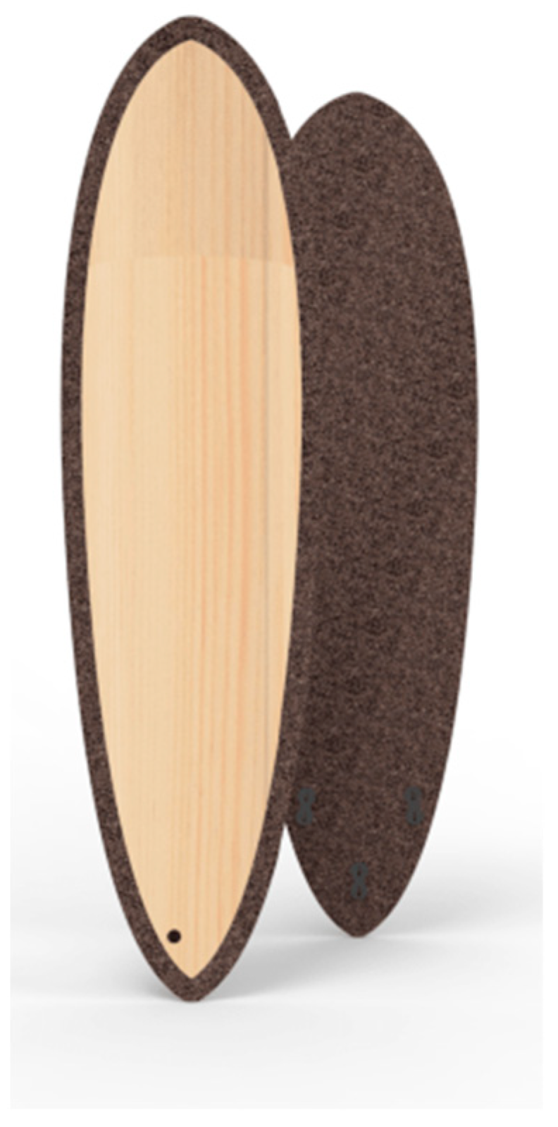
22]. This last feature is a significant source of motivation and makes this material stand out from the remaining conventional options. In addition, it was intended that this surfboard could be manufactured following the traditional surfboard’s manufacturing processes. To be appropriately used as a core material, the expanded cork will need extra support once the granules’ aggregation with suberin cannot withstand high bending and torsion loads during surf practice. For the surfboard here proposed, to grant it structural resistance, a top wooden layer is added as skin, giving mechanical resistance to bending and wear and creating an entirely natural composite (
Figure 1). The thickness of the wooden layer was set to be around 3 to 4 mm, which aligned with the fibreglass to increase the whole structure’s resistance. Since all of the athlete’s weight is located on the feet, which could potentially cause local damage to the board, the presence of wood becomes essential to dissipate concentrated loads and energy transferred from the surfer’s heel to the surfboard.
When it comes to aesthetics, it was essential to use fibreglass combined with a thin resin film in order to create a transparent and stiff layer so that the core material, the cork, would become visible to the customer. Moreover, the selection of noble materials was not only due to their addition of value to the overall product’s aesthetics, but also because all their mechanical properties matched the needs of this project.
As the board’s weight is always a concern, its volume was reduced to a minimum. The increase in a surfboard’s volume makes surfing easier [
23], but on the other hand, if its dimensions increase, so will the corresponding weight. The dimensions of the designed surfboard are 6′6″ in length, 21.50″ in width and 2.62″ in thickness (192 × 54.61 × 6.65 cm). The total volume of the surfboard is 41.9 litres (0.0419 m
3), and the corresponding weight is 6.84 kg, composed of the components described in
Table 1. Normal shortboards are 6′0” in length (180 cm) and 30 litres in volume (0.03 m
3), which creates a buoyancy force of 15.45 N (considering that it is 50% underwater). If the weight of the surfboard is increased in addition to the low volume, the necessary lift force will be greater. For the proposed surfboard design, the same boundary conditions are considered (50% volume underwater). The corresponding buoyancy force is approximately 21.6 N. By adding 20 cm in length and ≈12 litres in volume (0.012 m
3), the weight increases by 1.95 kg. Still, the buoyancy force is now 6.15 N. Low buoyancy is a common problem of small size surfboards, and that is why only expert surfers can manage to surf easily on them. Considering that the expanded cork surfboard will have extra weight, it is necessary to increase volume.
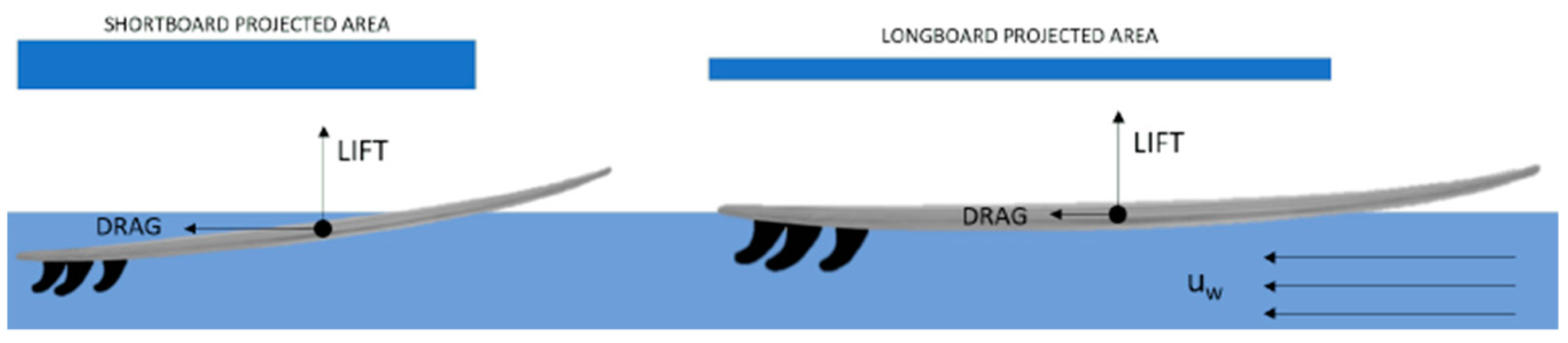
Figure 2 shows the different forces acting on a surfboard in uniform water flow. The drag is higher on small surfboards because of the projected area perpendicular to the flow of water.
3.2. Mechanical Testing
In order to evaluate the performance of the developed laminated composites for surfboards, uniaxial tensile and compression tests were performed on the skin and core materials, respectively, and 3-point bending tests to the entire composite structure. Then, the complete surfboard structure was virtually tested through finite element analysis after previous validation of the mechanical tests.
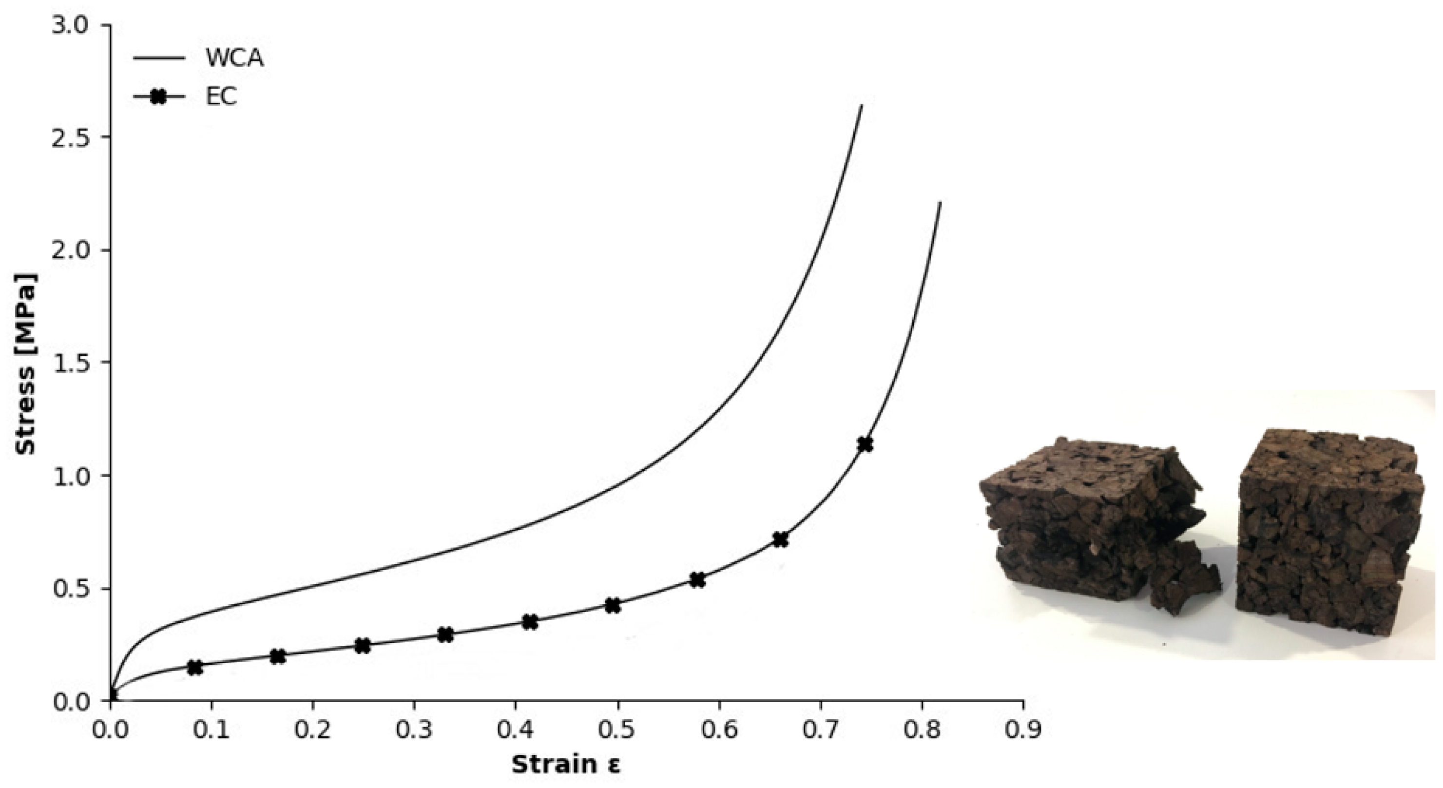
3.2.1. Uniaxial Compression Tests of Core Material
The uniaxial quasi-static compression tests were performed in a SHIMADZU AGS-X 10 kN machine [
24] at a low loading rate (10 mm/min). The 60 × 60 × 60 mm samples (mass density ≈ 92 kg/m
3) were placed in the machine compression plates and then tested until the densification point was reached.
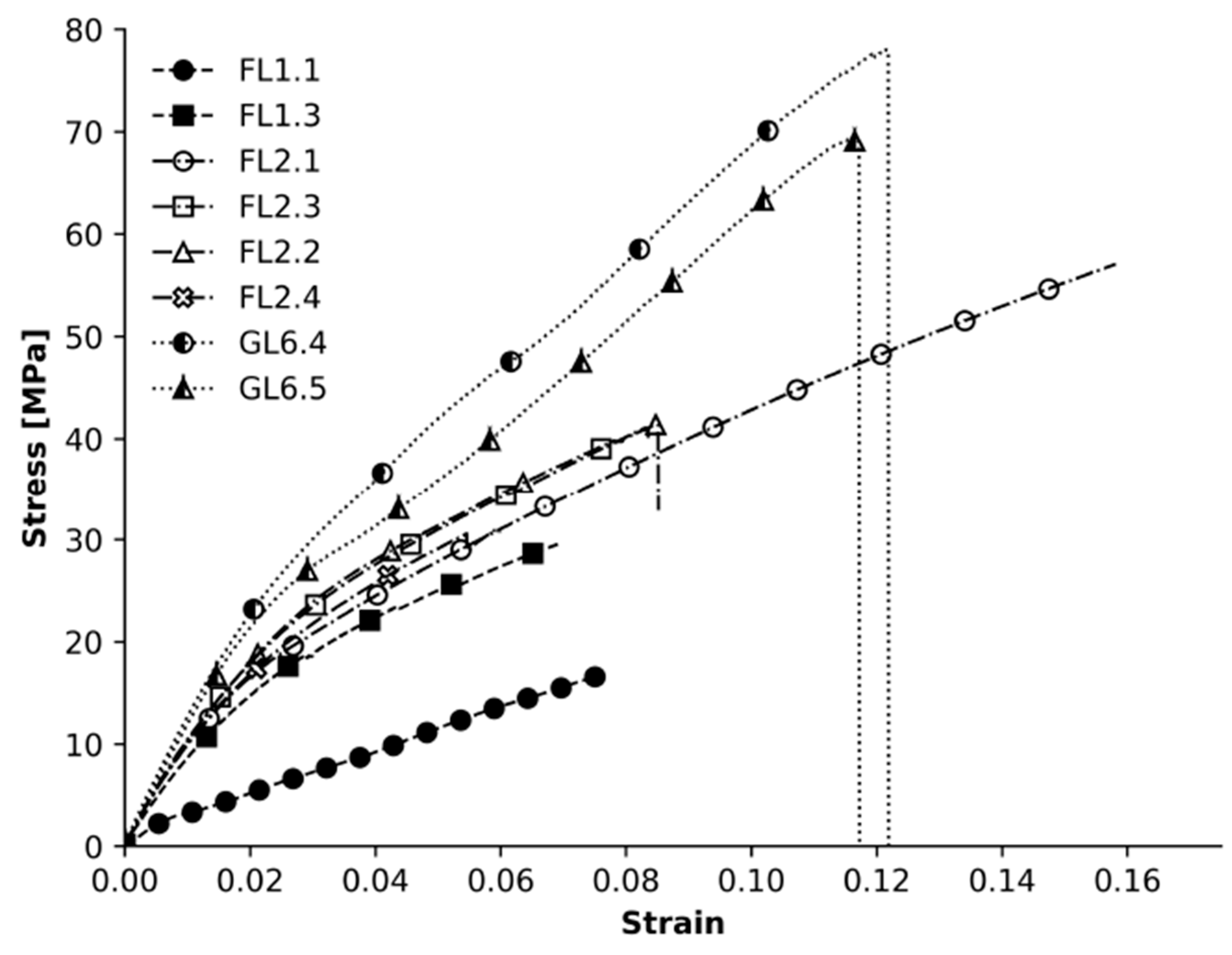
3.2.2. Uniaxial Tensile Test of Skin’s Fibres
To determine Young’s modulus and the ultimate tensile strength (UTS) of the external skin layers, four different types of samples were manufactured following ASTM D3039, which suggests that for polymer matrix composites, the samples should be rectangular with a gauge length (Lg) between 125 and 150 mm and a tab length (Lt) of 38 mm. The tests were performed in a Shimadzu AGx Plus 10 at a 10 mm/min strain rate. The composition of each of the samples is summarised in
Table 2.
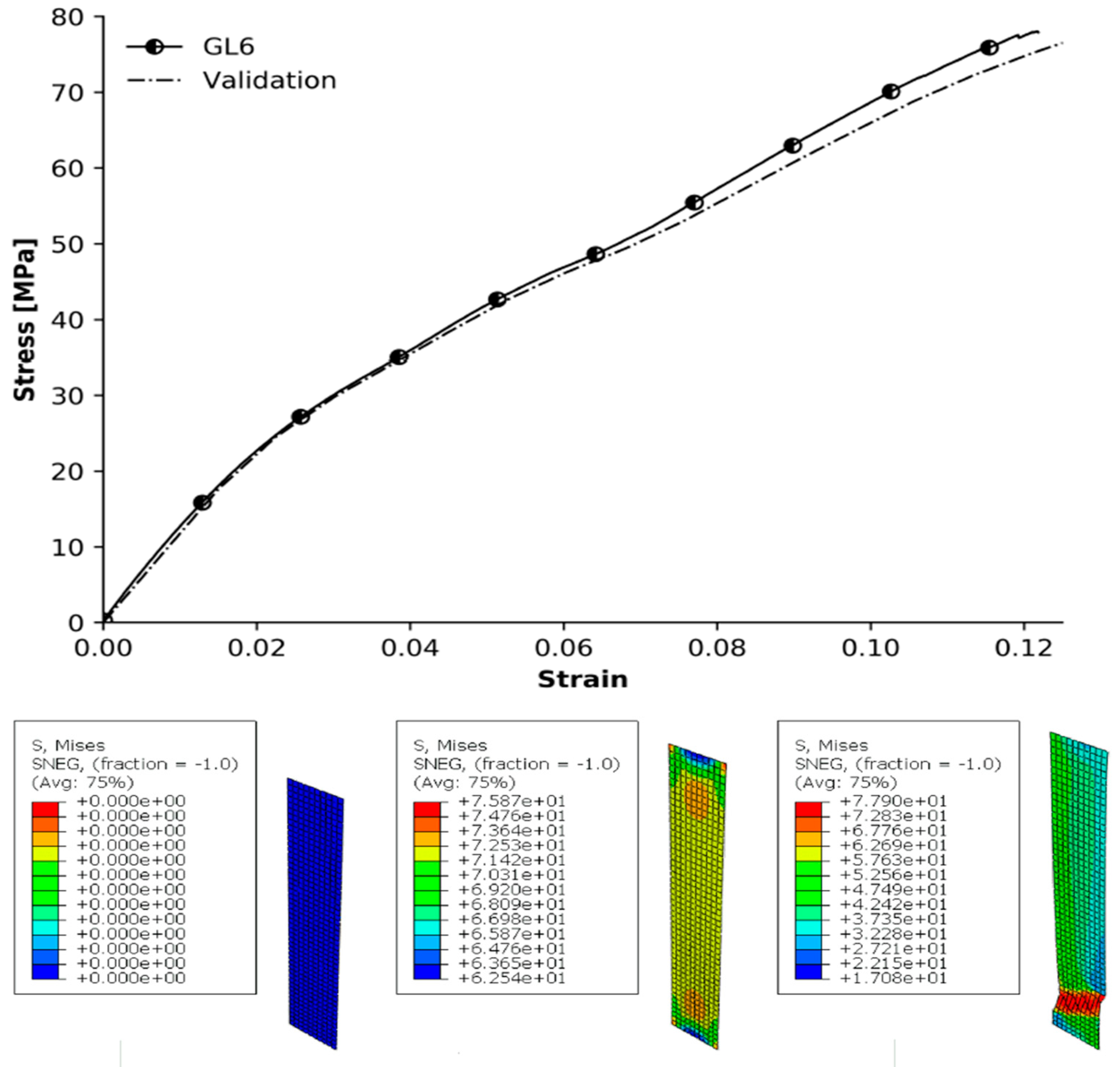
Glass fibre (GL) is a widespread solution for surfboards. GL6 samples try to replicate them through two layers of 6 oz glass fibre cloth with polyester resin acting as the matrix. This is the conventional method used in surfboards shells and will be used as a reference point for comparison. Flax fibre (FL) is a common natural material used in the textile industry and has the potential to be used in many different applications, including surfboards. Ref. [
25] proposed and produced a surfboard with flax fibres as the outer layer. However, the core remained a polyurethane foam. The fibre’s natural origin and properties make it a potential suitable replacement for synthetic ones in terms of performance and sustainability. The fibre alignments are bidirectional, the same as glass fibre cloth. Therefore, they have all the characteristics to perform similarly. The produced samples are made from 1 and 2 layers of flax fibre reinforced with a PE resin acting as the matrix.
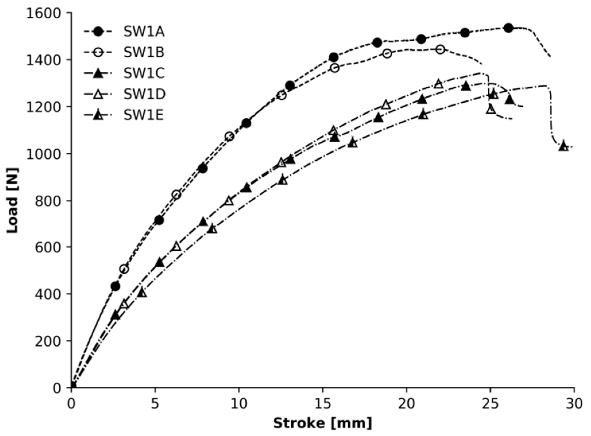
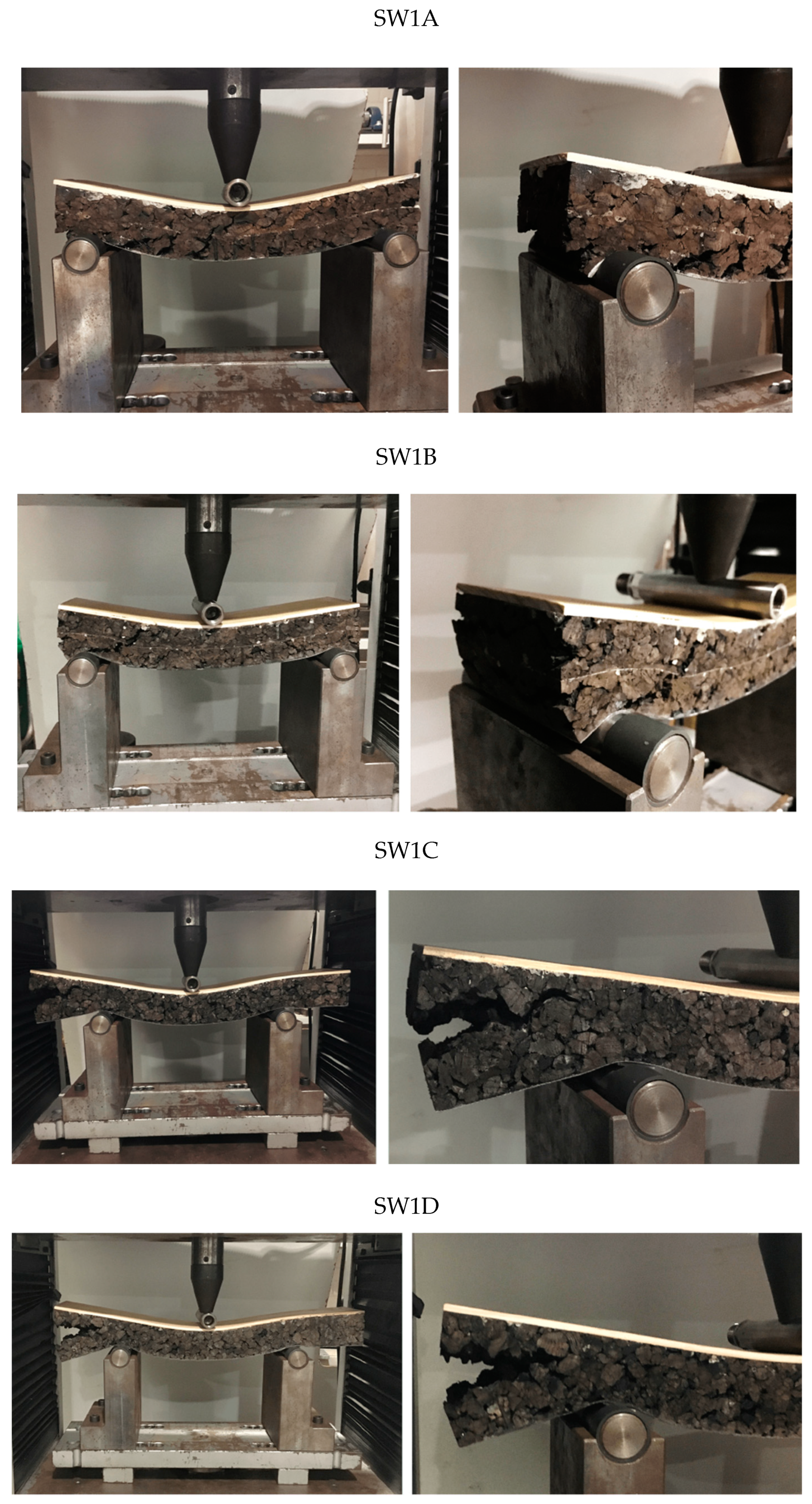
3.2.3. Bending Tests of Composite Laminates
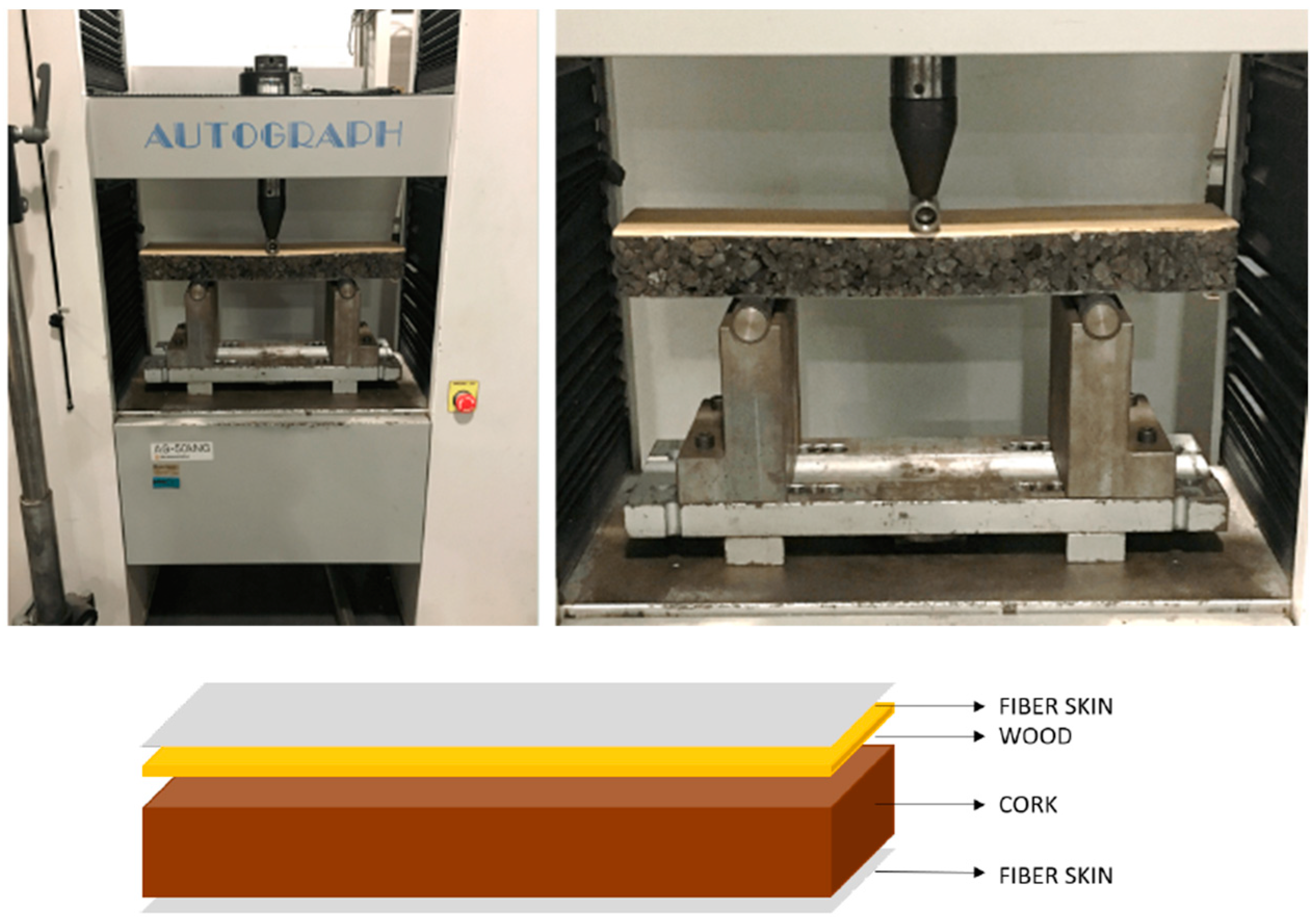
Three-point bending experiments are helpful to determine the flexural modulus of the composite’s structure. The tests (
Figure 3) were carried out according to the ASTM C393 standard. A Shimadzu universal testing machine, equipped with a 50 kN load cell, was used, and the velocity was set to 10 mm/min. The supports and the loading tool have a diameter of 28 mm and 25 mm, respectively. Five samples were tested, SW1A and B with a heterogeneous core and SW1C, D and E with a homogeneous core. All the samples were visually analysed, checking the type and regions of failure. Although the ASTM C393 standard determines the mechanical properties, such as shear stress in the core and stress at the compression faces, this work solely focuses on studying the samples’ bending stress behaviour. More specifically, the relation between load and displacement, when the sample fails and the cause.
To produce the intended sandwich-like composite, it was first necessary to cut 300 × 100 × 40 [mm] strips from an EC block and 300 × 100 × 3 [mm] from a wood panel. The latter was then glued on top of the EC using polyurethane glue. The fibre cloth was applied directly to the structure through dry “in situ” using polyester resin as the layer’s binding agent. Samples were denoted as SW1A to SW1E.
3.3. Virtual Tests
Finite Element Analysis (FEA) was employed to develop the surfboard’s numerical model, to assess if the chosen design and materials could withstand all the loads and stress that originated during surf practice. Most of the studies with an engineering approach to surfboards focus on the fins [
26,
27,
28,
29] and make use of numerical simulation of the hydrodynamics—through computational fluid dynamics (CFD) software—to assess how their design, quantities and position affect the board’s overall performance. To the best of the author’s knowledge, no studies use FEA to simulate stresses and deformations on the surfboard’s structure as a whole, only targeting the fins [
30].
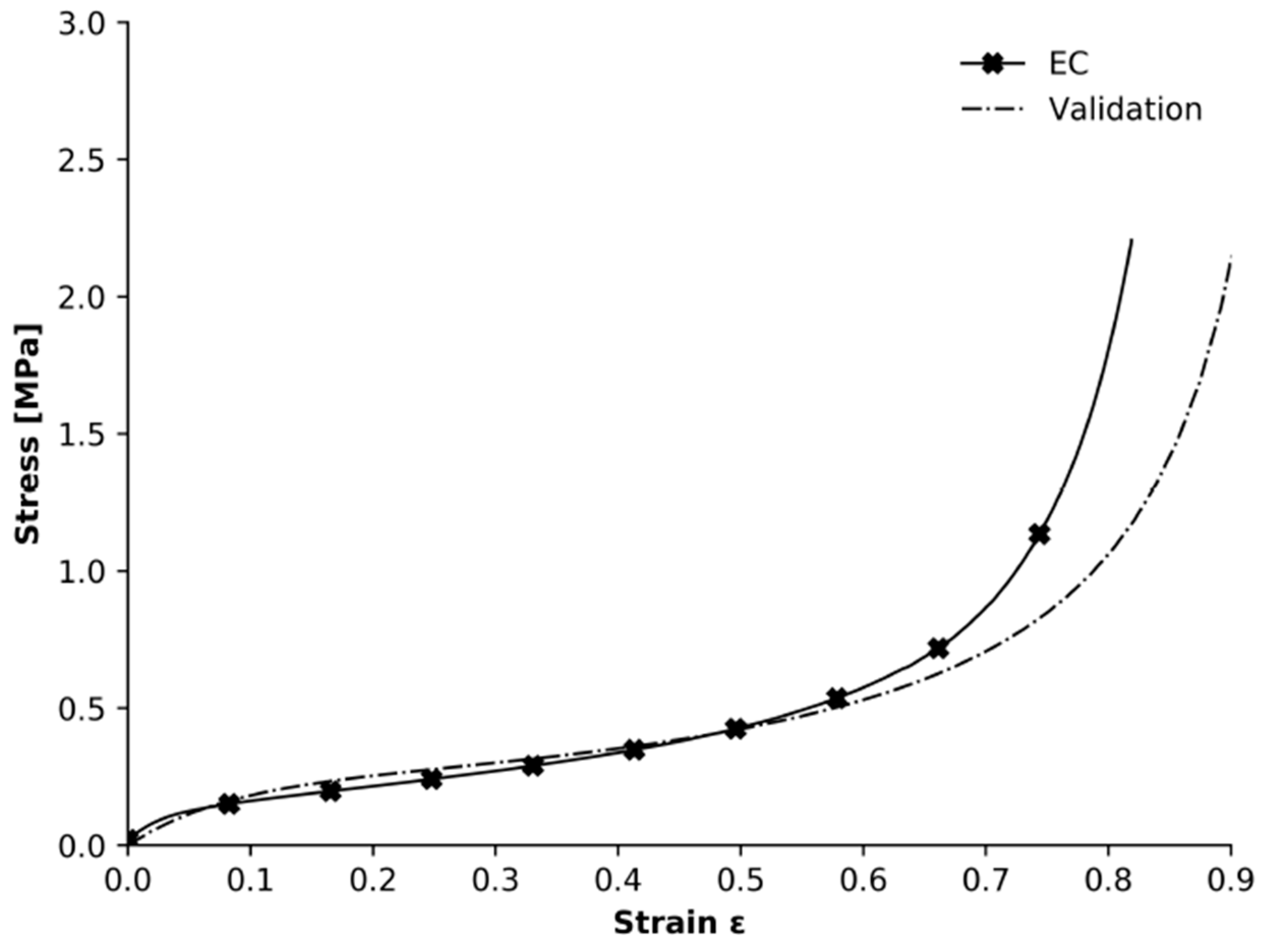
Before working on the entire model, one must validate the mechanical behaviour of the employed materials. To do that, the previous mechanical tests were replicated virtually. Uniaxial compression was simulated for EC, tensile tests for fibreglass and a 3-point bending test for the sandwich composite. The software used for the numerical simulation was Abaqus in its standard mode (implicit), and loads were considered quasi-static.
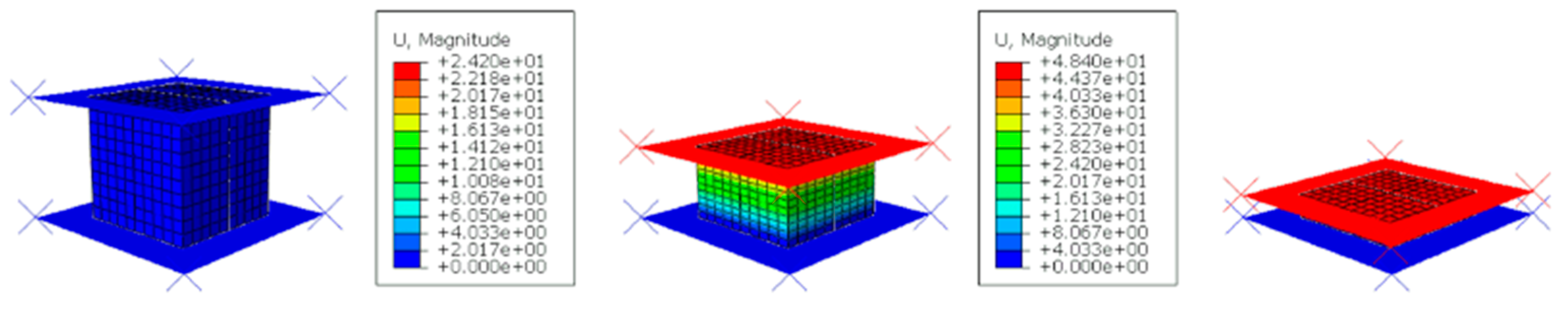
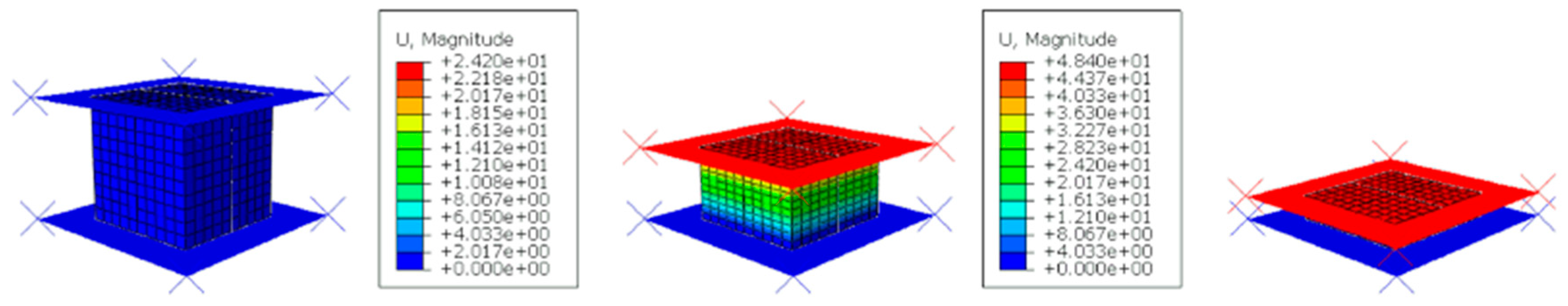
3.3.1. Uniaxial Compression of Core Material
To numerically validate the compression test, an apparatus that allowed us to simulate the compression of a cork block (60 × 60 × 60 mm) in between two rigid plates was designed on Abaqus. The plates were modelled as rigid shells, which makes them non-deformable. Therefore, the stresses and deformations only affect the cork block—a deformable 3D solid modelled using linear, fully integrated hexahedrons (C3D8). The upper plate displaces 55 mm towards the cork fixed on the bottom plate (fixed in all degrees of freedom) and compresses it, as seen in
Figure 4.
Cork properties were defined based on experimental data using the crushable foam material model. This is the most accurate method to virtually replicate the behaviour of expanded cork.
3.3.2. Uniaxial Tensile Test of Skin’s Fibres
After validating the core material, the model of the external layers was validated. These parts sized 200 × 20 mm were designed on Abaqus as a 3D deformable shell, given that their length is much bigger than their thickness. The boundary conditions of the experimental setup were easily replicated. The material’s elastoplastic experimental behaviour was inserted via tabular data, and first-order 4-node shells (S4) were used (500 elements). Quasi-static implicit analysis was once again chosen.
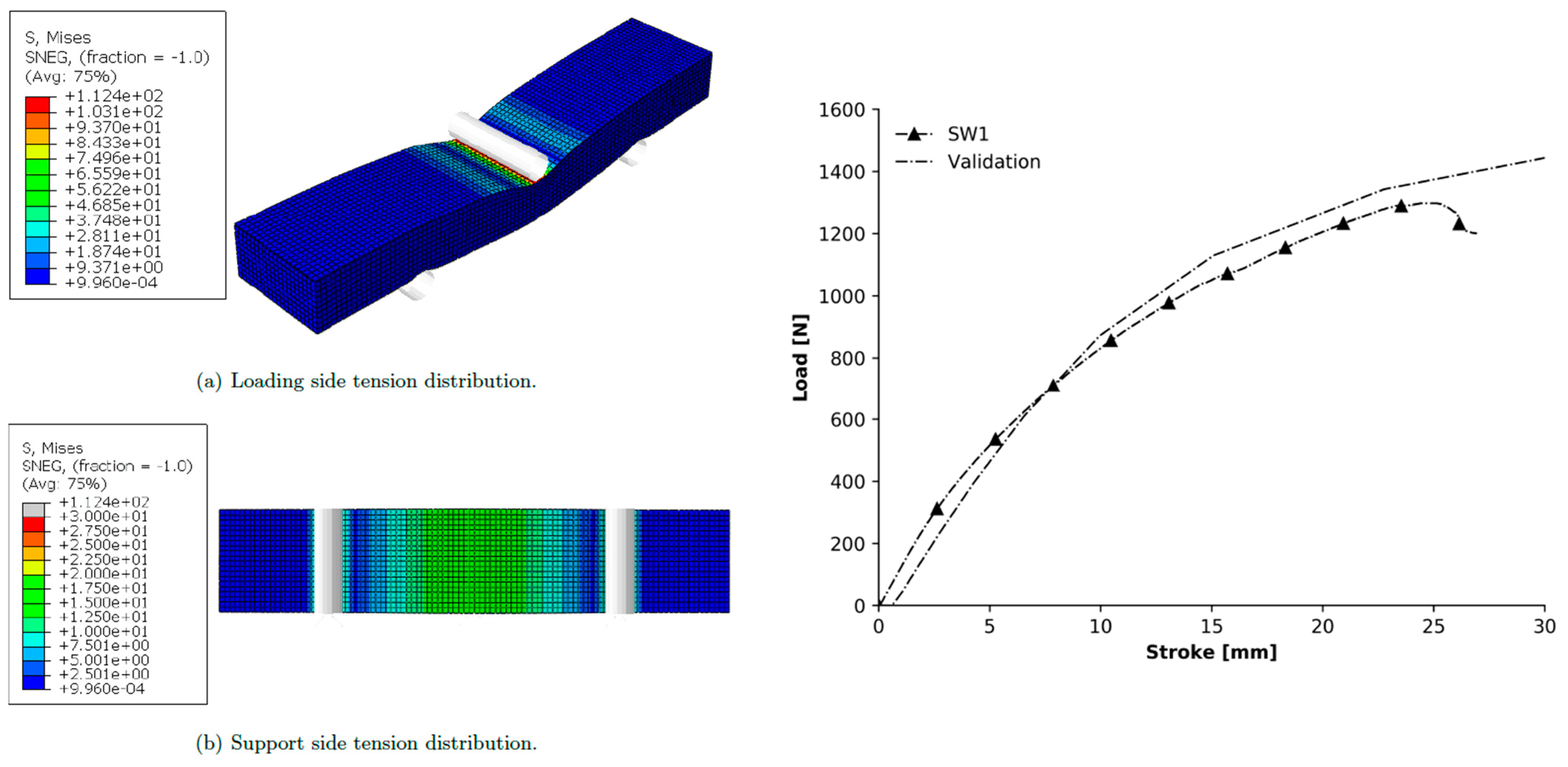
3.3.3. Bending of Composite Laminates
For the 3-point bending validation, it was necessary to assemble the three constituent parts of the physical model, i.e., the two external layers and the core. To model the top layer, subjected to compression, only wood was considered since it is 7.5 times thicker than the fibreglass, withholding all the compressive loads imposed. Wood behaviour was deemed to be of a linear elastic nature. The bottom layer was modelled using the elastoplastic model discussed above for the fibres. The final assembly structure was composed of the bottom shell layer, fibreglass with a section thickness of 1 mm (GL6), the 50-mm-thick EC core and the 3-mm-thick top layer of pine wood, also modelled as a shell.
The material properties of the fibreglass layer and EC were the ones validated before. As for the pinewood, 3 GPa was considered for its Young’s modulus and isotropic behaviour to simplify the model as much as possible. The wood was designed as a 3D deformable shell with a section of 3 mm and meshed with 2000 S4 elements. The remaining parts of the sandwich composite, namely the core and the fibreglass layer, have, respectively, 20,000 C3D8 and 2000 S4 elements. The model constraints totalled just two. Tie constraints between the core and both the top and bottom layers were used to reproduce their genuine connection. To properly replicate the experimental test, three rolling cylinders with the exact same dimensions as the real ones were created and added to the assembly to represent the supports.
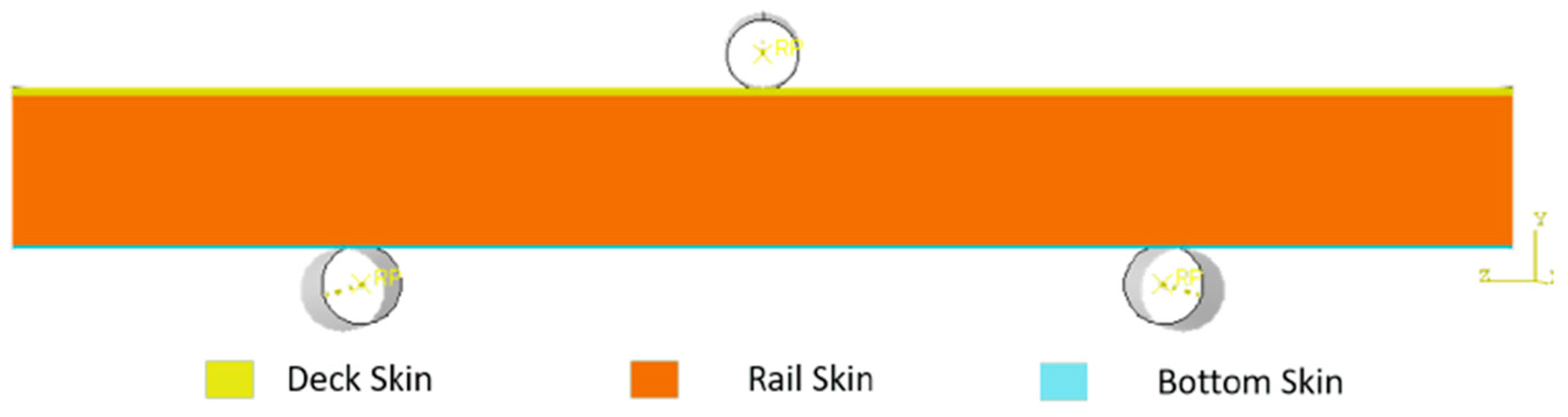
Regarding their boundary conditions, they were set to be free on their rotational axis degree of freedom. The contacts between the simulation parts were general surface-to-surface contacts with a defined friction interaction of 0.2. Finally, before running the simulation, a displacement of 30 mm was applied to the top roller towards the sandwich sample. The schematic of the simulation is presented in
Figure 5.
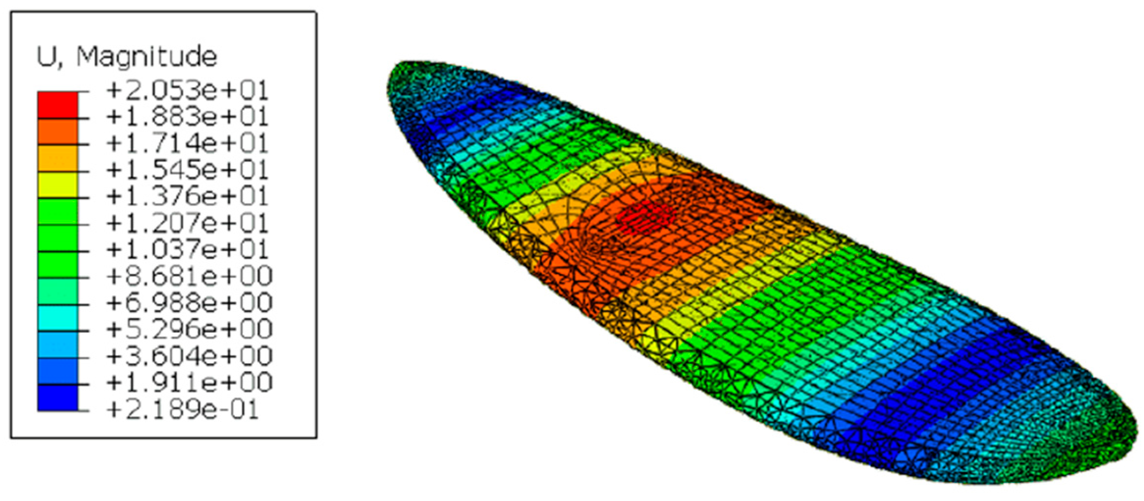
3.3.4. Bending of the Surfboard Structure
Finally, to characterize the fully completed surfboard’s structural model on Abaqus, it was necessary to import the CAD (IGES files) of the different parts, previously designed in Solidworks. The structural model is formed by three main components: The cork core, wooden top layer and fibreglass skin that covers the whole board. In
Figure 6, it is possible to differentiate the cork core in white and the top wood layer in dark red. Using Abaqus’ skin function, adding the extra fibreglass layer (in green) was then possible.
Material data were imported from the previous validations for each part of the surfboard. The interactions between the different materials were defined with tie constraints; the wood layer is” bonded” to the cork core, and the outer skins are necessarily attached to the parts they are offsetting. The parts were meshed independently with different types of meshes: The wood layer was discretised with 848 S4 elements, which are the most appropriate elements to simulate thin surfaces; the cork’s mesh is made of 8620 C3D10, i.e., 10-node second-order quadratic tetrahedron elements (free from locking issues). To impose boundary conditions and loads, one must remember that ocean conditions are highly unpredictable and hard to test outside of the natural environment. Multiple situations could be generated because the surfboard is basically a beam and the surfer is a mass point loaded on top of it. Nowadays, surfboard manufacturers do not follow a particular standard for surfboard resistance because most surfboards are not mass-produced. For some companies, though, a methodology can be defined. Torflex’s work [
31] served as an inspiration to install some testing procedures to characterize the bending, torsional and vibrational frequencies of surfboards. The setup adapted to the Abaqus environment is depicted in
Figure 7. After fixing the supports, the displacement of the loading tool was set to 50 mm.
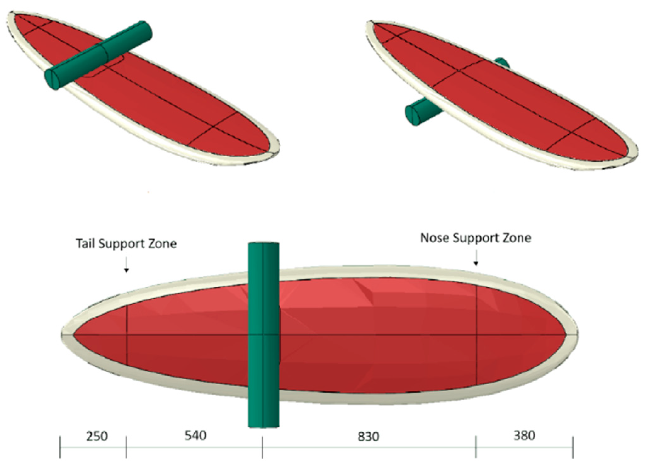
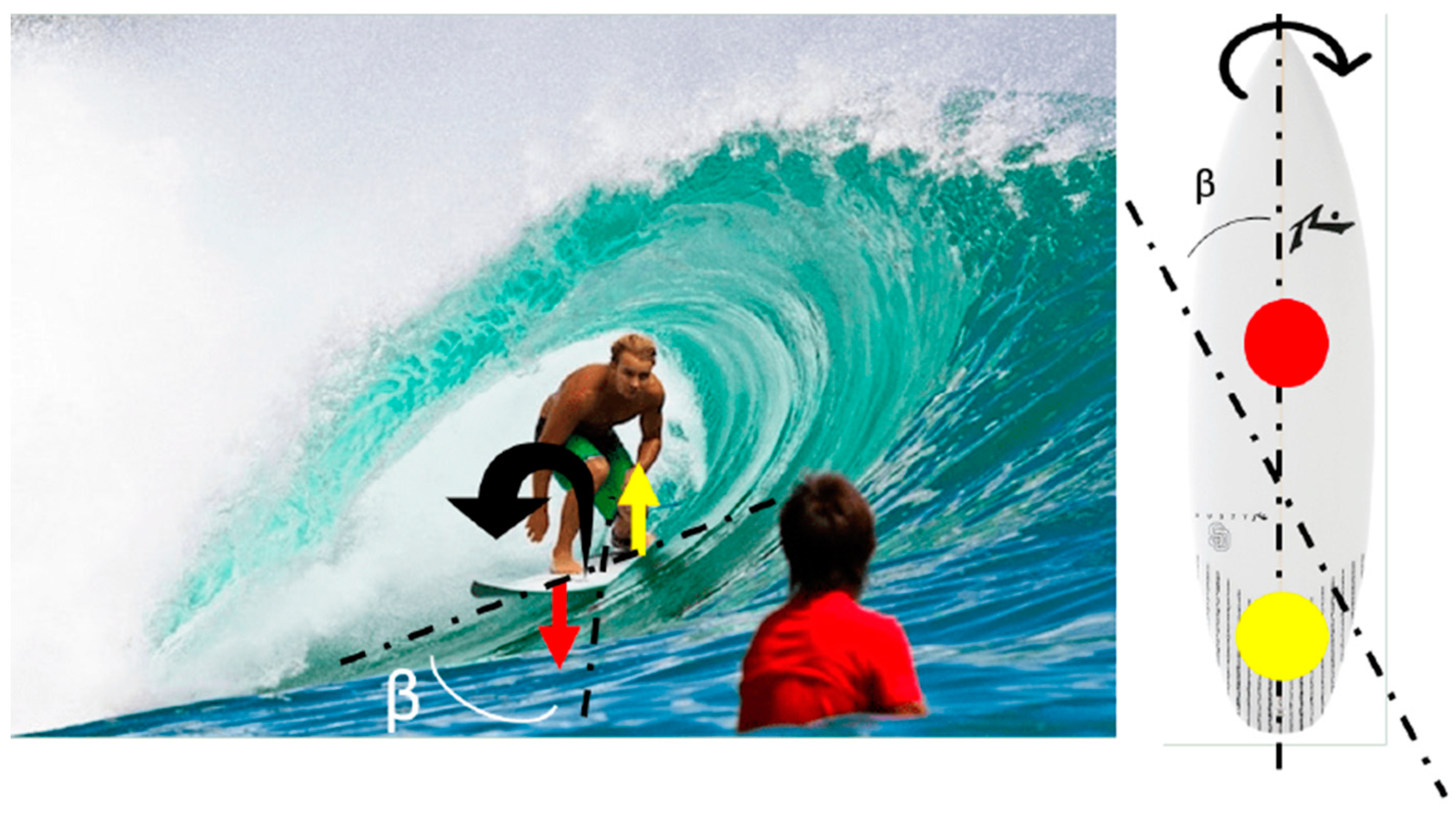
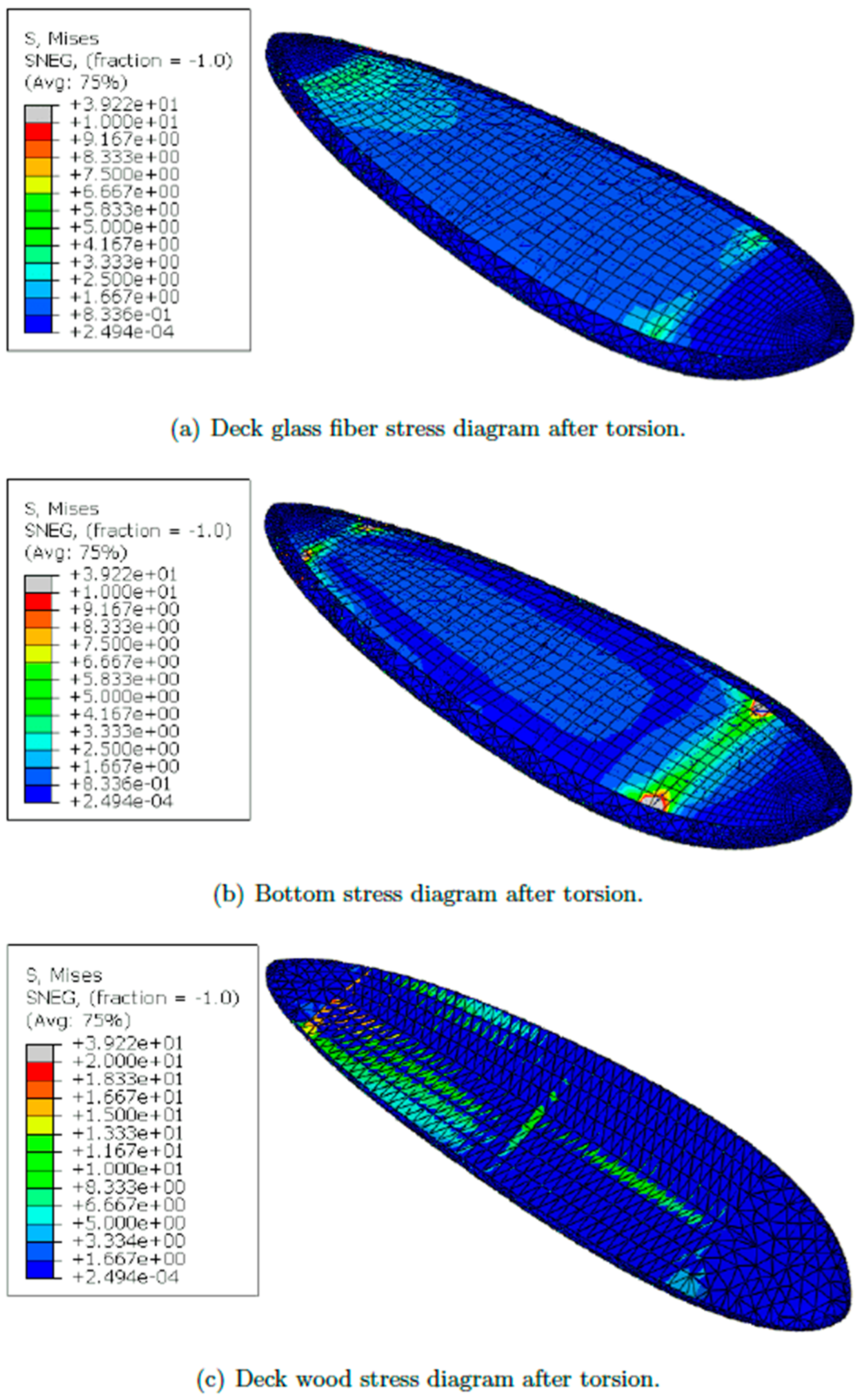
3.3.5. Torsion Loading of the Surfboard Structure
Torsional shear stresses are also crucial for surf practice, especially during curves and fast direction changes. For the torsion test, the tail side of the surfboard was fixed, blocking all the DOF. Then the front support was rotated. A rotational value of 15 degrees was defined to simulate the torsion of the surfboard. In this situation, only part of the surfboard (tail) is in contact with the water, and the remaining (nose) is unsupported, as seen in
Figure 8. The force created by the weight on the front foot of the surfer is represented as red in the figure, whereas the reaction force of the water on the tail of the surfboard is in yellow. Considering that these two forces are acting in opposite directions and that the surfboard is at an angle (β) with the wave, momentum is created, and consequently, the surfboard will tend to twist. There are no reference values of torsion. Thus, 15 degrees was considered for the studies, although this value should be smaller in real scenarios.
3.4. Environmental Impact Study
After designing the product’s virtual prototype, it is essential to evaluate the resulting impacts of the production. For the life cycle assessment (LCA) evaluation, the web-based software Ecolizer was used [
32]. It was also necessary to analyse material extraction to the manufacturing processes and their energy consumption. This software uses Ecoinvent’s database [
33] and Simapro’s calculation power [
34]. There are some database limitations in terms of materials, such as resins and the desired types of foams for this study. To overcome this difficulty, various studies collected information about the different materials’ contribution to global warming. From [
18], the corresponding contributions of CO
2 equivalent for foams were derived, which are essential for future analysis. The comparison between glass and flax fibre is made in [
35], where they concluded that the natural fibre has a much better environmental impact than glass fibres. Relative to resins, the authors of [
36] performed a study where the global warming contribution of epoxy was considered to be lower than polyester resin.
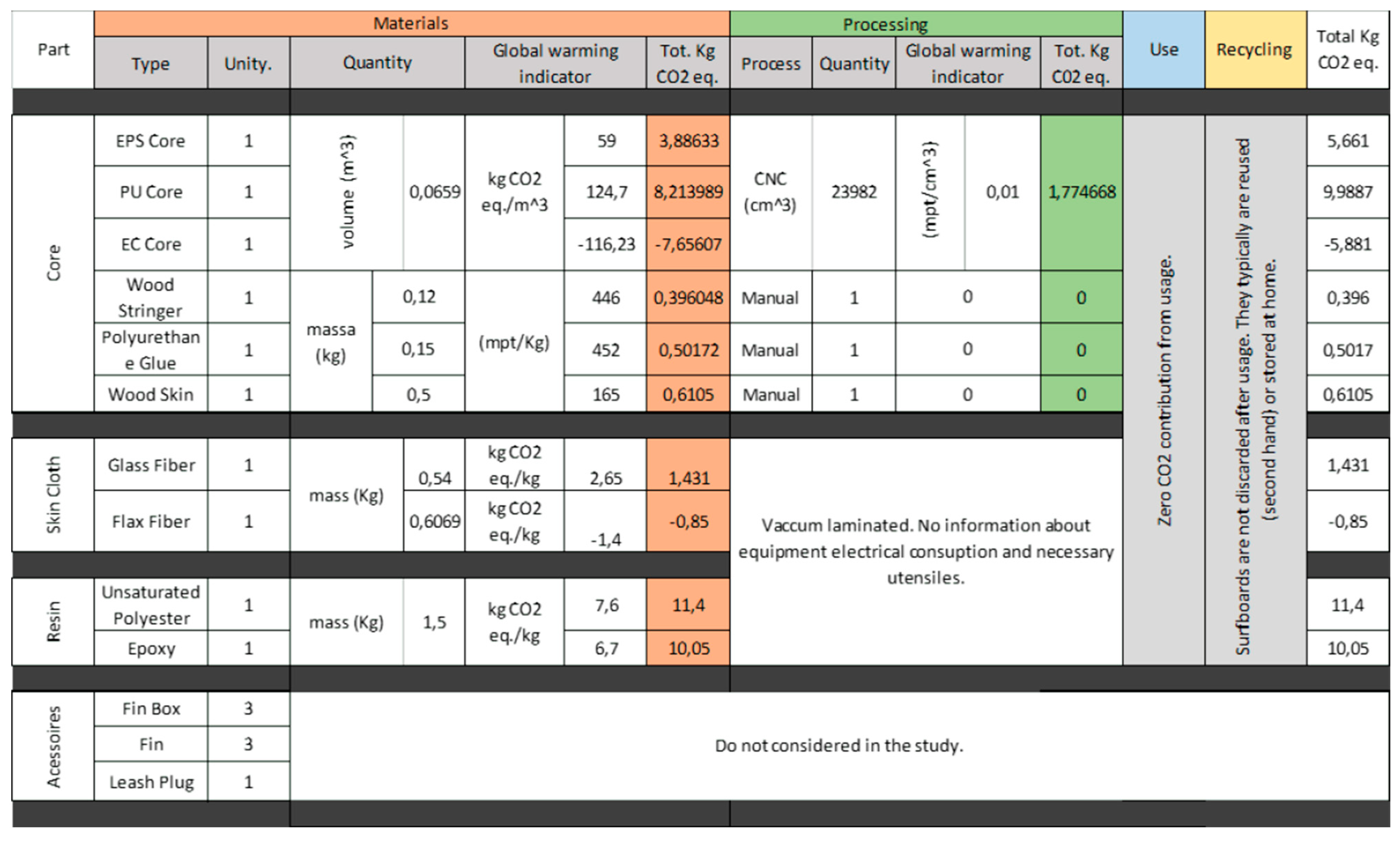
The study only considered the direct influence of the material in the final product’s impact. The transportation of raw materials and delivery from factory to retailer or client are not accounted for. The study’s goal is to evaluate the different possible combinations of materials and the comparative CO2 equivalent emissions. Regarding the surfboard’s manufacturing processes, the majority is performed by hand and has no direct contribution. A deeper analysis would consider the amount of energy used to run the facilities (electricity, cleaning and maintenance of tools and equipment).
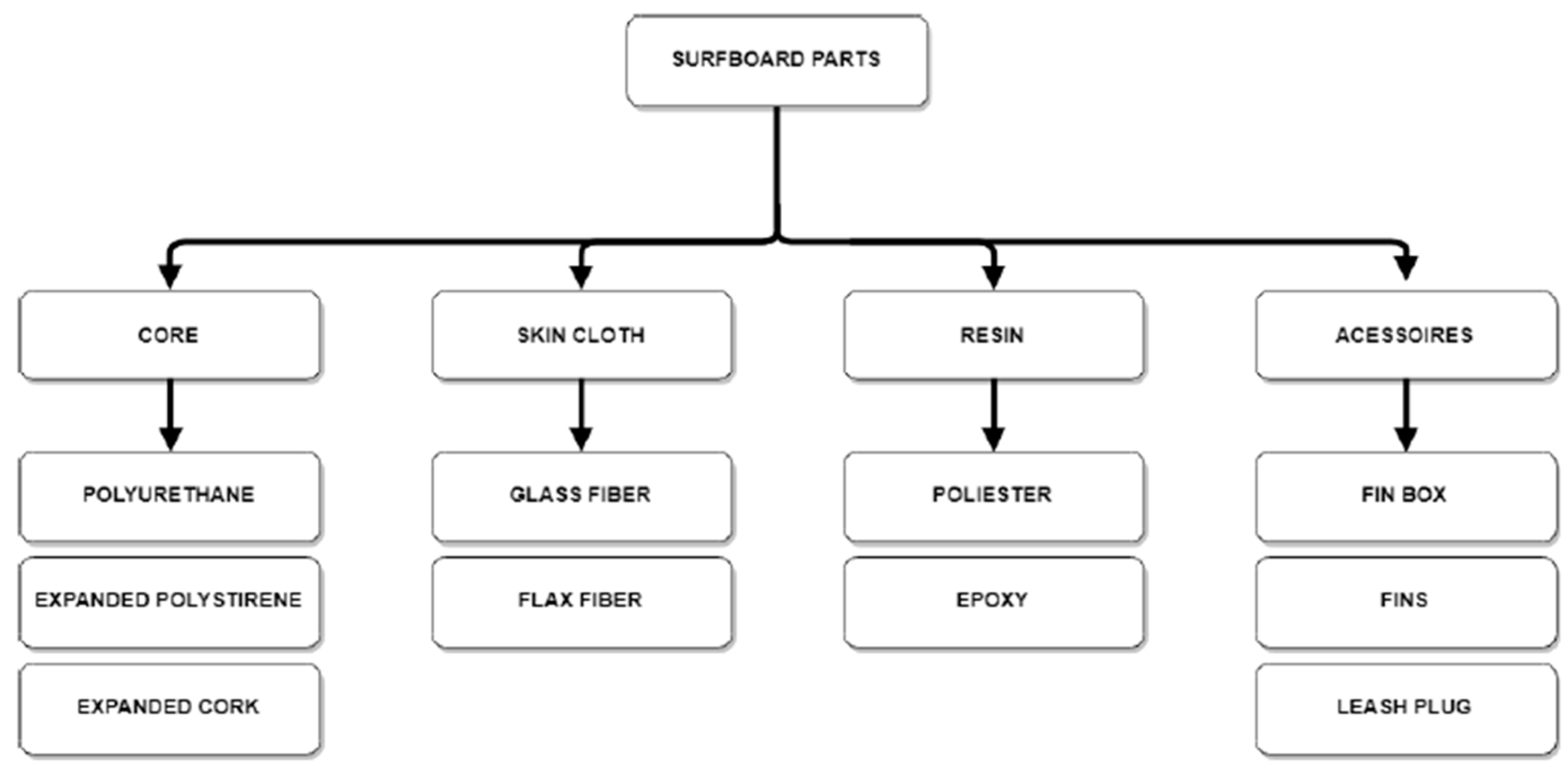
Moreover, this industry produces a lot of waste, such as the residual dust that originates from the process. Therefore, all the disposable protection gear needed—gloves, sticks and duct tape—should be considered more accurate. Surfboards are made of four essential parts: Core, skin cloth, resin and accessory parts.
Figure 9 shows the different possibilities to produce conventional surfboards in each category. The present assessment only considers the three first columns. The environmental indicator of this analysis is based on the CO
2 equivalent, which has a consequential impact on global warming. Natural materials during their lifetime retain CO
2; consequently, if the processing steps do not add carbon to the final process, their contribution to sustainable products is essential. For core materials, the best option is expanded cork with retention of CO
2 due to the eco-friendly manufacturing process. Nowadays, the most used core is still PU, although surfers are gaining some awareness and choosing EPS, which offers the same properties with reduced environmental impact. Even so, EPS is not eco-friendly when compared to cork.
Besides PU foam, resin is the raw material with the higher indicator per unit considered. For the resin, a practical assessment of the contribution of the manufacturing process of multi-part resins formulations was considered. The authors of [
35] performed a multi-stage methodology that is more relevant to the batch processes used in manufacturing many structural systems. Again, the amount of material used is the same, and the consequent contribution is differentiated by the eco-indicator. The study produced up to 6.7 and 7.6 kg CO
2 when 1.5 kg of epoxy and unsaturated polyester resin were used, respectively.
5. Discussion and Conclusions
The overarching objective of this study was to find an alternative solution to the traditional PU-based surfboards and combine environmental and structural advantages. Wooden surfboards may be less reliant on petrol-based materials; however, they have less manoeuvrability and more performance issues when compared to a composite fibre one [
4]. Moreover, other more sustainable alternatives proved to have much lower mechanical properties when compared to the current surfboard’s standard materials—Bio-Foam presented a much lower compressive core shear strength when compared to PU and hemp cloth laminates are far less effective than fibreglass to protect cores [
41].
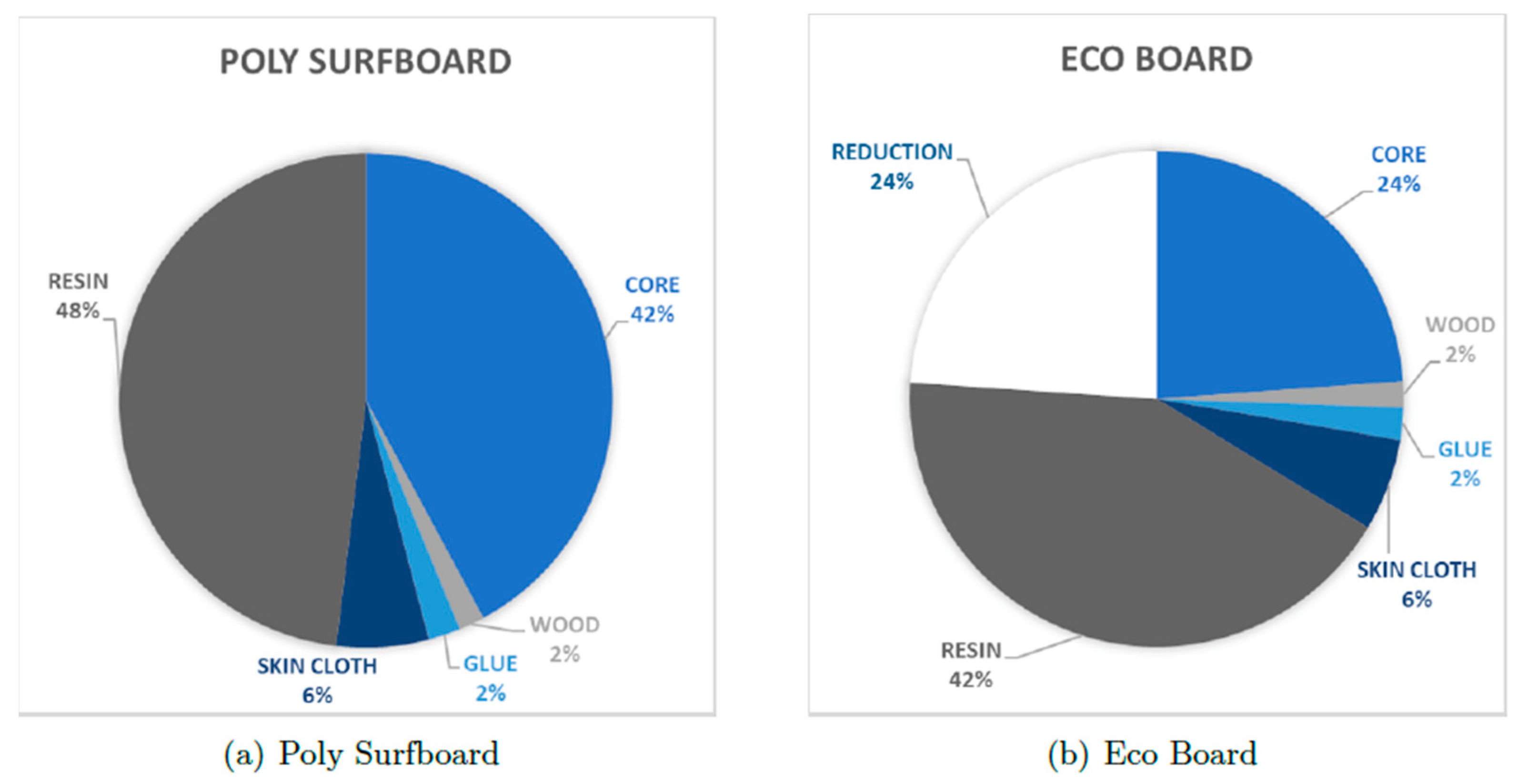
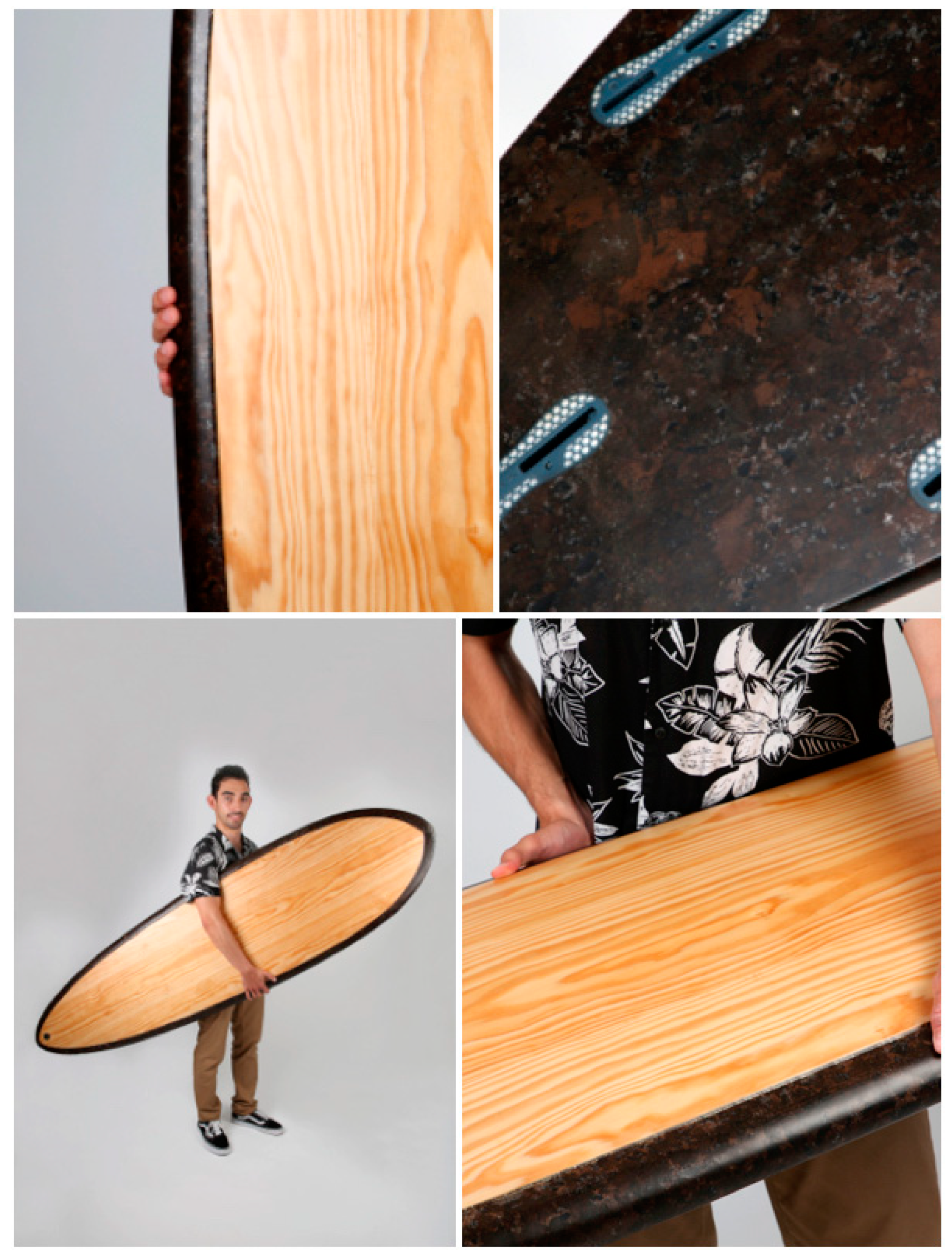
This present study introduces an environmentally sustainable alternative (
Figure 24) that does not compromise the board’s performance. The mechanical and numerical testing demonstrated that the combination of expanded cork, wood and fibreglass results in a very resistant composite that is able to withstand a great amount of force without failing. The investigation method has shown that numerical tools can effectively be used to speed up product development times and provide reliable structural analysis results once materials and boundary conditions are carefully set. Besides a good mechanical performance, this combination also does well in terms of the environmental impact by reducing carbon emissions by almost 63%. Not only does it reduce the carbon footprint but also the toxicity in manufacturing processes, since PU blanks contain ingredients that are harmful to the long-term health of whoever is handling the material.
Nonetheless, this study also has some limitations. The composite developed herein is not yet fully optimised for the production of surfboards, so there is still room for improvements. The bending tests were only performed on the developed composite and not in a PU core, so there may not be a direct comparison between the proposed solution and the standard one. Due to the manufacturing process, this material is still too heavy compared to the current material on offer and has a weak connection between particles, needing extra structural strength. Because of this, further studies and development must be performed in the structural design of the surfboard to reduce the weight and increase the strength. Furthermore, the use of bio-based resin may have a massive impact on the product’s life cycle assessment with similar mechanical performance.
Besides these limitations, this material has great potential as a blank material for surfing and other sports such as kayaking given its outstanding sustainability and excellent mechanical properties. Sustainability is an essential concern that society must have embedded in its core, and studies like this one are a small step towards winning the battle against climate change whilst raising awareness for the importance of reducing carbon emissions.


 ,
, 


